EP3613877B1 - Verfahren und vorrichtung zum elektrolytischen polieren - Google Patents
Verfahren und vorrichtung zum elektrolytischen polieren Download PDFInfo
- Publication number
- EP3613877B1 EP3613877B1 EP19747162.6A EP19747162A EP3613877B1 EP 3613877 B1 EP3613877 B1 EP 3613877B1 EP 19747162 A EP19747162 A EP 19747162A EP 3613877 B1 EP3613877 B1 EP 3613877B1
- Authority
- EP
- European Patent Office
- Prior art keywords
- hollow pipe
- electrolyte
- electrolytic polishing
- pipe
- liquid buffer
- Prior art date
- Legal status (The legal status is an assumption and is not a legal conclusion. Google has not performed a legal analysis and makes no representation as to the accuracy of the status listed.)
- Active
Links
Images






Classifications
-
- C—CHEMISTRY; METALLURGY
- C25—ELECTROLYTIC OR ELECTROPHORETIC PROCESSES; APPARATUS THEREFOR
- C25F—PROCESSES FOR THE ELECTROLYTIC REMOVAL OF MATERIALS FROM OBJECTS; APPARATUS THEREFOR
- C25F3/00—Electrolytic etching or polishing
- C25F3/16—Polishing
-
- C—CHEMISTRY; METALLURGY
- C25—ELECTROLYTIC OR ELECTROPHORETIC PROCESSES; APPARATUS THEREFOR
- C25F—PROCESSES FOR THE ELECTROLYTIC REMOVAL OF MATERIALS FROM OBJECTS; APPARATUS THEREFOR
- C25F3/00—Electrolytic etching or polishing
- C25F3/16—Polishing
- C25F3/22—Polishing of heavy metals
- C25F3/26—Polishing of heavy metals of refractory metals
-
- C—CHEMISTRY; METALLURGY
- C25—ELECTROLYTIC OR ELECTROPHORETIC PROCESSES; APPARATUS THEREFOR
- C25F—PROCESSES FOR THE ELECTROLYTIC REMOVAL OF MATERIALS FROM OBJECTS; APPARATUS THEREFOR
- C25F7/00—Constructional parts, or assemblies thereof, of cells for electrolytic removal of material from objects; Servicing or operating
Definitions
- the present invention relates to an electrolytic treatment, and in particular, to device and method in connection with the electrolyte circulation for the electrolytic polishing or the electrolytic plating.
- a linear collider is being constructed as a facility for creating a state of Big Bang (International Linear Collider (ILC) Project).
- the linear collider uses a hollow pipe 100 made of niobium, that is provided with flanges 101a and 101b at both ends and has a diameter changing periodically in an axial direction. There are elements to obtain a predetermined effect in this experiment, and one is whether or not the inside of the niobium hollow pipe 100 is to be smooth.
- the hollow pipe 100 is subjected to excessive pressure and heat at forming, so that an inside surface becomes distorted unevenly. If such condition of the surface is left alone, the electric properties and the magnetic properties become uneven, with the result that it is not possible to impart a predetermined speed to the electrons and the positrons. Accordingly, methods for polishing the inside of the hollow pipe in a predetermined thickness have been developed as a countermeasure against such problem.
- the chemical polishing and the electrolytic polishing are employed as the polishing method for not only the niobium hollow pipe but also the above-mentioned hollow pipe.
- the electrolytic polishing is described.
- Japanese Unexamined Patent Application Publication No. 61-23799 discloses a device for electro-polishing the inside of the hollow pipe (a metallic hollow body) having a cell in a center of a longitudinal direction of the pipe (referred to as the "cell", hereinafter).
- the device is configured to insert a liquid supply pipe to the center of the metallic hollow body while keeping the hollow pipe horizontally in the longitudinal direction, and supply the electrolyte from an end of the liquid supply pipe to the cell, wherein the electrolyte is supplied so as to immerse a lower half of the inside of the hollow body in the electrolyte by rotating the hollow body on a central axis of the hollow body.
- the electrolyte is supplied from an end of the liquid supply pipe running through the center of the hollow body to the cell through a supply port disposed on a downside of the liquid supply pipe so as to face to the cell, and discharged from an other opening port of the hollow body.
- the state of the electrolyte flow to be supplied into the cell differs depending on a position, so that it occurs that the state of the polishing becomes uneven.
- the invention disclosed in Japanese Unexamined Patent Application Publication No. 11-350200 is configured to supply the electrolyte in the perpendicular and upward direction from an upper side of the liquid supply pipe so as not to generate the flow of the electrolyte in the cell.
- the applicant of the present invention discloses a device for the electrolytic treatment (the electrolytic polishing and the electrolytic plating) while an axis of the hollow pipe is placed vertically so as to immense the whole of the inside of the hollow pipe in the electrolyte.
- a series of 9 cells each cell having 300mm of the large diameter and 100mm of the small diameter, is polished under 27mA current for 3 minutes while supplying the electrolyte from a lower end and discharging the electrolyte from an upper end.
- the process is repeated in predetermined times.
- about 200cc of gases (hydrogen gas) is generated per 1 minute in each cell, and the gases raise up together with the supplied electrolyte, so that the amount of gas increases in the upper position of the cell.
- the present invention is proposed in view of the above conventional problems, and has an object to provide with the electrolytic polishing device and electrolytic polishing method to control the amount of polishing depending on the position inside the cell, and reduce the difference of the amount of polishing between the cells.
- the present invention relates to the electrolytic polishing device for electrolytic polishing the hollow pipe.
- Holding frames hold the hollow pipe vertically, and are pivotally supported on a rack so as to be vertically invertible about the vertical center of the hollow pipe.
- An electrode is inserted in the hollow pipe, and liquid buffers are disposed at upper and lower ends of the hollow pipe.
- a valve mechanism switches a liquid circulation circuit so as to circulate an electrolyte in the hollow pipe from the lower liquid buffer to the upper liquid buffer, regardless of before and after the inversion of the invertible hollow pipe.
- the electrolytic treatment is performed for a predetermined period while circulating the electrolyte in the hollow pipe before the inversion of the hollow pipe, and then the electrolytic treatment is performed for the predetermined period while circulating the electrolyte in the hollo tube after the inversion of the hollow pipe.
- the switching of the valve mechanism may be carried out manually, or may use a switching control unit.
- the electrolytic treatment can be carried out by an electrolytic treatment control unit.
- the steps of the electrolytic polishing using the above-mentioned device can be recognized as an invention of process. Specifically, in a state of circulating the electrolyte in the hollow pipe from the lower liquid buffer to the upper liquid buffer, the electrolytic polishing is performed for a predetermined period. Next, the electrolytic polishing and the circulation of the electrolyte are suspended. And then, the hollow pipe is inverted. In a state that the hollow pipe is inverted, the electrolytic polishing is performed for the predetermined period while circulating the electrolyte in the hollow pipe from the lower liquid buffer to the upper liquid buffer.
- the electrolytic treatment is performed while inverting the hollow pipe at predetermined time interval as well as circulating the electrolyte from a bottom of the hollow pipe and pushing out upwardly the bubbles generated by the electrolytic treatment together with the circulating electrolyte, so that it is possible to control the unevenness of the amount of polishing depending on the inside position of the cell constituting the hollow pipe and the position between the cells.
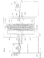
- Fig. 1 is a perspective view showing an outline of the present invention
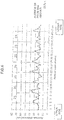
- Fig. 2 is a schematic view showing a liquid supply/discharge circuit and a control unit for electrolyte of the device shown in Fig. 1 .
- a rack 50 has right and left props 51a and 51b standing a predetermined height and spacing out a predetermined interval.
- Right and left holding frames 60 are supported at each center of the vertical direction (an axis direction of the hollow pipe) by the right and left props 51a and 51b of the rack 50 via a horizontal rotating axis 61.
- Flanges 111a and 111b are mounted in large diameter parts of the cells positioned at upper and lower ends of the hollow pipe 100.
- the flanges 111a and 111b are pinched by clips 201a and 201b attached to the holding frames 60, and thereby the flanges 111a and 111b are fixed on the holding frames 60.
- the hollow pipe 100 is set to the holding frames 60.
- the positions of fixing the hollow pipe 100 on the holding frames 60 are not limited to the upper and lower flanges 111a and 111b, if necessary, the hollow pipe 100 may be fixed on the holding frames 60 at any part to be reinforced by means of the same flanges and clips.
- the above described flanges 111a and 111b are divided into two parts in the diameter direction.
- the two divided flanges are connected each other with screws and so on at the diameter part of the cell of the hollow pipe 100, so that each flange 111a and 111b can be fixed on the hollow pipe 100.
- liquid buffers 300a and 300b are disposed using flanges 101a and 101b, and the liquid buffers 300a and 300b are respectively connected with circulation pipes 301 (a liquid supply pipe 301a and a liquid discharge pipe 301b that are described hereinafter).
- the two circulation pipes 301 are connected with a liquid tank 15 through a valve mechanism 302 and a pump 303.
- the valve mechanism 302 shown in Fig. 2 includes all valves illustrated in Fig. 3 described after, but the valve mechanism 302 in this embodiment means three-way valves 302a and 302b mainly.
- the circulation pipe 301 consists of the liquid supply pipe 301a and the liquid discharge pipe 301b, since the hollow pipe 100 is inverted upside down at a predetermined intervals as described later, a pipe on a side to be connected with the liquid buffer 300a at the lower end of the hollow pipe 100 becomes the liquid supply pipe 301a and the other pipe on the other side to be connected with the liquid buffer 300b at the upper end of the hollow pipe 100 becomes the liquid discharge pipe 301b.
- coupling members 70 for example, gear units connected with a motor for rotating the electrode 20 are arranged on both ends of an electrode axis 21 of the electrode 20.
- Fig 3 is a view more precisely showing the circuit for supplying the electrolyte to the hollow pipe 100 shown in Fig. 2 .
- Two ports of the 3-way valve 302a for supplying the liquid are connected each other so as to couple the liquid supply pipe 301a and the liquid discharge pipe 301b, and the other port of the 3-way valve 302a is connected with a liquid tank 15 through a pump 303.
- two port of the 3-way valve 302b for discharging the liquid are connected, in parallel to the 3-way valve 302a for supplying the liquid, so as to couple the liquid supply pipe 301a and the liquid discharge pipe 301b, and the other port of the 3-way vale 302b takes back the liquid to the liquid tank 15.
- a pure water tank 16 storing the pure water for cleaning is disposed separately, and a cleaning pipe 401 is connected with two ports of 3-way valve 402a for supplying the water so as to couple liquid buffers 300a and 300b.
- a cleaning pipe 401 is connected with two ports of 3-way valve 402a for supplying the water so as to couple liquid buffers 300a and 300b.
- two ports of 3-way valve 402b for discharging the water are connected so as to couple the two liquid buffers.
- the other port of the 3-way valve 402a for supplying the water is connected to the pure water tank 16 through a pump 403, and the other port of the 3-way valve 402b for discharging the water takes back the water to the pure water tank 16.
- the deteriorated electrolyte and the post-cleaning pure water are stored in a drainage tank 17.
- the liquid buffer 300a is connected to the liquid supply pipe 301a and the cleaning pipe 401 through 2-way valve 304a, and the liquid buffer 300b is connected to the liquid discharge pipe 301b and the cleaning pipe 401 through 2-way valve 304b.
- the 2-way valve 304a and the 2-way valve 304b are switched between the electrolytic treatment and the cleaning treatment.
- the hollow pipe 100 is fixed on the holding frames 60 by means of the clips 201a, 201b and the flanges 111a, 111b, and then the electrode 20 is inserted in the hollow pipe from the top of the hollow pipe 100.
- the structure of the electrode 20 is not limited in particular, but this embodiment uses the electrode disclosed in Japanese Patent No. 5,807,938 , since it needs to electro-polish a weld zone of the cell (the large diameter part, in particular).
- the upper and lower liquid buffer 300a and 300b are liquid-tightly attached on both ends of the hollow pipe 100, and the coupling members 70 set on the electrode axis 21 of the electrode 20 is coupled with the motor 71 that is a driving unit for rotating the electrode 20.
- each valve 302a, 302b constituting the valve mechanism 302 is set so as to circulate the electrolyte from the lower liquid buffer of the hollow pipe 100 to the upper liquid buffer, and then the electrolyte is supplied from the bottom of the hollow pipe 100 by the pump 303.
- the electrolytic treatment is started. While continuing to circulate a predetermined amount of the electrolyte per unit time, the electrolytic treatment is performed with a predetermined current for a predetermined period.
- the electrolytic treatment is carried out by applying a negative to the electrode 20 and a positive to the hollow pipe 100 while rotating the electrode 20 by the motor 71.
- the hollow pipe 100 is inversed together with the holding frames 100.
- valve mechanism 302 (the 3-way valve 302a and 302b) is switched so as to circulate the electrolyte from the lower liquid buffer 300a to the upper liquid buffer 300b, and then the electrolytic treatment is performed under the same conditions (time, current) as above.
- the valves constituting the valve mechanism 302 indicate all valves illustrated in Fig. 3 , such as the liquid supply valve 302a, the liquid discharge valve 302b, the water supply valve 402a, the water discharge valve 402b, and so on. In this embodiment, however, the valves to be switched for circulating the electrolyte are the liquid supply valve 302a and the liquid discharge valve 302b.
- the liquid discharge valve 302b changes to the liquid supply valve 302a while the liquid supply valve 302a changes to the liquid discharge valve 302b.
- “circulating the electrolyte upward from the below” it needs to switch the liquid supply valve 302a and the liquid discharge valve 302b.
- the above-mentioned electrolytic treatment can be carried out manually by inverting the hollow pipe 100, switching the valve mechanism 302, and controlling the required current and voltage, but these steps can be carried out automatically using a control unit 400.
- the control unit 400 inverts the hollow pipe and switches the supplying of the liquid, that is, it is sure to supply the electrolyte upward from the lower liquid buffer 300a and control the electrolytic treatment (time, current, and etc.).
- the electrolytic treatment is carried out for 3 minutes under 200 to 270 mA/cm 2 and around 16 to 17 V.
- the electrolyte treatment is called as one processing.
- the processing is carried out one more time after inverting the hollow pipe 100.
- the processing is repeated 31 times, which is called as a unit treatment.
- the amount of polishing at each measurement point in Fig. 5 is illustrated in Fig. 6 by the average of the plural unit treatments.
- the amount of polishing at the small diameter part is stable at about 20 ⁇ m, and the amount of polishing at the large diameter part is around 30 to 35 ⁇ m.
- the serial numbers are assigned from a top measurement point to a bottom measurement point in order (the same applies to Figs. 7 and 8 described hereinafter).
- Fig. 7 shows a result of a comparative example.
- the electrolytic treatment is suspended after the electrolytic treatment for a predetermined period (3 minutes) while supplying the electrolyte from the lower end of the hollow pipe 100, and then restarted after pushing out the bubbles dwelling around the shoulders of the cells while keeping supplying the electrolyte, of which treatment is repeated the same number of times as above. It is understood that the amount of polishing around the shoulder of the large diameter part becomes 80 to 90 ⁇ m, which differs 50 ⁇ m from the amount of polishing around the small diameter part.
- Fig. 8 shows a result of the other comparative example.
- the electrolytic treatment and the supply of the liquid are suspended temporarily after the electrolytic treatment for the predetermined period (3 minutes same as above) while supplying the electrolyte from the lower end, and then the electrolytic treatment is carried out while supplying the electrolyte from the upper side of the hollow pipe 100.
- the electrolytic treatment for the predetermined period (3 minutes) both the electrolytic treatment and the supply of the electrolyte is stopped, of which treatment is repeated the same number of times as above.
- the results of the treatments are show in Fig. 8 .
- the amount of polishing of the small diameter part is 20 to 25 ⁇ m, which does not differ greatly from a case of inverting the hollow pipe 100, but the amount of polishing of the large diameter part becomes 45 ⁇ m, and the difference between the amount of polishing of the large diameter part (the positions of the shoulders of the cells) and the amount of polishing of the small diameter parts becomes large.
- Fig. 9 shows photos by a microscope showing a weld zone (the large diameter part) on the inside of the hollow pipe before and after the treatment in the present invention.
- Fig. 6 shows the effect of the present invention according to the amount of polishing of each part.
- Fig. 9 shows that the inside of the hollow pipe 100 is finished as mirror-finished surface, and the state of the surface becomes smooth as expected.
- the bulge part (cell) of the hollow pipe 100 is formed as follows; cup-shaped bodies cutting into halves at the largest diameter part of the cell are coupled mutually, and the coupled parts are welded. Since the light to be irradiated is diffused before the treatment of the present invention ( Fig. 9(a) ), only an unclear picture can be obtained on the whole. After the treatment ( Fig. 9(b) ), however, it is understood that the surface are finished as mirror-finished surface, the debris at the weld zone is removed completely.
- the time for the electrolytic treatment before the inverse is the same as the time for the electrolytic treatment after the inverse, but it may be allowed to change the time of the electrolytic treatment depending on the conditions. For instance, there are cases that the upper side of the bulge is different in shape from the lower side of the bulge, or the upper side of the bulge is different in material from the lower side of the bulge.
- Awing electrode 22 is formed by arranging at least one or plural wings 22a, 22b ... (4 wings shown in Figure) in a circumferential direction of the electrode axis 21 at equal intervals, and an outer edge of the wing has a shape corresponding to an inner shape of the bulge of the hollow pipe 100 to be polished.
- Each wing 22a, 22b ... constituting the wing electrode 22 has the flexibility.
- the wing electrode 22 in such state can be housed in a housing tube 29 concentric with the electrode axis 21.
- the housing tube 29 is provided with a slit group 23 (slits 23a, 23b ...), and each slit 23a, 23b...is positioned so as to correspond to a tip of each wing 22a, 22b housed in the housing tube 29.
- the wings 22a, 22b ... are inserted in each slit 23a, 23b ... of the slit group 23 so as to slightly project each tip of the wings toward an outside of the housing tube 29.
- each diameter of the tips of wings 22a, 22b ... is adjustable (a diameter adjusting unit: the electrode axis 21+the wing electrode 22+the housing tube 29+the slit group 23).
- the wing electrode 22 changes to two modes, such as a housing state and a working state as mentioned hereinafter. Specifically, in the housing state, the tip of each wing 22a, 22b ... is slightly projected from each slit 23a, 23b ... of the housing tube 29, and in the working state as shown in Fig. 4 , each outer edge of the wing 22a, 22b ... is pushed out near to an internal peripheral surface of the hollow pipe 100 by relatively rotating the electrode axis 21 and the housing tube 29 (a distance between the outer edge of each wing 22a, 22b ... and the internal peripheral surface of the hollow pipe 100 is approximately 1 cm, for example).
- each wing Since at least the outer peripheral end of each wing is made of metal and electrically connected to the electrode axis 21, when an electric field is applied between the electrode 20 and the hollow pipe 100 in the working state, the inside of the hollow pipe 100 is electro-polished.
- the electrolytic polishing in the present invention is configured to perform the electrolytic polishing of the inside of the hollow pipe by inverting the hollow pipe repeatedly at the same time of pushing out the generated bubbles by circulating the electrolyte from the lower end of the hollow pipe, so that the inside can be polished evenly, and it is very effective to apply the invention to the product requiring precise polishing like the hollow pipe for the linear collider, in particular.
Landscapes
- Chemical & Material Sciences (AREA)
- Engineering & Computer Science (AREA)
- Chemical Kinetics & Catalysis (AREA)
- Electrochemistry (AREA)
- Materials Engineering (AREA)
- Metallurgy (AREA)
- Organic Chemistry (AREA)
- Electrical Discharge Machining, Electrochemical Machining, And Combined Machining (AREA)
Claims (5)
- Elektrolytische Poliervorrichtung, umfassend:ein Gerüst (50);Halterahmen (60) zum vertikalen Halten eines Hohlrohrs (100) und drehbar gestützt auf dem Gerüst, um vertikal um die vertikale Mitte des Hohlrohrs umkehrbar zu sein;eine in das Hohlrohr eingesetzte Elektrode (20);am oberen und unteren Ende des Hohlrohrs angeordnete Flüssigkeitspuffer (300a, 300b); undeinen Ventilmechanismus (302) zum Umwälzen eines Elektrolyts im Hohlraum von einem unteren Flüssigkeitspuffer zu einem oberen Flüssigkeitspuffer sowohl vor als auch nach dem Umkehren des umkehrbaren Hohlrohrs.
- Elektrolytische Poliervorrichtung nach Anspruch 1, ferner umfassend:
eine Steuereinheit (400) zum Durchführen des elektrolytischen Polierens für einen vorbestimmten Zeitraum während des Umwälzens des Elektrolyts im Hohlraum vom unteren Flüssigkeitspuffer nach Feststellen von einem Ende des Hohlrohrs nach unten und einem anderen Ende des Hohlrohrs nach oben und anschließend Durchführen des weiteren elektrolytischen Polierens für den vorbestimmten Zeitraum während des Umwälzens des Elektrolyts im Hohlrohr vom unteren Flüssigkeitspuffer nach Feststellen des anderen Endes des Hohlrohrs nach unten und des Endes des Hohlrohrs nach oben. - Elektrolytische Poliervorrichtung nach Anspruch 1, wobei
die Elektrode mehrere Flügelelektroden (22) umfasst, deren Form einer Innenseite des Hohlrohrs entspricht und einen Gehäusezustand des Wickelns der Flügelelektroden auf eine Elektrodenachse oder einem Betriebszustand des Abwickelns und Erstreckens der Flügelelektroden in einer Umfangsrichtung ändert. - Elektrolytische Poliervorrichtung nach Anspruch 1, wobei
das Hohlrohr ein Niobrohr mit regelmäßig angeordneten Erhebungen ist. - Elektrolytisches Polierverfahren unter Verwendung der elektrolytischen Poliervorrichtung nach Anspruch 1, umfassend die Schritte zum:Durchführen des elektrolytischen Polierens für einen vorbestimmten Zeitraum während des Umwälzens des Elektrolyts im Hohlrohr vom unteren Flüssigkeitspuffer zum oberen Flüssigkeitspuffer;Aussetzen des elektrolytischen Polierens und des Zuführens/Abführens des Elektrolyts;Umkehren des Hohlrohrs; undDurchführen des elektrolytischen Polierens des umgekehrten Hohlrohrs für den vorbestimmten Zeitraum während des Umwälzens des Elektrolyts im Hohlrohr vom unteren Flüssigkeitspuffer zum oberen Flüssigkeitspuffer.
Applications Claiming Priority (2)
| Application Number | Priority Date | Filing Date | Title |
|---|---|---|---|
| JP2018017023 | 2018-02-02 | ||
| PCT/JP2019/002257 WO2019151102A1 (ja) | 2018-02-02 | 2019-01-24 | 電解研磨方法および装置 |
Publications (3)
| Publication Number | Publication Date |
|---|---|
| EP3613877A1 EP3613877A1 (de) | 2020-02-26 |
| EP3613877A4 EP3613877A4 (de) | 2020-05-13 |
| EP3613877B1 true EP3613877B1 (de) | 2021-03-03 |
Family
ID=67478182
Family Applications (1)
| Application Number | Title | Priority Date | Filing Date |
|---|---|---|---|
| EP19747162.6A Active EP3613877B1 (de) | 2018-02-02 | 2019-01-24 | Verfahren und vorrichtung zum elektrolytischen polieren |
Country Status (5)
| Country | Link |
|---|---|
| US (1) | US11021807B2 (de) |
| EP (1) | EP3613877B1 (de) |
| JP (1) | JP7200141B2 (de) |
| CN (1) | CN110637108B (de) |
| WO (1) | WO2019151102A1 (de) |
Families Citing this family (4)
| Publication number | Priority date | Publication date | Assignee | Title |
|---|---|---|---|---|
| JP7036778B2 (ja) * | 2019-09-25 | 2022-03-15 | トーステ株式会社 | 金属管内面電解研磨方法、金属管内面電解研磨装置および金属管内面電解研磨装置の使用方法 |
| JP7483896B2 (ja) * | 2020-01-17 | 2024-05-15 | エショー バイオセラピー, インク. | オフターゲット毒性を低下させるプロ抗体 |
| JP7437016B2 (ja) * | 2020-02-03 | 2024-02-22 | マルイ鍍金工業株式会社 | 電解研磨方法および装置 |
| JP7471704B1 (ja) | 2023-08-17 | 2024-04-22 | 協和ステンレス株式会社 | ステンレスタンク用電解研磨装置、およびステンレスタンクの電解研磨方法 |
Family Cites Families (18)
| Publication number | Priority date | Publication date | Assignee | Title |
|---|---|---|---|---|
| CA947106A (en) | 1971-05-06 | 1974-05-14 | Measurex Corporation | Apparatus for measuring a characteristic of relatively thin sheet material |
| US3888755A (en) * | 1973-06-04 | 1975-06-10 | Bruce Evans Wallace | Cylinder plating rack |
| JPS60208496A (ja) * | 1984-04-03 | 1985-10-21 | Nippon Light Metal Co Ltd | アルミニウム又はアルミニウム合金中空体の内面を陽極酸化処理する方法 |
| JPS6123799A (ja) | 1984-07-10 | 1986-02-01 | Mitsubishi Heavy Ind Ltd | ニオブ中空体の電解研摩方法 |
| JPH08165600A (ja) * | 1994-12-14 | 1996-06-25 | Yamaguchi Seisakusho:Kk | ステンレス容器の内面研磨方法および装置 |
| JP2947270B1 (ja) | 1998-06-09 | 1999-09-13 | 株式会社野村鍍金 | 金属製中空体の内面研磨方法及び研磨装置 |
| US6547945B2 (en) * | 2000-07-31 | 2003-04-15 | United Technologies Corporation | Method and apparatuses for electrochemically treating an article |
| JP2002144152A (ja) * | 2000-11-14 | 2002-05-21 | Mitsubishi Heavy Ind Ltd | 丸棒試験片の電解研磨装置及び電解研磨方法 |
| TW572063U (en) * | 2001-11-28 | 2004-01-11 | Ind Tech Res Inst | An electropolishing process means for an inner surface of a long tube |
| CN2756647Y (zh) * | 2004-12-29 | 2006-02-08 | 锦西化工机械(集团)有限责任公司 | 细长管内表面电化学抛光装置 |
| US9006147B2 (en) * | 2012-07-11 | 2015-04-14 | Faraday Technology, Inc. | Electrochemical system and method for electropolishing superconductive radio frequency cavities |
| JP5807938B2 (ja) | 2012-07-11 | 2015-11-10 | マルイ鍍金工業株式会社 | 空洞管の研磨用電極とそれを用いた電解研磨方法 |
| JP6231835B2 (ja) * | 2013-09-20 | 2017-11-15 | マルイ鍍金工業株式会社 | 空洞管の電解研磨装置 |
| JP6231838B2 (ja) * | 2013-09-25 | 2017-11-15 | マルイ鍍金工業株式会社 | 空洞管の部分電解研磨治具と電解研磨方法 |
| JP6374724B2 (ja) * | 2014-07-30 | 2018-08-15 | マルイ鍍金工業株式会社 | 空洞管の研磨装置 |
| US10246792B2 (en) * | 2014-10-10 | 2019-04-02 | Marui Galvanizing Co., Ltd. | Rotor for polishing hollow tubes |
| JP6697947B2 (ja) * | 2016-05-12 | 2020-05-27 | 日本製鉄株式会社 | 電解研磨装置 |
| CN106400099B (zh) * | 2016-10-12 | 2018-04-17 | 福州大学 | 一种电子背散射衍射试样电解抛光装置 |
-
2019
- 2019-01-24 CN CN201980002441.6A patent/CN110637108B/zh active Active
- 2019-01-24 WO PCT/JP2019/002257 patent/WO2019151102A1/ja not_active Ceased
- 2019-01-24 US US16/612,814 patent/US11021807B2/en active Active
- 2019-01-24 JP JP2019569059A patent/JP7200141B2/ja active Active
- 2019-01-24 EP EP19747162.6A patent/EP3613877B1/de active Active
Non-Patent Citations (1)
| Title |
|---|
| None * |
Also Published As
| Publication number | Publication date |
|---|---|
| EP3613877A4 (de) | 2020-05-13 |
| CN110637108B (zh) | 2021-07-23 |
| US11021807B2 (en) | 2021-06-01 |
| JPWO2019151102A1 (ja) | 2021-09-09 |
| WO2019151102A1 (ja) | 2019-08-08 |
| CN110637108A (zh) | 2019-12-31 |
| US20200199771A1 (en) | 2020-06-25 |
| EP3613877A1 (de) | 2020-02-26 |
| JP7200141B2 (ja) | 2023-01-06 |
Similar Documents
| Publication | Publication Date | Title |
|---|---|---|
| EP3613877A1 (de) | Verfahren und vorrichtung zum elektrolytischen polieren | |
| US9689086B2 (en) | Electrode for polishing hollow tube, and electrolytic polishing method using same | |
| EP0393192A4 (en) | Device for electrochemical treatment of articles | |
| KR20090101682A (ko) | 금속 테이프의 전해 연마를 위한 장치 및 방법 | |
| US10246792B2 (en) | Rotor for polishing hollow tubes | |
| KR101278711B1 (ko) | 반도체 웨이퍼 도금 장치 및 이를 이용한 도금 방법 | |
| JP7437016B2 (ja) | 電解研磨方法および装置 | |
| JP4212081B2 (ja) | 連続湿式処理方法及び装置並びに液シール方法及び装置 | |
| JP6231835B2 (ja) | 空洞管の電解研磨装置 | |
| CN107641831A (zh) | 钕铁硼产品电泳前自动化处理的装置及方法 | |
| JP2001196343A (ja) | 基板処理装置 | |
| JP2018154889A (ja) | 電解処理装置および方法 | |
| KR20130091069A (ko) | 전해 연마장치 | |
| JP5631567B2 (ja) | 電気めっきにより被膜を工作物に被着させる装置及び方法 | |
| KR100941650B1 (ko) | 롤러타입 전해연마장치 | |
| JP5187673B1 (ja) | 金属製円筒状ローラーのメッキ装置 | |
| JPS62243800A (ja) | 電解研摩によるテ−パワイヤの製造方法 | |
| RU102009U1 (ru) | Установка для проточного железнения внешних поверхностей деталей типа "вал" | |
| JP2024135660A (ja) | 電解研磨システム | |
| KR20090097558A (ko) | 슬로프 타입 전해연마장치 | |
| KR100351995B1 (ko) | 전해연마장치 | |
| JPH0222499A (ja) | メッキ装置 | |
| SU1461775A1 (ru) | Агрегат электрохимической обработки проволоки | |
| JPS5843475B2 (ja) | 細管の内壁に対する皮膜形成方法およびその装置 | |
| JPH06192884A (ja) | 微小部表面処理装置 |
Legal Events
| Date | Code | Title | Description |
|---|---|---|---|
| STAA | Information on the status of an ep patent application or granted ep patent |
Free format text: STATUS: THE INTERNATIONAL PUBLICATION HAS BEEN MADE |
|
| PUAI | Public reference made under article 153(3) epc to a published international application that has entered the european phase |
Free format text: ORIGINAL CODE: 0009012 |
|
| STAA | Information on the status of an ep patent application or granted ep patent |
Free format text: STATUS: REQUEST FOR EXAMINATION WAS MADE |
|
| 17P | Request for examination filed |
Effective date: 20191030 |
|
| AK | Designated contracting states |
Kind code of ref document: A1 Designated state(s): AL AT BE BG CH CY CZ DE DK EE ES FI FR GB GR HR HU IE IS IT LI LT LU LV MC MK MT NL NO PL PT RO RS SE SI SK SM TR |
|
| AX | Request for extension of the european patent |
Extension state: BA ME |
|
| A4 | Supplementary search report drawn up and despatched |
Effective date: 20200415 |
|
| RIC1 | Information provided on ipc code assigned before grant |
Ipc: C25F 7/00 20060101AFI20200407BHEP Ipc: C25F 3/16 20060101ALI20200407BHEP |
|
| GRAP | Despatch of communication of intention to grant a patent |
Free format text: ORIGINAL CODE: EPIDOSNIGR1 |
|
| STAA | Information on the status of an ep patent application or granted ep patent |
Free format text: STATUS: GRANT OF PATENT IS INTENDED |
|
| DAV | Request for validation of the european patent (deleted) | ||
| DAX | Request for extension of the european patent (deleted) | ||
| INTG | Intention to grant announced |
Effective date: 20201007 |
|
| GRAS | Grant fee paid |
Free format text: ORIGINAL CODE: EPIDOSNIGR3 |
|
| GRAA | (expected) grant |
Free format text: ORIGINAL CODE: 0009210 |
|
| STAA | Information on the status of an ep patent application or granted ep patent |
Free format text: STATUS: THE PATENT HAS BEEN GRANTED |
|
| AK | Designated contracting states |
Kind code of ref document: B1 Designated state(s): AL AT BE BG CH CY CZ DE DK EE ES FI FR GB GR HR HU IE IS IT LI LT LU LV MC MK MT NL NO PL PT RO RS SE SI SK SM TR |
|
| REG | Reference to a national code |
Ref country code: GB Ref legal event code: FG4D |
|
| REG | Reference to a national code |
Ref country code: CH Ref legal event code: EP Ref country code: CH Ref legal event code: NV Representative=s name: BOVARD AG PATENT- UND MARKENANWAELTE, CH Ref country code: AT Ref legal event code: REF Ref document number: 1367292 Country of ref document: AT Kind code of ref document: T Effective date: 20210315 |
|
| REG | Reference to a national code |
Ref country code: DE Ref legal event code: R096 Ref document number: 602019002967 Country of ref document: DE |
|
| REG | Reference to a national code |
Ref country code: IE Ref legal event code: FG4D |
|
| REG | Reference to a national code |
Ref country code: LT Ref legal event code: MG9D |
|
| PG25 | Lapsed in a contracting state [announced via postgrant information from national office to epo] |
Ref country code: GR Free format text: LAPSE BECAUSE OF FAILURE TO SUBMIT A TRANSLATION OF THE DESCRIPTION OR TO PAY THE FEE WITHIN THE PRESCRIBED TIME-LIMIT Effective date: 20210604 Ref country code: FI Free format text: LAPSE BECAUSE OF FAILURE TO SUBMIT A TRANSLATION OF THE DESCRIPTION OR TO PAY THE FEE WITHIN THE PRESCRIBED TIME-LIMIT Effective date: 20210303 Ref country code: BG Free format text: LAPSE BECAUSE OF FAILURE TO SUBMIT A TRANSLATION OF THE DESCRIPTION OR TO PAY THE FEE WITHIN THE PRESCRIBED TIME-LIMIT Effective date: 20210603 Ref country code: HR Free format text: LAPSE BECAUSE OF FAILURE TO SUBMIT A TRANSLATION OF THE DESCRIPTION OR TO PAY THE FEE WITHIN THE PRESCRIBED TIME-LIMIT Effective date: 20210303 Ref country code: NO Free format text: LAPSE BECAUSE OF FAILURE TO SUBMIT A TRANSLATION OF THE DESCRIPTION OR TO PAY THE FEE WITHIN THE PRESCRIBED TIME-LIMIT Effective date: 20210603 Ref country code: LT Free format text: LAPSE BECAUSE OF FAILURE TO SUBMIT A TRANSLATION OF THE DESCRIPTION OR TO PAY THE FEE WITHIN THE PRESCRIBED TIME-LIMIT Effective date: 20210303 |
|
| REG | Reference to a national code |
Ref country code: NL Ref legal event code: MP Effective date: 20210303 |
|
| REG | Reference to a national code |
Ref country code: AT Ref legal event code: MK05 Ref document number: 1367292 Country of ref document: AT Kind code of ref document: T Effective date: 20210303 |
|
| PG25 | Lapsed in a contracting state [announced via postgrant information from national office to epo] |
Ref country code: LV Free format text: LAPSE BECAUSE OF FAILURE TO SUBMIT A TRANSLATION OF THE DESCRIPTION OR TO PAY THE FEE WITHIN THE PRESCRIBED TIME-LIMIT Effective date: 20210303 Ref country code: PL Free format text: LAPSE BECAUSE OF FAILURE TO SUBMIT A TRANSLATION OF THE DESCRIPTION OR TO PAY THE FEE WITHIN THE PRESCRIBED TIME-LIMIT Effective date: 20210303 Ref country code: RS Free format text: LAPSE BECAUSE OF FAILURE TO SUBMIT A TRANSLATION OF THE DESCRIPTION OR TO PAY THE FEE WITHIN THE PRESCRIBED TIME-LIMIT Effective date: 20210303 Ref country code: SE Free format text: LAPSE BECAUSE OF FAILURE TO SUBMIT A TRANSLATION OF THE DESCRIPTION OR TO PAY THE FEE WITHIN THE PRESCRIBED TIME-LIMIT Effective date: 20210303 |
|
| PG25 | Lapsed in a contracting state [announced via postgrant information from national office to epo] |
Ref country code: NL Free format text: LAPSE BECAUSE OF FAILURE TO SUBMIT A TRANSLATION OF THE DESCRIPTION OR TO PAY THE FEE WITHIN THE PRESCRIBED TIME-LIMIT Effective date: 20210303 |
|
| PG25 | Lapsed in a contracting state [announced via postgrant information from national office to epo] |
Ref country code: SM Free format text: LAPSE BECAUSE OF FAILURE TO SUBMIT A TRANSLATION OF THE DESCRIPTION OR TO PAY THE FEE WITHIN THE PRESCRIBED TIME-LIMIT Effective date: 20210303 Ref country code: AT Free format text: LAPSE BECAUSE OF FAILURE TO SUBMIT A TRANSLATION OF THE DESCRIPTION OR TO PAY THE FEE WITHIN THE PRESCRIBED TIME-LIMIT Effective date: 20210303 Ref country code: EE Free format text: LAPSE BECAUSE OF FAILURE TO SUBMIT A TRANSLATION OF THE DESCRIPTION OR TO PAY THE FEE WITHIN THE PRESCRIBED TIME-LIMIT Effective date: 20210303 Ref country code: CZ Free format text: LAPSE BECAUSE OF FAILURE TO SUBMIT A TRANSLATION OF THE DESCRIPTION OR TO PAY THE FEE WITHIN THE PRESCRIBED TIME-LIMIT Effective date: 20210303 |
|
| PG25 | Lapsed in a contracting state [announced via postgrant information from national office to epo] |
Ref country code: IS Free format text: LAPSE BECAUSE OF FAILURE TO SUBMIT A TRANSLATION OF THE DESCRIPTION OR TO PAY THE FEE WITHIN THE PRESCRIBED TIME-LIMIT Effective date: 20210703 Ref country code: SK Free format text: LAPSE BECAUSE OF FAILURE TO SUBMIT A TRANSLATION OF THE DESCRIPTION OR TO PAY THE FEE WITHIN THE PRESCRIBED TIME-LIMIT Effective date: 20210303 Ref country code: PT Free format text: LAPSE BECAUSE OF FAILURE TO SUBMIT A TRANSLATION OF THE DESCRIPTION OR TO PAY THE FEE WITHIN THE PRESCRIBED TIME-LIMIT Effective date: 20210705 Ref country code: RO Free format text: LAPSE BECAUSE OF FAILURE TO SUBMIT A TRANSLATION OF THE DESCRIPTION OR TO PAY THE FEE WITHIN THE PRESCRIBED TIME-LIMIT Effective date: 20210303 |
|
| REG | Reference to a national code |
Ref country code: DE Ref legal event code: R097 Ref document number: 602019002967 Country of ref document: DE |
|
| PLBE | No opposition filed within time limit |
Free format text: ORIGINAL CODE: 0009261 |
|
| STAA | Information on the status of an ep patent application or granted ep patent |
Free format text: STATUS: NO OPPOSITION FILED WITHIN TIME LIMIT |
|
| PG25 | Lapsed in a contracting state [announced via postgrant information from national office to epo] |
Ref country code: ES Free format text: LAPSE BECAUSE OF FAILURE TO SUBMIT A TRANSLATION OF THE DESCRIPTION OR TO PAY THE FEE WITHIN THE PRESCRIBED TIME-LIMIT Effective date: 20210303 Ref country code: DK Free format text: LAPSE BECAUSE OF FAILURE TO SUBMIT A TRANSLATION OF THE DESCRIPTION OR TO PAY THE FEE WITHIN THE PRESCRIBED TIME-LIMIT Effective date: 20210303 Ref country code: AL Free format text: LAPSE BECAUSE OF FAILURE TO SUBMIT A TRANSLATION OF THE DESCRIPTION OR TO PAY THE FEE WITHIN THE PRESCRIBED TIME-LIMIT Effective date: 20210303 |
|
| 26N | No opposition filed |
Effective date: 20211206 |
|
| PG25 | Lapsed in a contracting state [announced via postgrant information from national office to epo] |
Ref country code: SI Free format text: LAPSE BECAUSE OF FAILURE TO SUBMIT A TRANSLATION OF THE DESCRIPTION OR TO PAY THE FEE WITHIN THE PRESCRIBED TIME-LIMIT Effective date: 20210303 |
|
| PG25 | Lapsed in a contracting state [announced via postgrant information from national office to epo] |
Ref country code: IT Free format text: LAPSE BECAUSE OF FAILURE TO SUBMIT A TRANSLATION OF THE DESCRIPTION OR TO PAY THE FEE WITHIN THE PRESCRIBED TIME-LIMIT Effective date: 20210303 |
|
| PG25 | Lapsed in a contracting state [announced via postgrant information from national office to epo] |
Ref country code: IS Free format text: LAPSE BECAUSE OF FAILURE TO SUBMIT A TRANSLATION OF THE DESCRIPTION OR TO PAY THE FEE WITHIN THE PRESCRIBED TIME-LIMIT Effective date: 20210703 |
|
| PG25 | Lapsed in a contracting state [announced via postgrant information from national office to epo] |
Ref country code: MC Free format text: LAPSE BECAUSE OF FAILURE TO SUBMIT A TRANSLATION OF THE DESCRIPTION OR TO PAY THE FEE WITHIN THE PRESCRIBED TIME-LIMIT Effective date: 20210303 |
|
| REG | Reference to a national code |
Ref country code: BE Ref legal event code: MM Effective date: 20220131 |
|
| PG25 | Lapsed in a contracting state [announced via postgrant information from national office to epo] |
Ref country code: LU Free format text: LAPSE BECAUSE OF NON-PAYMENT OF DUE FEES Effective date: 20220124 |
|
| PG25 | Lapsed in a contracting state [announced via postgrant information from national office to epo] |
Ref country code: BE Free format text: LAPSE BECAUSE OF NON-PAYMENT OF DUE FEES Effective date: 20220131 |
|
| PG25 | Lapsed in a contracting state [announced via postgrant information from national office to epo] |
Ref country code: IE Free format text: LAPSE BECAUSE OF NON-PAYMENT OF DUE FEES Effective date: 20220124 |
|
| PG25 | Lapsed in a contracting state [announced via postgrant information from national office to epo] |
Ref country code: MK Free format text: LAPSE BECAUSE OF FAILURE TO SUBMIT A TRANSLATION OF THE DESCRIPTION OR TO PAY THE FEE WITHIN THE PRESCRIBED TIME-LIMIT Effective date: 20210303 Ref country code: CY Free format text: LAPSE BECAUSE OF FAILURE TO SUBMIT A TRANSLATION OF THE DESCRIPTION OR TO PAY THE FEE WITHIN THE PRESCRIBED TIME-LIMIT Effective date: 20210303 |
|
| PG25 | Lapsed in a contracting state [announced via postgrant information from national office to epo] |
Ref country code: HU Free format text: LAPSE BECAUSE OF FAILURE TO SUBMIT A TRANSLATION OF THE DESCRIPTION OR TO PAY THE FEE WITHIN THE PRESCRIBED TIME-LIMIT; INVALID AB INITIO Effective date: 20190124 |
|
| PG25 | Lapsed in a contracting state [announced via postgrant information from national office to epo] |
Ref country code: MT Free format text: LAPSE BECAUSE OF FAILURE TO SUBMIT A TRANSLATION OF THE DESCRIPTION OR TO PAY THE FEE WITHIN THE PRESCRIBED TIME-LIMIT Effective date: 20210303 |
|
| PG25 | Lapsed in a contracting state [announced via postgrant information from national office to epo] |
Ref country code: TR Free format text: LAPSE BECAUSE OF FAILURE TO SUBMIT A TRANSLATION OF THE DESCRIPTION OR TO PAY THE FEE WITHIN THE PRESCRIBED TIME-LIMIT Effective date: 20210303 |
|
| REG | Reference to a national code |
Ref country code: CH Ref legal event code: U11 Free format text: ST27 STATUS EVENT CODE: U-0-0-U10-U11 (AS PROVIDED BY THE NATIONAL OFFICE) Effective date: 20260201 |
|
| PGFP | Annual fee paid to national office [announced via postgrant information from national office to epo] |
Ref country code: GB Payment date: 20260121 Year of fee payment: 8 |
|
| PGFP | Annual fee paid to national office [announced via postgrant information from national office to epo] |
Ref country code: DE Payment date: 20260128 Year of fee payment: 8 |
|
| PGFP | Annual fee paid to national office [announced via postgrant information from national office to epo] |
Ref country code: FR Payment date: 20260123 Year of fee payment: 8 |
|
| PGFP | Annual fee paid to national office [announced via postgrant information from national office to epo] |
Ref country code: CH Payment date: 20260201 Year of fee payment: 8 |