EP3611058B9 - Strukturelement für automobile - Google Patents
Strukturelement für automobile Download PDFInfo
- Publication number
- EP3611058B9 EP3611058B9 EP18784350.3A EP18784350A EP3611058B9 EP 3611058 B9 EP3611058 B9 EP 3611058B9 EP 18784350 A EP18784350 A EP 18784350A EP 3611058 B9 EP3611058 B9 EP 3611058B9
- Authority
- EP
- European Patent Office
- Prior art keywords
- press
- formed product
- reinforcing member
- vertical wall
- plate
- Prior art date
- Legal status (The legal status is an assumption and is not a legal conclusion. Google has not performed a legal analysis and makes no representation as to the accuracy of the status listed.)
- Active
Links
Images


Classifications
-
- B—PERFORMING OPERATIONS; TRANSPORTING
- B62—LAND VEHICLES FOR TRAVELLING OTHERWISE THAN ON RAILS
- B62D—MOTOR VEHICLES; TRAILERS
- B62D25/00—Superstructure or monocoque structure sub-units; Parts or details thereof not otherwise provided for
-
- B—PERFORMING OPERATIONS; TRANSPORTING
- B60—VEHICLES IN GENERAL
- B60J—WINDOWS, WINDSCREENS, NON-FIXED ROOFS, DOORS, OR SIMILAR DEVICES FOR VEHICLES; REMOVABLE EXTERNAL PROTECTIVE COVERINGS SPECIALLY ADAPTED FOR VEHICLES
- B60J5/00—Doors
-
- B—PERFORMING OPERATIONS; TRANSPORTING
- B60—VEHICLES IN GENERAL
- B60R—VEHICLES, VEHICLE FITTINGS, OR VEHICLE PARTS, NOT OTHERWISE PROVIDED FOR
- B60R19/00—Wheel guards; Radiator guards, e.g. grilles; Obstruction removers; Fittings damping bouncing force in collisions
- B60R19/02—Bumpers, i.e. impact receiving or absorbing members for protecting vehicles or fending off blows from other vehicles or objects
- B60R19/04—Bumpers, i.e. impact receiving or absorbing members for protecting vehicles or fending off blows from other vehicles or objects formed from more than one section in a side-by-side arrangement
-
- B—PERFORMING OPERATIONS; TRANSPORTING
- B62—LAND VEHICLES FOR TRAVELLING OTHERWISE THAN ON RAILS
- B62D—MOTOR VEHICLES; TRAILERS
- B62D21/00—Understructures, i.e. chassis frame on which a vehicle body may be mounted
-
- B—PERFORMING OPERATIONS; TRANSPORTING
- B62—LAND VEHICLES FOR TRAVELLING OTHERWISE THAN ON RAILS
- B62D—MOTOR VEHICLES; TRAILERS
- B62D25/00—Superstructure or monocoque structure sub-units; Parts or details thereof not otherwise provided for
- B62D25/02—Side panels
- B62D25/025—Side sills thereof
-
- E—FIXED CONSTRUCTIONS
- E04—BUILDING
- E04C—STRUCTURAL ELEMENTS; BUILDING MATERIALS
- E04C5/00—Reinforcing elements, e.g. for concrete; Auxiliary elements therefor
- E04C5/01—Reinforcing elements of metal, e.g. with non-structural coatings
- E04C5/06—Reinforcing elements of metal, e.g. with non-structural coatings of high bending resistance, i.e. of essentially three-dimensional [3D] extent, e.g. lattice girders
-
- B—PERFORMING OPERATIONS; TRANSPORTING
- B60—VEHICLES IN GENERAL
- B60R—VEHICLES, VEHICLE FITTINGS, OR VEHICLE PARTS, NOT OTHERWISE PROVIDED FOR
- B60R19/00—Wheel guards; Radiator guards, e.g. grilles; Obstruction removers; Fittings damping bouncing force in collisions
- B60R19/02—Bumpers, i.e. impact receiving or absorbing members for protecting vehicles or fending off blows from other vehicles or objects
- B60R19/18—Bumpers, i.e. impact receiving or absorbing members for protecting vehicles or fending off blows from other vehicles or objects characterised by the cross-section; Means within the bumper to absorb impact
- B60R2019/1806—Structural beams therefor, e.g. shock-absorbing
- B60R2019/1813—Structural beams therefor, e.g. shock-absorbing made of metal
-
- B—PERFORMING OPERATIONS; TRANSPORTING
- B62—LAND VEHICLES FOR TRAVELLING OTHERWISE THAN ON RAILS
- B62D—MOTOR VEHICLES; TRAILERS
- B62D25/00—Superstructure or monocoque structure sub-units; Parts or details thereof not otherwise provided for
- B62D25/04—Door pillars ; windshield pillars
-
- B—PERFORMING OPERATIONS; TRANSPORTING
- B62—LAND VEHICLES FOR TRAVELLING OTHERWISE THAN ON RAILS
- B62D—MOTOR VEHICLES; TRAILERS
- B62D25/00—Superstructure or monocoque structure sub-units; Parts or details thereof not otherwise provided for
- B62D25/06—Fixed roofs
-
- B—PERFORMING OPERATIONS; TRANSPORTING
- B62—LAND VEHICLES FOR TRAVELLING OTHERWISE THAN ON RAILS
- B62D—MOTOR VEHICLES; TRAILERS
- B62D25/00—Superstructure or monocoque structure sub-units; Parts or details thereof not otherwise provided for
- B62D25/20—Floors or bottom sub-units
Definitions
- Patent Literature 1 discloses a frame structure including a tubular frame body. A reinforcing member is attached to the inner side of a corner portion of the frame body.
- Patent Literature 4 discloses a structural member in which a hollow cross section is formed by a top wall portion, vertical wall portions respectively linked with both ends of the top wall portion, and a bottom wall portion. A bulging portion bulging outward is provided in a connection region between the top wall portion and the vertical wall portion.
- Patent Literature 5 discloses a reinforcing structure of a collision energy absorbing member of an automobile, such as a front side member of the automobile, having a U-shaped cross section having an opened end. A clip-shaped patch member is inserted into a portion which is predicted to deform most on an opened end side of the member when impact force of a longitudinal direction is applied.
- Patent Literature 6 discloses a hollow beam, for example, for mounting a trailer hitch.
- the hollow beam includes provisions to allow mounting a spacer sleeve or support body in its intended location for insertion of a mounting bolt from outside the beam.
- the sleeve at least partially encompasses the mounting bolt and is inserted through an access opening into the hollow beam and is subsequently positioned in registration with attachment holes and which receive the mounting bolt.
- a structural member according to an embodiment of the present invention is a structural member for an automobile.
- This structural member includes a press-formed product formed from one steel sheet and a reinforcing member fixed to the press-formed product.
- the press-formed product includes two vertical wall portions and a top plate portion linking the two vertical wall portions.
- the reinforcing member is a member which has an L-shaped cross section and includes a first plate-like portion and a second plate-like portion.
- the first plate-like portion is fixed, by at least one kind selected from the group consisting of welding, adhesive bonding, brazing, riveting, and friction stir joining, to one of the vertical wall portions such that the second plate-like portion protrudes toward an outward direction from a side of the vertical wall portion along the top plate portion.
- a cross section at a boundary between the vertical wall portion and the top plate portion has a rounded shape, and the second plate-like portion is disposed on a top plate portion side with respect to a starting position of the rounded shape in the vertical wall portion
- the present invention it is possible to achieve a structural member having high properties in a three-point bending test.
- Using the structural member according to the present invention enables improvement of collision safety performance of an automobile and reduction of the weight thereof.
- cross section refers to, unless otherwise stated, a cross section perpendicular to a direction in which a press-formed product (P) extends (longitudinal direction).
- the press-formed product (P) includes two vertical wall portions, and a top plate portion linking the two vertical wall portions.
- the reinforcing member (R) is a member which has an L-shaped cross section and includes a first plate-like portion and a second plate-like portion. The first plate-like portion is fixed to one of the vertical wall portions such that the second plate-like portion protrudes toward an outward direction from a side of the vertical wall portion along the top plate portion.
- the press-formed product (P) can be formed by deforming one steel sheet (blank steel sheet).
- the cross section of the press-formed product (P) may include a U-shaped portion whose bottom portion is substantially flat.
- its cross section may be substantially hat-shaped.
- the press-formed product (P) has a generally elongated shape. Any of the vertical wall portions, the top plate portion, and the flange portions to be described below extends along the longitudinal direction of the press-formed product (P).
- the reinforcing member (R) may be disposed over the entire press-formed product (P) in the longitudinal direction, or may be disposed over only a part of the press-formed product (P) in the longitudinal direction.
- the first plate-like portion is fixed to the press-formed product (P) such that the side thereof which is linked to the second plate-like portion is disposed upward (on the top plate portion side).
- the way in which the first plate-like portion of the reinforcing member (R) is fixed to the press-formed product (P) may be selected depending on the circumstances.
- the first plate-like portion is fixed to the press-formed product (P) by at least one kind selected from the group consisting of welding, adhesive bonding, brazing, riveting, and friction stir joining. Examples of welding include resistance spot welding and laser welding.
- the shape, range, and number of the fixing portion may be appropriately selected depending on the circumstances. Regarding the position of the fixing portion, it is preferably as close to the top plate portion as possible.
- the reinforcing member (R) may be fixed only to the press-formed product (P). That is, the reinforcing member (R) may not be fixed to any member other than the press-formed product (P).
- the structural member (S) of the present embodiment may be a bumper beam, a side sill, a center pillar, an A pillar, a roof rail, a door impact beam, a beltline reinforcement, or a roof arch.
- the structural member (S) may be used as another structural member for an automobile.
- the structural member (S) may be a component that undergoes bending deformation upon collision.
- the structural member (S) of the present embodiment may include another reinforcing member in addition to the reinforcing member (R).
- a reinforcing member having a cross section of an L-shape may be fixed to the press-formed product (P) so as to lie along the inside of the corner portion (corner portion at a boundary between the top plate portion and the vertical wall portion) of the press-formed product (P).
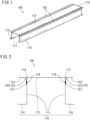
- FIG. 1 A perspective view of one example of the structural member (S) of the present embodiment is schematically shown in FIG. 1 .
- a structural member 100 of FIG. 1 includes a press-formed product 110, and two reinforcing members 120 fixed to the press-formed product 110.
- the press-formed product 110 is one example of the above-described press-formed product (P).
- Each reinforcing member 120 is one example of the above-described reinforcing member (R).
- the press-formed product 110 includes two vertical wall portions 111 and a top plate portion 112 linking the two vertical wall portions 111.
- a ridge portion at a boundary between each vertical wall portion 111 and the top plate portion 112 may be referred to as a corner portion 113.
- the press-formed product 110 further includes two flange portions 114 which extend from ends of the two vertical wall portions 111.
- the additional member (M) may be fixed to the flange portions 114.
- the two flange portions 114 extend from lower end portions of the two vertical wall portions 111 substantially horizontally toward outward. That is, the flange portions 114 and the top plate portion 112 are substantially parallel with each other.
- the angle X is an angle shown in FIG. 3 of the angles formed by a plane 112s including the top plate portion 112 and a plane 122s including the second plate-like portion 122. To be more specific, it is an angle located above the top plate portion 112 and the second plate-like portion 122 in FIG. 3 out of the angles formed by the plane 112s and the plane 122s.
- the angle X may be within the above-described range.
- a major plane of the top plate portion (this plane is a plane which is substantially parallel with a virtual plane connecting the ends of the vertical wall portions) can be considered as a plane 112s including the top plate portion 112.
- FIG. 3 shows an angle Y formed by the vertical wall portion 111 and the top plate portion 112.
- the angle Y is an angle on the inner side of the press-formed product 110 out of the angles formed by the vertical wall portion 111 and the top plate portion 112.
- the angle Y may be within the above-described range.
- FIG. 3 shows an angle Z formed by the first plate-like portion 121 and the second plate-like portion 122.
- the angle Z is a smaller angle out of the angles formed by the first plate-like portion 121 and the second plate-like portion 122.
- the angle Z may be within the above-described range.
- the radius of curvature of the corner portion 113 of the press-formed product 110 is often not more than 20 mm. Therefore, the distance D between the first virtual plane 112s and the second plate-like portion 122 is preferably not more than 20 mm.
- the distance D is preferably 0 to 10 mm, more preferably 0 to 5 mm, further preferably 0 to 3 mm, and most preferably 0 to 1 mm.
- the shorter the distance D the more quickly the reinforcing member 120 can come into contact with a collision object (an impactor) upon collision. Since this allows early generation of force to press the vertical wall portion 111 inwardly with the reinforcing member 120 before the vertical wall portion 111 falls outwardly, anti-collision properties will be improved.
- the radius of curvature of the corner portion 123 of the reinforcing member 120 is preferably less than 50% of the entire length of the reinforcing member 120 in a cross-sectional view of the reinforcing member 120. If the radius of curvature of the corner portion 123 is not less than 50% of the entire length in a cross-sectional view of the reinforcing member 120, it is difficult to ensure sufficient lengths in a cross-sectional view of the first plate-like portion 121 and the second plate-like portion 122 of the reinforcing member 120. For that reason, a preferable upper limit of the radius of curvature of the corner portion 123 of the reinforcing member 120 is 50% of the entire length in a cross-sectional view of the reinforcing member 120.
- the radius of curvature of the corner portion 123 of the reinforcing member 120 is preferably more than 3 mm. Moreover, the radius of curvature of the corner portion 123 of the reinforcing member 120 is preferably less than 10 mm.
- the distance D between the first virtual plane 112s and the second plate-like portion 122 is supposed to be the distance in the virtual plane vertical direction between the starting position (end point of R) 123b of the rounded shape on the second plate-like portion 122 side of the corner portion 123 and the first virtual plane 112s.
- a projection region of the reinforcing member 120 lies in a range of a projection region of the press-formed product 110.
- the second plate-like portion 122 is disposed between the plane 112s and the plane 113as. Since the structural member 100 becomes compact according to such configuration, the structural member 100 is less likely to interfere with other components. The less likeliness of the structural member 100 interfering with other components means the less likeliness of the reinforcing member 120 interfering with other components. If the reinforcing member 120 is brought into contact with an additional member when load is applied to the structural member, the force with which the reinforcing member 120 causes the vertical wall portion 111 of the press-formed product 110 to fall inwardly decreases. Therefore, the projection region of the reinforcing member 120 preferably lies in a range of the projection region of the press-formed product 110.
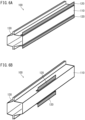
- FIGS. 6A and 6B An example in which the structural member of the present embodiment is a side sill is schematically shown by perspective views of FIGS. 6A and 6B .
- the reinforcing member 120 is indicated by a gray color in FIGS. 6A and 6B , and FIG. 7A to be described below.
- the structural members (side sills) 100 shown in FIGS. 6A and 6B each include a press-formed product 110, two reinforcing members 120, and an additional member 130.
- each reinforcing member 120 is disposed over the entire press-formed product 110 in the longitudinal direction.
- each reinforcing member 120 may be disposed over only a part of the press-formed product 110 in the longitudinal direction.
- the reinforcing member 120 may be disposed over only a part of the longitudinal direction of the press-formed product 110.
- the bumper beam has its two ends in the longitudinal direction attached to a crash box, etc. For that reason, the middle of the longitudinal direction of the bumper beam is most likely to be deflected.
- providing the reinforcing member 120 only in the middle of the structural member 100 can reinforce the middle of the bumper beam where strength is required most.
- by providing the reinforcing member 120 only at a location where strength is required it is possible to achieve both improvement in strength and reduction of weight of the structural member 100.
- the reinforcing member 120 is provided at a part of the longitudinal direction of the press-formed product 110, when the entire length in the longitudinal direction of the press-formed product 110 is denoted as L, it is preferable that the reinforcing member 120 is provided in a region up to a distance of L/6 to both sides from the middle of the longitudinal direction of the press-formed product 110 (a region of L/3 as a whole).
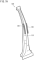
- FIG. 7A An example in which the structural member of the present embodiment is a center pillar is schematically shown by a perspective view of FIG. 7A .
- the structural member (center pillar) 100 shown in FIG. 7A includes a press-formed product 110 and two reinforcing members 120.
- the reinforcing members 120 are disposed over only a part of the press-formed product 110 in the longitudinal direction.
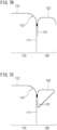
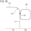
- FIGS. 7B to 7D Examples of the cross-sectional shape of the reinforcing member 120 of the present embodiment are shown in FIGS. 7B to 7D .
- the cross-sectional shape of the reinforcing member 120 may be a U-shape linking three straight sides.
- the cross-sectional shape of the reinforcing member 120 may be a triangular shape.
- the cross-sectional shape of the reinforcing member 120 may be a rectangular shape. That is, the reinforcing member 120 may include any plate-like portion other than the first plate-like portion 121 and the second plate-like portion 122, or may not include the any plate-like portion. In any of FIGS.
- the reinforcing member 120 when load is applied to the top plate portion 112 of the press-formed product 110, the reinforcing member 120 can make the vertical wall portion 111 of the press-formed product 110 fall inwardly, thus achieving effects by the structural member of the present embodiment.
- Example 1 simulation of a three-point bending test was conducted on a structural member of the present embodiment (Inventive Example) and a structural member of Comparative Example.
- a general-purpose FEM (finite element method) software supplied by Livermore Software Technology Corporation, Product Name: LS-DYNA was used for the simulation.
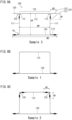
- a cross-sectional view of Sample 3 (Inventive Example) used in the simulation is schematically shown in FIG. 8A .
- the structural member 100 of FIG. 8A is consisted of the press-formed product 110, the two reinforcing members 120, and an additional member (back plate) 130 welded to a flange portion 114 of the structural member 100.
- the sizes of Sample 3 shown in FIG. 8A were as follows.
- the thickness of steel sheet was not taken into consideration in the following sizes.
- the top plate portion 112 and the second plate-like portion 122 were on the same plane.
- the first plate-like portion 121 be fixed to the vertical wall portion 111 by spot welding (pitch: 40 mm).
- the width W1 is a length of the reinforcing member 120 in a direction perpendicular to the longitudinal direction of the structural member 100 and parallel with the first plate-like portion 121.
- the width W2 is a length of the reinforcing member 120 in a direction perpendicular to the longitudinal direction of the structural member 100 and parallel with the top plate portion 112.
- the width W2 corresponds to a length at which the reinforcing member 120 protrudes from the vertical wall portion 111 in a horizontal direction.
- Sample 1 is a sample having a structure in which the reinforcing members 120 are removed from the structural member 100 of Sample 3.
- Sample 2 is a sample in which L-shaped reinforcing members 120 are spot-welded to the inside of the corner portion 113 of the press-formed product 110.
- Sample 4 is a sample in which the reinforcing members 120 are removed from the structural member 100 of Sample 3; a part of each of the top plate portion 112 and the two vertical wall portions 111 is indented inwardly; and a bulging portion 124 is provided in a connection region between the top plate portion 112 and each vertical wall portion 111. There is no steel sheet placed on the bulging portion 124 of Sample 4.
- an inward indentation amount W3 of each of the top plate portion 112 and the two vertical wall portions 111 was 14 mm.
- An indentation width W4 of the top plate portion 112 was 50 mm, and was provided such that the shape of the top plate portion was bilaterally symmetrical.
- An indentation width W5 of one vertical wall portion 111 was 30 mm, and was provided such that the shape of one vertical wall portion was vertically symmetrical. The same was applied to the other vertical wall portion.
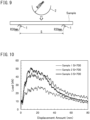
- the method of the three-point bending test used in the simulation is schematically shown in FIG. 9 .
- the three-point bending test was performed in such a way that a sample was placed on two fulcrums 1 and the sample was pressed from above by an impactor 2.
- the distance S between the two fulcrums 1 was 400 mm or 700 mm.
- the radius of curvature of the fulcrums 1 was 30 mm.
- the radius of curvature of the impactor 2 was 150 mm.
- the collision speed of the impactor 2 was 7.5 km/h.
- the width of the impactor 2 (length in a direction perpendicular to the page surface of FIG. 9 ) was larger than a total (120 mm) of widths of the top plate portion 112 and the reinforcing member 120 of Sample 3.
- FIGS. 10 to 13 Simulation results in a case in which the inter-fulcrum distance S was 700 mm are shown in FIGS. 10 to 13 . Note that a result of simulation of Sample 4 is shown only in FIG. 12 .
- the abscissa of FIG. 10 shows displacement amount.
- the displacement amount is a moved distance of the impactor 2 from when the impactor 2 collided with the sample.
- the ordinate of FIG. 10 shows load that occurred in the impactor 2.
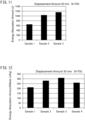
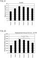
- FIG. 11 shows energy absorption amount of each sample at a time point when the displacement amount was 30 mm.
- FIG. 12 shows results of evaluation of energy absorption amount of each sample at a time point when the displacement amount was 30 mm in consideration of the mass of each sample.
- the ordinate of FIG. 12 shows values of the energy absorption amount of the ordinate of FIG. 11 divided by the mass of each sample.
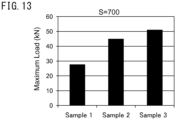
- FIG. 13 shows maximum values of load applied up to a time point when the displacement amount was 20 mm.
- Sample 3 of Inventive Example exhibited larger load and larger energy absorption amount in a region of an early stage of collision (region in which displacement amount was not more than about 30 mm) compared to Samples 1 and 2, which were Comparative Examples. Larger load and larger energy absorption amount mean higher resistance against collision. Further, the results of FIG. 12 show that even for the structural members with the same mass, the properties of Sample 3 of Inventive Example were higher than those of Samples 1, 2, and 4 which were Comparative Examples. For that reason, according to the present invention, it is possible to reduce the weight of the structural member while maintaining collision safety performance.
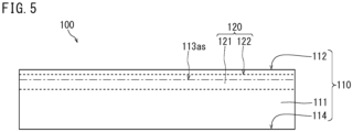
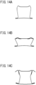
- FIGS. 14A to 14C show simulation results of cross-sectional shape of each sample when the displacement amount was 20 mm in a case in which the inter-fulcrum distance S was 700 mm.
- Sample 1 shown in FIG. 14A and Sample 2 shown in FIG. 14B the vertical wall portion falls outwardly.
- Sample 3 shown in FIG. 14C the vertical wall portion falls inwardly.
- the reinforcing member having an L-shaped cross section As a result of joining the reinforcing member having an L-shaped cross section in this way, the reinforcing member is deformed to be rotated in such a way to press the vertical wall portion inwardly when load is applied. That is, although a reinforcing member having an L-shaped cross section was joined to the ridge portion in this example, the shape of the reinforcing member may be any one provided that it can deform in such a way to make the vertical wall portion fall inwardly.
- FIGS. 15 to 18 show simulation results when the inter-fulcrum distance S was 400 mm.
- FIGS. 15 to 18 are figures corresponding to FIGS. 10 to 13 , respectively.
- FIG. 18 shows maximum values of load applied up to a time point when the displacement amount was 20 mm.
- Sample 3 of Inventive Example exhibited higher properties than Samples 1 and 2, which ware Comparative Examples.
- Example 2 simulation was performed by varying the width W2 of Sample 3.
- the width W2 of Sample 3 was varied from 20 mm (Sample 3) to 15 mm (Sample 3a), 10 mm (Sample 3b), and 5 mm (Sample 3c).
- Samples 3 and 3a to 3c are Inventive Examples. For those samples and Samples 1 and 2 of Comparative Example, similar evaluation as in Example 1 was performed. Samples 1 and 2 of Comparative Example were the same as Samples 1 and 2 described in Example 1.
- FIGS. 19 to 21 show simulation results when the inter-fulcrum distance S was 400 mm.
- FIGS. 19 to 21 are figures corresponding to FIGS. 11 to 13 , respectively. Note that, when the inter-fulcrum distance S was 400 mm, simulation results of Sample 4 are not shown.
- the samples of Inventive Example exhibited higher properties in the three-point bending test compared to samples of Comparative Example.
- the distance S was 400 mm
- the L-shape width was not less than 5 mm
- properties not less than those of Comparative Example were able to be obtained. Note that in any of samples of Inventive Example, the vertical wall portion was caused to fall inwardly by a collision of the impactor.
- FIGS. 22 to 24 show simulation results when the inter-fulcrum distance S was 700 mm.
- FIGS. 22 to 24 are figures corresponding to FIGS. 11 to 13 , respectively.
- sample of Inventive Example with an L-shape width of not less than 10 mm exhibited higher properties per unit mass compared to samples of Comparative Example.
- FIG. 24 the samples of Inventive Example with an L-shape width of not less than 10 mm exhibited a larger maximum value of load applied until a time point when the displacement amount was 20 mm compared to the samples of Comparative Example. Further, the samples of Inventive Example which had an L-shape width of not less than 15 mm exhibited higher properties in any test compared to Comparative Examples.
- the L-shape width is preferably not less than 5 mm, more preferably not less than 10 mm, and further preferably not less than 15 mm.
- the present invention can be utilized for structural members for automobiles.
Landscapes
- Engineering & Computer Science (AREA)
- Mechanical Engineering (AREA)
- Chemical & Material Sciences (AREA)
- Combustion & Propulsion (AREA)
- Transportation (AREA)
- Architecture (AREA)
- Civil Engineering (AREA)
- Structural Engineering (AREA)
- Body Structure For Vehicles (AREA)
Claims (11)
- Strukturelement (100) für ein Kraftfahrzeug, umfassend:ein pressgeformtes Produkt (110), das aus einem Stahlblech geformt ist; und ein Verstärkungselement (120), das an dem pressgeformten Produkt (110) befestigt ist, wobeidas pressgeformte Produkt (110) zwei vertikale Wandabschnitte (111) und einen oberen Plattenabschnitt (112) aufweist, der die beiden vertikalen Wandabschnitte (111) verbindet,das Verstärkungselement (120) ein Element ist, das einen L-förmigen Querschnitt aufweist und einen ersten plattenartigen Abschnitt (121) und einen zweiten plattenartigen Abschnitt (122) umfasst,der erste plattenartige Abschnitt (121) durch mindestens eine Art, die aus der Gruppe ausgewählt ist, die aus Schweißen, Verkleben, Hartlöten, Nieten und Reibrührfügen besteht, an einem der vertikalen Wandabschnitte (111) befestigt ist, so dass der zweite plattenartige Abschnitt (122) von einer Seite des vertikalen Wandabschnitts (111) entlang des oberen Plattenabschnitts (112) in Richtung nach außen vorspringt,ein Querschnitt eines Eckabschnitts (113) an einer Grenze zwischen dem vertikalen Wandabschnitt (111) und dem oberen Plattenabschnitt (112) eine abgerundete Form hat, undder zweite plattenartige Abschnitt (122) auf einer Seite des oberen Plattenabschnitts in Bezug auf eine Ausgangsposition (113a) der abgerundeten Form in dem vertikalen Wandabschnitt (111) so angeordnet ist, dass, wenn eine Last von der Seite des oberen Plattenabschnitts (112) aufgebracht wird, eine Verformung des Eckabschnitts (113) des pressgeformten Produkts (110) in Richtung nach außen durch einen Eckabschnitt (123) an einer Grenze zwischen dem ersten plattenartigen Abschnitt (121) und dem zweiten plattenartigen Abschnitt (122) des Verstärkungselements (120) unterdrückt wird, um die Wahrscheinlichkeit zu erhöhen, dass der vertikale Wandabschnitt (111) nach innen fällt.
- Strukturelement (100) für ein Kraftfahrzeug nach Anspruch 1, wobei
das Verstärkungselement (120) nur an dem pressgeformten Produkt (110) befestigt ist. - Strukturelement (100) für ein Kraftfahrzeug nach einem der Ansprüche 1 bis 2, wobei
wenn das Strukturelement (100) von der Seite des vertikalen Wandabschnitts (111) vorsteht, ein Vorsprungsbereich des Verstärkungselements (120) in einer Reichweite eines Vorsprungsbereichs des pressgeformten Produkts (110) liegt. - Strukturelement (100) für ein Kraftfahrzeug nach einem der Ansprüche 1 bis 3, wobei
das Verstärkungselement (120) aus Stahlblech hergestellt ist. - Strukturelement (100) für ein Kraftfahrzeug nach einem der Ansprüche 1 bis 4, ferner umfassendzwei der Verstärkungselemente (120), wobeidie Verstärkungselemente (120) jeweils an den beiden vertikalen Wandabschnitten (111) befestigt sind.
- Strukturelement (100) für ein Kraftfahrzeug nach einem der Ansprüche 1 bis 5, wobeidas pressgeformte Produkt (110) zwei Flanschabschnitte (114) aufweist, die sich jeweils von den Enden der beiden vertikalen Wandabschnitte (111) aus erstrecken,das Strukturelement (100) ferner ein zusätzliches Element (130) aus Stahlblech aufweist,das zusätzliche Element (130) an den beiden Flanschabschnitten (114) befestigt ist, so dass das pressgeformte Produkt (110) und das zusätzliche Element (130) einen geschlossenen Querschnitt bilden.
- Strukturelement (100) für ein Kraftfahrzeug nach einem der Ansprüche 1 bis 6, wobei
das Verstärkungselement (120) und das pressgeformte Produkt (110) die folgende Formel erfüllen:[Blechdicke (mm) des Verstärkungselements]×[Zugfestigkeit (MPa) des Verstärkungselements]×0.8≥[Blechdicke (mm) des pressgegformten Produkts]×[Zugfestigkeit (MPa)des pressgegformten Produkts] - Strukturelement (100) für ein Kraftfahrzeug nach einem der Ansprüche 1 bis 7, wobei
ein Abstand (D) zwischen dem oberen Plattenabschnitt (112) und dem zweiten plattenartigen Abschnitt (122) 0 mm bis 20 mm beträgt. - Strukturelement (100) für ein Kraftfahrzeug nach einem der Ansprüche 1 bis 8, wobei
ein Krümmungsradius eines Eckabschnitts (123) zwischen dem ersten plattenartigen Abschnitt (121) und dem zweiten plattenartigen Abschnitt (122) des Verstärkungselements (120) 5% bis 50% einer Gesamtlänge in einer Querschnittsansicht des Verstärkungselements (120) beträgt. - Strukturelement (100) für ein Kraftfahrzeug nach einem der Ansprüche 1 bis 9, wobei
wenn eine gesamte Länge in einer Längsrichtung des pressgeformten Produkts (110) mit L bezeichnet wird, das Verstärkungselement (120) in einem Bereich bis zu einem Abstand von L/6 zu beiden Seiten von einer Mitte des pressgeformten Produkts (110) in der Längsrichtung vorgesehen ist. - Strukturelement (100) für ein Kraftfahrzeug nach einem der Ansprüche 1 bis 10, wobei
ein Winkel (Z), der von dem ersten plattenartigen Abschnitt (121) und dem zweiten plattenartigen Abschnitt (122) gebildet wird, 70° bis 120° beträgt.
Applications Claiming Priority (2)
| Application Number | Priority Date | Filing Date | Title |
|---|---|---|---|
| JP2017077290 | 2017-04-10 | ||
| PCT/JP2018/014983 WO2018190312A1 (ja) | 2017-04-10 | 2018-04-10 | 自動車用の構造部材 |
Publications (4)
| Publication Number | Publication Date |
|---|---|
| EP3611058A1 EP3611058A1 (de) | 2020-02-19 |
| EP3611058A4 EP3611058A4 (de) | 2021-01-06 |
| EP3611058B1 EP3611058B1 (de) | 2024-09-04 |
| EP3611058B9 true EP3611058B9 (de) | 2024-11-20 |
Family
ID=63792890
Family Applications (1)
| Application Number | Title | Priority Date | Filing Date |
|---|---|---|---|
| EP18784350.3A Active EP3611058B9 (de) | 2017-04-10 | 2018-04-10 | Strukturelement für automobile |
Country Status (9)
| Country | Link |
|---|---|
| US (1) | US11400800B2 (de) |
| EP (1) | EP3611058B9 (de) |
| JP (1) | JP6485603B1 (de) |
| KR (1) | KR102295407B1 (de) |
| CN (1) | CN110494328B (de) |
| BR (1) | BR112019019574A2 (de) |
| CA (1) | CA3059156A1 (de) |
| MX (1) | MX2019012092A (de) |
| WO (1) | WO2018190312A1 (de) |
Families Citing this family (4)
| Publication number | Priority date | Publication date | Assignee | Title |
|---|---|---|---|---|
| FR3103759B1 (fr) * | 2019-11-28 | 2022-12-09 | Psa Automobiles Sa | Poutre de parechocs a renfort et vehicule equipee d’une telle poutre |
| WO2021172536A1 (ja) * | 2020-02-28 | 2021-09-02 | 日本製鉄株式会社 | パネル部品の補剛構造 |
| CN117460648A (zh) * | 2021-06-30 | 2024-01-26 | 住友重机械工业株式会社 | 加固单元及加固部件 |
| JP7792326B2 (ja) * | 2022-12-02 | 2025-12-25 | 本田技研工業株式会社 | 板材の接合構造及び製造方法 |
Family Cites Families (68)
| Publication number | Priority date | Publication date | Assignee | Title |
|---|---|---|---|---|
| US1071565A (en) * | 1912-11-11 | 1913-08-26 | Carl Gustav Morgner | Screen for passenger-cars. |
| US1433232A (en) * | 1920-11-17 | 1922-10-24 | Rogers Richard Hawke | Beam or like structural member for use in reenforced concrete construction and other purposes |
| US3324616A (en) * | 1965-05-19 | 1967-06-13 | Armco Steel Corp | All-steel nailable car flooring |
| US3373534A (en) * | 1966-02-01 | 1968-03-19 | American Metal Climax Inc | Attachment clip for metal shingles |
| IT942895B (it) * | 1971-11-19 | 1973-04-02 | Fiat Spa | Perfezionamenti nelle carrozzerie di autoveicoli |
| US3834105A (en) * | 1972-12-15 | 1974-09-10 | Kaiser Steel Corp | Nailable steel floor planking for freight vehicles |
| JPS52126517U (de) * | 1976-03-22 | 1977-09-26 | ||
| JPS614727Y2 (de) * | 1980-07-16 | 1986-02-14 | ||
| US4424652A (en) * | 1980-10-31 | 1984-01-10 | Turner Arthur R | Pre-cambered steel beam |
| US4514008A (en) * | 1981-06-05 | 1985-04-30 | Toyota Jidosha Kogyo Kabushiki Kaisha | Vehicle body floor construction of motor vehicle |
| US4441294A (en) * | 1982-06-07 | 1984-04-10 | Riley Robert E | Support for roof insulation in metal buildings and method for insulating the roof of such buildings |
| US4512835A (en) * | 1983-06-06 | 1985-04-23 | Hercules Incorporated | Method of making a curved composite beam |
| US5056861A (en) * | 1990-04-23 | 1991-10-15 | Austria Metall Aktiengesellschaft | Impact girder for the side of an automotive vehicle |
| JPH053402U (ja) * | 1991-06-27 | 1993-01-19 | 新日本製鐵株式会社 | 座屈拘束筋かい部材 |
| DE4127729C2 (de) * | 1991-08-22 | 1994-08-11 | Ford Werke Ag | Hohlträger für eine Kraftfahrzeugkarosserie an der Befestigungsstelle eines Aggregates |
| JPH07257425A (ja) * | 1994-03-18 | 1995-10-09 | Honda Motor Co Ltd | 自動車用車体のサブフレーム取付け構造 |
| DE4429104A1 (de) * | 1994-08-17 | 1996-02-22 | Pirchl Gerhard | Verfahren zur Herstellung eines Hitzeschildes und Hitzeschild, welches nach dem Verfahren hergestellt ist |
| US6179355B1 (en) * | 1998-12-18 | 2001-01-30 | Ford Global Technologies, Inc. | Automotive vehicle bumper assembly |
| US6360510B1 (en) * | 1998-12-22 | 2002-03-26 | Porta-Fab Corporation | Hat-channel stud for modular building system |
| JP3801805B2 (ja) * | 1999-03-16 | 2006-07-26 | 本田技研工業株式会社 | 閉断面湾曲長尺材 |
| JP2001001053A (ja) * | 1999-04-22 | 2001-01-09 | Aisin Seiki Co Ltd | ロール成形品および自動車用バンパー |
| WO2001079086A1 (en) * | 2000-04-13 | 2001-10-25 | Yamakyu Chain Co., Ltd. | Frame material of conveyor system, running frame device using the frame material, and running rail mounting structure of conveyor system |
| US6389697B1 (en) * | 2000-07-17 | 2002-05-21 | Fuel Cell Components And Integrators, Inc. | Fabricating automotive spaceframes using electromagnetic forming or magnetic pulse welding |
| WO2003046230A1 (fr) * | 2001-11-27 | 2003-06-05 | Kikuchi Co., Ltd. | Moulage a la presse, procede de trempe haute frequence associe et systeme de trempe haute frequence associe |
| JP2004155219A (ja) * | 2002-11-01 | 2004-06-03 | Fuji Heavy Ind Ltd | 自動車の車体後部構造 |
| DE10301445B4 (de) * | 2003-01-16 | 2005-11-17 | Airbus Deutschland Gmbh | Leichtbau-Strukturbauteil insbesondere für Flugzeuge und Verfahren zu seiner Herstellung |
| ZA200510240B (en) * | 2003-06-23 | 2007-03-28 | Smorgon Steel Litesteel Prod | An improved beam |
| US7017319B2 (en) * | 2003-09-12 | 2006-03-28 | Kenneth Peter Bowman | Method and system for finishing openings for windows and other framed inserts |
| US8407966B2 (en) * | 2003-10-28 | 2013-04-02 | Ispan Systems Lp | Cold-formed steel joist |
| US7243983B2 (en) * | 2005-02-23 | 2007-07-17 | Asc Incorporated | Retractable pillar for convertible vehicle |
| BRPI0609143A2 (pt) * | 2005-03-17 | 2011-09-13 | Ind Origami Llc | folha de material para a formação de uma estrutura estrutural tridimensional, viga oca e armação de exoesqueleto |
| SE527968C2 (sv) * | 2005-05-25 | 2006-07-25 | Gestamp Hardtech Ab | Stötfångarbalk för fordon |
| JP5221861B2 (ja) * | 2006-09-14 | 2013-06-26 | 新日鐵住金株式会社 | 車両用構造部材 |
| ATE504485T1 (de) * | 2007-06-18 | 2011-04-15 | Honda Motor Co Ltd | Struktur für ein seitenteil eines fahrzeugkörpers |
| DE102007033868B4 (de) * | 2007-07-20 | 2013-01-31 | Airbus Operations Gmbh | Profil mit wenigstens einem Hohlprofilquerschnitt |
| DE202007016333U1 (de) * | 2007-09-20 | 2008-03-06 | Bos Gmbh & Co. Kg | Kassette zur Aufnahme einer Wickelwelle |
| US8176696B2 (en) * | 2007-10-24 | 2012-05-15 | Leblang Dennis William | Building construction for forming columns and beams within a wall mold |
| US8176706B2 (en) * | 2008-08-21 | 2012-05-15 | Mitek Holdings, Inc. | Column assembly for a building framework |
| JP5573233B2 (ja) | 2010-03-03 | 2014-08-20 | マツダ株式会社 | 車両用フレーム構造 |
| JP2011067841A (ja) | 2009-09-25 | 2011-04-07 | Daihatsu Motor Co Ltd | 中空柱状部品の製造方法 |
| CA2779192C (en) * | 2009-11-05 | 2013-07-02 | Honda Motor Co., Ltd. | Vehicle body structure |
| NZ582003A (en) * | 2009-12-14 | 2011-02-25 | Illinois Tool Works | Truss and cementitious building element connected via connector ingtegral with element and accessible to connect to truss |
| JP5427895B2 (ja) * | 2009-12-22 | 2014-02-26 | 本田技研工業株式会社 | 車体側部構造 |
| WO2011088554A1 (en) * | 2010-01-20 | 2011-07-28 | Magna International Inc. | Bi-metallic component and method of making the same |
| JP5533128B2 (ja) | 2010-03-29 | 2014-06-25 | Jfeスチール株式会社 | 自動車の衝突エネルギー吸収部材の補強構造 |
| FR2958628A1 (fr) * | 2010-04-13 | 2011-10-14 | Monnier Jacques Le | Systeme de pliage et de verrouillage auto-bloquants, permettant de concevoir des bacs ou des couvercles. |
| US8307610B2 (en) * | 2010-05-25 | 2012-11-13 | Landers Leroy A | Insulative metallic channel and construction assembly |
| CN103228392B (zh) | 2010-09-16 | 2016-02-17 | 新日铁住金株式会社 | 成形构件及其制造方法 |
| JP5739242B2 (ja) * | 2011-06-07 | 2015-06-24 | 株式会社エフテック | ビーム部材 |
| JP5862214B2 (ja) | 2011-11-10 | 2016-02-16 | スズキ株式会社 | 車両用シートの取付構造 |
| US8857133B2 (en) * | 2011-11-28 | 2014-10-14 | John Powers, III | Purlin construction for roof structures |
| US9027309B2 (en) * | 2012-01-09 | 2015-05-12 | Consolidated Metal Products, Inc. | Welded hot-rolled high-strength steel structural members and methods |
| JP2013189173A (ja) | 2012-03-15 | 2013-09-26 | Nippon Steel & Sumitomo Metal Corp | 自動車車体用構造部材およびその製造方法 |
| JP5926089B2 (ja) * | 2012-03-29 | 2016-05-25 | 東プレ株式会社 | プレス成形品 |
| CA2907413C (en) | 2013-04-04 | 2017-06-13 | Nippon Steel & Sumitomo Metal Corporation | Automobile structural member and manufacturing method of the same |
| US9057190B1 (en) * | 2013-08-22 | 2015-06-16 | Roger Winter | Deck system and components thereof, and methods of assembling and disassembling deck systems and components |
| MX2016006940A (es) * | 2013-11-28 | 2016-09-27 | Nippon Steel & Sumitomo Metal Corp | Placa de acero en blanco, metodo de produccion y dispositivo de produccion de la misma y metodo de produccion de un producto formado por prensado usando una placa de acero en blanco. |
| US9884597B2 (en) * | 2014-04-28 | 2018-02-06 | Shape Corp. | Multi-strip beam-forming apparatus, method, and beam |
| US9381880B2 (en) * | 2014-04-28 | 2016-07-05 | Shape Corp. | Multi-strip beam-forming apparatus, method and beam |
| HUE042774T2 (hu) * | 2014-09-22 | 2019-07-29 | Arcelormittal | Eljárás jármû ajtókeret háromdimenziós belsõ megerõsítõ elem gyártására, jármû ajtókeret gyártására és jármû megerõsítõ szerkezet gyártására |
| US10507873B2 (en) * | 2015-03-24 | 2019-12-17 | Teijin Limited | Resin structure and vehicle component |
| JP2017001521A (ja) | 2015-06-10 | 2017-01-05 | トヨタ自動車株式会社 | 車両側部構造 |
| JP2017007450A (ja) * | 2015-06-19 | 2017-01-12 | 豊田鉄工株式会社 | バンパリインフォースメント構造 |
| US10486750B2 (en) * | 2015-08-20 | 2019-11-26 | Nippon Steel Corporation | Steel sheet member combination structure, automotive structural member, center pillar, bumper, and door beam |
| DE102015114105B4 (de) * | 2015-08-25 | 2018-11-29 | Benteler Automobiltechnik Gmbh | Aufprallträger für ein Kraftfahrzeug sowie Verfahren zu seiner Herstellung |
| JP6479612B2 (ja) * | 2015-09-03 | 2019-03-06 | 豊田鉄工株式会社 | バンパリインフォースメントの製造法 |
| DE102015218454A1 (de) | 2015-09-25 | 2017-03-30 | Bayerische Motoren Werke Aktiengesellschaft | Pressgehärtetes Blechbauteil mit wenigstens einer Sollbruchstelle, sowie Bauteilverbund und Kraftfahrzeugkarosserie mit solchem Blechbauteil |
| EP3434501A4 (de) * | 2016-03-23 | 2019-11-27 | Nippon Steel Corporation | Türinnenverkleidung und verfahren zur herstellung einer türinnenverkleidung |
-
2018
- 2018-04-10 EP EP18784350.3A patent/EP3611058B9/de active Active
- 2018-04-10 WO PCT/JP2018/014983 patent/WO2018190312A1/ja not_active Ceased
- 2018-04-10 BR BR112019019574A patent/BR112019019574A2/pt not_active IP Right Cessation
- 2018-04-10 CN CN201880023326.2A patent/CN110494328B/zh active Active
- 2018-04-10 MX MX2019012092A patent/MX2019012092A/es unknown
- 2018-04-10 KR KR1020197032897A patent/KR102295407B1/ko active Active
- 2018-04-10 JP JP2018546719A patent/JP6485603B1/ja active Active
- 2018-04-10 US US16/494,915 patent/US11400800B2/en active Active
- 2018-04-10 CA CA3059156A patent/CA3059156A1/en not_active Abandoned
Also Published As
| Publication number | Publication date |
|---|---|
| CA3059156A1 (en) | 2018-10-18 |
| EP3611058A1 (de) | 2020-02-19 |
| CN110494328A (zh) | 2019-11-22 |
| MX2019012092A (es) | 2019-11-21 |
| WO2018190312A1 (ja) | 2018-10-18 |
| US11400800B2 (en) | 2022-08-02 |
| KR102295407B1 (ko) | 2021-08-30 |
| BR112019019574A2 (pt) | 2020-04-14 |
| JPWO2018190312A1 (ja) | 2019-04-18 |
| US20200031208A1 (en) | 2020-01-30 |
| EP3611058A4 (de) | 2021-01-06 |
| EP3611058B1 (de) | 2024-09-04 |
| KR20190133253A (ko) | 2019-12-02 |
| CN110494328B (zh) | 2023-07-04 |
| JP6485603B1 (ja) | 2019-03-20 |
Similar Documents
| Publication | Publication Date | Title |
|---|---|---|
| EP2823928B1 (de) | Kopplungsstruktur | |
| EP3611058B1 (de) | Strukturelement für automobile | |
| KR102202275B1 (ko) | 언더런 프로텍터의 지지 구조 | |
| KR102558628B1 (ko) | 차량용 구조 부재 | |
| WO2009098939A1 (ja) | 車両用フード構造 | |
| JP5203870B2 (ja) | 曲げ圧壊特性に優れた自動車車体補強材 | |
| JP2010042753A (ja) | バンパーリインフォースメントおよびその製造方法 | |
| JP6304379B2 (ja) | ドアインパクトビーム | |
| CN110228534A (zh) | 车辆中柱 | |
| JP5106073B2 (ja) | 自動車用バンパー補強材 | |
| JP4289130B2 (ja) | フロントピラー補強構造 | |
| EP3932750B1 (de) | Strukturelement für ein fahrzeug | |
| EP3932749A1 (de) | Fahrzeugfrontkarosseriestruktur und fahrzeug | |
| CN115803232A (zh) | 车辆用构造部件 | |
| JP7567967B1 (ja) | 自動車のサブフレーム構造 | |
| JP2009220635A (ja) | 自動車用補強部材 | |
| JP2003112656A (ja) | 車両のルーフ構造 | |
| JP7192837B2 (ja) | 車両用構造部材 | |
| JP2025147774A (ja) | 車体構造 | |
| CN120897866A (zh) | 汽车的副车架结构 |
Legal Events
| Date | Code | Title | Description |
|---|---|---|---|
| STAA | Information on the status of an ep patent application or granted ep patent |
Free format text: STATUS: THE INTERNATIONAL PUBLICATION HAS BEEN MADE |
|
| PUAI | Public reference made under article 153(3) epc to a published international application that has entered the european phase |
Free format text: ORIGINAL CODE: 0009012 |
|
| STAA | Information on the status of an ep patent application or granted ep patent |
Free format text: STATUS: REQUEST FOR EXAMINATION WAS MADE |
|
| 17P | Request for examination filed |
Effective date: 20191031 |
|
| AK | Designated contracting states |
Kind code of ref document: A1 Designated state(s): AL AT BE BG CH CY CZ DE DK EE ES FI FR GB GR HR HU IE IS IT LI LT LU LV MC MK MT NL NO PL PT RO RS SE SI SK SM TR |
|
| AX | Request for extension of the european patent |
Extension state: BA ME |
|
| DAV | Request for validation of the european patent (deleted) | ||
| DAX | Request for extension of the european patent (deleted) | ||
| A4 | Supplementary search report drawn up and despatched |
Effective date: 20201209 |
|
| RIC1 | Information provided on ipc code assigned before grant |
Ipc: B62D 25/00 20060101ALI20201203BHEP Ipc: B62D 21/00 20060101AFI20201203BHEP Ipc: B62D 25/04 20060101ALN20201203BHEP Ipc: B62D 25/02 20060101ALN20201203BHEP |
|
| STAA | Information on the status of an ep patent application or granted ep patent |
Free format text: STATUS: EXAMINATION IS IN PROGRESS |
|
| 17Q | First examination report despatched |
Effective date: 20220808 |
|
| REG | Reference to a national code |
Free format text: PREVIOUS MAIN CLASS: B60R0019040000 Ipc: B62D0021000000 Ref country code: DE Ref legal event code: R079 Ref document number: 602018073999 Country of ref document: DE Free format text: PREVIOUS MAIN CLASS: B60R0019040000 Ipc: B62D0021000000 |
|
| GRAP | Despatch of communication of intention to grant a patent |
Free format text: ORIGINAL CODE: EPIDOSNIGR1 |
|
| STAA | Information on the status of an ep patent application or granted ep patent |
Free format text: STATUS: GRANT OF PATENT IS INTENDED |
|
| RIC1 | Information provided on ipc code assigned before grant |
Ipc: B62D 25/04 20060101ALN20240314BHEP Ipc: B62D 25/02 20060101ALN20240314BHEP Ipc: B62D 25/00 20060101ALI20240314BHEP Ipc: B62D 21/00 20060101AFI20240314BHEP |
|
| INTG | Intention to grant announced |
Effective date: 20240404 |
|
| GRAS | Grant fee paid |
Free format text: ORIGINAL CODE: EPIDOSNIGR3 |
|
| GRAA | (expected) grant |
Free format text: ORIGINAL CODE: 0009210 |
|
| STAA | Information on the status of an ep patent application or granted ep patent |
Free format text: STATUS: THE PATENT HAS BEEN GRANTED |
|
| AK | Designated contracting states |
Kind code of ref document: B1 Designated state(s): AL AT BE BG CH CY CZ DE DK EE ES FI FR GB GR HR HU IE IS IT LI LT LU LV MC MK MT NL NO PL PT RO RS SE SI SK SM TR |
|
| REG | Reference to a national code |
Ref country code: GB Ref legal event code: FG4D |
|
| REG | Reference to a national code |
Ref country code: CH Ref legal event code: EP |
|
| REG | Reference to a national code |
Ref country code: IE Ref legal event code: FG4D |
|
| REG | Reference to a national code |
Ref country code: DE Ref legal event code: R096 Ref document number: 602018073999 Country of ref document: DE |
|
| REG | Reference to a national code |
Ref country code: CH Ref legal event code: PK Free format text: BERICHTIGUNG B9 |
|
| REG | Reference to a national code |
Ref country code: LT Ref legal event code: MG9D |
|
| REG | Reference to a national code |
Ref country code: NL Ref legal event code: MP Effective date: 20240904 |
|
| PG25 | Lapsed in a contracting state [announced via postgrant information from national office to epo] |
Ref country code: NO Free format text: LAPSE BECAUSE OF FAILURE TO SUBMIT A TRANSLATION OF THE DESCRIPTION OR TO PAY THE FEE WITHIN THE PRESCRIBED TIME-LIMIT Effective date: 20241204 |
|
| PG25 | Lapsed in a contracting state [announced via postgrant information from national office to epo] |
Ref country code: GR Free format text: LAPSE BECAUSE OF FAILURE TO SUBMIT A TRANSLATION OF THE DESCRIPTION OR TO PAY THE FEE WITHIN THE PRESCRIBED TIME-LIMIT Effective date: 20241205 Ref country code: FI Free format text: LAPSE BECAUSE OF FAILURE TO SUBMIT A TRANSLATION OF THE DESCRIPTION OR TO PAY THE FEE WITHIN THE PRESCRIBED TIME-LIMIT Effective date: 20240904 Ref country code: PL Free format text: LAPSE BECAUSE OF FAILURE TO SUBMIT A TRANSLATION OF THE DESCRIPTION OR TO PAY THE FEE WITHIN THE PRESCRIBED TIME-LIMIT Effective date: 20240904 |
|
| PG25 | Lapsed in a contracting state [announced via postgrant information from national office to epo] |
Ref country code: BG Free format text: LAPSE BECAUSE OF FAILURE TO SUBMIT A TRANSLATION OF THE DESCRIPTION OR TO PAY THE FEE WITHIN THE PRESCRIBED TIME-LIMIT Effective date: 20240904 |
|
| PG25 | Lapsed in a contracting state [announced via postgrant information from national office to epo] |
Ref country code: LV Free format text: LAPSE BECAUSE OF FAILURE TO SUBMIT A TRANSLATION OF THE DESCRIPTION OR TO PAY THE FEE WITHIN THE PRESCRIBED TIME-LIMIT Effective date: 20240904 |
|
| PG25 | Lapsed in a contracting state [announced via postgrant information from national office to epo] |
Ref country code: HR Free format text: LAPSE BECAUSE OF FAILURE TO SUBMIT A TRANSLATION OF THE DESCRIPTION OR TO PAY THE FEE WITHIN THE PRESCRIBED TIME-LIMIT Effective date: 20240904 |
|
| PG25 | Lapsed in a contracting state [announced via postgrant information from national office to epo] |
Ref country code: ES Free format text: LAPSE BECAUSE OF FAILURE TO SUBMIT A TRANSLATION OF THE DESCRIPTION OR TO PAY THE FEE WITHIN THE PRESCRIBED TIME-LIMIT Effective date: 20240904 Ref country code: RS Free format text: LAPSE BECAUSE OF FAILURE TO SUBMIT A TRANSLATION OF THE DESCRIPTION OR TO PAY THE FEE WITHIN THE PRESCRIBED TIME-LIMIT Effective date: 20241204 |
|
| PG25 | Lapsed in a contracting state [announced via postgrant information from national office to epo] |
Ref country code: RS Free format text: LAPSE BECAUSE OF FAILURE TO SUBMIT A TRANSLATION OF THE DESCRIPTION OR TO PAY THE FEE WITHIN THE PRESCRIBED TIME-LIMIT Effective date: 20241204 Ref country code: PL Free format text: LAPSE BECAUSE OF FAILURE TO SUBMIT A TRANSLATION OF THE DESCRIPTION OR TO PAY THE FEE WITHIN THE PRESCRIBED TIME-LIMIT Effective date: 20240904 Ref country code: NO Free format text: LAPSE BECAUSE OF FAILURE TO SUBMIT A TRANSLATION OF THE DESCRIPTION OR TO PAY THE FEE WITHIN THE PRESCRIBED TIME-LIMIT Effective date: 20241204 Ref country code: LV Free format text: LAPSE BECAUSE OF FAILURE TO SUBMIT A TRANSLATION OF THE DESCRIPTION OR TO PAY THE FEE WITHIN THE PRESCRIBED TIME-LIMIT Effective date: 20240904 Ref country code: HR Free format text: LAPSE BECAUSE OF FAILURE TO SUBMIT A TRANSLATION OF THE DESCRIPTION OR TO PAY THE FEE WITHIN THE PRESCRIBED TIME-LIMIT Effective date: 20240904 Ref country code: GR Free format text: LAPSE BECAUSE OF FAILURE TO SUBMIT A TRANSLATION OF THE DESCRIPTION OR TO PAY THE FEE WITHIN THE PRESCRIBED TIME-LIMIT Effective date: 20241205 Ref country code: FI Free format text: LAPSE BECAUSE OF FAILURE TO SUBMIT A TRANSLATION OF THE DESCRIPTION OR TO PAY THE FEE WITHIN THE PRESCRIBED TIME-LIMIT Effective date: 20240904 Ref country code: ES Free format text: LAPSE BECAUSE OF FAILURE TO SUBMIT A TRANSLATION OF THE DESCRIPTION OR TO PAY THE FEE WITHIN THE PRESCRIBED TIME-LIMIT Effective date: 20240904 Ref country code: BG Free format text: LAPSE BECAUSE OF FAILURE TO SUBMIT A TRANSLATION OF THE DESCRIPTION OR TO PAY THE FEE WITHIN THE PRESCRIBED TIME-LIMIT Effective date: 20240904 |
|
| REG | Reference to a national code |
Ref country code: AT Ref legal event code: MK05 Ref document number: 1720108 Country of ref document: AT Kind code of ref document: T Effective date: 20240904 |
|
| PG25 | Lapsed in a contracting state [announced via postgrant information from national office to epo] |
Ref country code: NL Free format text: LAPSE BECAUSE OF FAILURE TO SUBMIT A TRANSLATION OF THE DESCRIPTION OR TO PAY THE FEE WITHIN THE PRESCRIBED TIME-LIMIT Effective date: 20240904 |
|
| PG25 | Lapsed in a contracting state [announced via postgrant information from national office to epo] |
Ref country code: IS Free format text: LAPSE BECAUSE OF FAILURE TO SUBMIT A TRANSLATION OF THE DESCRIPTION OR TO PAY THE FEE WITHIN THE PRESCRIBED TIME-LIMIT Effective date: 20250104 Ref country code: PT Free format text: LAPSE BECAUSE OF FAILURE TO SUBMIT A TRANSLATION OF THE DESCRIPTION OR TO PAY THE FEE WITHIN THE PRESCRIBED TIME-LIMIT Effective date: 20250106 |
|
| PG25 | Lapsed in a contracting state [announced via postgrant information from national office to epo] |
Ref country code: SM Free format text: LAPSE BECAUSE OF FAILURE TO SUBMIT A TRANSLATION OF THE DESCRIPTION OR TO PAY THE FEE WITHIN THE PRESCRIBED TIME-LIMIT Effective date: 20240904 Ref country code: RO Free format text: LAPSE BECAUSE OF FAILURE TO SUBMIT A TRANSLATION OF THE DESCRIPTION OR TO PAY THE FEE WITHIN THE PRESCRIBED TIME-LIMIT Effective date: 20240904 |
|
| PG25 | Lapsed in a contracting state [announced via postgrant information from national office to epo] |
Ref country code: EE Free format text: LAPSE BECAUSE OF FAILURE TO SUBMIT A TRANSLATION OF THE DESCRIPTION OR TO PAY THE FEE WITHIN THE PRESCRIBED TIME-LIMIT Effective date: 20240904 Ref country code: AT Free format text: LAPSE BECAUSE OF FAILURE TO SUBMIT A TRANSLATION OF THE DESCRIPTION OR TO PAY THE FEE WITHIN THE PRESCRIBED TIME-LIMIT Effective date: 20240904 |
|
| PG25 | Lapsed in a contracting state [announced via postgrant information from national office to epo] |
Ref country code: CZ Free format text: LAPSE BECAUSE OF FAILURE TO SUBMIT A TRANSLATION OF THE DESCRIPTION OR TO PAY THE FEE WITHIN THE PRESCRIBED TIME-LIMIT Effective date: 20240904 |
|
| PG25 | Lapsed in a contracting state [announced via postgrant information from national office to epo] |
Ref country code: SK Free format text: LAPSE BECAUSE OF FAILURE TO SUBMIT A TRANSLATION OF THE DESCRIPTION OR TO PAY THE FEE WITHIN THE PRESCRIBED TIME-LIMIT Effective date: 20240904 Ref country code: IT Free format text: LAPSE BECAUSE OF FAILURE TO SUBMIT A TRANSLATION OF THE DESCRIPTION OR TO PAY THE FEE WITHIN THE PRESCRIBED TIME-LIMIT Effective date: 20240904 |
|
| REG | Reference to a national code |
Ref country code: DE Ref legal event code: R097 Ref document number: 602018073999 Country of ref document: DE |
|
| PGFP | Annual fee paid to national office [announced via postgrant information from national office to epo] |
Ref country code: DE Payment date: 20250415 Year of fee payment: 8 |
|
| PG25 | Lapsed in a contracting state [announced via postgrant information from national office to epo] |
Ref country code: DK Free format text: LAPSE BECAUSE OF FAILURE TO SUBMIT A TRANSLATION OF THE DESCRIPTION OR TO PAY THE FEE WITHIN THE PRESCRIBED TIME-LIMIT Effective date: 20240904 |
|
| PLBE | No opposition filed within time limit |
Free format text: ORIGINAL CODE: 0009261 |
|
| STAA | Information on the status of an ep patent application or granted ep patent |
Free format text: STATUS: NO OPPOSITION FILED WITHIN TIME LIMIT |
|
| PGFP | Annual fee paid to national office [announced via postgrant information from national office to epo] |
Ref country code: FR Payment date: 20250425 Year of fee payment: 8 |
|
| 26N | No opposition filed |
Effective date: 20250605 |
|
| PG25 | Lapsed in a contracting state [announced via postgrant information from national office to epo] |
Ref country code: SE Free format text: LAPSE BECAUSE OF FAILURE TO SUBMIT A TRANSLATION OF THE DESCRIPTION OR TO PAY THE FEE WITHIN THE PRESCRIBED TIME-LIMIT Effective date: 20240904 |
|
| REG | Reference to a national code |
Ref country code: CH Ref legal event code: H13 Free format text: ST27 STATUS EVENT CODE: U-0-0-H10-H13 (AS PROVIDED BY THE NATIONAL OFFICE) Effective date: 20251125 |
|
| PG25 | Lapsed in a contracting state [announced via postgrant information from national office to epo] |
Ref country code: LU Free format text: LAPSE BECAUSE OF NON-PAYMENT OF DUE FEES Effective date: 20250410 |
|
| PG25 | Lapsed in a contracting state [announced via postgrant information from national office to epo] |
Ref country code: MC Free format text: LAPSE BECAUSE OF FAILURE TO SUBMIT A TRANSLATION OF THE DESCRIPTION OR TO PAY THE FEE WITHIN THE PRESCRIBED TIME-LIMIT Effective date: 20240904 |
|
| GBPC | Gb: european patent ceased through non-payment of renewal fee |
Effective date: 20250410 |
|
| REG | Reference to a national code |
Ref country code: BE Ref legal event code: MM Effective date: 20250430 |
|
| PG25 | Lapsed in a contracting state [announced via postgrant information from national office to epo] |
Ref country code: GB Free format text: LAPSE BECAUSE OF NON-PAYMENT OF DUE FEES Effective date: 20250410 |
|
| PG25 | Lapsed in a contracting state [announced via postgrant information from national office to epo] |
Ref country code: BE Free format text: LAPSE BECAUSE OF NON-PAYMENT OF DUE FEES Effective date: 20250430 |
|
| PG25 | Lapsed in a contracting state [announced via postgrant information from national office to epo] |
Ref country code: CH Free format text: LAPSE BECAUSE OF NON-PAYMENT OF DUE FEES Effective date: 20250430 |