EP3608154B1 - Aufhängungsrahmen für magnetschwebefahrzeug - Google Patents
Aufhängungsrahmen für magnetschwebefahrzeug Download PDFInfo
- Publication number
- EP3608154B1 EP3608154B1 EP18840954.4A EP18840954A EP3608154B1 EP 3608154 B1 EP3608154 B1 EP 3608154B1 EP 18840954 A EP18840954 A EP 18840954A EP 3608154 B1 EP3608154 B1 EP 3608154B1
- Authority
- EP
- European Patent Office
- Prior art keywords
- suspension
- longitudinal beam
- frame assembly
- pull rod
- suspension frame
- Prior art date
- Legal status (The legal status is an assumption and is not a legal conclusion. Google has not performed a legal analysis and makes no representation as to the accuracy of the status listed.)
- Active
Links
Images


Classifications
-
- B—PERFORMING OPERATIONS; TRANSPORTING
- B60—VEHICLES IN GENERAL
- B60L—PROPULSION OF ELECTRICALLY-PROPELLED VEHICLES; SUPPLYING ELECTRIC POWER FOR AUXILIARY EQUIPMENT OF ELECTRICALLY-PROPELLED VEHICLES; ELECTRODYNAMIC BRAKE SYSTEMS FOR VEHICLES IN GENERAL; MAGNETIC SUSPENSION OR LEVITATION FOR VEHICLES; MONITORING OPERATING VARIABLES OF ELECTRICALLY-PROPELLED VEHICLES; ELECTRIC SAFETY DEVICES FOR ELECTRICALLY-PROPELLED VEHICLES
- B60L13/00—Electric propulsion for monorail vehicles, suspension vehicles or rack railways; Magnetic suspension or levitation for vehicles
- B60L13/04—Magnetic suspension or levitation for vehicles
-
- B—PERFORMING OPERATIONS; TRANSPORTING
- B61—RAILWAYS
- B61B—RAILWAY SYSTEMS; EQUIPMENT THEREFOR NOT OTHERWISE PROVIDED FOR
- B61B13/00—Other railway systems
- B61B13/08—Sliding or levitation systems
-
- B—PERFORMING OPERATIONS; TRANSPORTING
- B61—RAILWAYS
- B61F—RAIL VEHICLE SUSPENSIONS, e.g. UNDERFRAMES, BOGIES OR ARRANGEMENTS OF WHEEL AXLES; RAIL VEHICLES FOR USE ON TRACKS OF DIFFERENT WIDTH; PREVENTING DERAILING OF RAIL VEHICLES; WHEEL GUARDS, OBSTRUCTION REMOVERS OR THE LIKE FOR RAIL VEHICLES
- B61F5/00—Constructional details of bogies; Connections between bogies and vehicle underframes; Arrangements or devices for adjusting or allowing self-adjustment of wheel axles or bogies when rounding curves
- B61F5/50—Other details
- B61F5/52—Bogie frames
-
- B—PERFORMING OPERATIONS; TRANSPORTING
- B60—VEHICLES IN GENERAL
- B60L—PROPULSION OF ELECTRICALLY-PROPELLED VEHICLES; SUPPLYING ELECTRIC POWER FOR AUXILIARY EQUIPMENT OF ELECTRICALLY-PROPELLED VEHICLES; ELECTRODYNAMIC BRAKE SYSTEMS FOR VEHICLES IN GENERAL; MAGNETIC SUSPENSION OR LEVITATION FOR VEHICLES; MONITORING OPERATING VARIABLES OF ELECTRICALLY-PROPELLED VEHICLES; ELECTRIC SAFETY DEVICES FOR ELECTRICALLY-PROPELLED VEHICLES
- B60L13/00—Electric propulsion for monorail vehicles, suspension vehicles or rack railways; Magnetic suspension or levitation for vehicles
- B60L13/03—Electric propulsion by linear motors
-
- B—PERFORMING OPERATIONS; TRANSPORTING
- B60—VEHICLES IN GENERAL
- B60L—PROPULSION OF ELECTRICALLY-PROPELLED VEHICLES; SUPPLYING ELECTRIC POWER FOR AUXILIARY EQUIPMENT OF ELECTRICALLY-PROPELLED VEHICLES; ELECTRODYNAMIC BRAKE SYSTEMS FOR VEHICLES IN GENERAL; MAGNETIC SUSPENSION OR LEVITATION FOR VEHICLES; MONITORING OPERATING VARIABLES OF ELECTRICALLY-PROPELLED VEHICLES; ELECTRIC SAFETY DEVICES FOR ELECTRICALLY-PROPELLED VEHICLES
- B60L13/00—Electric propulsion for monorail vehicles, suspension vehicles or rack railways; Magnetic suspension or levitation for vehicles
- B60L13/10—Combination of electric propulsion and magnetic suspension or levitation
-
- B—PERFORMING OPERATIONS; TRANSPORTING
- B60—VEHICLES IN GENERAL
- B60L—PROPULSION OF ELECTRICALLY-PROPELLED VEHICLES; SUPPLYING ELECTRIC POWER FOR AUXILIARY EQUIPMENT OF ELECTRICALLY-PROPELLED VEHICLES; ELECTRODYNAMIC BRAKE SYSTEMS FOR VEHICLES IN GENERAL; MAGNETIC SUSPENSION OR LEVITATION FOR VEHICLES; MONITORING OPERATING VARIABLES OF ELECTRICALLY-PROPELLED VEHICLES; ELECTRIC SAFETY DEVICES FOR ELECTRICALLY-PROPELLED VEHICLES
- B60L2200/00—Type of vehicles
- B60L2200/26—Rail vehicles
-
- F—MECHANICAL ENGINEERING; LIGHTING; HEATING; WEAPONS; BLASTING
- F16—ENGINEERING ELEMENTS AND UNITS; GENERAL MEASURES FOR PRODUCING AND MAINTAINING EFFECTIVE FUNCTIONING OF MACHINES OR INSTALLATIONS; THERMAL INSULATION IN GENERAL
- F16C—SHAFTS; FLEXIBLE SHAFTS; ELEMENTS OR CRANKSHAFT MECHANISMS; ROTARY BODIES OTHER THAN GEARING ELEMENTS; BEARINGS
- F16C2326/00—Articles relating to transporting
- F16C2326/10—Railway vehicles
Definitions
- the present application relates to the field of magnetic levitation technology, and in particular to a suspension frame assembly for a magnetic levitation vehicle.
- a low and intermediate speed magnetic levitation vehicle has the advantages of low noise, strong accelerating and braking capability, strong climbing capability, small turning radius, small vibration and good comfort and the like.
- a suspension frame assembly affects the running performance of the magnetic levitation vehicle.
- the carrying capacity of the low and intermediate speed magnetic levitation vehicle is limited by the performance of the suspension magnet and the factors affecting the suspension condition. Therefore, how to minimize the self-weight and improve the suspension capacity has become a technical problem to be solved by those skilled in the art at present.
- CN 101 062 662 A discloses a suspension frame assembly for a magnetic levitation vehicle.
- An object of the present application is to provide a suspension frame assembly for a magnetic levitation vehicle, which has a lighter self-weight and can effectively improve the suspension capability.
- a suspension frame assembly for a magnetic levitation vehicle which includes: multiple suspension frames which are sequentially connected; and each of the suspension frames includes:
- the suspension frame assembly of the magnetic levitation vehicle includes multiple suspension frames which are sequentially connected.
- a supporting wheel is fixed at both ends of each of the longitudinal beam bodies.
- the supporting wheel with a fixed form can save the hydraulic structure, which helps to reduce the overall weight of the single suspension frame, thereby reducing the overall weight of the suspension frame assembly.
- an air-spring arm beam for mounting the air spring is provided at a hinged part of the two adjacent suspension frames, and each holding arm of the two longitudinal beam bodies at both ends of the suspension frame assembly are mounted with the air-spring arm beam for mounting the air spring.
- the number of the air springs can be greatly reduced, and the overall weight of the suspension frame assembly can be further reduced, and in conjunction with the above supporting wheel with the fixed form, the suspension frame assembly is more lightweight, thereby improving the suspension capability.
- the reduction in the number of the air springs is also advantageous for the cooperative control of the air springs.
- both sides of each of the anti-rolling devices are each connected to the mounting frame of the supporting wheel at a corresponding side by a diagonal pull rod and a horizontal pull rod.
- the diagonal pull rod is hingedly connected to the mounting frame of the supporting wheel by a ball joint bearing for the diagonal pull rod, to allow the diagonal pull rod to have a predetermined rotation angle adjustment range;
- the horizontal pull rod is hingedly connected to the mounting frame of the supporting wheel by a ball joint bearing for the horizontal pull rod, to allow the horizontal pull rod to have a predetermined rotation angle adjustment range.
- a lateral stop is mounted on each of opposite sides of the two holding arms of each of the longitudinal beam bodies, and a distance from the lateral stop to an end of a suspension magnet module at a corresponding side is 1/5 of a length of the suspension magnet module.
- a brake caliper is mounted on a middle portion of each of the longitudinal beam bodies, a pull rod is provided on both sides of the brake caliper, and the pull rod has one end hingedly connected to the brake caliper and another end hingedly connected to the lateral stop at a corresponding side.
- a wear-resistant member is fixed on an inner side of the lateral stop.
- each of the longitudinal beam bodies is further provided with a traction linear motor extending along a length direction of the longitudinal beam body.
- each of the longitudinal beam bodies includes a linear motor beam mounted between the two holding arms and configured to mount the traction linear motor.
- a core of the present application is to provide a suspension frame assembly for a magnetic levitation vehicle, which has a lighter self-weight and can effectively improve the suspension capability.
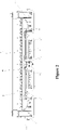
- Figure 1 is a schematic view showing the structure of a suspension frame of a magnetic levitation vehicle according to an embodiment of the present application
- Figure 2 is a front view of the suspension frame shown in Figure 1
- Figure 3 is a left view of the suspension frame shown in Figure 2
- Figure 4 is a partially enlarged view of a longitudinal beam body of the suspension frame at an end position shown in Figure 1
- Figure 5 is a partially enlarged view of a longitudinal beam body of the suspension frame at an end position shown in Figure 1 viewed from another angle.
- the suspension frame assembly of the magnetic levitation vehicle includes multiple suspension frames 100 which are sequentially connected, and each of the suspension frames 100 is arranged corresponding to a vehicle body 200 of the magnetic levitation vehicle.
- each of the suspension frames 100 of the suspension frame assembly includes:
- the supporting wheel 3 can be fixed to a mounting frame, and the mounting frame is fixedly connected to the longitudinal beam body 1 in a detachable manner by bolts or the like.
- Two anti-rolling devices 4 are mounted between the mounting frames of two of the supporting wheels 3 at the same end of the two longitudinal beam bodies 1.
- suspension frames shown in Figures 1 to 5 do not show the structure of the air-spring arm beam.
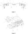
- FIG. 6 it is a schematic view showing the structure of the suspension frame assembly, in which, as an example, the suspension frame assembly is formed by five sequentially connected suspension frames.
- the two longitudinal beam bodies 1 of one of the suspension frames 100 are respectively hingedly connected to the two longitudinal beam bodies 1 of an adjacent suspension frame 100, an air-spring arm beam 8 for mounting an air spring is provided at the hinged part of the two adjacent suspension frames 100, and the air-spring arm beam 8 is mounted on the holding arm 11 of one of the two longitudinal beam bodies 1 that are hingedly connected.
- each holding arm 11 of the two longitudinal beam bodies 1 at two ends of the suspension frame assembly is mounted with the air-spring arm beam 8 for mounting the air spring.
- Reference numerals S1 to S12 in Figure 6 denote the mounting positions of the air springs, and it is understood that the figure simply shows the mounting positions of the air springs.
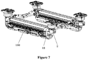
- the air-spring arm beam 8 may be provided at each of the four corners of the suspension frame 100 at the end portions of the suspension frame assembly, that is, at both ends of the two longitudinal beam bodies 1, and as shown in Figure 7 , the air-spring arm beam 8 is mounted on the holding arm 11.
- the number of the air-spring arm beams 8 arranged on each of the suspension frames 100 may vary as long as the above requirements are met.
- the structural design of the air-spring arm beam 8 and the air spring can carry part of the load in the situation when there is no suspension force or the adjacent suspension frame 100 fails, and can also solve the safety problem of the degraded operation of the adjacent suspension frame 100 in the event of failure.
- the suspension frame assembly of the magnetic levitation vehicle includes multiple suspension frames 100 which are sequentially connected.
- a supporting wheel 3 is fixed at both ends of each of the longitudinal beam bodies 1.
- the supporting wheel 3 with the fixed form can save the hydraulic structure, which helps to reduce the overall weight of the single suspension frame 100, thereby reducing the overall weight of the suspension frame assembly.
- an air-spring arm beam 8 for mounting an air spring is provided at a hinged part of the two adjacent suspension frames 100, and each holding arm of the two longitudinal beam bodies at both ends of the suspension frame assembly are mounted with the air-spring arm beam 8 for mounting the air spring.
- the number of the air springs can be greatly reduced, and the overall weight of the suspension frame assembly can be further reduced, and in conjunction with the above supporting wheel with the fixed form, the suspension frame assembly is more lightweight, thereby improving the suspension capability.
- the reduction in the number of the air springs is also advantageous for the cooperative control of the air springs, improving the flexibility of the control of the magnetic levitation vehicle.
- Each of the longitudinal beam bodies 1 is further provided with a suspension magnet module 2, and the suspension magnet module 2 extends in the length direction of each of the longitudinal beam bodies 1, and two end portions of the suspension magnet module 2 are fixedly connected to the two holding arms 11 of the corresponding longitudinal beam body 1, respectively.
- two ends of the suspension magnet module 2 may be fixed to the lower ends of the holding arms 11 by bolt connection.
- an anti-vibration plate 12 is provided on a middle portion of the suspension magnet module 2, and the anti-vibration plate 12 made of forged aluminum material is symmetrically arranged with respect to the middle portion of the suspension magnet module 2, and is directly fixed on the suspension magnet module by bolt connection, to prevent the magnetic levitation vehicle from generating lateral vibration in the curve section and from increasing rigidity.
- each of two sides of the anti-rolling device 4 is connected to the mounting frame of the supporting wheel 3 at the corresponding side by a diagonal pull rod 42 and a horizontal pull rod 41.
- the diagonal pull rod 42 is hingedly connected to the mounting frame of the supporting wheel 3 by a ball joint bearing for the diagonal pull rod to make the diagonal pull rod 42 have a predetermined rotation angle adjustment range
- the horizontal pull rod 41 is hingedly connected to the mounting frame of the supporting wheel 3 by a ball joint bearing for the horizontal pull rod, to make the horizontal pull rod 41 have a predetermined rotation angle adjustment range.
- the anti-rolling devices 4 can flexibly adjust the posture of the suspension frame assembly in the curve section, and can avoid the fluctuation of the suspension gap between the F type rail magnetic pole surface and the suspension magnets at both sides of the suspension frame assembly, thereby eliminating the influence on the suspension force attenuation, and improving the safe passing capability of the vehicle in the curve section.
- two ear plates at corresponding positions and spaced by a certain interval are provided on the mounting frame of the supporting wheel 3.
- the end of the horizontal pull rod 41 is inserted between the corresponding two ear plates, and the horizontal pull rod 41 and the two ear plates are connected by a pin.
- the ball joint bearing for the horizontal pull rod is provided at the connection position, and has a rotation angle adjustment range of about 6 degrees.
- the specific mounting form of the diagonal pull rod 42 can be similar to this, and will not be described again, and the ball joint bearing of the diagonal pull rod also has a rotation angle adjustment range of about 6 degrees.
- a lateral stop 7 is mounted on opposite sides of the two holding arms 11 of each of the longitudinal beam bodies 1, and a distance from the lateral stop 7 to an end of the suspension magnet module 2 at the corresponding side is 1/5 of the length of the suspension magnet module 2.
- a brake caliper 6 is mounted on a middle of each of the longitudinal beam bodies 1, and a pull rod 61 is provided on both sides of the brake caliper 6.
- the pull rod 61 has one end hingedly connected to the brake caliper 6, and another end hingedly connected to the lateral stop 7 at the corresponding side, to maintain the transmission of braking force during braking of the vehicle.
- a wear-resistant member 71 is fixed on an inner side of the lateral stop 7, to alleviate the wear of the lateral stop 7 and to extend the service life of the lateral stop 7.
- the wear-resistant member 71 can be specifically fastened to the lateral stop 7 by a fixing piece and a screw, to facilitate replacement of the wear-resistant member 71.
- the holding arm 11 can be made of forged aluminum, which facilitates processing and reduces the weight.
- the mounting structure of the lateral stop 7 can be directly forged on the holding arm 11 made of forged aluminum, and the lateral stop 7 is directly mounted and fixed on the holding arm 11.
- the structure of the present solution can avoid the situation that the magnetic resistance increases when the vehicle is traveling because of the lateral stop being attracted to the F type rail.
- each of the longitudinal beam bodies 1 is further provided with a traction linear motor 5 extending along a length direction of the longitudinal beam body 1, and the traction linear motor 5 is provided for providing longitudinal thrust.
- a linear motor beam 13 is mounted between the two holding arms 11 of the longitudinal beam body 1 and the traction linear motor 5 is mounted on the linear motor beam 13.
- the linear motor beam 13 can be embodied as an extruded aluminum profile structure, which facilitates processing, has a reliable structure and a light weight.
Landscapes
- Engineering & Computer Science (AREA)
- Mechanical Engineering (AREA)
- Transportation (AREA)
- Physics & Mathematics (AREA)
- Electromagnetism (AREA)
- Power Engineering (AREA)
- Vehicle Body Suspensions (AREA)
- Control Of Vehicles With Linear Motors And Vehicles That Are Magnetically Levitated (AREA)
Claims (9)
- Aufhängungsrahmenbaugruppe für ein Magnetschwebefahrzeug, aufweisend:
eine Vielzahl von Aufhängungsrahmen (100), die nacheinander verbunden sind; und wobei jeder der Aufhängungsrahmen (100) aufweist:zwei längsverlaufende Balkenkörper (1), die parallel angeordnet sind, wobei ein Stützrad (3) und ein Haltearm (11) feststehend an beiden Enden von jeder der längsverlaufenden Balkenkörper (1) bereitgestellt sind;zwei Anti-Roll-Vorrichtungen (4), die zwischen Montagerahmen von zwei der Stützräder (3) an einem selben Ende der zwei längsverlaufenden Balkenkörper (1) montiert sind; undwobei die zwei längsverlaufenden Balkenkörper (1) von einem der Aufhängungsrahmen (100) jeweils schwenkbar mit den zwei längsverlaufenden Balkenkörper (1) eines benachbarten Aufhängungsrahmen (100) verbunden sind;wobei jeder der zwei Aufhängungsrahmen (100) ferner aufweist:
zwei Aufhängungsmagnetmodule (2), die entsprechend an den zwei längsverlaufenden Balkenkörper (1) bereitgestellt sind, und zwei Enden von jedem der Aufhängungsmagnetmodule (2) feststehend mit den Haltearmen (11) an den entsprechenden Seiten verbunden sind; dadurch gekennzeichnet, dass jeder der Aufhängungsarme (100) ferner aufweist:einen Luftfederarmbalken (8) zum Montieren einer einzelnen Luftfeder an einem schwenkbaren Teil der zwei Aufhängungsrahmen (100) bereitgestellt ist und der Luftfederarmbalken (8) an den Haltearm (11) von einem der zwei längsverlaufenden Balkenkörper (1) montiert ist, die schwenkbar verbunden sind; undjeder Haltearm (11) der zwei längsverlaufenden Balkenkörper (1) an beiden Enden der Aufhängungsrahmenbaugruppe mit dem Luftfederarmbalken (8) zum Montieren der Luftfeder montiert ist, wobeider Luftfederarmbalken (8) ebenfalls an einem benachbarten Haltearm (11) des benachbarten Aufhängungsrahmens (100) montiert ist. - Aufhängungsrahmenbaugruppe nach Anspruch 1, wobei beide Seiten von jeder der Anti-Roll-Vorrichtungen (4) jeweils mit dem Aufhängungsrahmen des Stützrads (3) an einer entsprechenden Seite durch eine diagonale Zugstange (42) und eine horizontale Zugstange (41) verbunden sind.
- Aufhängungsrahmenbaugruppe nach Anspruch 2, wobei die diagonale Zugstange (42) schwenkbar mit dem Montagerahmen des Stützrads (3) durch ein Kugelgelenklager für die diagonale Zugstange verbunden ist, um es der diagonalen Zugstange (42) zu ermöglichen, einen vorbestimmten Drehwinkeleinstellbereich zu haben; die horizontale Zugstange (41) mit dem Montagerahmen des Stützrads (3) durch ein Kugelgelenklager für die horizontale Zugstange schwenkbar verbunden ist, um es der horizontalen Zugstange (41) zu ermöglichen, einen vorbestimmten Drehwinkeleinstellbereich zu haben.
- Aufhängungsrahmenbaugruppe nach Anspruch 1, wobei ein Seitenanschlag (7) an jeder von gegenüberliegenden Seiten der zwei Haltearme (11) von jeder der längsverlaufende Balkenkörper (1) montiert ist und ein Abstand von dem Seitenanschlag (7) zu einem Ende des Aufhängungsmagnetmoduls (2) auf einer entsprechenden Seite 1/5 einer Länge des Aufhängungsmagnetmoduls (2) ist.
- Aufhängungsrahmenbaugruppe nach Anspruch 4, wobei eine Bremszange (6) an einen Mittelabschnitt von jeder der längsverlaufenden Balkenkörper (1) montiert ist, eine Zugstange (61) auf beiden Seiten der Bremszange (6) bereitgestellt ist, und ein Ende der Zugstange (61) schwenkbar mit der Bremszange (6) verbunden ist und ein anderes Ende davon schwenkbar mit dem Seitenanschlag (7) auf einer entsprechenden Seite verbunden ist.
- Aufhängungsrahmenbaugruppe nach Anspruch 4, wobei ein verschleißbeständiges Element (71) an einer Innenseite des Seitenanschlags (7) befestigt ist.
- Aufhängungsrahmenbaugruppe nach Anspruch 1, wobei eine Anti-Schwingungs-Platte (12) an einem Mittelabschnitt von jedem der Aufhängungsmagnetmodule (2) bereitgestellt ist.
- Aufhängungsrahmenbaugruppe nach einem der Ansprüche 1 bis 6, wobei jeder der längsverlaufenden Balkenkörper (1) ferner mit einem Traktionslinearmotor (5) versehen ist, der sich entlang einer Längsrichtung der längsverlaufenden Balkenkörper (1) erstreckt.
- Aufhängungsrahmenbaugruppe nach Anspruch 8, wobei jeder der längsverlaufenden Balkenkörper (1) einen Linearmotorbalken (13) aufweist, der zwischen den zwei Haltearmen (11) montiert ist und konfiguriert ist, den Traktionslinearmotor (5) zu montieren.
Applications Claiming Priority (2)
| Application Number | Priority Date | Filing Date | Title |
|---|---|---|---|
| CN201710656775.8A CN107599888B (zh) | 2017-08-03 | 2017-08-03 | 磁浮车辆的悬浮架组件 |
| PCT/CN2018/085429 WO2019024554A1 (zh) | 2017-08-03 | 2018-05-03 | 磁浮车辆的悬浮架组件 |
Publications (3)
| Publication Number | Publication Date |
|---|---|
| EP3608154A1 EP3608154A1 (de) | 2020-02-12 |
| EP3608154A4 EP3608154A4 (de) | 2020-12-30 |
| EP3608154B1 true EP3608154B1 (de) | 2022-08-17 |
Family
ID=61064668
Family Applications (1)
| Application Number | Title | Priority Date | Filing Date |
|---|---|---|---|
| EP18840954.4A Active EP3608154B1 (de) | 2017-08-03 | 2018-05-03 | Aufhängungsrahmen für magnetschwebefahrzeug |
Country Status (8)
| Country | Link |
|---|---|
| US (1) | US11577614B2 (de) |
| EP (1) | EP3608154B1 (de) |
| JP (1) | JP6842569B2 (de) |
| CN (1) | CN107599888B (de) |
| CA (1) | CA3061419C (de) |
| ES (1) | ES2926198T3 (de) |
| RU (1) | RU2728890C1 (de) |
| WO (1) | WO2019024554A1 (de) |
Families Citing this family (13)
| Publication number | Priority date | Publication date | Assignee | Title |
|---|---|---|---|---|
| CN107599888B (zh) | 2017-08-03 | 2019-08-27 | 中车青岛四方机车车辆股份有限公司 | 磁浮车辆的悬浮架组件 |
| CN108382263A (zh) * | 2018-01-11 | 2018-08-10 | 同济大学 | 一种中低速磁浮列车磁铁电机一体化模块 |
| CN108556679A (zh) * | 2018-06-12 | 2018-09-21 | 湖南磁浮技术研究中心有限公司 | 中低速磁悬浮列车、走行部及采用v型组合的搭接结构 |
| CN108657194B (zh) * | 2018-07-12 | 2024-02-09 | 中铁宝桥集团有限公司 | 一种磁浮列车直线电机定位装置 |
| CN110962621A (zh) * | 2018-09-30 | 2020-04-07 | 中车唐山机车车辆有限公司 | 一种磁浮车辆及其悬浮架组件 |
| CN109228884B (zh) * | 2018-10-11 | 2020-05-05 | 湖南磁浮技术研究中心有限公司 | 一种磁悬浮列车及其悬浮架 |
| CN110758109A (zh) * | 2019-11-07 | 2020-02-07 | 中国铁建重工集团股份有限公司 | 悬浮架组件和磁浮轨道列车 |
| CN111824198B (zh) * | 2020-07-13 | 2021-06-08 | 上海园菱机械实业有限公司 | 一种磁悬浮车辆的防侧倾转向架及其防侧倾装置 |
| CN112124085B (zh) * | 2020-09-27 | 2022-03-18 | 中车唐山机车车辆有限公司 | 磁悬浮车厢及磁悬浮列车 |
| CN113997969B (zh) * | 2021-10-28 | 2023-03-14 | 中车青岛四方机车车辆股份有限公司 | 一种托臂结构及磁浮列车 |
| CN114537152B (zh) * | 2022-02-23 | 2024-02-06 | 中车株洲电力机车有限公司 | 一种磁浮车辆系统 |
| CN114938093B (zh) * | 2022-05-26 | 2025-07-15 | 湖南凌翔磁浮科技有限责任公司 | 一种磁悬浮列车的电机气隙调节结构 |
| CN116767289B (zh) * | 2023-01-30 | 2025-10-21 | 金华送变电工程有限公司 | 一种钢结构装配式变电站辅助安装小车 |
Family Cites Families (17)
| Publication number | Priority date | Publication date | Assignee | Title |
|---|---|---|---|---|
| JPS6023565B2 (ja) * | 1980-09-17 | 1985-06-08 | 日本航空株式会社 | 吸引式磁気浮上走行体の懸架装置 |
| DE3637844A1 (de) | 1986-11-06 | 1988-05-19 | Messerschmitt Boelkow Blohm | Schienenfahrzeug mit spurkranzraedern |
| JP3305377B2 (ja) * | 1992-11-13 | 2002-07-22 | 東海旅客鉄道株式会社 | 浮上式鉄道用車両 |
| JP3697492B2 (ja) * | 1995-10-31 | 2005-09-21 | 中部エイチ・エス・エス・ティ開発株式会社 | 磁気浮上式鉄道のブレーキ装置 |
| DE102004013690A1 (de) * | 2004-03-18 | 2005-10-06 | Thyssenkrupp Transrapid Gmbh | Magnetschwebefahrzeug mit Luftfedersteuerung |
| JP2007091039A (ja) * | 2005-09-29 | 2007-04-12 | Jamco Corp | 常電導吸引型磁気浮上式車両 |
| CN100431890C (zh) * | 2006-03-29 | 2008-11-12 | 上海磁浮交通工程技术研究中心 | 城轨磁浮车辆走行机构搭接装置 |
| CN101062662A (zh) * | 2007-06-01 | 2007-10-31 | 成都飞机工业(集团)有限责任公司 | F轨车辆走行机构 |
| JP5322479B2 (ja) * | 2008-04-04 | 2013-10-23 | 株式会社ジャムコ | 常電導吸引型磁気浮上式車両 |
| JP2009255603A (ja) * | 2008-04-11 | 2009-11-05 | Jamco Corp | 常電導吸引型磁気浮上式車両 |
| CN101624054B (zh) * | 2009-08-06 | 2011-03-02 | 上海磁浮交通发展有限公司 | 磁浮式轨道巡检车的走行结构 |
| DE102009058974A1 (de) * | 2009-12-18 | 2011-06-22 | Audi Ag, 85057 | Magnetschweberad |
| CN101954913B (zh) * | 2010-10-13 | 2012-06-06 | 上海磁浮交通发展有限公司 | 一种无纵梁且横梁上设置有牵引机构的悬浮架 |
| JP5877959B2 (ja) * | 2011-04-21 | 2016-03-08 | 公益財団法人鉄道総合技術研究所 | 超電導磁石装置の台車枠取付状態の診断方法及びその台車組立体 |
| RU2611858C1 (ru) * | 2015-09-24 | 2017-03-01 | Акционерное Общество "Нииэфа Им. Д.В. Ефремова" | Регулируемый магнитный подвес транспортного средства с коррекцией подъемной силы |
| CN106476832B (zh) * | 2016-12-07 | 2018-12-14 | 中车株洲电力机车有限公司 | 一种磁浮轨道车辆及其转向架 |
| CN107599888B (zh) * | 2017-08-03 | 2019-08-27 | 中车青岛四方机车车辆股份有限公司 | 磁浮车辆的悬浮架组件 |
-
2017
- 2017-08-03 CN CN201710656775.8A patent/CN107599888B/zh active Active
-
2018
- 2018-05-03 EP EP18840954.4A patent/EP3608154B1/de active Active
- 2018-05-03 ES ES18840954T patent/ES2926198T3/es active Active
- 2018-05-03 CA CA3061419A patent/CA3061419C/en active Active
- 2018-05-03 RU RU2019138539A patent/RU2728890C1/ru active
- 2018-05-03 JP JP2019564167A patent/JP6842569B2/ja active Active
- 2018-05-03 US US16/616,963 patent/US11577614B2/en active Active
- 2018-05-03 WO PCT/CN2018/085429 patent/WO2019024554A1/zh not_active Ceased
Also Published As
| Publication number | Publication date |
|---|---|
| EP3608154A4 (de) | 2020-12-30 |
| CA3061419A1 (en) | 2019-10-24 |
| ES2926198T3 (es) | 2022-10-24 |
| CN107599888B (zh) | 2019-08-27 |
| US20200254884A1 (en) | 2020-08-13 |
| EP3608154A1 (de) | 2020-02-12 |
| JP2020520845A (ja) | 2020-07-16 |
| RU2728890C1 (ru) | 2020-07-31 |
| CN107599888A (zh) | 2018-01-19 |
| WO2019024554A1 (zh) | 2019-02-07 |
| JP6842569B2 (ja) | 2021-03-17 |
| CA3061419C (en) | 2022-08-09 |
| US11577614B2 (en) | 2023-02-14 |
Similar Documents
| Publication | Publication Date | Title |
|---|---|---|
| EP3608154B1 (de) | Aufhängungsrahmen für magnetschwebefahrzeug | |
| JP2018514440A (ja) | 複合スプリング補償式サスペンション装置 | |
| CN112550340B (zh) | 转向架及轨道车辆 | |
| EP2280895B1 (de) | Aktives führungs- und ausgleichssystem für einen aufzug | |
| US11554675B2 (en) | Maglev train and moving part thereof | |
| EP2735489A1 (de) | Einstellbares lenkgestell für ein schienenfahrzeug | |
| CN107635841B (zh) | 用于将磁段联接到轨道车辆的至少一个轴的模块化装置 | |
| CN216805648U (zh) | 一种agv底盘的自适应悬挂结构 | |
| CN106809221A (zh) | 转向架总成以及轨道车辆 | |
| CN112626940B (zh) | 超导磁体连接装置及超导电动磁悬浮车辆轨道系统 | |
| CN111907284A (zh) | 车架机构和工程车辆 | |
| CN117984799A (zh) | 磁浮车辆走行机构及磁浮车辆 | |
| CN214731950U (zh) | 一种重载悬挂输送系统用驱动机构 | |
| CN212473651U (zh) | 副车架和机动车 | |
| CN112519819B (zh) | 转向架及轨道车辆 | |
| CN117775053A (zh) | 一种磁浮车辆走行部 | |
| CN112124086A (zh) | 一种导向电磁铁的防护机构及磁浮车辆 | |
| CN223116610U (zh) | 一种传动轴的减振吊架结构 | |
| CN223370542U (zh) | 一种卡车二桥板簧后支架 | |
| CN214326843U (zh) | 一种便于生产维护的滚轮导靴 | |
| CN220376149U (zh) | 一种新型起重机的鞍座结构 | |
| CN211280499U (zh) | 一种车轴可调空气悬挂主梁轴限位装置 | |
| CN202130455U (zh) | 动力加载车横向锁死装置 | |
| HK1243387A1 (en) | Modular device for coupling a magnetic segment to at least one axle of a rail vehicle | |
| CN120024781A (zh) | 一种钢丝绳悬挂用张紧调节装置 |
Legal Events
| Date | Code | Title | Description |
|---|---|---|---|
| STAA | Information on the status of an ep patent application or granted ep patent |
Free format text: STATUS: THE INTERNATIONAL PUBLICATION HAS BEEN MADE |
|
| PUAI | Public reference made under article 153(3) epc to a published international application that has entered the european phase |
Free format text: ORIGINAL CODE: 0009012 |
|
| STAA | Information on the status of an ep patent application or granted ep patent |
Free format text: STATUS: REQUEST FOR EXAMINATION WAS MADE |
|
| 17P | Request for examination filed |
Effective date: 20191108 |
|
| AK | Designated contracting states |
Kind code of ref document: A1 Designated state(s): AL AT BE BG CH CY CZ DE DK EE ES FI FR GB GR HR HU IE IS IT LI LT LU LV MC MK MT NL NO PL PT RO RS SE SI SK SM TR |
|
| AX | Request for extension of the european patent |
Extension state: BA ME |
|
| DAV | Request for validation of the european patent (deleted) | ||
| DAX | Request for extension of the european patent (deleted) | ||
| A4 | Supplementary search report drawn up and despatched |
Effective date: 20201202 |
|
| RIC1 | Information provided on ipc code assigned before grant |
Ipc: B60L 13/04 20060101AFI20201126BHEP Ipc: B61B 13/08 20060101ALI20201126BHEP Ipc: B61F 5/52 20060101ALI20201126BHEP Ipc: B60L 13/03 20060101ALI20201126BHEP |
|
| GRAP | Despatch of communication of intention to grant a patent |
Free format text: ORIGINAL CODE: EPIDOSNIGR1 |
|
| STAA | Information on the status of an ep patent application or granted ep patent |
Free format text: STATUS: GRANT OF PATENT IS INTENDED |
|
| INTG | Intention to grant announced |
Effective date: 20220325 |
|
| GRAS | Grant fee paid |
Free format text: ORIGINAL CODE: EPIDOSNIGR3 |
|
| GRAA | (expected) grant |
Free format text: ORIGINAL CODE: 0009210 |
|
| STAA | Information on the status of an ep patent application or granted ep patent |
Free format text: STATUS: THE PATENT HAS BEEN GRANTED |
|
| AK | Designated contracting states |
Kind code of ref document: B1 Designated state(s): AL AT BE BG CH CY CZ DE DK EE ES FI FR GB GR HR HU IE IS IT LI LT LU LV MC MK MT NL NO PL PT RO RS SE SI SK SM TR |
|
| REG | Reference to a national code |
Ref country code: CH Ref legal event code: EP |
|
| REG | Reference to a national code |
Ref country code: DE Ref legal event code: R096 Ref document number: 602018039511 Country of ref document: DE |
|
| REG | Reference to a national code |
Ref country code: IE Ref legal event code: FG4D |
|
| REG | Reference to a national code |
Ref country code: AT Ref legal event code: REF Ref document number: 1511963 Country of ref document: AT Kind code of ref document: T Effective date: 20220915 |
|
| REG | Reference to a national code |
Ref country code: ES Ref legal event code: FG2A Ref document number: 2926198 Country of ref document: ES Kind code of ref document: T3 Effective date: 20221024 |
|
| REG | Reference to a national code |
Ref country code: NL Ref legal event code: MP Effective date: 20220817 |
|
| REG | Reference to a national code |
Ref country code: LT Ref legal event code: MG9D |
|
| PG25 | Lapsed in a contracting state [announced via postgrant information from national office to epo] |
Ref country code: SE Free format text: LAPSE BECAUSE OF FAILURE TO SUBMIT A TRANSLATION OF THE DESCRIPTION OR TO PAY THE FEE WITHIN THE PRESCRIBED TIME-LIMIT Effective date: 20220817 Ref country code: RS Free format text: LAPSE BECAUSE OF FAILURE TO SUBMIT A TRANSLATION OF THE DESCRIPTION OR TO PAY THE FEE WITHIN THE PRESCRIBED TIME-LIMIT Effective date: 20220817 Ref country code: PT Free format text: LAPSE BECAUSE OF FAILURE TO SUBMIT A TRANSLATION OF THE DESCRIPTION OR TO PAY THE FEE WITHIN THE PRESCRIBED TIME-LIMIT Effective date: 20221219 Ref country code: NO Free format text: LAPSE BECAUSE OF FAILURE TO SUBMIT A TRANSLATION OF THE DESCRIPTION OR TO PAY THE FEE WITHIN THE PRESCRIBED TIME-LIMIT Effective date: 20221117 Ref country code: NL Free format text: LAPSE BECAUSE OF FAILURE TO SUBMIT A TRANSLATION OF THE DESCRIPTION OR TO PAY THE FEE WITHIN THE PRESCRIBED TIME-LIMIT Effective date: 20220817 Ref country code: LV Free format text: LAPSE BECAUSE OF FAILURE TO SUBMIT A TRANSLATION OF THE DESCRIPTION OR TO PAY THE FEE WITHIN THE PRESCRIBED TIME-LIMIT Effective date: 20220817 Ref country code: LT Free format text: LAPSE BECAUSE OF FAILURE TO SUBMIT A TRANSLATION OF THE DESCRIPTION OR TO PAY THE FEE WITHIN THE PRESCRIBED TIME-LIMIT Effective date: 20220817 Ref country code: FI Free format text: LAPSE BECAUSE OF FAILURE TO SUBMIT A TRANSLATION OF THE DESCRIPTION OR TO PAY THE FEE WITHIN THE PRESCRIBED TIME-LIMIT Effective date: 20220817 |
|
| REG | Reference to a national code |
Ref country code: AT Ref legal event code: MK05 Ref document number: 1511963 Country of ref document: AT Kind code of ref document: T Effective date: 20220817 |
|
| PG25 | Lapsed in a contracting state [announced via postgrant information from national office to epo] |
Ref country code: PL Free format text: LAPSE BECAUSE OF FAILURE TO SUBMIT A TRANSLATION OF THE DESCRIPTION OR TO PAY THE FEE WITHIN THE PRESCRIBED TIME-LIMIT Effective date: 20220817 Ref country code: IS Free format text: LAPSE BECAUSE OF FAILURE TO SUBMIT A TRANSLATION OF THE DESCRIPTION OR TO PAY THE FEE WITHIN THE PRESCRIBED TIME-LIMIT Effective date: 20221217 Ref country code: HR Free format text: LAPSE BECAUSE OF FAILURE TO SUBMIT A TRANSLATION OF THE DESCRIPTION OR TO PAY THE FEE WITHIN THE PRESCRIBED TIME-LIMIT Effective date: 20220817 Ref country code: GR Free format text: LAPSE BECAUSE OF FAILURE TO SUBMIT A TRANSLATION OF THE DESCRIPTION OR TO PAY THE FEE WITHIN THE PRESCRIBED TIME-LIMIT Effective date: 20221118 |
|
| PG25 | Lapsed in a contracting state [announced via postgrant information from national office to epo] |
Ref country code: SM Free format text: LAPSE BECAUSE OF FAILURE TO SUBMIT A TRANSLATION OF THE DESCRIPTION OR TO PAY THE FEE WITHIN THE PRESCRIBED TIME-LIMIT Effective date: 20220817 Ref country code: RO Free format text: LAPSE BECAUSE OF FAILURE TO SUBMIT A TRANSLATION OF THE DESCRIPTION OR TO PAY THE FEE WITHIN THE PRESCRIBED TIME-LIMIT Effective date: 20220817 Ref country code: DK Free format text: LAPSE BECAUSE OF FAILURE TO SUBMIT A TRANSLATION OF THE DESCRIPTION OR TO PAY THE FEE WITHIN THE PRESCRIBED TIME-LIMIT Effective date: 20220817 Ref country code: CZ Free format text: LAPSE BECAUSE OF FAILURE TO SUBMIT A TRANSLATION OF THE DESCRIPTION OR TO PAY THE FEE WITHIN THE PRESCRIBED TIME-LIMIT Effective date: 20220817 Ref country code: AT Free format text: LAPSE BECAUSE OF FAILURE TO SUBMIT A TRANSLATION OF THE DESCRIPTION OR TO PAY THE FEE WITHIN THE PRESCRIBED TIME-LIMIT Effective date: 20220817 |
|
| REG | Reference to a national code |
Ref country code: DE Ref legal event code: R097 Ref document number: 602018039511 Country of ref document: DE |
|
| PG25 | Lapsed in a contracting state [announced via postgrant information from national office to epo] |
Ref country code: SK Free format text: LAPSE BECAUSE OF FAILURE TO SUBMIT A TRANSLATION OF THE DESCRIPTION OR TO PAY THE FEE WITHIN THE PRESCRIBED TIME-LIMIT Effective date: 20220817 Ref country code: EE Free format text: LAPSE BECAUSE OF FAILURE TO SUBMIT A TRANSLATION OF THE DESCRIPTION OR TO PAY THE FEE WITHIN THE PRESCRIBED TIME-LIMIT Effective date: 20220817 |
|
| PLBE | No opposition filed within time limit |
Free format text: ORIGINAL CODE: 0009261 |
|
| STAA | Information on the status of an ep patent application or granted ep patent |
Free format text: STATUS: NO OPPOSITION FILED WITHIN TIME LIMIT |
|
| PG25 | Lapsed in a contracting state [announced via postgrant information from national office to epo] |
Ref country code: AL Free format text: LAPSE BECAUSE OF FAILURE TO SUBMIT A TRANSLATION OF THE DESCRIPTION OR TO PAY THE FEE WITHIN THE PRESCRIBED TIME-LIMIT Effective date: 20220817 |
|
| 26N | No opposition filed |
Effective date: 20230519 |
|
| PG25 | Lapsed in a contracting state [announced via postgrant information from national office to epo] |
Ref country code: SI Free format text: LAPSE BECAUSE OF FAILURE TO SUBMIT A TRANSLATION OF THE DESCRIPTION OR TO PAY THE FEE WITHIN THE PRESCRIBED TIME-LIMIT Effective date: 20220817 |
|
| REG | Reference to a national code |
Ref country code: CH Ref legal event code: PL |
|
| PG25 | Lapsed in a contracting state [announced via postgrant information from national office to epo] |
Ref country code: MC Free format text: LAPSE BECAUSE OF FAILURE TO SUBMIT A TRANSLATION OF THE DESCRIPTION OR TO PAY THE FEE WITHIN THE PRESCRIBED TIME-LIMIT Effective date: 20220817 |
|
| REG | Reference to a national code |
Ref country code: BE Ref legal event code: MM Effective date: 20230531 |
|
| PG25 | Lapsed in a contracting state [announced via postgrant information from national office to epo] |
Ref country code: MC Free format text: LAPSE BECAUSE OF FAILURE TO SUBMIT A TRANSLATION OF THE DESCRIPTION OR TO PAY THE FEE WITHIN THE PRESCRIBED TIME-LIMIT Effective date: 20220817 Ref country code: LU Free format text: LAPSE BECAUSE OF NON-PAYMENT OF DUE FEES Effective date: 20230503 Ref country code: LI Free format text: LAPSE BECAUSE OF NON-PAYMENT OF DUE FEES Effective date: 20230531 Ref country code: CH Free format text: LAPSE BECAUSE OF NON-PAYMENT OF DUE FEES Effective date: 20230531 |
|
| REG | Reference to a national code |
Ref country code: IE Ref legal event code: MM4A |
|
| PG25 | Lapsed in a contracting state [announced via postgrant information from national office to epo] |
Ref country code: IE Free format text: LAPSE BECAUSE OF NON-PAYMENT OF DUE FEES Effective date: 20230503 |
|
| PG25 | Lapsed in a contracting state [announced via postgrant information from national office to epo] |
Ref country code: IE Free format text: LAPSE BECAUSE OF NON-PAYMENT OF DUE FEES Effective date: 20230503 |
|
| PG25 | Lapsed in a contracting state [announced via postgrant information from national office to epo] |
Ref country code: BE Free format text: LAPSE BECAUSE OF NON-PAYMENT OF DUE FEES Effective date: 20230531 |
|
| PG25 | Lapsed in a contracting state [announced via postgrant information from national office to epo] |
Ref country code: BG Free format text: LAPSE BECAUSE OF FAILURE TO SUBMIT A TRANSLATION OF THE DESCRIPTION OR TO PAY THE FEE WITHIN THE PRESCRIBED TIME-LIMIT Effective date: 20220817 |
|
| PG25 | Lapsed in a contracting state [announced via postgrant information from national office to epo] |
Ref country code: BG Free format text: LAPSE BECAUSE OF FAILURE TO SUBMIT A TRANSLATION OF THE DESCRIPTION OR TO PAY THE FEE WITHIN THE PRESCRIBED TIME-LIMIT Effective date: 20220817 |
|
| PGFP | Annual fee paid to national office [announced via postgrant information from national office to epo] |
Ref country code: FR Payment date: 20250305 Year of fee payment: 8 |
|
| PGFP | Annual fee paid to national office [announced via postgrant information from national office to epo] |
Ref country code: GB Payment date: 20250305 Year of fee payment: 8 |
|
| PGFP | Annual fee paid to national office [announced via postgrant information from national office to epo] |
Ref country code: DE Payment date: 20250519 Year of fee payment: 8 |
|
| PGFP | Annual fee paid to national office [announced via postgrant information from national office to epo] |
Ref country code: ES Payment date: 20250616 Year of fee payment: 8 |
|
| PGFP | Annual fee paid to national office [announced via postgrant information from national office to epo] |
Ref country code: IT Payment date: 20250530 Year of fee payment: 8 |
|
| PG25 | Lapsed in a contracting state [announced via postgrant information from national office to epo] |
Ref country code: CY Free format text: LAPSE BECAUSE OF FAILURE TO SUBMIT A TRANSLATION OF THE DESCRIPTION OR TO PAY THE FEE WITHIN THE PRESCRIBED TIME-LIMIT; INVALID AB INITIO Effective date: 20180503 |
|
| PG25 | Lapsed in a contracting state [announced via postgrant information from national office to epo] |
Ref country code: HU Free format text: LAPSE BECAUSE OF FAILURE TO SUBMIT A TRANSLATION OF THE DESCRIPTION OR TO PAY THE FEE WITHIN THE PRESCRIBED TIME-LIMIT; INVALID AB INITIO Effective date: 20180503 |