EP3607374B1 - Dispositif de positionnement cartésien et tête d'usinage au laser équipée de celui-ci - Google Patents
Dispositif de positionnement cartésien et tête d'usinage au laser équipée de celui-ci Download PDFInfo
- Publication number
- EP3607374B1 EP3607374B1 EP18716234.2A EP18716234A EP3607374B1 EP 3607374 B1 EP3607374 B1 EP 3607374B1 EP 18716234 A EP18716234 A EP 18716234A EP 3607374 B1 EP3607374 B1 EP 3607374B1
- Authority
- EP
- European Patent Office
- Prior art keywords
- slide
- guide
- optical system
- positioning device
- adjusting
- Prior art date
- Legal status (The legal status is an assumption and is not a legal conclusion. Google has not performed a legal analysis and makes no representation as to the accuracy of the status listed.)
- Active
Links
- 238000003754 machining Methods 0.000 title claims description 9
- 230000003287 optical effect Effects 0.000 claims description 65
- 230000005540 biological transmission Effects 0.000 claims description 39
- 238000012545 processing Methods 0.000 description 19
- 238000006073 displacement reaction Methods 0.000 description 6
- 238000013461 design Methods 0.000 description 4
- 238000000034 method Methods 0.000 description 4
- 238000004519 manufacturing process Methods 0.000 description 2
- 238000012546 transfer Methods 0.000 description 2
- 230000015572 biosynthetic process Effects 0.000 description 1
- 238000011161 development Methods 0.000 description 1
- 230000018109 developmental process Effects 0.000 description 1
- 239000000428 dust Substances 0.000 description 1
- 230000001771 impaired effect Effects 0.000 description 1
- 238000003698 laser cutting Methods 0.000 description 1
- 239000000463 material Substances 0.000 description 1
- 239000013307 optical fiber Substances 0.000 description 1
- 239000002245 particle Substances 0.000 description 1
- 238000007789 sealing Methods 0.000 description 1
- 238000007493 shaping process Methods 0.000 description 1
- 238000003466 welding Methods 0.000 description 1
Images


Classifications
-
- B—PERFORMING OPERATIONS; TRANSPORTING
- B23—MACHINE TOOLS; METAL-WORKING NOT OTHERWISE PROVIDED FOR
- B23K—SOLDERING OR UNSOLDERING; WELDING; CLADDING OR PLATING BY SOLDERING OR WELDING; CUTTING BY APPLYING HEAT LOCALLY, e.g. FLAME CUTTING; WORKING BY LASER BEAM
- B23K26/00—Working by laser beam, e.g. welding, cutting or boring
- B23K26/70—Auxiliary operations or equipment
- B23K26/702—Auxiliary equipment
-
- G—PHYSICS
- G02—OPTICS
- G02B—OPTICAL ELEMENTS, SYSTEMS OR APPARATUS
- G02B7/00—Mountings, adjusting means, or light-tight connections, for optical elements
- G02B7/003—Alignment of optical elements
- G02B7/004—Manual alignment, e.g. micromanipulators
-
- B—PERFORMING OPERATIONS; TRANSPORTING
- B23—MACHINE TOOLS; METAL-WORKING NOT OTHERWISE PROVIDED FOR
- B23K—SOLDERING OR UNSOLDERING; WELDING; CLADDING OR PLATING BY SOLDERING OR WELDING; CUTTING BY APPLYING HEAT LOCALLY, e.g. FLAME CUTTING; WORKING BY LASER BEAM
- B23K26/00—Working by laser beam, e.g. welding, cutting or boring
- B23K26/70—Auxiliary operations or equipment
-
- G—PHYSICS
- G02—OPTICS
- G02B—OPTICAL ELEMENTS, SYSTEMS OR APPARATUS
- G02B27/00—Optical systems or apparatus not provided for by any of the groups G02B1/00 - G02B26/00, G02B30/00
- G02B27/09—Beam shaping, e.g. changing the cross-sectional area, not otherwise provided for
-
- G—PHYSICS
- G02—OPTICS
- G02B—OPTICAL ELEMENTS, SYSTEMS OR APPARATUS
- G02B7/00—Mountings, adjusting means, or light-tight connections, for optical elements
- G02B7/02—Mountings, adjusting means, or light-tight connections, for optical elements for lenses
- G02B7/023—Mountings, adjusting means, or light-tight connections, for optical elements for lenses permitting adjustment
-
- G—PHYSICS
- G05—CONTROLLING; REGULATING
- G05B—CONTROL OR REGULATING SYSTEMS IN GENERAL; FUNCTIONAL ELEMENTS OF SUCH SYSTEMS; MONITORING OR TESTING ARRANGEMENTS FOR SUCH SYSTEMS OR ELEMENTS
- G05B19/00—Programme-control systems
- G05B19/02—Programme-control systems electric
- G05B19/18—Numerical control [NC], i.e. automatically operating machines, in particular machine tools, e.g. in a manufacturing environment, so as to execute positioning, movement or co-ordinated operations by means of programme data in numerical form
- G05B19/402—Numerical control [NC], i.e. automatically operating machines, in particular machine tools, e.g. in a manufacturing environment, so as to execute positioning, movement or co-ordinated operations by means of programme data in numerical form characterised by control arrangements for positioning, e.g. centring a tool relative to a hole in the workpiece, additional detection means to correct position
-
- G—PHYSICS
- G05—CONTROLLING; REGULATING
- G05B—CONTROL OR REGULATING SYSTEMS IN GENERAL; FUNCTIONAL ELEMENTS OF SUCH SYSTEMS; MONITORING OR TESTING ARRANGEMENTS FOR SUCH SYSTEMS OR ELEMENTS
- G05B2219/00—Program-control systems
- G05B2219/30—Nc systems
- G05B2219/45—Nc applications
- G05B2219/45165—Laser machining
Definitions
- the invention relates to a Cartesian positioning device for positioning an optical system and to a laser processing head for processing a workpiece by means of a laser beam, which comprises such a Cartesian positioning device.
- optics such as a lens or beam shaping optics
- optics have to be adjusted independently of one another in at least two directions.
- an optical component arranged in the laser processing head for adjusting the laser beam must be set independently of one another through a fine nozzle bore of a laser processing head in two directions perpendicular to the optical axis of the laser processing head.
- the problem here is that the optics are not displaced exactly linearly or not on axes that are perpendicular to one another. This makes precise setting difficult and the reproducibility of a desired position is impaired.
- JP 2004-361862A a condenser system for a laser processing device is shown, wherein a lens can perform a movement in a two-dimensional direction perpendicular to the optical axis.
- a lens can perform a movement in a two-dimensional direction perpendicular to the optical axis.
- two sets of micrometers and springs are arranged orthogonally to one another.
- FIG. 3 shows a positioning mechanism for optical components.
- a top plate can be adjusted in the x or z direction using an x micrometer and a z micrometer.
- the movement of the z-micrometer leads via plates of a connecting element to a movement of the top plate in the z-direction.
- Both micrometers are attached to a side plate of the housing and are adjustable along the x direction.
- FIG. 10 shows an optical fiber positioning device having a frame and a table for receiving an optical component. Below the table there is an inner plate for holding actuators that can be adjusted along a y-direction. An actuator is provided for a movement in an x-direction. For a movement in the y direction and for a pivoting movement, two further actuators are provided, the adjustment movements of which must be suitably superimposed.
- DE 23 64 026 A1 describes a device for fastening a picture carrier in a desired position with a holding frame and a picture carrier arranged therein, which is held in its desired position by means of two screws which are screwed into threaded holes on one side of the frame. A position of the image carrier in a first direction is set by turning the two screws.
- the invention is therefore based on the object of providing a Cartesian positioning device for positioning an optical system and a laser processing head with the same, wherein the optical system can be positioned in two directions independently of one another with a compact and simple design and improved ease of use.
- Cartesian positioning device for positioning an optical system according to claim 1 and a laser processing head for processing a workpiece by means of a laser beam with the same according to claim 13.
- a Cartesian positioning device for positioning an optical system comprises a first adjusting element, or y-adjusting element, for linear movement of an optical mount along a first Cartesian axis, ie in the y-direction, and a second adjusting element, or x-adjusting element, for linear movement of the optical mount along a second Cartesian axis, ie in the x direction, with both the first and the second adjusting element being adjustable along the first Cartesian axis, ie along the y direction.
- the first and second Cartesian axes, ie the y direction and the x direction are perpendicular to one another.
- the x- and y-adjusting elements can be adjusted parallel to one another.
- the adjusting elements can be designed as threaded spindles, for example. This enables a compact design and independent positioning along two Cartesian axes.
- the Cartesian axes ie the x-axis and y-axis, designate the axes of a Cartesian coordinate system, the third axis of which is the z-axis.
- the two adjusting elements are arranged next to one another on a carrier element to which the optical mount is attached. This enables clear operation and simplified accessibility.
- At least one of the two adjusting elements is calibrated.
- a specific adjustment value of one of the adjusting elements can be assigned to a specific value for the linear movement along the corresponding Cartesian axis.
- the y-adjusting element and / or the x-adjusting element can each comprise a micrometer screw. This makes positioning of the optics reproducible and simplifies exact positioning of the optics in an optical system.
- One end of the y-adjusting element is designed as a y-slide.
- One end of the x-adjusting element can also be designed as an x-slide.
- the y-slide connects the y-adjusting element with the lens mount in a moveable manner.
- the x-slide can movably connect the x-adjusting element to the lens mount.
- the x slide and / or the y slide can be guided along at least one slide guide element.
- the y-adjusting element or the y-slide is movably coupled to the optical mount by means of a linear guide unit in the x-direction.
- the y-adjusting element or the y-slide and the lens mount can be movably connected to one another via a rail or slide system.
- the linear guide unit preferably has a first part, which is arranged on one selected from the y-adjusting element (or y-slide) and the optics mount, and a second part, which is arranged on the other selected by the y-adjusting element (or y-slide) and the optics mount is arranged.
- the first part of the linear guide unit can have an undercut, in which a projection of the second part of the linear guide unit designed with a corresponding shape is guided.
- An example of the linear guide unit is a dovetail guide.
- the connection of the y-adjusting element or the y-slide with the optical mount is preferably invariant in tension and / or in pressure. This enables an exact setting of a desired position, e.g. by pulling or pushing, without being affected by play in the connection.
- a transmission element can be arranged between the x-slide and the optics mount.
- the transmission element can be movably connected in the x-direction to the carrier element or mounted therein.
- the transmission element can be movably connected to the optics mount by a first guide unit.
- the first guide unit can be designed to guide the optics mount in the y direction.
- the first guide unit comprises a linear guide unit, for example a dovetail guide.
- the first guide unit can comprise a first guide extending in the y direction, for example an elongated hole, and a first guide pin guided therein.
- the first guide can be formed in one selected from the transmission element and the optics mount and the first guide pin can be formed in the other selected from the transmission element and the optics mount.
- the transmission element can be movably connected to the x-slide by a second guide unit.
- the second guide unit can be configured to move the x-adjusting element along the y-direction into a movement of the transmission element along a predetermined direction which forms an angle of less than 90 °, preferably an angle of approximately 45 °, with the y-direction to convert.
- the second guide unit can comprise a second guide extending in the predetermined direction, for example an elongated hole, and a second guide pin guided therein.
- the second tour can be in one selected from the transmission element and the x-adjusting element (or x-slide) and the second guide pin can be formed in the other selected from the transmission element and the x-adjusting element (or x-slide).
- the second guide unit can move the transmission element and thus the optics mount in the x-direction.
- the linear adjustment movement of the x adjusting element along the y direction is preferably converted into a movement of the transmission element in the xy plane by the diagonally oriented second guide.
- the movement of the transmission element can be converted into a linear movement of the optics mount in the x direction by the linear guide unit, which couples the y-adjusting element and the optics mount to one another.
- the x-adjusting element or the x-slide can be movably coupled to the lens mount via a lever element. An adjustment of the x-adjusting element can thus be transferred to the optical mount via a lever element.
- the lever element preferably has a first end and a second end, the lever element being coupled at its first end to the x-adjusting element or the x-slide and at its second end to the carrier element.
- the lever element may be coupled to the optics mount at a point between the first end and the second end.
- the lever element can be connected to the carrier element via a swivel joint.
- the lever element is preferably attached to the carrier element such that it can pivot in the x-y plane.
- the lever element can be movably connected to the optics mount by a first guide unit.
- the lever element can also be movably connected to the x-adjusting element or to the x-slide by a second guide unit.
- the first guide unit can be set up to guide the optics mount linearly in the y-direction.
- the first guide unit preferably also allows the lever to rotate about the first guide pin.
- the second guide unit can be set up to transmit an adjustment movement of the x-adjusting element to the lever element.
- the linear adjustment movement of the x-adjusting element along the y-direction is preferably converted as a pivoting movement of the lever element in the x-y plane.
- the second guide can be bent or curved.
- the second guide unit preferably allows the lever to rotate about the second guide pin.
- the pivoting movement of the lever element can be converted into a linear movement of the optics socket in the x direction by the linear guide unit, which couples the y-adjusting element and the optical mount with one another.
- the lever element can be L-shaped.
- the lever element can be coupled to the lens mount in the area in which both legs of the L-shape are to meet.
- the first guide unit can therefore be arranged at a kink point of the L-shaped lever element.
- the L-shape of the lever element allows an even more compact design.
- a part of the first guide unit e.g. the first guide pin or the first guide, arranged on a fastening extension of the lens mount.
- the attachment extension of the optical mount can extend in the y-direction towards the carrier element. This enables a compact arrangement of the transmission elements for the x and y adjustment movements on the optics mount.
- the first guide unit can comprise a first guide pin and a first guide.
- the second guide unit can also comprise a second guide pin and a second guide.
- the first guide pin and / or the second guide pin are preferably formed on the lever element or on the transmission element. This simplifies the production processes.
- the first and / or second guide can comprise a recess, a guide groove, or a hole, in particular an elongated hole.
- the first guide is preferably formed on the lens mount.
- the second guide is preferably formed on the x-adjusting element or x-slide.
- At least one slide guide element can be provided which guides a movement of the x slide or the y slide in the y direction.
- the slide guide element can be designed as a guide pin or guide rib either on the x or y slide or on the carrier element.
- a corresponding groove or bore can be formed on the other of the x or y slide and the carrier element in which the slide guide element is guided.
- the slide guide element can also be designed as part of a dovetail guide, the other part of the dovetail guide being designed for the x or y slide.
- At least one spring element can be arranged between the optical mount and the carrier element.
- the spring element can be configured to provide a restoring force on the optics mount in the direction of the carrier element. This also serves to stabilize the movement of the lens mount.
- the restoring force of the spring element can prevent idling when changing direction.
- a laser machining head for machining a workpiece by means of a laser beam comprises a Cartesian positioning device for positioning an optical system according to one of the exemplary embodiments described.
- the optics are preferably arranged in a beam path of the laser processing head.
- the carrier element of the Cartesian positioning device can be attached to a housing of the laser processing head by means of fastening means, for example screws.
- An optical axis of the laser processing head runs preferably in the z direction of the Cartesian coordinate system, i.e. H. perpendicular to the x-y plane.
- x-direction, x-adjusting element, x-slide each have the same meaning as first direction, first adjusting element, first slide and can be replaced by them.
- y-direction, y-adjusting element, y-slide each have the same meaning as second direction, second adjusting element, second slide and can be replaced by them.
- the first or x-direction is perpendicular to the second or y-direction.
- FIG. 1 shows a schematic plan view of a Cartesian positioning device for positioning an optical system according to a first embodiment of the present invention.
- the positioning device comprises a carrier element 20, to which an optics mount 10 for holding an optics is attached.
- the carrier element 20 can be fastened to a housing of a laser processing head via fastening means 21, such as screws, for example, so that the optics can be arranged in the beam path of the laser processing head.
- the optical mount 10 can be displaced linearly along a first and a second Cartesian axis by means of two adjusting elements 30 and 40. A shift along the first Cartesian axis is independent of a shift along the second Cartesian axis.
- the two Cartesian axes are referred to below as the x-axis and y-axis and are axes of a Cartesian or orthogonal coordinate system.
- a movement in the x-direction or in the y-direction also denotes a movement along the x-axis or along the y-axis.
- a movement in the x direction is independent of a movement in the y direction and therefore has no component in the y direction.
- the first adjusting element for moving the optics mount 10 along the y-axis i.e. the y-control element 30, penetrates the carrier element 20, so that one end of the y-control element 30 from an outside of the carrier element 20 for a positioning process of the optics mount 10 in y- Direction is accessible.
- a y-slide 50 is arranged, via which the y-adjusting element 30 is coupled to the optical mount 10.
- the y-slide 50 and the optics mount 10 are movably connected to one another via a linear guide unit 15.
- the linear guide unit 15 can comprise, for example, a slide that is formed on the y-slide 50 and a rail guide that is formed on the optics mount 10.
- the linear guide unit 15 is arranged in the x-direction and allows a linear movement of the optics mount 10 in the x-direction.
- the y-slide 50 can, for example, have a dovetail groove in which a suitably shaped rail of the optical mount 10 is guided. Of course, conversely, a dovetail groove can also be provided on the lens mount 10 and the appropriate one Rail on the y-slide 50.
- the linear guide unit 15 is preferably designed such that the connection between the y-slide 50 and the optical mount 10 is invariant in tension and pressure.
- the y-slide 50 which is firmly coupled to the optics mount 10 in the y-direction, is also displaced in the y-direction and accordingly moves the optics mount 10 along by pulling or pushing the y-axis.
- the second adjusting element for moving the optical mount 10 along the x-axis i.e. the x-adjusting element 40, also penetrates the carrier element 20, so that one end of the x-adjusting element 40 from an outside of the carrier element 20 for a positioning process of the optical mount 10 in x -Direction is accessible.
- an x-slide 60 is arranged, which is movably coupled to the optics mount 10 via a lever element 70.
- the lever element 70 is fastened to the support element 20 via a swivel joint 71, so that the lever element 70 can be pivoted about the swivel joint 71 in the xy plane.
- the carrier element 20 can have a fastening extension 22 which extends from an inside of the carrier element 20 in the y-direction towards the optics mount 10 in order to facilitate a pivoting movement of the lever element 70 about the rotary joint 71.
- the lever element 70 is movably connected to the optics mount 10 via a first guide unit 80 and to the x-slide 60 via a second guide unit 90.
- the swivel joint 71 can be provided at one end of the L-shape, the first guide unit 80 at the inflection point where both legs of the L-shape meet, and the second guide unit 90 at the other end a space-saving arrangement for converting the linear adjusting movement of the x adjusting element 40 in the y direction into a pivoting movement of the lever element 70 in the xy plane.
- the first guide unit 80 comprises a first guide pin 81 which runs in a first guide 82.
- the first guide 82 extends in a straight line in the y direction.
- the first guide pin 81 is preferably formed on the lever element 70, while the first guide 82, such as a groove or an elongated hole, is formed in the optics mount 10.
- the first guide unit 80 thus allows a linear movement of the optics mount 10 in the y direction.
- the second guide unit 90 also has a second guide pin 91 which runs in a second guide 92.
- the second guide 92 such as a groove or an elongated hole, is preferably formed on the x-slide 60, while the second guide pin 91 is provided on the lever element 70.
- the invention is not limited to this.
- the formation of the first guide pin 81 and / or the second guide pin 91 on the lever element 70 simplifies production.
- the second guide 92 can be bent or curved. Both the first guide 82 and the second guide 92 permit a rotary movement of the respective first and second guide pins 81 and 91.
- the lever element 70 is pivoted about the swivel joint 71, whereby the optics mount 10, which is fixed in the y direction by the linear guide unit 15, is displaced along the linear guide unit 15 in the x direction .
- An adjusting movement of the y adjusting element 30 is transmitted directly to the optics mount 10 via the y slider 50, the optics mount 10 being guided linearly in the y direction by the first guide unit 80.
- the optics mount 10 can have a fastening extension 11, which extends from the optics mount 10 in the y-direction towards the carrier element 20.
- a part of the first guide unit 80 i. the first guide pin 81 or the first guide 82 may be arranged. This also enables a compact arrangement of the elements for transferring the adjusting movement of the x adjusting element 40 in the y direction into a movement along the x axis of the optics mount 10.
- Both the y-adjusting element 30 and the x-adjusting element 40 are axially fixed, so that a movement of the optical mount 10 in the respective other Cartesian direction is prevented. Both the y-adjusting element 30 and the x-adjusting element 40 can be adjusted parallel to one another along the y-direction.
- the x- and / or y-adjusting element is preferably calibrated so that a specific adjusting movement can be assigned an exact value of the displacement of the optical mount 10 along the corresponding Cartesian axis.
- a micrometer screw for example, can be used as the calibrated adjusting element.
- slide guide elements 23 can be provided on the carrier element 20, for example guide pins which are each in a corresponding bore of the y slide 50 or the x slide 60 run.
- the slide guide elements 23 can also be provided on the y slide 50 or on the x slide 60 and be guided in corresponding bores in the carrier element 20.
- Figure 2 shows the Cartesian positioning device Figure 1 , wherein further spring elements 18 are provided between the optical mount 10 and the carrier element 20 in order to prevent idling when changing direction.
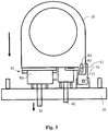
- Figure 3 shows the Cartesian positioning device Figure 1 , wherein the y-adjusting element 30 has been adjusted by a predetermined amount in the y-direction (downwards).
- the optics mount 10 which is connected to the y-adjusting element 30 via the linear guide unit 15 and the y-slide 50, is also pulled in the y-direction, the first guide pin 81 being displaced in the first guide 82.
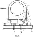
- Figure 4 shows the Cartesian positioning device Figure 1 , wherein the x-adjusting element 40 has been adjusted by a predetermined amount in the y-direction (downward).
- the lever element 70 is pivoted about the swivel joint 71 in the xy plane, the second guide pin 91 being guided along the second guide 92.
- the pivoting movement of the lever element 70 is transmitted to the optics mount 10 via the first guide unit 80 and converted into a linear x movement by the linear guide unit 15.
- FIG. 5 to 8 a second embodiment of the Cartesian positioning device according to the invention is shown.
- a diagonal displacement of a transmission element 170 is used to convert the displacement movement of the x-adjusting element 140 in the y-direction into a displacement of the optical mount 110 in the x-direction. This enables a compact, stable and play-free design.
- the positioning device comprises a carrier element 120, on which an optical mount 110 for holding an optical system is mounted so as to be adjustable in the x-direction and in the y-direction.
- the carrier element 120 can comprise fastening means 121 for fastening to a laser processing head.
- a sealing element 200 can be provided in order to protect the carrier element 120 and the laser processing head against dust particles and the like. to seal.
- a y-adjusting element 130 and an x-adjusting element 140 are provided on the carrier element 120, which can be adjusted parallel to one another in the y-direction and each have a y-slide 150 and an x-slide 160.
- a transmission element 170 is arranged on the optics mount 110 in order to convert an adjusting movement of the x-adjusting element 140 or x-slide 160, which takes place in the y-direction, into a displacement of the optics-mount 110 in the x-direction.
- a first guide 182 formed in the optical mount 110 can be seen, in which a first guide pin 181 of the transmission element 170 is guided in the y-direction. This allows the optics mount 110 to be shifted in the y direction with respect to the x slider 160.
- the y-slide 150 is connected to the optics mount 110 via a linear guide unit 115 which is set up to guide a movement of the optics mount 110 with respect to the y-slide 150 in the x-direction.
- a linear guide unit 115 which is set up to guide a movement of the optics mount 110 with respect to the y-slide 150 in the x-direction.
- an x linear guide element 111 is formed on the optics mount 110 and a corresponding x linear guide element 151 is formed on the y slide 150.
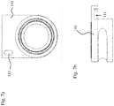
- the linear guide unit 115 may comprise a dovetail guide, as in FIG Figure 5b shown.
- the at least one spring element 118 can be arranged in order to provide a restoring force on the optics mount 110 towards the carrier element.
- the at least one spring element 118 can run around one side of the optics mount 110 and be fastened to the carrier element 120 in each case adjacent to the x slide 160 and the y slide 150.
- a slide guide element 123 can be provided which is set up for linear guidance in the y-direction.
- the slide guide element 123 can be rod-shaped and guided in a bore in the y slide 150 or the x slide 160.
- at least one dovetail guide can be formed in the slide guide element 123 in order to guide the y slide 150 or the x slide 160 in the y direction.
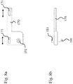
- FIGs 6a and 6b a part of a positioning device without the optics mount 110 and the transmission element 170 is shown.
- the carrier element 120 and the transmission element 170 can be coupled via an x-linear guide unit.
- the carrier element 120 can preferably have a guide slot which extends in the x direction and into which at least a part of the transmission element 170 is inserted.
- the carrier element 120 can be connected to the transmission element 170 be coupled by a dovetail guide.
- At least one fastening element 122 can furthermore be provided in the carrier element 120 in order to connect the transmission element 170 to the carrier element 120.
- FIG 6a For example, two rod-shaped fastening elements 122, such as screws or bolts, are shown, which are arranged in the guide slot of the carrier element 120.
- the fasteners 122 are in the Figure 8a
- Transfer element guides 171 shown are used to couple the transfer element 170 to the carrier element 120 movably in the x-direction.
- the transmission element 170 can have guide pins which run in a groove formed in the carrier element 120 or in the guide slot.
- a slide guide member 123 is shown with two dovetail guides to stabilize both the y-slide 150 and the x-slide 160. Of course, only one of the two slides 150 and 160 can be guided through the slide guide element 123.
- a corresponding counterpart to the guidance of the slide guide element 123 is designed as a y-linear guide element 152 in the y-slide 150 or as a y-linear guide element 161 in the x-slide 160.
- the y slide 150 can consequently comprise two linear guide elements arranged perpendicular to one another, such as the x linear guide element 151 to guide the optics mount 110 in the x direction on the y slider 150, and the y linear guide element 152 to adjust the y -Slide 150 to guide in the y-direction.
- the x slide 160 can comprise at least the y linear guide element 161 for guiding the adjustment movement of the x slide 160 in the y direction.
- one or more further linear guide elements can also be provided.
- linear guide elements acting in one another can be provided on the x slide 160 and on the y slide 150 in order to stabilize a movement relative to one another in the y direction.
- Figures 7a and 7b show views of the optics mount 110.
- the optics mount 110 has an x-linear guide element 111 which, with the x-linear guide element 151 of the y-slide 150, forms a linear guide unit.
- the optics mount 110 and the y slide 150 are coupled to one another so as to be movable in the x direction via a linear guide.
- the optical mount 110 also has a first guide 182 which guides a movement in the y direction.
- the first guide 182 is formed at an angle of 45 ° to the second guide 192 in the x-slide 160.
- a first guide pin 181 of the transmission element 170 is inserted into the first guide 182 of the optics mount 110 in order to enable a movement of the optics mount in the y direction with respect to the x slide.
- the transmission element 170 preferably has an L-shape, on one leg of which at least one transmission element guide 171, for example a (extending in the x-direction) slot or elongated hole, is formed, and on the other leg of which the first and second guide pins 181 and 191 in opposite directions Protrude directions perpendicular to the x and y directions.
- the first and second guide pins 181 and 191 are formed on opposite surfaces of the transmission member 170.
- the first and second guide pins 181 and 191 can also be formed by a bolt or by a screw which penetrates the transmission element.
- the optics mount 110 can be displaced in the y-direction when the y-slide 150 is adjusted with respect to the x-slide 160.
- the second guide pin 191 of the transmission element 170 coupled to the optics mount 110 in the diagonal guide 192 of the x slide 160 and through the linear guide unit 115, which couples the optics mount 110 and the y slider 150 movably in the x direction, an adjustment movement of the x-slide 160 in the y-direction is converted or transferred into a displacement of the optics mount 110 in the x-direction.
- concave or convex areas e.g. a linear guide or a dovetail guide, can be interchanged.
- a Cartesian positioning device can be specified which enables an exact and reproducible positioning of an optical system in the x-direction and in the y-direction, positioning in the two Cartesian directions x and y being independent of one another.
- calibrated adjusting elements such as micrometer screws
- a specific Adjusting movement or an angle of rotation of the adjusting element can be assigned an exact value of the linear movement of the optical mount 10 along the corresponding x or y axis. Since both the y-adjusting element 30 and the x-adjusting element 40 can be adjusted in the same direction, ie parallel to one another along the y-direction, both adjusting elements 30 and 40 can be arranged next to one another on the carrier element 20.
Landscapes
- Physics & Mathematics (AREA)
- Optics & Photonics (AREA)
- General Physics & Mathematics (AREA)
- Engineering & Computer Science (AREA)
- Plasma & Fusion (AREA)
- Mechanical Engineering (AREA)
- Human Computer Interaction (AREA)
- Manufacturing & Machinery (AREA)
- Automation & Control Theory (AREA)
- Mounting And Adjusting Of Optical Elements (AREA)
- Laser Beam Processing (AREA)
- Lens Barrels (AREA)
Claims (14)
- Dispositif de positionnement cartésien destiné à positionner une optique pour une tête d'usinage au laser, comportant :une monture optique (10, 110) pour maintenir l'optique ;exactement un élément d'actionnement y (30, 130) pour un mouvement linéaire de la monture optique (10, 110) dans une direction y ;exactement un élément d'actionnement x (40, 140) pour un mouvement linéaire de la monture optique (10, 100) dans une direction x ;dans lequel l'élément d'actionnement x (40, 140) et l'élément d'actionnement y (30, 130) sont agencés l'un à côté de l'autre sur un élément de support (20, 120),dans lequel l'élément d'actionnement y (30, 130) est réglable le long de la direction y afin de déplacer linéairement la monture optique (10, 110) le long de la direction y, etdans lequel l'élément d'actionnement x (40, 140) est réglable le long de la direction y afin de déplacer linéairement la monture optique (10, 110) le long de la direction x,dans lequel l'élément d'actionnement y (30, 130) comporte, à une extrémité, exactement un coulisseau y (50, 150) qui relie l'élément d'actionnement y (30, 130) à la monture optique (10, 110),dans lequel le coulisseau y (50, 150) est relié à la monture optique (10, 110) de manière mobile dans la direction x au moyen d'une unité de guidage linéaire (15, 115).
- Dispositif de positionnement cartésien selon la revendication 1, dans lequel une valeur définie pour le mouvement linéaire dans la direction y ou dans la direction x est respectivement associée à une valeur de réglage de l'élément d'actionnement y (30, 130) ou de l'élément d'actionnement x (40, 140).
- Dispositif de positionnement cartésien selon la revendication 1, dans lequel l'unité de guidage linéaire (15, 115) relie l'élément d'actionnement y (30, 130) à la monture optique (10, 110) de manière invariante par rapport à une charge de traction ou de compression le long de l'axe y.
- Dispositif de positionnement cartésien selon l'une des revendications précédentes, dans lequel l'élément d'actionnement x (40, 140) comporte, à une extrémité, un coulisseau x (60, 160) qui relie l'élément d'actionnement x (40, 140) à la monture optique (10, 110).
- Dispositif de positionnement cartésien selon la revendication 4, dans lequel le coulisseau x (60, 160) et/ou le coulisseau y (50, 150) est guidé le long d'au moins un élément de guidage de coulisseau (23, 123).
- Dispositif de positionnement cartésien selon la revendication 4 ou 5, dans lequel un élément de transmission (170) est agencé entre le coulisseau x (130) et la monture optique (110), lequel élément de transmission étant relié à l'élément de support (120) de manière mobile dans la direction x.
- Dispositif de positionnement cartésien selon la revendication 6, dans lequel l'élément de transmission (170) est relié de manière mobile à la monture optique (110) par l'intermédiaire d'une première unité de guidage (180) et au coulisseau x (130) par l'intermédiaire d'une seconde unité de guidage (190).
- Dispositif de positionnement cartésien selon la revendication 7, dans lequel la première unité de guidage (180) est conçue pour guider la monture optique (110) dans la direction y, et dans lequel la seconde unité de guidage (190) est conçue pour convertir un mouvement de réglage de l'élément d'actionnement x (140) le long de la direction y, en un mouvement de l'élément de transmission (170) le long d'une direction qui forme un angle avec la direction y inférieur à 90°.
- Dispositif de positionnement cartésien selon l'une des revendications 1 à 4 précédentes, dans lequel l'élément d'actionnement x (40) est relié de manière mobile à la monture optique (10) par l'intermédiaire d'un élément de levier (70), dans lequel l'élément de levier (70) est relié à l'élément de support (20) de manière à pouvoir pivoter dans le plan x-y et est réalisé en forme de L.
- Dispositif de positionnement cartésien selon la revendication 9, dans lequel l'élément de levier (70) est relié de manière mobile à la monture optique (10) par l'intermédiaire d'une première unité de guidage (80) et à l'élément d'actionnement x (30) par l'intermédiaire d'une seconde unité de guidage (90), dans lequel la première unité de guidage (80) inclut un premier axe de guidage (81) et un premier guide (82) pour guider la monture optique (10) dans la direction y, et dans lequel la seconde unité de guidage (90) inclut un second axe de guidage (91) et un second guide (92) pour transmettre un mouvement de réglage de l'élément d'actionnement x (40) à l'élément de levier (70).
- Dispositif de positionnement cartésien selon la revendication 10, dans lequel au moins une partie de la seconde unité de guidage (91, 92) est agencée sur une extension de fixation (11) qui s'étend à partir de la monture optique (10) dans la direction y,
- Dispositif de positionnement cartésien selon l'une des revendications précédentes, dans lequel au moins un élément à ressort (18, 118) est relié à la monture optique (10, 110) et à l'élément de support (20, 120).
- Tête d'usinage au laser pour usiner une pièce au moyen d'un faisceau laser, incluant :un dispositif de positionnement cartésien pour positionner une optique selon l'une des revendications précédentes ;dans laquelle l'optique est agencée dans un trajet de faisceau de la tête d'usinage au laser.
- Tête d'usinage au laser selon la revendication 13, dans laquelle un axe optique de la tête d'usinage laser s'étend dans une direction z orthogonale aux directions x et y.
Priority Applications (1)
| Application Number | Priority Date | Filing Date | Title |
|---|---|---|---|
| PL18716234T PL3607374T3 (pl) | 2017-04-05 | 2018-04-05 | Kartezjańskie urządzenie pozycjonujące i głowica do obróbki laserowej z tym urządzeniem |
Applications Claiming Priority (2)
| Application Number | Priority Date | Filing Date | Title |
|---|---|---|---|
| DE102017107282.9A DE102017107282B4 (de) | 2017-04-05 | 2017-04-05 | Kartesische Positioniervorrichtung und Laserbearbeitungskopf mit derselben |
| PCT/EP2018/058698 WO2018185208A1 (fr) | 2017-04-05 | 2018-04-05 | Dispositif de positionnement cartésien et tête d'usinage au laser équipée de celui-ci |
Publications (2)
| Publication Number | Publication Date |
|---|---|
| EP3607374A1 EP3607374A1 (fr) | 2020-02-12 |
| EP3607374B1 true EP3607374B1 (fr) | 2020-12-16 |
Family
ID=61911607
Family Applications (1)
| Application Number | Title | Priority Date | Filing Date |
|---|---|---|---|
| EP18716234.2A Active EP3607374B1 (fr) | 2017-04-05 | 2018-04-05 | Dispositif de positionnement cartésien et tête d'usinage au laser équipée de celui-ci |
Country Status (8)
| Country | Link |
|---|---|
| US (1) | US11305384B2 (fr) |
| EP (1) | EP3607374B1 (fr) |
| JP (1) | JP6944536B2 (fr) |
| KR (1) | KR102314560B1 (fr) |
| CN (1) | CN110582714B (fr) |
| DE (1) | DE102017107282B4 (fr) |
| PL (1) | PL3607374T3 (fr) |
| WO (1) | WO2018185208A1 (fr) |
Families Citing this family (1)
| Publication number | Priority date | Publication date | Assignee | Title |
|---|---|---|---|---|
| CN112453689B (zh) * | 2020-10-21 | 2022-07-26 | 熊梅 | 光心位置调整装置及光心位置调整方法 |
Family Cites Families (23)
| Publication number | Priority date | Publication date | Assignee | Title |
|---|---|---|---|---|
| JPS5312190B2 (fr) * | 1972-06-05 | 1978-04-27 | ||
| JPS5325494B2 (fr) * | 1972-12-27 | 1978-07-27 | ||
| US4767188A (en) | 1987-05-29 | 1988-08-30 | Hughes Aircraft Company | Multi-dimensional nanometric displacement positioner |
| JPH07218749A (ja) * | 1993-12-07 | 1995-08-18 | Furukawa Electric Co Ltd:The | 多軸微動ステージ |
| DE19532008C2 (de) * | 1995-08-31 | 1998-01-29 | Zeiss Carl Jena Gmbh | Koaxialtrieb für den Objekttisch eines Mikroskops |
| DE19735492A1 (de) * | 1997-08-16 | 1999-02-18 | Zeiss Carl Jena Gmbh | Koaxialtrieb für den Objekttisch eines Mikroskops |
| GB2334593B (en) * | 1998-02-20 | 2002-07-17 | Melles Griot Ltd | Positioning mechanism |
| JP2000158171A (ja) | 1998-11-30 | 2000-06-13 | Nec Eng Ltd | レーザ加工機のレンズ調整装置 |
| JP2004361862A (ja) * | 2003-06-09 | 2004-12-24 | Mitsubishi Electric Corp | 集光レンズ装置、レーザ加工装置、集光レンズの調整方法 |
| JP4731977B2 (ja) | 2005-04-22 | 2011-07-27 | キヤノン株式会社 | 光学機器 |
| EP1921480A1 (fr) * | 2006-11-07 | 2008-05-14 | Carl Zeiss SMT AG | Dispositif optique doté de composants cinématiques destiné à la manipulation ou à la détermination de la position |
| DE102006061067A1 (de) * | 2006-12-22 | 2008-06-26 | Carl Zeiss Microimaging Gmbh | Tischtrieb für Mikroskope |
| JP4416804B2 (ja) * | 2007-03-26 | 2010-02-17 | シャープ株式会社 | 携帯端末 |
| CN201654451U (zh) * | 2010-01-15 | 2010-11-24 | 北京工业大学 | 一种准分子激光微加工系统的光具调节器 |
| US9405087B2 (en) | 2011-10-01 | 2016-08-02 | Ipg Photonics Corporation | Laser head assembly for laser processing system |
| CN102538689B (zh) * | 2011-12-29 | 2014-02-12 | 中国科学院上海光学精密机械研究所 | 光学系统定心定位装置及其使用方法 |
| DE102012102566B4 (de) | 2012-03-26 | 2019-02-21 | Trumpf Werkzeugmaschinen Gmbh + Co. Kg | Übertragungselement für eine Stellbewegung eines optischen Elementes, Positioniereinrichtung sowie Bearbeitungskopf für eine Laserbearbeitungsmaschine |
| US20170057008A1 (en) * | 2012-07-13 | 2017-03-02 | Full Spectrum Laser Llc | Infinite thickness laser processing system |
| DE102014101477A1 (de) * | 2014-02-06 | 2015-08-06 | Precitec Gmbh & Co. Kg | Laserbearbeitungskopf |
| WO2015130243A1 (fr) * | 2014-02-26 | 2015-09-03 | Yörükoğlu Sancar | Système de positionnement cartésien |
| DE202015007130U1 (de) * | 2015-10-13 | 2016-01-26 | Gmt Global Inc. | Optische, einstellbare Linsenhalterung für vertikale Montage |
| CN105397306A (zh) * | 2015-11-25 | 2016-03-16 | 广州通锐激光设备有限公司 | 激光切管机及其切管方法 |
| CN205950091U (zh) * | 2016-07-22 | 2017-02-15 | 深圳市光大激光科技股份有限公司 | 一种激光加工设备 |
-
2017
- 2017-04-05 DE DE102017107282.9A patent/DE102017107282B4/de active Active
-
2018
- 2018-04-05 PL PL18716234T patent/PL3607374T3/pl unknown
- 2018-04-05 EP EP18716234.2A patent/EP3607374B1/fr active Active
- 2018-04-05 US US16/603,101 patent/US11305384B2/en active Active
- 2018-04-05 JP JP2019554994A patent/JP6944536B2/ja active Active
- 2018-04-05 CN CN201880029774.3A patent/CN110582714B/zh active Active
- 2018-04-05 WO PCT/EP2018/058698 patent/WO2018185208A1/fr unknown
- 2018-04-05 KR KR1020197031587A patent/KR102314560B1/ko active IP Right Grant
Non-Patent Citations (1)
| Title |
|---|
| None * |
Also Published As
| Publication number | Publication date |
|---|---|
| US11305384B2 (en) | 2022-04-19 |
| DE102017107282B4 (de) | 2021-02-25 |
| KR102314560B1 (ko) | 2021-10-18 |
| JP6944536B2 (ja) | 2021-10-06 |
| EP3607374A1 (fr) | 2020-02-12 |
| CN110582714A (zh) | 2019-12-17 |
| JP2020516461A (ja) | 2020-06-11 |
| CN110582714B (zh) | 2022-08-30 |
| DE102017107282A1 (de) | 2018-10-11 |
| US20200108467A1 (en) | 2020-04-09 |
| KR20190128720A (ko) | 2019-11-18 |
| WO2018185208A1 (fr) | 2018-10-11 |
| PL3607374T3 (pl) | 2021-05-17 |
Similar Documents
| Publication | Publication Date | Title |
|---|---|---|
| DE602004008534T2 (de) | Mikropositioniervorrichtung sowie Verfahren zur Kompensation von Position/Orientierung eines Werkzeuges | |
| WO2010145803A1 (fr) | Support cinématique | |
| DE202015106966U1 (de) | Keiltrieb | |
| DE102007030579A1 (de) | Lateral verstellbare Fassung für optische Elemente | |
| EP3607374B1 (fr) | Dispositif de positionnement cartésien et tête d'usinage au laser équipée de celui-ci | |
| EP1638720A1 (fr) | Machine-outil a broches paralleles pouvant etre rapprochees | |
| EP1920876B1 (fr) | Support pour une broche d'outil | |
| DE102009046100B4 (de) | Laserbearbeitungsmaschine mit geteiltem Ausleger | |
| WO2002093228A2 (fr) | Systeme de positionnement | |
| EP1053576B1 (fr) | Procede pour constituer et assembler des composants optiques, notamment les composants optiques d'un resonateur laser et resonateur laser correspondant | |
| DE2113980A1 (de) | Vorrichtung zum Ausrichten eines Werkstuecks | |
| DE10004661B4 (de) | Vorrichtung zum Schwenken eines Lichtstrahls | |
| EP1353110B1 (fr) | Table de positionnement | |
| DE3301658A1 (de) | Mechanische einstellvorrichtung | |
| WO2013087448A2 (fr) | Dispositif pour l'usinage de matériau au moyen d'un faisceau laser | |
| EP3072635B1 (fr) | Dispositif de soutien d'une piece a usiner | |
| WO2014125043A1 (fr) | Dispositif d'alignement dans l'espace d'une optique à rayons x et appareillage le comprenant | |
| DE4405501C1 (de) | Piezoelektrische Verstellvorrichtung | |
| EP3557111B1 (fr) | Dispositif de positionnement permettant l'alignement de composants d'installation plus lourds | |
| DE102019112167A1 (de) | Bearbeitungskopf zur Führung eines Laserstrahls sowie Laserbearbeitungsvorrichtung mit einem Bearbeitungskopf | |
| DE19701394C1 (de) | Haltevorrichtung für mehrseitig zu bearbeitende Werkstücke | |
| WO2016119778A1 (fr) | Monture optique pourvue d'au moins une unité de serrage à vis de pression | |
| DE102005052983A1 (de) | Vorrichtung zur Bewegung eines Objektes | |
| DE102009037738A1 (de) | Vorrichtung und Verfahren zum Ausrichten eines Gegenstandes | |
| DE102022127227A1 (de) | Werkzeug mit Verstelleinrichtung |
Legal Events
| Date | Code | Title | Description |
|---|---|---|---|
| STAA | Information on the status of an ep patent application or granted ep patent |
Free format text: STATUS: UNKNOWN |
|
| STAA | Information on the status of an ep patent application or granted ep patent |
Free format text: STATUS: THE INTERNATIONAL PUBLICATION HAS BEEN MADE |
|
| PUAI | Public reference made under article 153(3) epc to a published international application that has entered the european phase |
Free format text: ORIGINAL CODE: 0009012 |
|
| STAA | Information on the status of an ep patent application or granted ep patent |
Free format text: STATUS: REQUEST FOR EXAMINATION WAS MADE |
|
| 17P | Request for examination filed |
Effective date: 20190919 |
|
| AK | Designated contracting states |
Kind code of ref document: A1 Designated state(s): AL AT BE BG CH CY CZ DE DK EE ES FI FR GB GR HR HU IE IS IT LI LT LU LV MC MK MT NL NO PL PT RO RS SE SI SK SM TR |
|
| GRAP | Despatch of communication of intention to grant a patent |
Free format text: ORIGINAL CODE: EPIDOSNIGR1 |
|
| STAA | Information on the status of an ep patent application or granted ep patent |
Free format text: STATUS: GRANT OF PATENT IS INTENDED |
|
| INTG | Intention to grant announced |
Effective date: 20200703 |
|
| GRAS | Grant fee paid |
Free format text: ORIGINAL CODE: EPIDOSNIGR3 |
|
| GRAA | (expected) grant |
Free format text: ORIGINAL CODE: 0009210 |
|
| STAA | Information on the status of an ep patent application or granted ep patent |
Free format text: STATUS: THE PATENT HAS BEEN GRANTED |
|
| AK | Designated contracting states |
Kind code of ref document: B1 Designated state(s): AL AT BE BG CH CY CZ DE DK EE ES FI FR GB GR HR HU IE IS IT LI LT LU LV MC MK MT NL NO PL PT RO RS SE SI SK SM TR |
|
| REG | Reference to a national code |
Ref country code: GB Ref legal event code: FG4D Free format text: NOT ENGLISH |
|
| REG | Reference to a national code |
Ref country code: IE Ref legal event code: FG4D Free format text: LANGUAGE OF EP DOCUMENT: GERMAN |
|
| REG | Reference to a national code |
Ref country code: DE Ref legal event code: R096 Ref document number: 502018003348 Country of ref document: DE |
|
| REG | Reference to a national code |
Ref country code: AT Ref legal event code: REF Ref document number: 1346121 Country of ref document: AT Kind code of ref document: T Effective date: 20210115 |
|
| PG25 | Lapsed in a contracting state [announced via postgrant information from national office to epo] |
Ref country code: GR Free format text: LAPSE BECAUSE OF FAILURE TO SUBMIT A TRANSLATION OF THE DESCRIPTION OR TO PAY THE FEE WITHIN THE PRESCRIBED TIME-LIMIT Effective date: 20210317 Ref country code: NO Free format text: LAPSE BECAUSE OF FAILURE TO SUBMIT A TRANSLATION OF THE DESCRIPTION OR TO PAY THE FEE WITHIN THE PRESCRIBED TIME-LIMIT Effective date: 20210316 Ref country code: FI Free format text: LAPSE BECAUSE OF FAILURE TO SUBMIT A TRANSLATION OF THE DESCRIPTION OR TO PAY THE FEE WITHIN THE PRESCRIBED TIME-LIMIT Effective date: 20201216 Ref country code: RS Free format text: LAPSE BECAUSE OF FAILURE TO SUBMIT A TRANSLATION OF THE DESCRIPTION OR TO PAY THE FEE WITHIN THE PRESCRIBED TIME-LIMIT Effective date: 20201216 |
|
| REG | Reference to a national code |
Ref country code: NL Ref legal event code: MP Effective date: 20201216 |
|
| PG25 | Lapsed in a contracting state [announced via postgrant information from national office to epo] |
Ref country code: BG Free format text: LAPSE BECAUSE OF FAILURE TO SUBMIT A TRANSLATION OF THE DESCRIPTION OR TO PAY THE FEE WITHIN THE PRESCRIBED TIME-LIMIT Effective date: 20210316 Ref country code: LV Free format text: LAPSE BECAUSE OF FAILURE TO SUBMIT A TRANSLATION OF THE DESCRIPTION OR TO PAY THE FEE WITHIN THE PRESCRIBED TIME-LIMIT Effective date: 20201216 Ref country code: SE Free format text: LAPSE BECAUSE OF FAILURE TO SUBMIT A TRANSLATION OF THE DESCRIPTION OR TO PAY THE FEE WITHIN THE PRESCRIBED TIME-LIMIT Effective date: 20201216 |
|
| PG25 | Lapsed in a contracting state [announced via postgrant information from national office to epo] |
Ref country code: HR Free format text: LAPSE BECAUSE OF FAILURE TO SUBMIT A TRANSLATION OF THE DESCRIPTION OR TO PAY THE FEE WITHIN THE PRESCRIBED TIME-LIMIT Effective date: 20201216 Ref country code: NL Free format text: LAPSE BECAUSE OF FAILURE TO SUBMIT A TRANSLATION OF THE DESCRIPTION OR TO PAY THE FEE WITHIN THE PRESCRIBED TIME-LIMIT Effective date: 20201216 |
|
| REG | Reference to a national code |
Ref country code: LT Ref legal event code: MG9D |
|
| PG25 | Lapsed in a contracting state [announced via postgrant information from national office to epo] |
Ref country code: LT Free format text: LAPSE BECAUSE OF FAILURE TO SUBMIT A TRANSLATION OF THE DESCRIPTION OR TO PAY THE FEE WITHIN THE PRESCRIBED TIME-LIMIT Effective date: 20201216 Ref country code: RO Free format text: LAPSE BECAUSE OF FAILURE TO SUBMIT A TRANSLATION OF THE DESCRIPTION OR TO PAY THE FEE WITHIN THE PRESCRIBED TIME-LIMIT Effective date: 20201216 Ref country code: PT Free format text: LAPSE BECAUSE OF FAILURE TO SUBMIT A TRANSLATION OF THE DESCRIPTION OR TO PAY THE FEE WITHIN THE PRESCRIBED TIME-LIMIT Effective date: 20210416 Ref country code: SM Free format text: LAPSE BECAUSE OF FAILURE TO SUBMIT A TRANSLATION OF THE DESCRIPTION OR TO PAY THE FEE WITHIN THE PRESCRIBED TIME-LIMIT Effective date: 20201216 Ref country code: SK Free format text: LAPSE BECAUSE OF FAILURE TO SUBMIT A TRANSLATION OF THE DESCRIPTION OR TO PAY THE FEE WITHIN THE PRESCRIBED TIME-LIMIT Effective date: 20201216 Ref country code: EE Free format text: LAPSE BECAUSE OF FAILURE TO SUBMIT A TRANSLATION OF THE DESCRIPTION OR TO PAY THE FEE WITHIN THE PRESCRIBED TIME-LIMIT Effective date: 20201216 |
|
| REG | Reference to a national code |
Ref country code: DE Ref legal event code: R097 Ref document number: 502018003348 Country of ref document: DE |
|
| PG25 | Lapsed in a contracting state [announced via postgrant information from national office to epo] |
Ref country code: IS Free format text: LAPSE BECAUSE OF FAILURE TO SUBMIT A TRANSLATION OF THE DESCRIPTION OR TO PAY THE FEE WITHIN THE PRESCRIBED TIME-LIMIT Effective date: 20210416 |
|
| PLBE | No opposition filed within time limit |
Free format text: ORIGINAL CODE: 0009261 |
|
| STAA | Information on the status of an ep patent application or granted ep patent |
Free format text: STATUS: NO OPPOSITION FILED WITHIN TIME LIMIT |
|
| PG25 | Lapsed in a contracting state [announced via postgrant information from national office to epo] |
Ref country code: AL Free format text: LAPSE BECAUSE OF FAILURE TO SUBMIT A TRANSLATION OF THE DESCRIPTION OR TO PAY THE FEE WITHIN THE PRESCRIBED TIME-LIMIT Effective date: 20201216 |
|
| 26N | No opposition filed |
Effective date: 20210917 |
|
| PG25 | Lapsed in a contracting state [announced via postgrant information from national office to epo] |
Ref country code: MC Free format text: LAPSE BECAUSE OF FAILURE TO SUBMIT A TRANSLATION OF THE DESCRIPTION OR TO PAY THE FEE WITHIN THE PRESCRIBED TIME-LIMIT Effective date: 20201216 Ref country code: DK Free format text: LAPSE BECAUSE OF FAILURE TO SUBMIT A TRANSLATION OF THE DESCRIPTION OR TO PAY THE FEE WITHIN THE PRESCRIBED TIME-LIMIT Effective date: 20201216 |
|
| PG25 | Lapsed in a contracting state [announced via postgrant information from national office to epo] |
Ref country code: LU Free format text: LAPSE BECAUSE OF NON-PAYMENT OF DUE FEES Effective date: 20210405 |
|
| REG | Reference to a national code |
Ref country code: BE Ref legal event code: MM Effective date: 20210430 |
|
| PG25 | Lapsed in a contracting state [announced via postgrant information from national office to epo] |
Ref country code: ES Free format text: LAPSE BECAUSE OF FAILURE TO SUBMIT A TRANSLATION OF THE DESCRIPTION OR TO PAY THE FEE WITHIN THE PRESCRIBED TIME-LIMIT Effective date: 20201216 Ref country code: FR Free format text: LAPSE BECAUSE OF NON-PAYMENT OF DUE FEES Effective date: 20210430 |
|
| PG25 | Lapsed in a contracting state [announced via postgrant information from national office to epo] |
Ref country code: SI Free format text: LAPSE BECAUSE OF FAILURE TO SUBMIT A TRANSLATION OF THE DESCRIPTION OR TO PAY THE FEE WITHIN THE PRESCRIBED TIME-LIMIT Effective date: 20201216 |
|
| PG25 | Lapsed in a contracting state [announced via postgrant information from national office to epo] |
Ref country code: IE Free format text: LAPSE BECAUSE OF NON-PAYMENT OF DUE FEES Effective date: 20210405 |
|
| PG25 | Lapsed in a contracting state [announced via postgrant information from national office to epo] |
Ref country code: IS Free format text: LAPSE BECAUSE OF FAILURE TO SUBMIT A TRANSLATION OF THE DESCRIPTION OR TO PAY THE FEE WITHIN THE PRESCRIBED TIME-LIMIT Effective date: 20210416 |
|
| PG25 | Lapsed in a contracting state [announced via postgrant information from national office to epo] |
Ref country code: BE Free format text: LAPSE BECAUSE OF NON-PAYMENT OF DUE FEES Effective date: 20210430 |
|
| GBPC | Gb: european patent ceased through non-payment of renewal fee |
Effective date: 20220405 |
|
| PG25 | Lapsed in a contracting state [announced via postgrant information from national office to epo] |
Ref country code: GB Free format text: LAPSE BECAUSE OF NON-PAYMENT OF DUE FEES Effective date: 20220405 |
|
| PGFP | Annual fee paid to national office [announced via postgrant information from national office to epo] |
Ref country code: PL Payment date: 20230324 Year of fee payment: 6 |
|
| P01 | Opt-out of the competence of the unified patent court (upc) registered |
Effective date: 20230524 |
|
| PG25 | Lapsed in a contracting state [announced via postgrant information from national office to epo] |
Ref country code: CY Free format text: LAPSE BECAUSE OF FAILURE TO SUBMIT A TRANSLATION OF THE DESCRIPTION OR TO PAY THE FEE WITHIN THE PRESCRIBED TIME-LIMIT Effective date: 20201216 |
|
| PG25 | Lapsed in a contracting state [announced via postgrant information from national office to epo] |
Ref country code: HU Free format text: LAPSE BECAUSE OF FAILURE TO SUBMIT A TRANSLATION OF THE DESCRIPTION OR TO PAY THE FEE WITHIN THE PRESCRIBED TIME-LIMIT; INVALID AB INITIO Effective date: 20180405 |
|
| PGFP | Annual fee paid to national office [announced via postgrant information from national office to epo] |
Ref country code: IT Payment date: 20230428 Year of fee payment: 6 Ref country code: DE Payment date: 20230418 Year of fee payment: 6 Ref country code: CH Payment date: 20230502 Year of fee payment: 6 |
|
| PGFP | Annual fee paid to national office [announced via postgrant information from national office to epo] |
Ref country code: TR Payment date: 20230403 Year of fee payment: 6 |
|
| PG25 | Lapsed in a contracting state [announced via postgrant information from national office to epo] |
Ref country code: MK Free format text: LAPSE BECAUSE OF FAILURE TO SUBMIT A TRANSLATION OF THE DESCRIPTION OR TO PAY THE FEE WITHIN THE PRESCRIBED TIME-LIMIT Effective date: 20201216 |
|
| PGFP | Annual fee paid to national office [announced via postgrant information from national office to epo] |
Ref country code: CZ Payment date: 20240327 Year of fee payment: 7 |