EP3605308A2 - Informationsverarbeitungssystem zur erstellung von belegen - Google Patents
Informationsverarbeitungssystem zur erstellung von belegen Download PDFInfo
- Publication number
- EP3605308A2 EP3605308A2 EP19185776.2A EP19185776A EP3605308A2 EP 3605308 A2 EP3605308 A2 EP 3605308A2 EP 19185776 A EP19185776 A EP 19185776A EP 3605308 A2 EP3605308 A2 EP 3605308A2
- Authority
- EP
- European Patent Office
- Prior art keywords
- job
- image
- processing system
- unit
- information processing
- Prior art date
- Legal status (The legal status is an assumption and is not a legal conclusion. Google has not performed a legal analysis and makes no representation as to the accuracy of the status listed.)
- Ceased
Links
Images










Classifications
-
- G—PHYSICS
- G06—COMPUTING OR CALCULATING; COUNTING
- G06K—GRAPHICAL DATA READING; PRESENTATION OF DATA; RECORD CARRIERS; HANDLING RECORD CARRIERS
- G06K7/00—Methods or arrangements for sensing record carriers, e.g. for reading patterns
- G06K7/10—Methods or arrangements for sensing record carriers, e.g. for reading patterns by electromagnetic radiation, e.g. optical sensing; by corpuscular radiation
- G06K7/14—Methods or arrangements for sensing record carriers, e.g. for reading patterns by electromagnetic radiation, e.g. optical sensing; by corpuscular radiation using light without selection of wavelength, e.g. sensing reflected white light
- G06K7/1404—Methods for optical code recognition
- G06K7/1439—Methods for optical code recognition including a method step for retrieval of the optical code
- G06K7/1447—Methods for optical code recognition including a method step for retrieval of the optical code extracting optical codes from image or text carrying said optical code
-
- G—PHYSICS
- G06—COMPUTING OR CALCULATING; COUNTING
- G06K—GRAPHICAL DATA READING; PRESENTATION OF DATA; RECORD CARRIERS; HANDLING RECORD CARRIERS
- G06K19/00—Record carriers for use with machines and with at least a part designed to carry digital markings
- G06K19/06—Record carriers for use with machines and with at least a part designed to carry digital markings characterised by the kind of the digital marking, e.g. shape, nature, code
- G06K19/06009—Record carriers for use with machines and with at least a part designed to carry digital markings characterised by the kind of the digital marking, e.g. shape, nature, code with optically detectable marking
- G06K19/06018—Record carriers for use with machines and with at least a part designed to carry digital markings characterised by the kind of the digital marking, e.g. shape, nature, code with optically detectable marking one-dimensional coding
- G06K19/06028—Record carriers for use with machines and with at least a part designed to carry digital markings characterised by the kind of the digital marking, e.g. shape, nature, code with optically detectable marking one-dimensional coding using bar codes
-
- G—PHYSICS
- G06—COMPUTING OR CALCULATING; COUNTING
- G06Q—INFORMATION AND COMMUNICATION TECHNOLOGY [ICT] SPECIALLY ADAPTED FOR ADMINISTRATIVE, COMMERCIAL, FINANCIAL, MANAGERIAL OR SUPERVISORY PURPOSES; SYSTEMS OR METHODS SPECIALLY ADAPTED FOR ADMINISTRATIVE, COMMERCIAL, FINANCIAL, MANAGERIAL OR SUPERVISORY PURPOSES, NOT OTHERWISE PROVIDED FOR
- G06Q10/00—Administration; Management
- G06Q10/06—Resources, workflows, human or project management; Enterprise or organisation planning; Enterprise or organisation modelling
- G06Q10/063—Operations research, analysis or management
- G06Q10/0631—Resource planning, allocation, distributing or scheduling for enterprises or organisations
- G06Q10/06312—Adjustment or analysis of established resource schedule, e.g. resource or task levelling, or dynamic rescheduling
-
- G—PHYSICS
- G06—COMPUTING OR CALCULATING; COUNTING
- G06F—ELECTRIC DIGITAL DATA PROCESSING
- G06F3/00—Input arrangements for transferring data to be processed into a form capable of being handled by the computer; Output arrangements for transferring data from processing unit to output unit, e.g. interface arrangements
- G06F3/12—Digital output to print unit, e.g. line printer, chain printer
- G06F3/1201—Dedicated interfaces to print systems
- G06F3/1202—Dedicated interfaces to print systems specifically adapted to achieve a particular effect
- G06F3/1203—Improving or facilitating administration, e.g. print management
-
- G—PHYSICS
- G06—COMPUTING OR CALCULATING; COUNTING
- G06F—ELECTRIC DIGITAL DATA PROCESSING
- G06F3/00—Input arrangements for transferring data to be processed into a form capable of being handled by the computer; Output arrangements for transferring data from processing unit to output unit, e.g. interface arrangements
- G06F3/12—Digital output to print unit, e.g. line printer, chain printer
- G06F3/1201—Dedicated interfaces to print systems
- G06F3/1223—Dedicated interfaces to print systems specifically adapted to use a particular technique
- G06F3/1275—Print workflow management, e.g. defining or changing a workflow, cross publishing
-
- G—PHYSICS
- G06—COMPUTING OR CALCULATING; COUNTING
- G06F—ELECTRIC DIGITAL DATA PROCESSING
- G06F3/00—Input arrangements for transferring data to be processed into a form capable of being handled by the computer; Output arrangements for transferring data from processing unit to output unit, e.g. interface arrangements
- G06F3/12—Digital output to print unit, e.g. line printer, chain printer
- G06F3/1201—Dedicated interfaces to print systems
- G06F3/1278—Dedicated interfaces to print systems specifically adapted to adopt a particular infrastructure
- G06F3/1282—High volume printer device
-
- G—PHYSICS
- G06—COMPUTING OR CALCULATING; COUNTING
- G06K—GRAPHICAL DATA READING; PRESENTATION OF DATA; RECORD CARRIERS; HANDLING RECORD CARRIERS
- G06K17/00—Methods or arrangements for effecting co-operative working between equipments covered by two or more of main groups G06K1/00 - G06K15/00, e.g. automatic card files incorporating conveying and reading operations
-
- G—PHYSICS
- G06—COMPUTING OR CALCULATING; COUNTING
- G06K—GRAPHICAL DATA READING; PRESENTATION OF DATA; RECORD CARRIERS; HANDLING RECORD CARRIERS
- G06K7/00—Methods or arrangements for sensing record carriers, e.g. for reading patterns
- G06K7/10—Methods or arrangements for sensing record carriers, e.g. for reading patterns by electromagnetic radiation, e.g. optical sensing; by corpuscular radiation
- G06K7/14—Methods or arrangements for sensing record carriers, e.g. for reading patterns by electromagnetic radiation, e.g. optical sensing; by corpuscular radiation using light without selection of wavelength, e.g. sensing reflected white light
- G06K7/1404—Methods for optical code recognition
- G06K7/1439—Methods for optical code recognition including a method step for retrieval of the optical code
- G06K7/1443—Methods for optical code recognition including a method step for retrieval of the optical code locating of the code in an image
-
- G—PHYSICS
- G06—COMPUTING OR CALCULATING; COUNTING
- G06K—GRAPHICAL DATA READING; PRESENTATION OF DATA; RECORD CARRIERS; HANDLING RECORD CARRIERS
- G06K7/00—Methods or arrangements for sensing record carriers, e.g. for reading patterns
- G06K7/10—Methods or arrangements for sensing record carriers, e.g. for reading patterns by electromagnetic radiation, e.g. optical sensing; by corpuscular radiation
- G06K7/14—Methods or arrangements for sensing record carriers, e.g. for reading patterns by electromagnetic radiation, e.g. optical sensing; by corpuscular radiation using light without selection of wavelength, e.g. sensing reflected white light
- G06K7/1404—Methods for optical code recognition
- G06K7/1439—Methods for optical code recognition including a method step for retrieval of the optical code
- G06K7/1456—Methods for optical code recognition including a method step for retrieval of the optical code determining the orientation of the optical code with respect to the reader and correcting therefore
-
- G—PHYSICS
- G06—COMPUTING OR CALCULATING; COUNTING
- G06Q—INFORMATION AND COMMUNICATION TECHNOLOGY [ICT] SPECIALLY ADAPTED FOR ADMINISTRATIVE, COMMERCIAL, FINANCIAL, MANAGERIAL OR SUPERVISORY PURPOSES; SYSTEMS OR METHODS SPECIALLY ADAPTED FOR ADMINISTRATIVE, COMMERCIAL, FINANCIAL, MANAGERIAL OR SUPERVISORY PURPOSES, NOT OTHERWISE PROVIDED FOR
- G06Q50/00—Information and communication technology [ICT] specially adapted for implementation of business processes of specific business sectors, e.g. utilities or tourism
- G06Q50/04—Manufacturing
-
- H—ELECTRICITY
- H04—ELECTRIC COMMUNICATION TECHNIQUE
- H04N—PICTORIAL COMMUNICATION, e.g. TELEVISION
- H04N1/00—Scanning, transmission or reproduction of documents or the like, e.g. facsimile transmission; Details thereof
- H04N1/387—Composing, repositioning or otherwise geometrically modifying originals
-
- Y—GENERAL TAGGING OF NEW TECHNOLOGICAL DEVELOPMENTS; GENERAL TAGGING OF CROSS-SECTIONAL TECHNOLOGIES SPANNING OVER SEVERAL SECTIONS OF THE IPC; TECHNICAL SUBJECTS COVERED BY FORMER USPC CROSS-REFERENCE ART COLLECTIONS [XRACs] AND DIGESTS
- Y02—TECHNOLOGIES OR APPLICATIONS FOR MITIGATION OR ADAPTATION AGAINST CLIMATE CHANGE
- Y02P—CLIMATE CHANGE MITIGATION TECHNOLOGIES IN THE PRODUCTION OR PROCESSING OF GOODS
- Y02P90/00—Enabling technologies with a potential contribution to greenhouse gas [GHG] emissions mitigation
- Y02P90/30—Computing systems specially adapted for manufacturing
Definitions
- the present invention relates to an information processing system, a cooperative management method, a program, and a medium.
- a user may want to add a new function while leaving the function (function of the work instruction) realized by using the work instruction.
- An object of the present invention is to provide an information processing system capable of easily adding a function realized by a slip.
- the existing system uses a code image such as a bar code printed on the slip such as a work instruction.
- a user using such an existing system may wish to add a new code image.
- the slip image is simply reduced, there is a possibility that the code image printed on the slip cannot be read (cannot be recognized).
- Another object of the present invention is to provide the information processing system capable of reducing a code image while a first slip image displayed on the code image is in a readable state and creating a second slip image on which a new code image is displayed.
- Another object of the present invention is to provide the information processing system in which the user can easily confirm information on progress of the plurality of jobs composed of the plurality of work processes.
- this disclosure provides an information processing system including a detection unit configured to detect first identification information used to identify a job, a generation unit configured to generate second identification information associated with the first identification information, and a creation unit configured to create a slip on which the first identification information and the second identification information are displayed.
- a job management system will be described as an example in which management of a work process of a job in a printing factory is realized by a function (function of a work instruction) using a work instruction (slip).
- the work instruction includes a so-called "job ticket" in the field of printing technology.
- FIG. 1 illustrates an example of the configuration of the job management system according to the present embodiment.
- FIG. 2 illustrates an example of a work instruction used in the job management system according to the present embodiment.
- a customer system 10 a work process management system 14 a printer 16, and one or more cameras 18 are connected via a network 20 such as the Internet or a LAN so as to be able to perform data communications.
- a network 20 such as the Internet or a LAN so as to be able to perform data communications.
- the customer system 10 is an example of an existing system used by a customer, and creates a work instruction 800 for the customer system 10 illustrated in FIG. 2A in which a job ID is displayed.
- the job ID is an example of identification information for identifying a job.
- the work instruction 800 for the customer system 10 at least one bar code image 801 used by the customer system 10 is displayed.
- the job ID may be displayed in the work instruction 800 for the customer system 10 with the bar code image 801, or may be displayed in text.
- the customer system 10 provides users with existing functions implemented by work instructions 800 for the customer system 10.
- the work process management system 14, the printer 16, and the one or more cameras 18 constitute the information processing system 12 that adds a new function to the work instruction 800.
- the work process management system 14 manages the progress of a job composed of a plurality of work processes as described later using a work instruction 810 for the information processing system 12 to which the color code image 811 of FIG. 2B is added.
- the information processing system 12 can specify the job ID from the color code image 811 as described later.
- the printer 16 prints the work instruction 810 for the information processing system 12.
- the camera 18 is installed in the printing factory so as to be able to photograph a place corresponding to the job process in the printing factory.
- the location corresponding to the work process of the job is, for example, a location where the printed matter passes by the movement between the work processes, a temporary storage location where the printed matter is temporarily stored, or the like.
- the camera 18 can be a PTZ camera or an IP camera.
- the PTZ camera is a camera capable of operation a PTZ (Pan Tilt Zoom) function via the network 20, and capable of transmitting a photographed image or a photographed moving image via the network 20.
- the IP camera is a camera that can be operated via the network 20, and can transmit a photographed image or a photographed moving image via the network 20. The photographed image and the photographed moving image photographed by the camera 18 are transmitted to the work process management system 14 via the network 20.
- the work instruction 810 for the information processing system 12 is attached to a printed matter that is an example of an intermediate product or a material of a job corresponding to the work instruction 810.
- the work instruction 810 is attached to a printed matter that is easily photographed by the camera 18, for example.
- the work process management system 14 manages the progress (job state) of the work process of the job based on the work process of the job corresponding to the camera 18 that photographed the work instruction 810 and the job ID specified from the color code image 811 of the work instruction 810. Further, the work process management system 14 manages a history of the work process of the job and a photographed image or a photographed moving image representing the state of photographing the work instruction 810.
- the configuration of the job management system 1 illustrated in FIG. 1 is an example.
- the job management system 1 may include another system, or the work process management system 14 may have a different name.
- the work process management system 14 may be realized in one server environment or a plurality of server environments.
- the customer system 10 and the work process management system 14 are realized by, for example, a computer 500 having a hardware configuration illustrated in FIG. 3 .
- FIG. 3 is a hardware configuration diagram of an example of a computer.
- the computer 500 of FIG. 3 includes an input device 501, a display device 502, an external I/F 503, a RAM 504, a ROM 505, a CPU 506, a communication I/F 507, a HDD 508, and the like, which are connected to each other via a bus B.
- the input device 501 and the display device 502 may be connected and used when necessary.
- the input device 501 includes a keyboard, a mouse, a touch panel, and the like, and is used by a user to input operation signals.
- the display device 502 includes a display or the like, and displays a result of processing by the computer 500.
- the communication I/F 507 is an interface for connecting the computer 500 to various networks. As a result, the computer 500 can perform data communications via the communication I/F 507.
- the HDD 508 is an example of a nonvolatile memory device that stores programs and data.
- the stored programs and data include an OS which is basic software for controlling the entire computer 500, application software for providing various functions on the OS, and the like.
- the computer 500 may use a drive device (for example, a solid state drive (SSD)) using a flash memory as a memory medium instead of a HDD 508.
- SSD solid state drive
- the external I/F 503 is an interface with an external device.
- the external apparatus includes a recording medium 503a and the like.
- the computer 500 can read and/or write the recording medium 503a via the external I/F 503.
- the recording medium 503a includes a flexible disk, a CD, a DVD, an SD memory card, a USB memory, and the like.
- the ROM 505 is an example of a nonvolatile semiconductor memory (storage device) that can hold programs and data even when the power is turned off.
- the ROM 505 stores programs and data such as BIOS, operating system settings, and network settings that are executed when the computer 500 is activated.
- the RAM 504 is an exemplary volatile semiconductor memory (storage device) that temporarily stores programs and data.
- the CPU 506 is an arithmetic unit which realizes control and functions of the entire computer 500 by reading programs and data from a storage device such as a ROM 505 and a HDD 508 on a RAM 504 and executing processes.
- the customer system 10 and the work process management system 14 can realize various types of processing described later by the hardware configuration of the computer 500 as illustrated in FIG. 3 , for example.
- the hardware configurations of the printer 16 and the camera 18 will not be described.
- FIG. 4 is a functional configuration diagram of an example of the work process management system. Incidentally, the functional configuration of FIG. 4 is omitted as appropriate for the configuration unnecessary for the description of the present embodiment.
- the work process management system 14 of FIG. 4 includes a UI unit 30, a job ID detection unit 32, a job management unit 34, a color code image generation unit 36, a color-coded work instruction creation unit 38, a print instruction unit 40, a photographed image acquisition unit 42, a color code recognition unit 44, a color code management table memory unit 46, and a job management table memory unit 48.
- the CPU 506 illustrated in FIG. 3 implements a program stored in, for example, the ROM 505 to function as the UI unit 30.
- the UI unit 30 controls the display of various screens, such as a screen that receives various necessary settings from a user, a job status list screen, a job detail history screen, a dashboard display screen, and a motion line display screen, which will be described later.
- the CPU 506 illustrated in FIG. 3 implements a program stored in, for example, the ROM 505 to function as the job ID detecting unit 32.
- the job ID detecting unit 32 detects a job ID displayed in a bar code image 801 or text in a work instruction 800 for the customer system 10 illustrated in FIG. 2A , for example. For example, information, such as the bar code image 801 or text in the work instruction 800, captured by the camera 18 is received by the job ID detecting unit 32, and the job ID detecting unit 32 detects the job ID from the received information.
- the CPU 506 illustrated in FIG. 3 implements a program stored in, for example, the ROM 505 to function as the job management unit 34.
- the ROM 505 or HDD 508 illustrated in FIG. 3 functions as the color code management table memory unit 46.
- the job management unit 34 memories and manages the available color code ID in the color code management table memory unit 46.
- the job management unit 34 limits the number of available color code IDs and narrows the range of values necessary for expressing the color code IDs, thereby maximizing the size of the color code image 811 and facilitating color code recognition to be described later.
- the job management unit 34 selects the color code ID of the old last update from the color code management table memory unit 46 and reuses the selected color code ID.
- the job management unit 34 manages the job ID detected by the job ID detection unit 32 and the selected color code ID in association with each other in the color code management table memory unit 46.
- the job management unit 34 memories and manages job information corresponding to the job ID and the color code ID in the job management table memory unit 48.
- the job management table memory unit 48 manages progress information and history information of a work process of a job, a photographed image file and a photographed moving image file representing a state of photographing the work instruction 810, and is used to display a job status list screen and the like, which will be described later.
- the CPU 506 illustrated in FIG. 3 implements a program stored in, for example, the ROM 505 to function as the color code image generation unit 36.
- the color code image generation unit 36 generates a color code image 811, which will be described later, from the color code ID provided from the job management unit 34.
- the CPU 506 illustrated in FIG. 3 implements a program stored in, for example, the ROM 505 to function as the color-coded work instruction creation unit 38.
- the color-coded work instruction creation unit 38 creates data of a work instruction 810 for the information processing system 12 to which the color code image 811 of FIG. 2B is added from the work instruction 800 for the customer system 10 of FIG. 2A .
- the data created by the color-coded work instruction creation unit 38 is to be printed by, for example, the printer 16.
- the print instruction unit 40 instructs the printer 16 to print the work instruction 810 for the information processing system 12 to which the color code image 811 of FIG. 2B is added.
- the CPU 506 illustrated in FIG. 3 implements a program stored in, for example, the ROM 505 to function as the photographed image acquisition unit 42.
- the photographed image acquisition unit 42 acquires a photographed image and a photographed moving image from the camera 18.
- the CPU 506 illustrated in FIG. 3 implements a program stored in, for example, the ROM 505 to function as the color code recognition unit 44.
- the color code recognition unit 44 decodes the color code ID from the color code image 811 that has been photographed in the photographed image or the photographed moving image.
- the color code recognition unit 44 provides the job management unit 34 with, for example, identification information for identifying the working process of the camera 18 or the job that photographed the color code image 811, and the decoded color code ID.
- the job management unit 34 identifies the job ID corresponding to the decoded color code ID with reference to the job management table memory unit 48.
- the ROM 505 or HDD 508 illustrated in FIG. 3 functions as the color code management table memory unit 46.
- the job management unit 34 can update the progress information (job status) of the job work process managed by the job management table memory unit 48 based on the job work process corresponding to the camera 18 that photographed the color code image 811 and the job ID corresponding to the decoded color code ID.
- FIG. 5 is an image diagram showing an example of a job working process in a printing factory.
- the process of FIG. 5 includes “printing”, “cutting”, “folding”, “binding”, “inspection”, “temporary storage 1", and “temporary storage 2".
- the camera 18a is installed at a gate in front of a place where the work processes “printing”, “cutting”, “folding”, “binding” and “inspection” are performed.
- the camera 18b is installed in a place where the work process “temporary storage 1" and “temporary storage 2" are performed.
- the work instruction 810 for the information processing system 12 is photographed by the camera 18a or the camera 18b while moving between work processes or being stored in a temporary storage location. Note that, as illustrated in FIG. 5 , in the printing factory, the movement between the work processes is not certain, and the work instruction 810 for the information processing system 12 is not photographed by the job, and the work process in which detection and recording are not performed may be included.
- FIG. 5 arrows representing the movement of jobs for performing all the work processes and arrows representing the movement of jobs for skipping a part of the work processes are illustrated.
- a work instruction 810 is attached to the printed matter.
- the work instruction 810 attached to the printed matter is photographed by the camera 18a or the camera 18b while the printed matter passes through the gate or is stored in the temporary storage location.
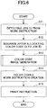
- FIG. 6 is a flowchart of an example of processing for creating a work instruction with a color code.
- the job ID detection unit 32 of the work process management system 14 detects the job ID displayed in the work instruction 800 for the customer system 10 by the bar code image 801 or the text.
- the detection frame for detecting the job ID from the work instruction 800 may be set in advance by the operator, or may be automatically set by using OCR or the like.
- step S12 the job management unit 34 selects the color code ID to be used from the color code management table memory unit 46, and manages the selected color code ID in association with the job ID detected by the job ID detection unit 32.
- step S13 the color code image generation unit 36 generates a color code image 811 from the color code ID associated with the job ID in the procedure illustrated in FIG. 7 .
- the procedure illustrated in FIG. 7 uses, for example, the technique described in Japanese Laid-Open Patent Application No. 2017-199306 .
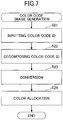
- FIG. 7 is a flowchart of an example of processing for generating a color code image.
- the color code image generation unit 36 receives an input of a color code ID to be color coded.
- the color code image generation unit 36 decomposes the character string of the color code ID into the values of the digits.
- the color code image generation unit 36 converts the value of each separated digit into a value corresponding to the number of colors to be assigned to each cell of the optical symbol described in Japanese Laid-Open Patent Application No. 2017-199306 . For example, if the number of colors assigned to each cell is four, the color code image generation unit 36 converts the value of each digit into a value of a ternary number according to a coding rule as illustrated in FIG. 8 , for example.
- FIG. 8 explains a coding rule capable of expressing a ternary number.
- FIG. 8 shows an example of the coding rule when four colors of red color (hereinafter, referred to as "R"), green color (hereinafter, referred to as “G”), blue color (hereinafter, referred to as “B”), and black color (hereinafter, referred to as "K”) are used.
- R red color
- G green color
- B blue color
- K black color
- each transition from R to K, from K to B, from B to G, and from G to R represents a value "0".
- each transition from R to G, G to B, B to K, and K to R in the counterclockwise direction represents a value "1".
- bi-directional transitions along the diagonals, i.e. between R and B, and between K and G, respectively, represent the value "2".
- the transition from G to R represents the value "0”
- the transition from R to B represents the value "2”
- the transition from B to K represents the value "1”
- the transition from K to G represents the value "2”.
- the array of FIG. 8B represents a value "3d2120", i.e. a decimal value "69”.
- the first "3d” in the notation of the values indicates that the next number is a three decimal value.
- the coding rule using the four color transition is not limited to the example illustrated in FIG. 8A , and may be, for example, the example illustrated in FIG. 8D.
- FIG. 8E shows an example of a conversion table associating color transitions and values according to the coding rule illustrated in FIG. 8D .
- the color of the cell of a transition destination adjacent to the cell of the transition source is set to B.
- the color of the cell of the transition destination is G.
- step S24 the color code image generation unit 36 assigns colors to the respective cells of the optical symbol in accordance with the color of the cell of the transition source, the value of the ternary number converted in step S23, and the conversion table of the coding rule as illustrated in FIG. 8A .
- the color code image generation unit 36 stores in advance the color arrangement of each cell in the cell string of the main code of the optical symbol.
- FIG. 9 is a diagram showing an example of information to be coded into the optical symbol.
- FIG. 10 is a diagram showing an example of the optical symbol in the case where the number of colors assigned to each cell of the optical symbol is four.
- FIG. 9 is an example of the values "3d1,” “3d1,” “3d0,” and “3d1” in each cell column of the sub-code unit 301 connected to "d1,” “d2,” “d3,” and "d4" of the main code unit 300.
- FIG. 10 shows an example of an optical symbol in which the information illustrated in FIG. 9 is coded according to the coding rule described with reference to FIGS. 8A to 8E .
- the cell row of the main code unit 300 includes an even number of cells, and is configured by alternately arranging K and R with the leading end cell as K.
- the color of the cell is assigned to the sub-code unit 301 by using K of the cell of the main code unit 300 to which the cell is connected as the color of the first transition source.
- R is assigned to the cell of the leftmost sub-code unit 301 of the optical symbols by referring to the translation table of the coding rules of FIG. 8A in accordance with K of the cell of the main code unit 300 which is the cell of the source of the transition and the value "3d1" of the cell of the sub-code unit 301.
- step S14 the color-coded work instruction creation unit 38 creates a work instruction 810 for the information processing system 12 using the color code image 811 generated in step S13.
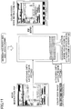
- FIG. 11 is a diagram showing an image of processing for creating a work instruction with color code.
- the paper size and the layout frame may be set in advance by the operator.
- the work instruction 800 for the customer system 10 of FIG. 2A is scaled down to create a free space.
- the work instruction 810 for the information processing system 12 illustrated in FIG. 2B is obtained by attaching a color code image 811 to an empty space generated by scaling down the work instruction 800 for the customer system 10.
- the color-coded work instruction creation unit 38 confirms the direction of the bar code image 801 in the procedure illustrated in FIG. 12 , and performs scaling and reduction in the direction in which the function of the bar code image 801 is not impaired.
- FIG. 12 is a flowchart of an example of processing for reducing an image including a bar code image.
- the color-coded work instruction creation unit 38 cuts out the position of the bar code image 801 of the work instruction 800 for the customer system 10 illustrated in FIG. 2A .
- the color-coded work instruction creation unit 38 determines whether the extracted bar code image as illustrated in FIG. 13 is a Bk (monochrome) image or an RGB (RGB) image.
- FIG. 13 illustrates an example of a bar code image.
- step S33 converts the RGB image into a Lab image or a Luv image, creates a monochrome image in which only the L component is extracted after the conversion, and proceeds to step S34. If the image is a monochrome image, the color-coded work instruction creation unit 38 skips step S33 and proceeds to step S34.
- step S34 the color-coded work instruction creation unit 38 raster scans all the pixels in the bar code image of FIG. 13 .
- the pixel position (x, y) is a position according to the X direction and the Y direction displayed in FIG. 13 .
- the color-coded work instruction creation unit 38 integrates the values of the pixels having the same pixel position x, that is, the values of the pixels in the Y direction.
- step S35 the color-coded work instruction creation unit 38 integrates all the pixels.
- the color-coded work instruction creation unit 38 obtains an average value by dividing the value obtained by integrating all the pixels by the number of all the pixels.
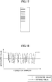
- step S36 the color-coded work instruction creation unit 38 confirms the number of changes by comparing the integrated value of the pixels having the same pixel position x obtained in step S34 with the average value obtained in step S35.
- FIG. 18 is an explanatory diagram of an example of the number-of-changes checking process.
- the work instruction creation unit 38 with color code confirms the number of times of change obtained by totaling the number of times of change from the integrated value high than the average value to the integrated value lower than the average value and the number of times of change from the integrated value lower than the average value to the integrated value higher than the average value.
- step S37 the color-coded work instruction creation unit 38 determines whether or not the number of changes confirmed in step S36 is 24 or more. If the number of changes is 24 or more, the process advances to step S38, and the color-coded work instruction creation unit 38 performs scaling in a direction in which the bar code image of FIG. 14 is reduced in the vertical direction as in the bar code image of FIG. 15 , for example.
- FIG. 14 illustrates an example of a bar code image before reduction in the vertical direction.
- FIG. 15 illustrates an example of a bar code image after being reduced in the vertical direction.
- the step S39 proceeds, and the work instruction creation unit 38 with a color code reduces the bar code image shown in FIG. 16 in a direction that is reduced in a lateral direction, such as the bar code image shown in FIG. 17 .
- the process of the flowchart of FIG. 12 determines the direction of the bar code image based on the following idea. For example, in the case of a vertical bar code as illustrated in FIG. 13 , since there is the width of a black line, a change from a white line to a black line and a change from the black line to the white line occur in a set. The number of changes varies according to the number of displayed digits of the bar code, but when a typical bar code is examined, if the number of changes is 24 or more, it can be determined that the bar code is a vertical bar code as illustrated in FIG. 13 .
- step S36 the color-coded work instruction creation unit 38 confirms the number of changes as illustrated in FIG. 20.
- FIG. 19 illustrates an example of a bar code image.
- FIG. 20 explains an example of a process of checking the number of changes.
- the number of times of change obtained by totaling the number of times of change from the integrated value higher than the average value to the integrated value lower than the average value and the number of times of change from the integrated value lower than the average value to the integrated value higher than the average value is extremely small, even if information other than the bar code image is integrated, the number of times of change does not become 24 or more, for example. Therefore, if the number of changes is 24 or more, it can be determined that there presents a bar code in the lateral direction as illustrated in FIG. 19 .
- the direction of the bar code image can be determined by Fourier transform, Hough transform which is one of feature extraction methods, or the like.
- Hough transform which is one of feature extraction methods, or the like.
- recent printers perform halftone processing.
- an all-wire dither may be used.
- the work process management system 14 of the present embodiment it is possible to create an empty space by scaling in a direction that does not impair the function of the bar code image 801, and to add the color code image 811 that can be read remotely to the empty space. Even if the work instruction 800 for the customer system 10 is scaled down, the function of the bar code image 801 is not impaired, and the function of the color code image 811 can be added to the work instruction 810 for the information processing system 12 while the function of the work instruction 800 for the customer system 10 remains.
- step S15 the print instruction unit 40 instructs the printer 16 to print the work instruction 810 for the information processing system 12 to which the color code image 811 created in step S14 is added.
- the printer 16 prints a work instruction 810 for the information processing system 12 to which a color code image 811 as illustrated in FIG. 2B , for example, is added in accordance with an instruction from the print instruction unit 40.
- the job status of the job management table memory unit 48 is updated as follows by photographing the work instruction 810 for the information processing system 12 to which the color code image 811 is added by the camera 18a.
- FIG. 21 is a flowchart of an example of job status update processing when a gate is passed.
- step S52 the color code recognition unit 44 tries to cut out the color code image 811 from the photographed image or the photographed moving image acquired by the photographed image acquisition unit 42.
- step S 53 the color code recognition unit 44 performs recognition processing of the color code image 811 in the procedure described in, for example, Japanese Patent Laid-Open Patent Application No. 2017-199306 .
- the color code recognition unit 44 detects an image of each cell from the color code image 811.
- the color code recognition unit 44 recognizes the color information of each cell detected in step S53 and the connection information of each cell as symbol information.
- the color code recognition unit 44 proceeds to step S54, and decodes the symbol information according to the coding rule illustrated in FIG. 8A , for example, to restore the color code ID coded in the color code image 811.
- step S55 the color code recognition unit 44 provides, for example, identification information of the camera 18a that photographed the color code image 811 and the color code ID restored by decoding to the job management unit 34.
- the job management unit 34 refers to the job management table memory unit 48 and identifies the job ID corresponding to the color code ID.
- the job management unit 34 can update the job status managed in the job management table memory unit 48 from "undetected” to "current process” or “passed” based on, for example, the identification information of the camera 18a that photographed the color code image 811 and the job ID corresponding to the color code ID restored from the color code image 811.
- the job status of the job management table memory unit 48 is updated as follows by photographing the work instruction 810 for the information processing system 12 to which the color code image 811 is added by the camera 18b.
- FIG. 22 is a flowchart of an example of job status update processing at the time of storage in a temporary storage location.
- step S62 the color code recognition unit 44 tries to cut out the color code image 811 from the photographed image or the photographed moving image acquired by the photographed image acquisition unit 42.
- step S63 the color code recognition unit 44 performs recognition processing of the color code image 811 in the procedure described in, for example, Japanese Laid-Open Patent Application No. 2017-199306 .
- step S63 If the color code image 811 is recognized in step S63, the color code recognition unit 44 proceeds from step S64 to step S65, and decodes the symbol information recognized from the color code image 811 to restore the color code ID encoded in the color code image 811.
- step S66 the color code recognition unit 44 provides, for example, identification information of the camera 18b that photographed the color code image 811 and the color code ID restored by decoding to the job management unit 34.
- the job management unit 34 refers to the job management table memory unit 48 and identifies the job ID corresponding to the color code ID.
- the job management unit 34 determines whether a predetermined time has elapsed without a change in the job status of the job ID based on, for example, the identification information of the camera 18b that photographed the color code image 811 and the job ID corresponding to the color code ID restored from the color code image 811.
- step S70 the job management unit 34 can update the job status managed by the job management table memory unit 48 from "undetected" to "current process".
- the job management unit 34 performs the processing to display the residence alert on the job detail history screen described later, and then proceeds to the processing of step S70.
- step S70 the job management unit 34 can update the job status managed by the job management table memory unit 48 from the "current process” to the "alert” or the like.
- step S70 If the predetermined period of time has elapsed without any change in the job status, the job management unit 34 performs a process for displaying a stay alert on a job detail history screen, which will be described later, and then proceeds to the process of step S70. If the predetermined time has not elapsed without any change in the job status, the job management unit 34 proceeds to step S70.
- step S70 the job management unit 34 can update the job status managed by the job management table memory unit 48 from "undetected" to "current process”.
- step S63 the color code recognition unit 44 proceeds from step S64 to step S68, and if the color code image 811 cannot be recognized from the photographed image from the camera 18b installed in the temporary storage location, processing is performed to update the job ID that the job status is to be stored in the temporary storage location.
- the color code recognition unit 44 provides, for example, identification information of the camera 18b to the job management unit 34.
- the job management unit 34 determines whether or not there is a job ID for which the color code image 811 has not been recognized from the photographed image continuously for a predetermined number of times, among job IDs for which the job status of the temporary storage location corresponding to the provided identification information of the camera 18b is "current process".
- step S69 the job management unit 34 can update the job status managed by the job management table memory unit 48 from the "current process” to the "passed” or the like.
- the work instruction 810 for the information processing system 12 is stored in a state in which it is impossible to take a picture from the camera 18b, for example, the printed matter is superimposed on the temporary storage location.
- step S69 the job management unit 34 skips step S69 and proceeds to step S70 if there is no job ID whose color code image 811 has not been recognized from the photographed image consecutively for a predetermined number of times among the job IDs whose job status of the temporary storage location is "current process".
- step S70 the job management unit 34 can update the job status managed by the job management table memory unit 48 from the "current process” to the "stack".
- the operator of the job management system 1 can inquire the progress information and the history information of the work process of the job in the printing factory, the photographed image file representing the state when the work instruction 810 is photographed, the photographed moving image file, and the like through various UI screens provided by the work process management system 14.
- FIG. 23 is a transition diagram of an example of a UI screen displayed by the work process management system.
- the UI unit 30 of the work process management system 14 displays, for example, a job status list screen 1000 on the display device 502.
- the job status list screen 1000 displays a list of job information including a job ID, a color code ID, a job name, last update data, and progress information of one or more work processes.
- the progress information of one or more work processes indicates whether the work process progress is "undetected”, “passed”, “current process”, “alert” or "stacked".
- the progress "undetected" of the work process indicates that the work instruction 810 for the information processing system 12 is not photographed by the camera 18 corresponding to the work process.
- the progress "passed" of the work process indicates that the work instruction 810 for the information processing system 12 has been photographed by the camera 18 corresponding to the work process before the last update.
- the progress "current process" of the work process indicates that the work instruction 810 for the information processing system 12 has been photographed by the camera 18 corresponding to the work process in the final update.
- the progress "alert" of the work process indicates that an alert such as, for example, a stay alert has occurred.
- the progress "stacking" of the work process indicates that the camera 18 corresponding to the work process has taken the work instruction 810 for the information processing system 12 before the last update and that the camera 18 corresponding to the work process and other work processes has not taken the work instruction 810 for the information processing system 12 with the last update.
- the "stacking" of the progress of the work process indicates a condition in which it is anticipated that the printed matter to which the work instruction 810 is affixed could not be photographed with the camera 18 due to stacking or the like.
- the key mark 1002 of the job status list screen 1000 indicates that the color code ID associated with, for example, a long-term storage job is locked so as not to be automatically released.
- the process management system 14 provides the operator with a locking function in which the color code ID is not reused.
- the operator can display the job detail history screen 1010 by selecting one job from the job status list screen 1000.
- the job detail history screen 1010 displays buttons for shifting to a screen for displaying a start date and time, a completion date and time, and a photographed image or a photographed moving image for each work process.
- job detail history screen 1010 displays a "traffic line display” button for transitioning to the traffic line display screen 1050, which will be described later.
- the UI unit 30 shifts to the screen 1020 for displaying the photographed image or the photographed moving image.
- the photographed image file or the photographed moving image file representing the state of photographing the work instruction 810 is displayed.
- FIG. 26 illustrates an example of the map display screen of the temporary storage location.
- the UI unit 30 causes the map display screen 1030 to display, for example, a photographed image of a temporary storage location on the background, and also causes the map display screen 1030 to display the image so that the storage area in which the printed matter is stored can be identified by the mark " ⁇ " or the like.
- the job status list screen 1000 of FIG. 23 may be displayed by performing grouping as illustrated in FIG. 24 , or may be configured to accept designation of a search condition as illustrated in FIG. 25 .
- FIGS. 24A to 24C are explanatory diagrams illustrating an example of a grouping process in a UI screen.
- FIG. 24A illustrates an example of the job status list screen 1000 before the grouping process.
- FIGS. 24B and 24C are examples in which progress information of one or more work processes of the job status list screen 1000 after the grouping process is grouped for each of the "first floor area" and the "second floor area” to facilitate visual grasp.
- the grouped "first floor area” is displayed in a folded manner.
- the progress information and (logical conjunction/AND) of the work process included in the group are displayed as the progress information of the group so that the progress information of the work process included in the folded "1st floor area” group is understood.
- the progress information and of the work process included in the group is determined as "alert > current process > stacked > passed > undetected".
- FIGS. 25A to 25C explain examples of the search condition specifying process on the UI screen.
- FIGS. 25A to 25C illustrate examples of a job status list screen 1000 in which a search line is provided. The search line is displayed, for example, by pressing the "search" button on the job status list screen 1000.
- the operator can search for a job that matches the search condition by specifying the search condition in the search line.
- the search lines provided as in FIGS. 25A-25C have the effect of improving immediacy and visibility due to the small screen transitions.
- FIG. 25A illustrates an example in which a search condition is entered in the search line with a text item (partial matching).
- FIG. 25B illustrates an example of inputting a search condition in a time and date and time item (specified range) on the search line.
- FIG. 25C illustrates an example in which the search condition is selected by pull-down in the search line in the work process item (matching).
- Selection by pull-down may be made, for example, to allow multiple selection by the control key.
- the "condition clear" button is pressed, all search conditions are cleared and all items are displayed.
- the progress information of one or more work processes of the job status list screen 1000 may be represented by a marker, for example, as shown in FIG. 27 .
- the color of the marker is represented by a kanji character.
- the time has elapsed in the order of (a) to (e) in FIG. 27 .
- the second work process in (c) which was the progress "current process,” is the progress "accumulated” in (d).
- the progress information of the one or more work processes shown in (d) of FIG. 27 is again photographed by the camera 18 in a work instruction 810 for the information processing system 12, resulting in any of the conditions shown on the right side of FIG. 27 .
- the operator can also display the dashboard display screen 1040 by pressing the "dashboard" button on the job status list screen 1000.
- FIG. 28 is an explanatory diagram illustrating an example of a switching between a job status list screen and a dashboard display screen.
- dashboard display screen 1040 takes over the search condition specification and displays it.
- the operator can also display the job status list screen 1000 by pressing the "return to list” button on the dashboard display screen 1040.
- the job status list screen 1000 may take over the original search condition specification before the transition to the dashboard display screen 1040.
- FIG. 29 is an image diagram illustrating an example of a dashboard display screen.
- the dashboard display screen 1040 displays information about the progress of multiple jobs by a marker (an example of a display object) representing the location on the map of the job and the number of jobs per location.
- a marker an example of a display object representing the location on the map of the job and the number of jobs per location.
- FIG. 29 shows the number of jobs and alerts in the process category for each of "process category A", "process category B", and "process category C”.
- the dashboard display screen 1040 of FIG. 29 may enclose the process category in a frame and embed the factory map as a background image.
- the position where the marker is displayed indicates one or more work processes.
- the size of the marker indicates the number of jobs in the process.
- This feature distinguishes between the colors of normal markers (e.g., green) that do not contain the job where the alert occurred and the colors of alert markers (e.g., red) that contain the job where the alert occurred.
- FIG. 30 is an illustrative view of an example of a marker.
- the marker in FIG. 30 is an example represented by a bubble (circle mark) and is represented by a circle of five level sizes corresponding to the number of jobs for a specified work process.
- the parameters of the marker in FIG. 30 include a range of job numbers, a central coordinate, a radius (size) and a color (normal marker/alert marker). Normal marker colors may vary from one level to another.
- the dashboard display screen 1040 provides a visually understandable display of the number of jobs in each work process and the work process that includes the job where the alert is occurring.
- the traffic line display screen 1050 can be displayed when the operator presses a "traffic line” button on the job detail history screen 1010.
- FIG. 31 is an image diagram illustrating an example of a traffic line display screen.
- the traffic line display screen 1050 displays the traffic line by connecting the job history with a curve on the map based on the information about the job history displayed on the job detail history screen 1010.
- the curve is, for example, a Bezier curve.
- the Bezier curve is an (N-1)th order curve obtained from control points as many as N.
- the line display screen 1050 of FIG. 31 illustrates the points of the work process in circles. Circles are displayed by specifying the center coordinate, radius, color, and transparency. The work process that the job has not passed is hidden.
- the center coordinate of the work process through which the job has passed is connected by a Bezier curve so that the traffic line of the job can be visually represented.
- a mouse may be brought over the circle so as to display information such as the process name/transit time (all if any) of the work process corresponding to the circle.
- the progress information of the work process of the job in the printing factory can be checked in the list.
- the work process management system 14 of the present embodiment it is possible to confirm the history information of the work process of the job in the printing factory, the photographed image file representing the state when the work instruction 810 is photographed, the photographed moving image file, and the like by a simple operation.
- the work process management system 14 creates the work instruction 810 for the information processing system 12.
- the customer system 10 creates the work instruction 810 for the information processing system 12.
- the second embodiment is the same as the first embodiment except for a part thereof. Therefore, descriptions of the same parts as those of the first embodiment are appropriately omitted.
- FIG. 32 is a functional configuration diagram of another example of the work process management system.
- a work process management system 14a illustrated in FIG. 32 is configured by excluding the color-coded work instruction creation unit 38 and the print instruction unit 40 from the work process management system 14 illustrated in FIG. 4 .
- a customer system 10a has a color-coded work instruction creation unit 60 and a print instruction unit 62 added thereto.
- the generation of the color code image 811 is performed by a work process management system 14a in the same manner as in the first embodiment, and steps S14 and S15 of FIG. 6 are performed by the color-coded work instruction creation unit 60 and the print instruction unit 62 of the customer system 10.
- the first and second embodiments described above are techniques realized by the work instruction 810 for the information processing system 12 in which a new code (color code image 811) is added to the work instruction 800 for the customer system 10.
- This technique can be applied to, for example, a technique of a conveyance system represented by an AGV (unmanned conveyance vehicle).
- the work instruction 810 for the information processing system 12 to which a color code image 811 is added is attached, and the image of an article being conveyed is photographed by the camera 18, so that the work process of the article being conveyed by the conveyance device can be managed.
- the conveyance system can also control the movement of the conveyance device that conveys the article.
- first and second embodiments have been described with respect to the management of the work process of the job in the printing factory, the present embodiment can be applied to the management of the work process of the article flowing on the belt conveyor, for example.
- the technique of the present embodiment is provided for the management of the working process of the goods flowing on the belt conveyor, the tracking of the articles flowing on the belt conveyor becomes possible, and the branching of the belt conveyor can be controlled.
- the job ID is an example of the first identification information described in the claims.
- the color code image is an example of the second identification information.
- the job ID detection unit 32 is an example of a detection unit.
- the color code image generation unit 36 is an example of a generating unit.
- the color-coded work instruction creation unit 38 is an example of a creation unit.
- the job management unit 34 is an example of a management unit.
- the camera 18 is an example of a photographing unit.
- the color code recognition unit 44 is an example of a recognition unit.
- the work instruction 800 for the customer system 10 is an example of a first slip image as claimed.
- the work instruction 810 for the information processing system 12 is an example of a second slip image.
- the bar code image 801 is an example of a code image displayed on the first slip image.
- the color code image 811 is an example of a new code image.
- the color-coded work instruction creation unit 38 for checking the direction of the bar code image 801 illustrated in FIG. 12 is an example of a determination unit.
- the color-coded work instruction creation unit 38 that performs scaling and reduction in a direction that does not impair the function of the bar code image 801 illustrated in FIG. 12 is an example of a reduction unit.
- the color-coded work instruction creation unit 38 that creates the work instruction 810 for the information processing system 12 by using the generated color code image 811 is an example of a creating unit.
- the color code image generation unit 36 is an example of a generating unit.
- the present invention is not limited to the embodiments specifically disclosed above, and various modifications and variations are possible without departing from the scope of the claims.
- the color code image 811 is an example of a code image associated with the job described in the claims.
- the work instruction 810 for the information processing system is an example of a slip.
- the camera 18 is an example of a photographing unit.
- the color code recognition unit 44 is an example of a recognition unit.
- the job management unit 34 is an example of a management unit.
- the UI unit 30 is an example of providing unit.
- the photographed image file and the photographed moving image file are examples of photographing data.
- the job status list screen 1000 is an example of a list screen.
- the job detail history screen 1010 is an example of a detail screen.
- a function realized by a slip can be easily added.
- the code image displayed on the first slip image can be reduced in a readable state, and a second slip image on which a new code image is displayed can be created.
- an information processing system in which a user can easily confirm information on the progress of a plurality of jobs composed of a plurality of work processes.
Landscapes
- Engineering & Computer Science (AREA)
- Physics & Mathematics (AREA)
- Theoretical Computer Science (AREA)
- General Physics & Mathematics (AREA)
- Business, Economics & Management (AREA)
- Human Resources & Organizations (AREA)
- Health & Medical Sciences (AREA)
- General Health & Medical Sciences (AREA)
- Computer Vision & Pattern Recognition (AREA)
- Artificial Intelligence (AREA)
- Toxicology (AREA)
- Electromagnetism (AREA)
- Economics (AREA)
- General Engineering & Computer Science (AREA)
- Strategic Management (AREA)
- Human Computer Interaction (AREA)
- Entrepreneurship & Innovation (AREA)
- Tourism & Hospitality (AREA)
- General Business, Economics & Management (AREA)
- Marketing (AREA)
- Educational Administration (AREA)
- Operations Research (AREA)
- Development Economics (AREA)
- Game Theory and Decision Science (AREA)
- Quality & Reliability (AREA)
- Manufacturing & Machinery (AREA)
- Primary Health Care (AREA)
- General Factory Administration (AREA)
- Management, Administration, Business Operations System, And Electronic Commerce (AREA)
- Medical Treatment And Welfare Office Work (AREA)
- Image Processing (AREA)
Applications Claiming Priority (4)
| Application Number | Priority Date | Filing Date | Title |
|---|---|---|---|
| JP2018142991A JP7200526B2 (ja) | 2018-07-30 | 2018-07-30 | 情報処理システム、情報処理方法、プログラム及び媒体 |
| JP2018142989 | 2018-07-30 | ||
| JP2018142990A JP7070207B2 (ja) | 2018-07-30 | 2018-07-30 | 情報処理システム、情報処理方法、プログラム及び媒体 |
| JP2019049124A JP7358756B2 (ja) | 2018-07-30 | 2019-03-15 | 情報処理システム、進捗管理方法及びプログラム |
Publications (2)
| Publication Number | Publication Date |
|---|---|
| EP3605308A2 true EP3605308A2 (de) | 2020-02-05 |
| EP3605308A3 EP3605308A3 (de) | 2020-03-25 |
Family
ID=67437672
Family Applications (1)
| Application Number | Title | Priority Date | Filing Date |
|---|---|---|---|
| EP19185776.2A Ceased EP3605308A3 (de) | 2018-07-30 | 2019-07-11 | Informationsverarbeitungssystem zur erstellung von belegen |
Country Status (3)
| Country | Link |
|---|---|
| US (4) | US11023699B2 (de) |
| EP (1) | EP3605308A3 (de) |
| CN (2) | CN110781991B (de) |
Cited By (3)
| Publication number | Priority date | Publication date | Assignee | Title |
|---|---|---|---|---|
| EP3709152A1 (de) * | 2019-03-15 | 2020-09-16 | Ricoh Company, Ltd. | Informationsverarbeitungssystem |
| EP3882728A1 (de) * | 2020-03-17 | 2021-09-22 | Ricoh Company, Ltd. | Informationsverarbeitungssystem, informationsverarbeitungsverfahren, speichermedium und informationsverarbeitungsvorrichtung |
| EP3882760A1 (de) * | 2020-03-17 | 2021-09-22 | Ricoh Company, Ltd. | Informationsverarbeitungssystem, informationsverarbeitungsverfahren und informationsverarbeitungsvorrichtung |
Families Citing this family (7)
| Publication number | Priority date | Publication date | Assignee | Title |
|---|---|---|---|---|
| EP3605308A3 (de) * | 2018-07-30 | 2020-03-25 | Ricoh Company, Ltd. | Informationsverarbeitungssystem zur erstellung von belegen |
| WO2020170963A1 (ja) * | 2019-02-20 | 2020-08-27 | 日本電気株式会社 | 処理装置、処理方法及びプログラム |
| US20230196840A1 (en) * | 2020-03-24 | 2023-06-22 | Sony Group Corporation | Work management device and work state determination method |
| JP7639432B2 (ja) | 2021-03-19 | 2025-03-05 | 株式会社リコー | 情報処理システム、位置管理方法、情報処理装置及びプログラム |
| JP7643118B2 (ja) | 2021-03-19 | 2025-03-11 | 株式会社リコー | 情報処理システム、位置管理方法、情報処理装置及びプログラム |
| JP2023140699A (ja) * | 2022-03-23 | 2023-10-05 | 株式会社リコー | 情報処理システム、情報処理方法、プログラム及び情報処理装置 |
| JP2024035440A (ja) * | 2022-09-02 | 2024-03-14 | 株式会社リコー | 情報処理システム、管理方法、情報処理装置及びプログラム |
Citations (4)
| Publication number | Priority date | Publication date | Assignee | Title |
|---|---|---|---|---|
| JP2005100298A (ja) | 2003-09-12 | 2005-04-14 | Jebiz International:Kk | Rfidを用いたスループット最大化システム |
| JP2010012667A (ja) * | 2008-07-02 | 2010-01-21 | Seiko Epson Corp | 印刷装置、印刷装置の制御方法および印刷制御プログラム |
| JP2014042148A (ja) | 2012-08-22 | 2014-03-06 | Canon Inc | 画像形成装置及び方法、並びにプログラム |
| JP2017199306A (ja) | 2016-04-28 | 2017-11-02 | 株式会社リコー | 光学シンボル、表示媒体、物品および生成装置 |
Family Cites Families (28)
| Publication number | Priority date | Publication date | Assignee | Title |
|---|---|---|---|---|
| JP3440317B2 (ja) | 1997-09-17 | 2003-08-25 | 富士通株式会社 | テーブル登録機能付サブシステム、分散システム、及び記録媒体 |
| JPH11109602A (ja) | 1997-10-03 | 1999-04-23 | Dainippon Screen Mfg Co Ltd | 作業管理システムおよびその方法、並びに、その管理を実行するためのプログラムを記録した記録媒体 |
| JP2002137812A (ja) | 2000-11-02 | 2002-05-14 | Hosnet Japan:Kk | 物品の管理システムを含む総合管理方法 |
| US7206997B2 (en) * | 2000-12-18 | 2007-04-17 | General Motors Corporation | Functional visualization of spreadsheets |
| JP2006259045A (ja) | 2005-03-16 | 2006-09-28 | Fuji Xerox Co Ltd | 画像形成装置及び方法 |
| JP4991154B2 (ja) * | 2005-06-03 | 2012-08-01 | 株式会社リコー | 画像表示装置、画像表示方法及びコマンド入力方法 |
| JP4330590B2 (ja) | 2006-02-22 | 2009-09-16 | 広行 遠藤 | データ提供システム,サーバおよびプログラム |
| JP2007249658A (ja) | 2006-03-16 | 2007-09-27 | Sony Corp | 製品生成端末装置、製品生成方法、プログラム |
| JP2007328399A (ja) | 2006-06-06 | 2007-12-20 | Konica Minolta Holdings Inc | バーコード画像生成装置、及びバーコード画像生成方法 |
| WO2008010513A1 (en) * | 2006-07-19 | 2008-01-24 | B-Core Inc. | Optical symbol, article to which the optical symbol is attached, method for attaching optical symbol to article, optical symbol decoding method, related device, and related program |
| JP2008059322A (ja) | 2006-08-31 | 2008-03-13 | Sharp Corp | 作業管理システム |
| JP5117060B2 (ja) * | 2006-09-15 | 2013-01-09 | 株式会社シーネット | 物品の出入管理システム |
| JP2009025851A (ja) * | 2007-07-17 | 2009-02-05 | Fujitsu Ltd | 作業管理装置及び作業管理方法 |
| JP5164663B2 (ja) * | 2008-05-09 | 2013-03-21 | キヤノン株式会社 | 印刷ジョブ管理装置、印刷ジョブ管理方法、及びコンピュータプログラム |
| JP5247743B2 (ja) | 2010-03-05 | 2013-07-24 | 中国電力株式会社 | 動線調査支援システム |
| JP5609301B2 (ja) | 2010-06-18 | 2014-10-22 | 大日本印刷株式会社 | 製造工程管理システム |
| US10068262B1 (en) * | 2010-12-23 | 2018-09-04 | Amazon Technologies, Inc. | Application for transaction information delivery |
| US8786883B2 (en) * | 2011-06-14 | 2014-07-22 | Hewlett-Packard Development Company, L.P. | Devices and methods for print job tracking using assignable mobile devices |
| EP2755096A4 (de) * | 2011-09-05 | 2014-12-31 | Kobayashi Manufacture Co Ltd | Arbeitsverwaltungssystem, arbeitsverwaltung endvorrichtung, programm und arbeitsverwaltung verfahren |
| JP5929505B2 (ja) * | 2012-05-23 | 2016-06-08 | 富士ゼロックス株式会社 | 情報処理装置及び情報処理プログラム |
| US20130346138A1 (en) * | 2012-06-26 | 2013-12-26 | Xerox Corporation | Creation of production process workflow diagrams |
| WO2015015594A1 (ja) | 2013-07-31 | 2015-02-05 | 株式会社日立システムズ | 管理対象物管理システム |
| JP6448187B2 (ja) | 2013-12-14 | 2019-01-09 | 三菱重工業株式会社 | 工程管理装置、工程管理プログラムおよび工程管理システム |
| JP2015225630A (ja) | 2014-05-30 | 2015-12-14 | パナソニックIpマネジメント株式会社 | 作業管理装置、作業管理システムおよび作業管理方法 |
| JP6558165B2 (ja) * | 2015-09-14 | 2019-08-14 | 株式会社リコー | 情報処理装置、情報処理方法およびプログラム |
| JP6634952B2 (ja) | 2016-04-28 | 2020-01-22 | 株式会社リコー | 認識装置、認識方法および認識プログラム、ならびに、管理システムおよび搬送システム |
| US10353647B2 (en) * | 2016-08-12 | 2019-07-16 | Canon Kabushiki Kaisha | Printing control apparatus, printing control method, and storage medium |
| EP3605308A3 (de) * | 2018-07-30 | 2020-03-25 | Ricoh Company, Ltd. | Informationsverarbeitungssystem zur erstellung von belegen |
-
2019
- 2019-07-11 EP EP19185776.2A patent/EP3605308A3/de not_active Ceased
- 2019-07-23 US US16/519,165 patent/US11023699B2/en active Active
- 2019-07-26 CN CN201910683804.9A patent/CN110781991B/zh active Active
- 2019-07-26 CN CN202410246487.5A patent/CN118052243A/zh active Pending
-
2021
- 2021-04-21 US US17/236,152 patent/US11714981B2/en active Active
-
2023
- 2023-06-06 US US18/329,812 patent/US12260293B2/en active Active
-
2025
- 2025-02-20 US US19/058,889 patent/US20250200313A1/en active Pending
Patent Citations (4)
| Publication number | Priority date | Publication date | Assignee | Title |
|---|---|---|---|---|
| JP2005100298A (ja) | 2003-09-12 | 2005-04-14 | Jebiz International:Kk | Rfidを用いたスループット最大化システム |
| JP2010012667A (ja) * | 2008-07-02 | 2010-01-21 | Seiko Epson Corp | 印刷装置、印刷装置の制御方法および印刷制御プログラム |
| JP2014042148A (ja) | 2012-08-22 | 2014-03-06 | Canon Inc | 画像形成装置及び方法、並びにプログラム |
| JP2017199306A (ja) | 2016-04-28 | 2017-11-02 | 株式会社リコー | 光学シンボル、表示媒体、物品および生成装置 |
Cited By (3)
| Publication number | Priority date | Publication date | Assignee | Title |
|---|---|---|---|---|
| EP3709152A1 (de) * | 2019-03-15 | 2020-09-16 | Ricoh Company, Ltd. | Informationsverarbeitungssystem |
| EP3882728A1 (de) * | 2020-03-17 | 2021-09-22 | Ricoh Company, Ltd. | Informationsverarbeitungssystem, informationsverarbeitungsverfahren, speichermedium und informationsverarbeitungsvorrichtung |
| EP3882760A1 (de) * | 2020-03-17 | 2021-09-22 | Ricoh Company, Ltd. | Informationsverarbeitungssystem, informationsverarbeitungsverfahren und informationsverarbeitungsvorrichtung |
Also Published As
| Publication number | Publication date |
|---|---|
| US20200034592A1 (en) | 2020-01-30 |
| US11023699B2 (en) | 2021-06-01 |
| US20250200313A1 (en) | 2025-06-19 |
| CN110781991A (zh) | 2020-02-11 |
| CN110781991B (zh) | 2024-03-22 |
| US12260293B2 (en) | 2025-03-25 |
| EP3605308A3 (de) | 2020-03-25 |
| CN118052243A (zh) | 2024-05-17 |
| US20230316024A1 (en) | 2023-10-05 |
| US20210240957A1 (en) | 2021-08-05 |
| US11714981B2 (en) | 2023-08-01 |
Similar Documents
| Publication | Publication Date | Title |
|---|---|---|
| US20250200313A1 (en) | Information processing system and slip creation method | |
| JP7200526B2 (ja) | 情報処理システム、情報処理方法、プログラム及び媒体 | |
| US11429321B2 (en) | Information processing system | |
| EP3882760B1 (de) | Informationsverarbeitungssystem, informationsverarbeitungsverfahren und informationsverarbeitungsvorrichtung | |
| JP7205507B2 (ja) | 情報処理システム | |
| JP7358756B2 (ja) | 情報処理システム、進捗管理方法及びプログラム | |
| EP3147810B1 (de) | Bildverarbeitungsvorrichtung und programm | |
| US11445084B2 (en) | Work process managing system to manage progress of a job including multiple work processes, work process managing method, and work process managing apparatus | |
| JP2021149945A (ja) | 情報処理システム、プログラム及び情報処理装置 | |
| JP7070207B2 (ja) | 情報処理システム、情報処理方法、プログラム及び媒体 | |
| CN115050038A (zh) | 信息处理装置、信息处理方法和存储介质 | |
| JP6880921B2 (ja) | 設定処理装置およびプログラム | |
| US8009926B2 (en) | Image processing apparatus, image processing method, and medium storing program | |
| JP7851273B2 (ja) | 情報処理システム、進捗管理方法、プログラム及び情報処理装置 | |
| KR100966783B1 (ko) | 정보처리장치, 정보처리장치의 제어방법, 및 기억매체 | |
| JP2024035440A (ja) | 情報処理システム、管理方法、情報処理装置及びプログラム | |
| US10168970B2 (en) | Print layout generating device, and non-transitory storage medium storing computer-readable instructions to generate print layout | |
| JP2006202197A (ja) | 画像管理システム |
Legal Events
| Date | Code | Title | Description |
|---|---|---|---|
| PUAI | Public reference made under article 153(3) epc to a published international application that has entered the european phase |
Free format text: ORIGINAL CODE: 0009012 |
|
| STAA | Information on the status of an ep patent application or granted ep patent |
Free format text: STATUS: REQUEST FOR EXAMINATION WAS MADE |
|
| 17P | Request for examination filed |
Effective date: 20190711 |
|
| AK | Designated contracting states |
Kind code of ref document: A2 Designated state(s): AL AT BE BG CH CY CZ DE DK EE ES FI FR GB GR HR HU IE IS IT LI LT LU LV MC MK MT NL NO PL PT RO RS SE SI SK SM TR |
|
| AX | Request for extension of the european patent |
Extension state: BA ME |
|
| REG | Reference to a national code |
Ref country code: DE Ref legal event code: R079 Free format text: PREVIOUS MAIN CLASS: G06F0003120000 Ipc: H04N0001387000 |
|
| PUAL | Search report despatched |
Free format text: ORIGINAL CODE: 0009013 |
|
| AK | Designated contracting states |
Kind code of ref document: A3 Designated state(s): AL AT BE BG CH CY CZ DE DK EE ES FI FR GB GR HR HU IE IS IT LI LT LU LV MC MK MT NL NO PL PT RO RS SE SI SK SM TR |
|
| AX | Request for extension of the european patent |
Extension state: BA ME |
|
| RIC1 | Information provided on ipc code assigned before grant |
Ipc: H04N 1/387 20060101AFI20200217BHEP Ipc: G06F 3/12 20060101ALI20200217BHEP Ipc: G05B 19/418 20060101ALI20200217BHEP Ipc: G06Q 10/06 20120101ALI20200217BHEP |
|
| STAA | Information on the status of an ep patent application or granted ep patent |
Free format text: STATUS: EXAMINATION IS IN PROGRESS |
|
| 17Q | First examination report despatched |
Effective date: 20210624 |
|
| STAA | Information on the status of an ep patent application or granted ep patent |
Free format text: STATUS: THE APPLICATION HAS BEEN REFUSED |
|
| 18R | Application refused |
Effective date: 20230715 |