EP3604918A1 - Ausstossrohr eines brenners, brenner und brennerkocher - Google Patents
Ausstossrohr eines brenners, brenner und brennerkocher Download PDFInfo
- Publication number
- EP3604918A1 EP3604918A1 EP18913472.9A EP18913472A EP3604918A1 EP 3604918 A1 EP3604918 A1 EP 3604918A1 EP 18913472 A EP18913472 A EP 18913472A EP 3604918 A1 EP3604918 A1 EP 3604918A1
- Authority
- EP
- European Patent Office
- Prior art keywords
- gas
- flame
- burner
- base
- cavity
- Prior art date
- Legal status (The legal status is an assumption and is not a legal conclusion. Google has not performed a legal analysis and makes no representation as to the accuracy of the status listed.)
- Pending
Links
Images


Classifications
-
- F—MECHANICAL ENGINEERING; LIGHTING; HEATING; WEAPONS; BLASTING
- F23—COMBUSTION APPARATUS; COMBUSTION PROCESSES
- F23D—BURNERS
- F23D14/00—Burners for combustion of a gas, e.g. of a gas stored under pressure as a liquid
- F23D14/26—Burners for combustion of a gas, e.g. of a gas stored under pressure as a liquid with provision for a retention flame
-
- F—MECHANICAL ENGINEERING; LIGHTING; HEATING; WEAPONS; BLASTING
- F23—COMBUSTION APPARATUS; COMBUSTION PROCESSES
- F23D—BURNERS
- F23D14/00—Burners for combustion of a gas, e.g. of a gas stored under pressure as a liquid
- F23D14/02—Premix gas burners, i.e. in which gaseous fuel is mixed with combustion air upstream of the combustion zone
- F23D14/04—Premix gas burners, i.e. in which gaseous fuel is mixed with combustion air upstream of the combustion zone induction type, e.g. Bunsen burner
- F23D14/06—Premix gas burners, i.e. in which gaseous fuel is mixed with combustion air upstream of the combustion zone induction type, e.g. Bunsen burner with radial outlets at the burner head
- F23D14/065—Premix gas burners, i.e. in which gaseous fuel is mixed with combustion air upstream of the combustion zone induction type, e.g. Bunsen burner with radial outlets at the burner head with injector axis inclined to the burner head axis
-
- F—MECHANICAL ENGINEERING; LIGHTING; HEATING; WEAPONS; BLASTING
- F23—COMBUSTION APPARATUS; COMBUSTION PROCESSES
- F23D—BURNERS
- F23D14/00—Burners for combustion of a gas, e.g. of a gas stored under pressure as a liquid
- F23D14/02—Premix gas burners, i.e. in which gaseous fuel is mixed with combustion air upstream of the combustion zone
- F23D14/04—Premix gas burners, i.e. in which gaseous fuel is mixed with combustion air upstream of the combustion zone induction type, e.g. Bunsen burner
- F23D14/08—Premix gas burners, i.e. in which gaseous fuel is mixed with combustion air upstream of the combustion zone induction type, e.g. Bunsen burner with axial outlets at the burner head
- F23D14/085—Premix gas burners, i.e. in which gaseous fuel is mixed with combustion air upstream of the combustion zone induction type, e.g. Bunsen burner with axial outlets at the burner head with injector axis inclined to the burner head axis
-
- F—MECHANICAL ENGINEERING; LIGHTING; HEATING; WEAPONS; BLASTING
- F23—COMBUSTION APPARATUS; COMBUSTION PROCESSES
- F23D—BURNERS
- F23D14/00—Burners for combustion of a gas, e.g. of a gas stored under pressure as a liquid
- F23D14/46—Details
- F23D14/62—Mixing devices; Mixing tubes
- F23D14/64—Mixing devices; Mixing tubes with injectors
-
- F—MECHANICAL ENGINEERING; LIGHTING; HEATING; WEAPONS; BLASTING
- F23—COMBUSTION APPARATUS; COMBUSTION PROCESSES
- F23D—BURNERS
- F23D23/00—Assemblies of two or more burners
-
- F—MECHANICAL ENGINEERING; LIGHTING; HEATING; WEAPONS; BLASTING
- F24—HEATING; RANGES; VENTILATING
- F24C—DOMESTIC STOVES OR RANGES ; DETAILS OF DOMESTIC STOVES OR RANGES, OF GENERAL APPLICATION
- F24C3/00—Stoves or ranges for gaseous fuels
- F24C3/08—Arrangement or mounting of burners
-
- F—MECHANICAL ENGINEERING; LIGHTING; HEATING; WEAPONS; BLASTING
- F23—COMBUSTION APPARATUS; COMBUSTION PROCESSES
- F23D—BURNERS
- F23D2900/00—Special features of, or arrangements for burners using fluid fuels or solid fuels suspended in a carrier gas
- F23D2900/14—Special features of gas burners
- F23D2900/14021—Premixing burners with swirling or vortices creating means for fuel or air
-
- F—MECHANICAL ENGINEERING; LIGHTING; HEATING; WEAPONS; BLASTING
- F23—COMBUSTION APPARATUS; COMBUSTION PROCESSES
- F23D—BURNERS
- F23D2900/00—Special features of, or arrangements for burners using fluid fuels or solid fuels suspended in a carrier gas
- F23D2900/14—Special features of gas burners
- F23D2900/14062—Special features of gas burners for cooking ranges having multiple flame rings
Definitions
- the present application mainly relates to the technical field of household appliances, in particular to a burner ejector, a burner using the burner ejector and a gas stove.
- Gas stove typically includes an ejector, the gas inflow end of which is connected to a nozzle base of the burner of the gas stove, and the gas outflow end of the ejector is connected to a flame distributor.
- the nozzle base is further connected to a gas inflow pipe. The gas enters the nozzle base from the gas inflow pipe, and is then ejected to the ejector through the nozzle of the nozzle base. After guided by the ejector, the gas enters the flame distributor and is ignited and combusted at the flame hole.
- each of the independent ejectors needs to be equipped with air ejecting holes, which complexes the structure and is also very likely to result in an insufficient air intake.
- the present application aims to provide a burner ejector, which mainly aims to remedy the defects of complex structure and insufficient air intake regarding the existed burner.
- the burner ejector provided by the present application includes a first base and a pipe body.
- a first end of the pipe body is communicated with the first base; a second end of the pipe body is provided with a second base configured to connect a flame distributor; the first base is configured to connect a nozzle base; an air ejecting hole is defined on the first base; the air ejecting hole and the nozzle base are arranged at an interval, allowing air to enter the pipe body from the air ejecting hole when gas is ejected from the nozzle base.
- the burner ejector includes a first cover body and a second cover body split from the first cover body. And the first base, the pipe body and the second base are formed by splicing the first cover body and the second cover body.
- a plurality of positioning pins are arranged at one of the first cover body and the second cover body, and positioning holes matched with the plurality of positioning pins are arranged at the other of the first cover body and the second cover body.
- the burner ejector includes one first base and a plurality of pipe bodies, and the plurality of pipe bodies extend along different radial directions of the first base.
- the burner ejector includes four pipe bodies, being respectively a first pipe body, a second pipe body, a third pipe body and a fourth pipe body and form an X-shape structure integrally.
- the air ejecting hole includes a plurality of long holes distributed along a radial direction of the first base.
- the present application further provides a burner including:
- the flame distributor includes a top surface and a bottom surface which are correspondingly arranged, in which, an outer peripheral surface is connecting the top surface and the bottom surface; a first cavity is defined in middle of the flame distributor passing through the top surface and the bottom surface; the outer peripheral surface and an inner wall of the first cavity defines the gas flaming cavity which includes an open end downward; a middle of the second base defines a second cavity running through the second base along an up-down direction, the gas mixing cavity is annularly and spacedly arranged at the periphery of the second cavity and the gas mixing cavity has an open end upward; the flame distributor is engaged with the second base, allowing the gas flaming cavity to be abutted and communicated with the gas mixing cavity, and allowing the first cavity and the second cavity to abut and form the through cavity.
- a guiding surface is arranged at an joint of a top surface and an inner wall of the first cavity, and the guiding surface tapers from top to bottom.
- a plurality of protrusions are spaced and arranged on the guiding surface along a circumferential direction, in which, each adjacent two of the plurality of protrusions defines a guiding groove; an inner flame hole is defined on the wall of the protrusions contacting the guiding groove and is communicated with the gas flaming cavity.
- annular flame spreading groove is defined at an joint of the top surface and the outer peripheral surface, and a plurality of middle flame holes are defined on an inner wall along a circumferential direction of the flame spreading groove and are communicated with the gas flaming cavity.
- an anti-block flange extending outwards is arranged on the top of the flame distributor corresponding to flame outlets of the plurality of middle flame holes, and the flame spreading groove is arranged between the anti-block flange and the flame outlets of the plurality of the middle flame holes.
- the outer peripheral surface includes a first peripheral surface, a second peripheral surface and a third peripheral surface.
- the first peripheral surface is a surface extending downward from the top surface and tapered from bottom to top;
- the second peripheral surface is a surface extending upward from the bottom surface and tapered from top to bottom;
- the third peripheral surface is a column surface extending up and down; an upper end of the third peripheral surface is connected to the first peripheral surface, and a lower end of the third peripheral surface is connected to the second peripheral surface.
- a plurality of outer flame holes are spaced and arranged on an inner wall of the gas flaming cavity corresponding to the third circumferential surface, and a plurality of flame stabilizing grooves, are defined on the third circumferential surface along a circumferential direction and communicated with the outer flame holes.
- At least one T-shaped flame stabilizing portion is arranged in the flame stabilizing groove.
- the nozzle base includes a base, on which two or more gas channels are arranged.
- the two or more gas channels are extended along different radial directions of the base; a first end of the two or more gas channels are configured to connect an air inflow pipe; a second end of the two or more of gas channels are configured to mount a nozzle and to eject gas to different burner ejectors.
- the base includes a mounting plate and a protruded block on the mounting plate, in which the mounting plate is configured to fix the burner nozzle base to the ejector, and the two or more gas channels are arranged in the protruded block.
- the gas channel includes a connecting portion communicated with a gas inflow hole and an accelerating portion, one end of which is communicated with the connecting portion, and the other end with a assembling hole of the nozzle base; an aperture of the accelerating portion is smaller than an aperture of the connecting portion.
- the present application also provides a gas stove, which includes:
- the burner is arranged above the panel and installed on the panel; or, the gas stove further includes a bottom casing positioned below the panel, and the burner is positioned below the panel and installed on the bottom casing.
- the gas stove further includes a temperature sensor;
- the pan support includes a first end to support a pot body and a second end opposite to the first end, in which the second end is extending towards the flame distributor and defines a stand vertically arranged in a through cavity; the stand defines an inner cavity which accommodates the temperature sensor.
- the burner ejector includes a first base and a pipe body, in which, a first end of the pipe body is communicated with the first base; a second end of the pipe body is provided with a second base configured to connect a flame distributor; the first base is configured to connect a nozzle base; an air ejecting hole is defined on the first base; the air ejecting hole and the nozzle base are arranged at an interval, allowing air to enter the pipe body from the air ejecting hole when gas is ejected from the nozzle base.
- the present application can centralize the gas supply, making air supplement favorable, can prevent insufficient combustion brought by insufficient air supply, thus the carbon monoxide content is reduced. In addition, the present application also improves the space efficiency.
- the terms “connected” and “fixed” etc. should be understood in a broad sense, otherwise specified and defined.
- “fixed” can be a fixed connection, a detachable connection, or an forming a part integrally; It can be a mechanical connection or an electrical connection; It can be a direct connection or an indirect connection through an intermediate medium; and it can be the communication between interior of two elements or the interaction between two elements, otherwise specifically defined.
- the specific meanings of the aforementioned terms in the present application can be understood according to practical conditions.
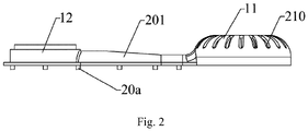
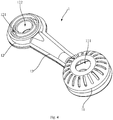
- the ejector 1 includes a first base 11 and a pipe body 13, in which the first end of the pipe body 13 is communicated with the first base 11, while the second end of the pipe body 13 is provided with a second base 12 which is configured to connect a flame distributor 2.
- the first base 11 is configured to connect a nozzle base (referring to Figs. 11 to 13 ), and the first base 11 is provided with an air ejecting hole 210 which is arranged at an interval with the nozzle base, allowing air to enter the pipe body 13 from the air ejecting hole 210 when gas is ejected from the nozzle base.
- the first base 11 is provided with an assembling hole 20 and an air ejecting hole 210.
- the assembling hole 20 is configured to connect the nozzle base.
- the assembling hole 20 and the air ejecting hole 210 are arranged at an interval. The gas ejected from the nozzle base will not leak from the air ejecting hole 210, because of the subatmospheric pressure.
- the ejector 1 may be formed integrally or separately, which is not limited thereto in the present application.
- the first base 11 of the ejector 1 is connected to the nozzle base, while the second base 12 of the ejector 1 is connected to the flame distributor 2, and the nozzle base is connected to the gas inflow pipe.
- the gas enters the nozzle base from the gas inflow pipe, followed by being ejected to the ejector 1 through the nozzle (not shown in the figure) of the nozzle base.
- the gas enters into the flame distributor 2 before being ignited and combusted near the flame hole.
- subatmospheric pressure is formed in the pipe body, allowing external air to enter the pipe body from the air ejecting hole, mixing with the gas.
- the present application can centralize the gas supply, making air supplement favorable and further preventing insufficient combustion brought by insufficient air supply. Thus the carbon monoxide content is reduced.
- the burner ejector 1 includes a plurality of cover bodies which can be spliced to form the first base 11, the pipe body 13 and the second base 12, which involves simple manufacturing processes and low cost.
- the cover bodies can be spliced and fixed in various possibilities.
- the burner ejector 1 includes a first cover body 201 and a second cover body 202 which two are arranged apart, and the first cover body 201 and the second cover body 202 are spliced to form the first base 11 and the pipe body 13.
- the number of cover bodies may be more than two, which should also be included in the technical solution of the present application.
- first cover body 201 and the second cover body 202 are superposed, and the first cover body 201 is positioned above the second cover body 202, which is, the burner ejector 1 in the present embodiment can be opened from one of the cover bodies.
- one of the first cover body 201 and the second cover body 202 is provided with a plurality of positioning pins 20a, and the other is provided with positioning holes 20b matched with the positioning pins 20a.
- the positioning pin 20a is arranged on the first cover body 201 (upper cover) and the positioning hole 20b on the second cover body 202 (lower cover).
- the positioning pin may also be arranged on the second cover body 202, and the corresponding positioning hole on the first cover body 201; or the first cover body 201 is provided with both of the positioning pins and positioning holes, so as the second cover body 202 is provided with positioning hole and positioning pin matched with the first cover body 201, all of which can realize the technical effect of the present application.
- the air has to be ensured tight, so as to avoid the leakage, after the engagement of the first cover body 201 and the second cover body 202.
- the burner ejector may includes one first bases 11 and more than one pipe bodies 13, as long as the technical effect of the present application can be realized by subatmospheric air intake.
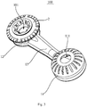
- the burner ejector may preferably includes one first bases 11 and a plurality of pipe bodies 13 which are extended toward different radial directions of the first bases 11. Since a plurality of pipe bodies 13 and a plurality of second base bodies 12 are connected through one first base 11, flaming at a plurality points can be implemented through centralized air supply, compacting the burner structure and improving the space efficiency.
- the burner ejector includes four pipe bodies, being respectively a first pipe body, a second pipe body, a third pipe body and a fourth pipe body and form an X-shape structure integrally.
- the whole burner may appear like an unmanned aerial vehicle, which is sensed aesthetically and technologically.
- the number of the pipe bodies 13 can be other such as three or five, which is not limited thereto in the present application.
- the ejector 1 can be arranged above the panel 200 of the gas stove or below the panel 200 of the gas stove. No matter which spatial layout is adopted, the ejector 1 of the present application can realize a full gas supply.
- the air ejecting hole 210 is arranged at the top of the first base 11, and the burner ejector 1 is mounted above the panel 200 of the gas stove.
- the air ejecting hole 210 is opened at the bottom of the first base 11, and the burner ejector 1 is mounted under the panel 200 of the gas stove.
- the present application may alternatively arrange the air ejecting hole 210 on the lateral side of the first base 11.
- Various designs in customer's favor would be chosen, as long as the space efficiency is enhanced and the entire structure is compact and beautified.
- the air ejecting hole 210 is arranged at a interval with the assembling hole 20 which is connected with the nozzle base. Further, the air should be taken in at a subatmospheric pressure.
- the shape of the air ejecting hole 210 is not limited in the present application.
- the air ejecting hole 210 includes a plurality of long holes distributed along the radial direction of the first base 11, which integrally forms an annular structure, so that air can be taken in from all directions to ensure a sufficient air supply for the ejector 1. The combustion efficiency has thus been enhanced, and manufacturing processes has also be simplified with a pleasant appearance.
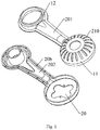
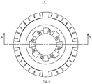
- the burner 100 includes a burner ejector 1 and a flame distributor 2.
- the ejector 1 includes a first base 11, a second base 12, and an ejector 13 connecting the first base 11 and the second base 12.
- a gas inflow cavity 111 is formed in the first base 11, and a gas mixing cavity 121 is formed in the second base 12.
- a gas guiding channel communicating the gas inflow cavity 111 and the gas mixing cavity 121 is formed in the ejector 13.
- the flame distributor 2 is covering on the top of the second base 12, and a gas flaming cavity 21 is formed in the flame distributor 2, communicated with the gas mixing cavity 121.
- the burner 100 further defines a through cavity 101, which is extended in a radical direction of the burner and run through the flame distributor 2 and the second base 12.
- the first base 11 is configured to communicate with an external gas pipeline and to provide gas.
- the second base 12 is configured to deliver the gas into the gas flaming cavity 21 of the flame distributor 2.
- a gas inflow cavity 111 is formed in the first base 11, a gas nozzle can be arranged in the gas inflow cavity 111 to communicate with the external gas pipeline, and the surface of the first base 11 is hollowed for introducing the air.
- the gas nozzle base delivers the gas to the gas mixing cavity 121 of the second base 12 via the gas guiding channel, while external air may also enter the gas mixing cavity 121 from the gas guiding channel to mix with the gas.
- the mixed gas can enter the gas flaming cavity 21 for ignition and combustion. Then the combustion flame is ejected from the flame outlet of the flame distributor 2, to provide heat for the cooking.
- first base 11, the second base 12 and the ejector 13 can be in one-to-one correspondence, that is, one ejector 13 is connected with one first base 11 and one second base 12.
- a first base 11 corresponds to a plurality of ejectors 13 which are arranged circumferentially around the first base 11.
- each ejector 13 is connected to a second base 12, and each second base 12 is provided with a flame distributor 2.
- the burner 100 includes a first base 11 arranged in the center and four second bases 12 surrounding the periphery of the first base 11.
- Each second base 12 is connected to the first base 11 through the ejector 13.
- the burner 100 provides a gas supply center and a plurality of combust points, so as to satisfy the user to cook a plurality of foods simultaneously.
- each combust point can be independently controlled by controlling the corresponding gas inflow channels, simplifying the entire structure of the burner 100 and fulfilling the combustion with fewer components.
- the through cavity 101 is extended in a radical direction of the burner and run through the flame distributor 2 and the second base 12, thus providing an outlet for timely discharge of the overspill.
- the overspill drips onto the flame distributor 2, it will flow, under gravity, to the hearth or the panel 200 of the gas stove along the through cavity 101.
- the timely discharge of the overspill is also beneficial to maintain the burner 100 clean.
- the burner 100 of the present application is provided with a through cavity 101, which is extended in a radical direction of the burner and run through the flame distributor 2 and the second base 12. As such, upon cooking, if overspill drips onto the flame distributor 2, the overspill will flow to the bottom of the second base 12 along the wall of the through cavity 101. The overspill can thus be discharged timely without staying on the surface of the burner 100 for a long time, thereby effectively preventing the overspill from blocking the flame outlet of the burner 100.
- the through cavity 101 helps to replenish the air outside and inside of the burner 100, so that the air supply of the burner 100 is exceedingly sufficient, and complete combustion of gas is encouraged.
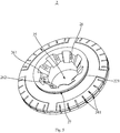
- the flame distributor 2 includes a top surface 22, a bottom surface 23, and an outer peripheral surface connecting the top surface 22 and the bottom surface 23.
- the first cavity 25 passing through the top surface 22 and the bottom surface 23 is defined in the middle of the flame distributor 2.
- the gas flaming cavity 21 is defined between the outer peripheral surface and the inner wall of the first cavity 25.
- the gas flaming cavity 21 has an open end downward.
- the second cavity 122 is defined in the middle of the second base 12, running through up and down.
- the gas mixing cavity 121 is spaced and arranged around the periphery of the second cavity 122.
- the gas mixing cavity 121 has an open end upward.
- the flame distributor 2 is engaged with the second base 12, so that the gas flaming cavity 21 and the gas mixing cavity 121 butts and communicates with each other.
- the first cavity 25 and the second cavity 122 are abutted, forming the through cavity 101.
- the top surface 22 of the flame distributor 2 is the horizontal plane where the highest point of the flame distributor 2 in the radial direction is arranged.
- the bottom surface 23 is the horizontal plane where the lowest point of the flame distributor 2 in the radical direction is arranged.
- the outer peripheral surface is configured to connect the top surface 22 and the bottom surface 23.
- the shape of the outer peripheral surface is not specifically limited herein, which can be designed according to practical requirements.
- the flame distributor 2 can be integrally formed or formed by splicing a plurality of parts.
- the flame distributor 2 is preferably integrally formed if its overall structure is relatively simple, thus simplifying its manufacturing and assembling processes so as to effectively reduce the production cost.
- the flame distributor 2 is preferably formed by splicing a plurality of parts, when some complicated structures need to be formed inside. As such, the manufacturing complexity of the flame distributor 2 can be reduced, and the cleaning inside the flame distributor 2 is convenient.
- a guiding surface 26 is arranged at the joint of the top surface 22 and the inner wall of the first cavity 25, and the guiding surface 26 tapers from top to bottom.
- the overspill can be guided, and quickly flow into the through cavity 101 via the flow guiding surface 26.
- a plurality of protrusions 261 are spaced and arranged on the guiding surface 26 along the circumferential direction, in which, a guiding groove 262 is defined between each adjacent two of the plurality of protrusions 261.
- the inner flame hole 211 is defined on the wall of the protrusions 261 contacting the guiding groove 262 and is communicated with the gas flaming cavity 21.
- the power of the burner 100 is more centralized and the heating is improved, by arranging a plurality of protrusions 261 on the flow guiding surface 26 and arranging an inner flame holes 211 on the wall of the protrusions 261 connecting the guiding groove 262 and is communicated with the gas flaming cavity 21.
- the arrangement of the inner flame holes 211 on the lateral wall of the protrusions 261 can resist wind and prevent the flame from extinguishing, compared to the arrangement that inner flame holes 211 is directly placed on the top surface 22 of the flame distributor 2. In the meanwhile, it can also be effectively prevented that overspill drips directly into the inner flame holes 211, enhancing the anti-blockage function.
- any protrusion 261 has a first side wall and a second side wall facing each other along the circumferential direction, and the inner flame holes 211 are all arranged on the first side wall.
- the inner flame holes 211 tends to have the same flame discharge direction circumferentially, forming a radial spiral structure, so that the flame is more uniform and centralized.
- the second wall can reflect on the flame sprayed from the inner flame holes 211, thereby further accumulating heat and improving thermal efficiency.
- the guiding groove 262 formed between two adjacent protrusions 261 can further guide the overspill which can flow into the through cavity 101 along the guiding groove 262.
- the inner flame holes 211 is arranged adjacent to the through cavity 101, external air can replenish into the inner flame holes 211 via the through cavity 101, and the gas combustion at the inner flame holes 211 is more complete, improving the combustion efficiency.
- an annular flame spreading groove 27 is defined at the joint of the top surface 22 and the outer peripheral surface.
- a plurality of middle flame holes 212 are defined on an inner wall along a circumferential direction of the flame spreading groove 27 and are communicated with the gas flaming cavity 21.
- the central flame holes 212 increase the heating area of the burner 100 effectively, so that the burner 100 can provide a uniform heating for cookware with a large bottom area.
- the flame ejected from the central flame holes 212 can be scattered along the flame spreading groove 27, making the flame uniform.
- an anti-block flange 221 is arranged extending outwards corresponding to flame outlets of the plurality of middle flame holes 212 on the top of the flame distributor 2, and the flame spreading groove 27 is arranged at an interval between the anti-block flange 221 and the flame outlets of the plurality of the middle flame holes 212.
- the shielding of the anti-block flange 221 may prevent the overspill from directly dripping into the flame spreading groove 27 and the central flame holes 212, by providing the anti-block flange 221, when overspill flows to the top of the flame distributor 2.
- the outer edge of the anti-block flange 221 is protruded from the outer edge of the flame outlet of the middle flame holes 212 to further ensure that overspill does not drip into the middle flame holes 212.
- the outer peripheral surface includes a first peripheral surface 24a, a second peripheral surface 24b and a third peripheral surface 24c.
- the first peripheral surface 24a is a surface extending downward from the top surface 22 and tapered from bottom to top;
- the second peripheral surface 24b is a surface extending upward from the bottom surface 23 and tapered from top to bottom;
- the third peripheral surface 24c is a column surface extending radially; an upper end of the third peripheral surface 24c is connected to the first peripheral surface 24a, and a lower end of the third peripheral surface 24c is connected to the second peripheral surface 24b.
- the flame distributor 2 appears like a flying object, which looks more beautiful and can provide an aesthetic sense visually.
- the overspill can slide down the tapered surface tapered and extended downward, when dripping onto the first peripheral surface 24a of the flame distributor 2, that is, the first peripheral surface 24a plays a certain role in guiding the spill.
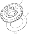
- the flame distributor 2 may be integrally formed or separately arranged.
- the flame distributor 2 includes an outer flame distributor 2a and an inner flame distributor 2b.
- the outer flame distributor 2a and the inner flame distributor 2b are both disk-shaped, the outer flame distributor 2a is engaged on the top of the inner flame distributor 2b, and a gas flaming cavity 21 is defined between the outer flame distributor 2a and the inner flame distributor 2b.
- the top surface 22 is defined on the top of the outer flame distributor 2a
- the first peripheral surface 24a and the third peripheral surface 24c are both arranged on the outer flame distributor 2a.
- a part of the second peripheral surface 24b is arranged on the outer flame distributor 2a, the other thereof is arranged on the inner flame distributor 2b.
- the bottom surface 23 is arranged on the bottom of the inner flame distributor 2b.
- the complete flame distributor 2 is assembled by splicing the outer flame distributor 2a and the inner flame distributor 2b, so that the overall manufacturing complexity of the flame distributor 2 has been reduced, and the assembling has been simplified.
- splicing members can be arranged regarding the flame distributor 2, which should be included in the scope of the present application.
- a plurality of outer flame holes 213 are spaced and arranged at the inner wall of the gas flaming cavity 21 corresponding to the third circumferential surface 24c at a circumferential direction.
- a plurality of flame stabilizing grooves 241 are arranged along the third circumferential surface 24c and are communicated with the outer flame holes 213.
- the heating radius of the burner 100 is further increased by providing the outer flame holes 213.
- the flame distributor 2 can provide a three-ring flame heating system by the matching of the three, so that more heating combination is available for the user to chose.
- the contact area between the flame and the burner 100 increase, by providing the flame stabilizing groove 241, thereby stabilizing the flame ejected from the outer flame holes 213 and avoiding the flame lift-off.
- the first circumferential surface 24a is inclined between the central flame holes 212 and the outer flame holes 213, the first circumferential surface 24a can also play a certain role in spreading the flame. The ignited gas at the central flame holes 212 will quickly spread to the outer flame holes 213 along the first circumferential surface 24a, further improving the combustion rate.
- At least one flame stabilizing portion is provided in the flame stabilizing groove 241 forming a "T" shape, in order to increase the stabilization effect.
- the flame stabilizing groove 241 includes at least one flame holding part arranged in the flame stabilizing groove 241 forming a "T" shape, that is, the flame holding part includes at least two elongated strip grooves to form a "T" shape structure.
- the flame stabilizing groove 241 effectively increases the contact area between the flame and the burner 100, further improving the stabilizing effect of the flame distributor 2.
- Specific structures of the flame stabilizing groove 241 includes a "T" shape, an inverted “T” shape, a “cross” shape, an “earth” shape, etc., as long as the two strip grooves cross one another to form a flame stabilizing part with a "T” shape.
- the T-shaped structure referred to herein does not limit the two grooves to intersect vertically, for example, when the two grooves crossing with a certain angle, should also fall within the protection scope of the present application.
- the flame stabilizing groove 241 arranged in a cross shape can further increase the contact area between the flame and the burner 100 and further improve the flame stabilizing effect of the flame distributor 2.
- the flame stabilizing groove 241 includes a first strip groove extending along the circumferential direction of the third circumferential surface 24c, and a second strip groove extending along the vertical direction.
- the first strip groove intersects with the second strip groove to form a cross structure, and the second strip groove is divided into an upper strip groove and a lower strip groove by the first strip groove.
- the first strip groove is respectively communicated with the upper strip groove and the lower strip groove, to spread the flame.
- the shape of the upper strip groove and the lower strip groove may help the stabilization of the flame.
- a plurality of first strip grooves are communicated with each other to form a circumferential annular groove
- the second strip grooves are communicated with each other in an "up-down" direction, that is, the upper strip groove and the lower strip groove are communicated with each other.
- flame can be exceedingly spread at the first strip groove in the up-down direction and the left-right direction.
- the second strip groove is communicated up and down, so that the potential overspill can flow from top to bottom along the second strip groove, preventing blockage regarding the flame stabilizing groove 241 and the outer flame holes 213.
- the gas combustion is exceedingly complete, and the gas combustion efficiency is thus effectively improved.
- the embodiment of the present application further provides a burner nozzle base 1a, which includes a base, on which two or more gas channels are arranged.
- the two or more gas channels are extended along different radial directions of the base; a first end 11a of the two or more gas channels are configured to connect an air inflow pipe; a second end 12a of the two or more of gas channels are configured to mount a nozzle and to eject gas to different burner ejectors 1.
- the burner nozzle base 1a is connected to the ejector 1 and the air inflow pipe.
- the gas enters the nozzle base 1a from the gas inflow pipe, followed by being ejected to the ejector 1 through the nozzle (not shown in the figure) of the nozzle base 1a.
- the gas enters into the flame distributor 2 before being ignited and combusted near the flame hole. Because of the two gas channels' arrangement on one base, and their connection to the corresponding number of ejectors 1, a new centralized gas supply has been proposed, and centralized gas supply to a plurality of ejectors 1 has been fulfilled.
- the gas inflow pipe can introduce the gas into the shell bracket from the lateral side or the bottom of the burner, so that the space of the shell bracket can be fully and reasonably utilized, and the structure is compact and the space efficiency is high.
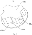
- the base in order to facilitate the connection between the burner nozzle base 1a and the ejector 1, the base includes a mounting plate 100a shown in Fig. 11 and a protruded block 101 thereon.
- the mounting plate 100a is configured to fix the nozzle base 1a of the burner onto the ejector 1, and a gas channel is arranged on the protruded block 101a.
- assembling hole 20 is arranged on the ejector 1 correspondingly.
- the shape of assembling hole 20 is matched with that of the protruded block 101a.
- the mounting plate 100a is provided with a plurality of assembling holes 10a to connect with the ejector 1.
- the ejector 1 is provided with assembling holes 10a, and the nozzle base 1a and the ejector 1 can be fixed by the screws extending into the assembling holes 10a.
- the number of assembling holes 10a is two, although other numbers can also be possible. It should be noted that the connection between the burner nozzle base 1a and the ejector 1 is not limited to screws, as long as the technical effect of the present application can be fulfilled.
- the first end 11a of the gas channel is arranged on the bottom surface of the mounting plate 100a, and the second end 12a of the gas channel is arranged on the lateral surface of the protruded block 101a.
- the first end 11a of the gas channel is arranged on the bottom surface of the mounting plate 100a, facilitating the connection with the air inflow pipe, the overall layout of the air inflow pipe as well as space efficiency.
- the second end 12a of the gas channel is opened on the lateral side of the protruded block 101a, keeping itself horizontally arranged. In the present embodiment, it is also arranged such that the second end 12a is coaxial with the ejector 1, thereby the ejector 1 may eject the flame horizontally, which may improve the ejecting capability of the burner.
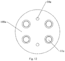
- the bottom surface of the mounting plate 100a is provided with four connecting holes, i.e., the second ends 12a of the four gas channels are spaced apart from each other, and are all configured to connect different gas inflow pipes.
- four intake pipes are connected in total, each of which can be independently controlled on and off.
- the first end 11a of each gas channel converges and connects the same gas inflow pipe, i.e. one gas inflow pipe corresponds to a plurality of nozzle bases, which should be also included in the technical solution of the present application.
- the first end 11a of each gas channel is the same, while the second ends 12a of each gas channel are arranged with space intervals from each other.
- the embodiment can greatly reduce the number of air inflow pipes and valves, which is convenient for assembling and processing, and improves production and assembling efficiency and reduces cost.
- gas channels are arranged, which are respectively the first channel, the second channel, the third channel and the fourth channel in sequence.
- the second end 12a of the first channel and the second end 12a of the third channel connect and form a first connection line
- the second end 12a of the second channel and that of the fourth channel connect and form a second connection line.
- the first connection line and the second connection line form an X-shaped structure.
- the nozzle base 1a of the burner and the ejector 1 forms the X-shaped structure, so that the entire burner appears like an unmanned aerial vehicle, which is beautiful and senses technological.
- the number of gas channels may be other, such as three or five, which is not limited in the present application.
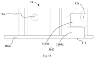
- the gas channel 3103 includes a connecting portion 3103a and an accelerating portion 3103b shown in Fig. 13 .
- the connecting portion 3103a communicates with the first end 11a of the gas channel.
- One end of the accelerating portion 3103b communicates with the first end 11a of the gas channel, while the other end communicates with the second end 12a of the gas channel.
- the aperture of the accelerating portion 3103b is smaller than that of the connecting portion 3103a.
- the flow rate of the gas is increased in the accelerating portion 3103b, when the gas flows in the gas channel 3103, because of the relatively smaller aperture regarding the accelerating portion 3103b.
- the gas flow rate increases through the second end 12a of the gas channel, further improving the ejection of the gas at the second end 12a of the gas channel.
- the flowing direction will inevitably change of the gas in the gas channel 3103.
- the joint is smoothly transited between the second end 12a of the gas channel and the accelerating portion 3103b, so that the gas in the accelerating portion 3103b can easily flow to the second end 12a of the gas channel along the transited curved surface, thereby reducing the flow resistance of the gas in the nozzle base 1a.
- the aperture of the second end 12a of the gas channel may be set smaller than that of the accelerating portion 3103b.
- the flow rate of the gas is increased in the accelerating portion 3103b, thereby increasing the flow rate of the gas at the second end 12a of the gas channel and improving the ejection of the gas at the second end 12a of the gas channel.
- the axis of the first end 11a of the gas channel extends vertically. And a plurality of intake pipes are arranged vertically, thereby facilitating the layout and installation of the intake pipes of the burner 100.
- the first end 11a of the gas channel, the connecting portion 3103a and the accelerating portion 3103b are preferably arranged concentrically, thereby reducing the flow resistance of the gas channel 3103 to the gas.
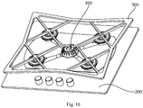
- the present application also provides a gas stove, as shown in Fig. 10 , which includes a panel 200, a pan support 300 and a burner 100, in which, the pan support 300 is configured to support the pan above the panel 200.
- the burner 100 is arranged below the pan support 300.
- the specific structure of the burner 100 can be referred to aforementioned embodiments. Since the gas stove adopts all the technical solutions of the aforementioned embodiments, it also has all the beneficial effects brought by the technical solutions of the aforementioned embodiments, and will not be repeated herein.
- the burner 100 can be installed in various ways. For example, the burner 100 can be installed on the panel 200 and arranged above the panel 200; or the gas stove further includes a bottom casing (not shown) arranged below the panel 200, and the burner 100 is arranged below the panel 200 and installed on the bottom casing.
- the bottom of the pan support 300 is provided with an column extending downward into the through cavity 101 at a position corresponding to the through cavity 101 of the burner 100, so that the pan support 300 can be placed more stably.
- the pan support 300 includes a first end for supporting the pot body and a second end opposite to the first end, in which the second end is extended towards the flame distributor 2 and provided with a vertical stand 51 which providing an inner cavity.
- the vertical stand 51 is vertically arranged in the through cavity 101 in which a temperature sensor is accommodated.
- the gas When in use, the gas enters the nozzle base from the gas inflow pipe, followed by being ejected to the ejector 1 through the nozzle (not shown in the figure) of the nozzle base. Guided by the ejector 1, the gas enters into the flame distributor 2 before being ignited and combusted at the flame hole.
- the pan support 300 can support the pot body, and the pan support 300 can be taken out from the flame distributor 2.
- the stand 51 of the pan support 300 is placed on the through cavity 101 of the flame distributor 2 as the leg of the pan support 300.
- the through cavity 101 of the flame distributor 2 aims to replenish air and also to remove impurities such as soup and water. Further, the through cavity 101 also serves as an assembling channel for the temperature sensor.
- Real-time temperature detection is carried out by a temperature sensor so as to cease the flame in case that the temperature is exceedingly high, preventing burn-out.
- the temperature sensing in the prior art is usually interfered by flame generated during the gas combustion, resulting in detection error of the temperature sensing.
- an inner cavity is skillfully arranged on the vertical stand 51 of the pan support 300, in which the temperature sensor is accommodated in the inner cavity.
- the flame interference produced during gas combustion has been overcome during the temperature detection.
- the detection by the temperature sensor is thus more accurate. Further, the flame can be stopped timely when burn-out is detected.
- the present embodiment can also improve the service life of the temperature sensor.
- the pan support 300 correspondingly has different shapes. As long as the temperature sensor is accommodated in the pan support 300 to avoid flame interference, the technical effect of the present application can be fulfilled.
- the gas stove includes a plurality of flame distributors 2, and the pan support 300 includes a plurality of vertical stands 51 which one-to-one corresponds to the through cavities 101 of the flame distributors 2. In the embodiment shown in Fig. 10 , four flame distributors 2 are arranged. Accordingly, the pan support 300 includes four vertical stands 51 to form a four-corner support. It should be clear that when other numbers of flame distributors 2 and vertical stands 51 are arranged, for example, three or five, it should be also included in the technical solution of the present application.
- temperature sensors can be respectively arranged in a plurality of vertical stands 51, and each temperature sensor corresponds to one flame distributor 2, so that the burn-out of each flame distributor 2 can be fed back more quickly.
- a part of the vertical stand 51 is provided with a temperature sensor. Since the pan support 300 itself has good thermal conductivity, when having a plurality of holders, only one or two of the vertical holders 51 are provided with temperature sensors, which can also feed back the burn-out emergency by thermal conductivity with a low cost.
- the pan support 300 may have various possible structures.
- the pan support 300 is a frame structure, which is convenient to support and place the bottom of the pot and can ensure the flame to fully contacts with the bottom of the pot.
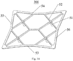
- the pan support 300 includes an X-shape beam 52, and the vertical stand 51 is perpendicular to the plane of the X-shape beam 52 and is arranged at the intersection of the X-shape beam 52.
- four X-shape beams 52 are arranged, which can be connected and integrated into an entire structure.
- the pan support 300 further includes a front frame 53 and a rear frame 54 which are oppositely arranged, as well as a left frame 55 and a right frame 56 which are oppositely arranged.
- the front frame 53, the left frame 55, the rear frame 54 and the right frame 56 are connected in sequence, and the definition of each frame positioned is based on that shown in Fig. 14 .
- the above structure is stable and reliable, especially for frying pans.
Landscapes
- Engineering & Computer Science (AREA)
- Chemical & Material Sciences (AREA)
- Combustion & Propulsion (AREA)
- Mechanical Engineering (AREA)
- General Engineering & Computer Science (AREA)
- Gas Burners (AREA)
Applications Claiming Priority (7)
| Application Number | Priority Date | Filing Date | Title |
|---|---|---|---|
| CN201810305119.8A CN108458340B (zh) | 2018-04-04 | 2018-04-04 | 燃气灶 |
| CN201810305829.0A CN108458341B (zh) | 2018-04-04 | 2018-04-04 | 燃烧器喷嘴座及燃气灶 |
| CN201810305826.7A CN108413397B (zh) | 2018-04-04 | 2018-04-04 | 燃烧器和燃烧厨具 |
| CN201820485018.9U CN208058842U (zh) | 2018-04-04 | 2018-04-04 | 燃烧器引射管及燃气灶 |
| CN201820484800.9U CN208108098U (zh) | 2018-04-04 | 2018-04-04 | 喷嘴座、燃烧器及燃烧厨具 |
| CN201820484982.XU CN208058837U (zh) | 2018-04-04 | 2018-04-04 | 燃烧器引射管及燃气灶 |
| PCT/CN2018/116394 WO2019192185A1 (zh) | 2018-04-04 | 2018-11-20 | 燃烧器引射管、燃烧器及燃烧厨具 |
Publications (2)
| Publication Number | Publication Date |
|---|---|
| EP3604918A1 true EP3604918A1 (de) | 2020-02-05 |
| EP3604918A4 EP3604918A4 (de) | 2020-09-16 |
Family
ID=68099837
Family Applications (1)
| Application Number | Title | Priority Date | Filing Date |
|---|---|---|---|
| EP18913472.9A Pending EP3604918A4 (de) | 2018-04-04 | 2018-11-20 | Ausstossrohr eines brenners, brenner und brennerkocher |
Country Status (2)
| Country | Link |
|---|---|
| EP (1) | EP3604918A4 (de) |
| WO (1) | WO2019192185A1 (de) |
Cited By (1)
| Publication number | Priority date | Publication date | Assignee | Title |
|---|---|---|---|---|
| US11808448B2 (en) | 2020-11-24 | 2023-11-07 | Whirlpool Corporation | Burner assemblies for a cooktop |
Families Citing this family (4)
| Publication number | Priority date | Publication date | Assignee | Title |
|---|---|---|---|---|
| CN212029619U (zh) * | 2019-11-13 | 2020-11-27 | 博西华电器(江苏)有限公司 | 燃烧器火盖及燃气灶 |
| CN113757662B (zh) * | 2020-06-04 | 2025-02-07 | 宁波方太厨具有限公司 | 一种上进风燃烧器以及应用有该上进风燃烧器的灶具 |
| CN115143462B (zh) * | 2021-03-29 | 2025-06-20 | 佛山市顺德区美的洗涤电器制造有限公司 | 燃烧器和燃气灶 |
| CN115949940A (zh) * | 2021-10-09 | 2023-04-11 | 佛山市顺德区美的洗涤电器制造有限公司 | 火盖和具有其的炉头、燃烧器 |
Family Cites Families (20)
| Publication number | Priority date | Publication date | Assignee | Title |
|---|---|---|---|---|
| US3219098A (en) * | 1963-02-28 | 1965-11-23 | Roper Corp Geo D | Burner for gas range |
| DE3123751C3 (de) * | 1981-06-15 | 1998-01-29 | Sabaf Spa | Gasbrenner für eine Kochplatte |
| DE19637666A1 (de) * | 1996-09-16 | 1998-03-26 | Schott Glaswerke | Druckregeleinrichtung für die Gaszufuhr zu einer Gaskocheinrichtung mit unter einer durchgehenden Kochfläche angeordneten Gasstrahlungsbrennern |
| JP3691448B2 (ja) * | 2002-03-22 | 2005-09-07 | リンナイ株式会社 | バーナ |
| CN102901098B (zh) * | 2012-10-23 | 2015-10-07 | 江苏中圣高科技产业有限公司 | 地面火炬多头高效预混型燃烧系统 |
| CN203349271U (zh) * | 2012-12-24 | 2013-12-18 | 中山古奇诺智能厨房有限公司 | 微分动力燃气灶具燃烧器 |
| CN203757712U (zh) * | 2014-01-09 | 2014-08-06 | 周崇高 | 高效聚能燃烧器 |
| CN104896476B (zh) * | 2015-05-25 | 2017-10-10 | 况军 | 一种高效节能环保式燃烧器 |
| CN205227321U (zh) * | 2015-11-20 | 2016-05-11 | 中山百得厨卫有限公司 | 一种新型上进风燃烧器 |
| CN206018622U (zh) * | 2016-08-31 | 2017-03-15 | 蒋志海 | 一种上进风直喷多头红外线燃烧器 |
| CN206514296U (zh) * | 2016-12-01 | 2017-09-22 | 中山金木楠智能家居有限公司 | 一种全上进风式灶具燃烧器及灶具 |
| CN208058832U (zh) * | 2018-04-04 | 2018-11-06 | 广东美的厨房电器制造有限公司 | 燃烧器喷嘴座及燃气灶 |
| CN108458340B (zh) * | 2018-04-04 | 2019-06-28 | 广东美的厨房电器制造有限公司 | 燃气灶 |
| CN108458341B (zh) * | 2018-04-04 | 2019-06-28 | 广东美的厨房电器制造有限公司 | 燃烧器喷嘴座及燃气灶 |
| CN108413397B (zh) * | 2018-04-04 | 2019-06-28 | 佛山市顺德区美的洗涤电器制造有限公司 | 燃烧器和燃烧厨具 |
| CN208108098U (zh) * | 2018-04-04 | 2018-11-16 | 广东美的厨房电器制造有限公司 | 喷嘴座、燃烧器及燃烧厨具 |
| CN208058836U (zh) * | 2018-04-04 | 2018-11-06 | 广东美的厨房电器制造有限公司 | 燃烧器和燃烧厨具 |
| CN208058831U (zh) * | 2018-04-04 | 2018-11-06 | 广东美的厨房电器制造有限公司 | 燃气灶 |
| CN208058837U (zh) * | 2018-04-04 | 2018-11-06 | 广东美的厨房电器制造有限公司 | 燃烧器引射管及燃气灶 |
| CN208058842U (zh) * | 2018-04-04 | 2018-11-06 | 广东美的厨房电器制造有限公司 | 燃烧器引射管及燃气灶 |
-
2018
- 2018-11-20 EP EP18913472.9A patent/EP3604918A4/de active Pending
- 2018-11-20 WO PCT/CN2018/116394 patent/WO2019192185A1/zh not_active Ceased
Cited By (1)
| Publication number | Priority date | Publication date | Assignee | Title |
|---|---|---|---|---|
| US11808448B2 (en) | 2020-11-24 | 2023-11-07 | Whirlpool Corporation | Burner assemblies for a cooktop |
Also Published As
| Publication number | Publication date |
|---|---|
| WO2019192185A1 (zh) | 2019-10-10 |
| EP3604918A4 (de) | 2020-09-16 |
Similar Documents
| Publication | Publication Date | Title |
|---|---|---|
| EP3604918A1 (de) | Ausstossrohr eines brenners, brenner und brennerkocher | |
| CN104713087B (zh) | 底杯盖及燃烧器及燃气用具 | |
| CN110410784A (zh) | 炉头、燃烧器和燃气灶 | |
| CN111853789B (zh) | 一种平板式燃烧器及平板式燃气灶 | |
| CN210951313U (zh) | 燃烧器和燃气灶 | |
| CN205279087U (zh) | 上进风式多燃气通道灶具燃烧器 | |
| CN110617474A (zh) | 燃烧器的火盖、燃烧器和燃气灶具 | |
| CN208058847U (zh) | 火盖、燃烧器和燃气灶具 | |
| CN108413397B (zh) | 燃烧器和燃烧厨具 | |
| CN108458340B (zh) | 燃气灶 | |
| CN213713147U (zh) | 一种红外燃烧器 | |
| CN208058831U (zh) | 燃气灶 | |
| CN110617475B (zh) | 火盖、燃烧器和家用燃气装置 | |
| CN111121027B (zh) | 一种上进风燃烧器以及应用有该上进风燃烧器的灶具 | |
| JP2013124851A (ja) | ガスコンロ | |
| CN208058832U (zh) | 燃烧器喷嘴座及燃气灶 | |
| CN108458341B (zh) | 燃烧器喷嘴座及燃气灶 | |
| CN208058837U (zh) | 燃烧器引射管及燃气灶 | |
| CN111964128B (zh) | 一种灶用隔热罩以及应用有该隔热罩的燃气灶 | |
| CN208058842U (zh) | 燃烧器引射管及燃气灶 | |
| CN209944322U (zh) | 一种上进风燃烧器以及应用有该上进风燃烧器的灶具 | |
| CN110848689B (zh) | 一种上进风燃烧器 | |
| CN208058846U (zh) | 火盖、燃烧器和燃烧厨具 | |
| CN111121028B (zh) | 一种上进风燃烧器以及应用有该上进风燃烧器的灶具 | |
| CN219140849U (zh) | 聚能锅架及具有其的燃气灶具 |
Legal Events
| Date | Code | Title | Description |
|---|---|---|---|
| STAA | Information on the status of an ep patent application or granted ep patent |
Free format text: STATUS: THE INTERNATIONAL PUBLICATION HAS BEEN MADE |
|
| PUAI | Public reference made under article 153(3) epc to a published international application that has entered the european phase |
Free format text: ORIGINAL CODE: 0009012 |
|
| STAA | Information on the status of an ep patent application or granted ep patent |
Free format text: STATUS: REQUEST FOR EXAMINATION WAS MADE |
|
| 17P | Request for examination filed |
Effective date: 20191023 |
|
| AK | Designated contracting states |
Kind code of ref document: A1 Designated state(s): AL AT BE BG CH CY CZ DE DK EE ES FI FR GB GR HR HU IE IS IT LI LT LU LV MC MK MT NL NO PL PT RO RS SE SI SK SM TR |
|
| AX | Request for extension of the european patent |
Extension state: BA ME |
|
| RIC1 | Information provided on ipc code assigned before grant |
Ipc: F23D 14/06 20060101ALI20200507BHEP Ipc: F23D 23/00 20060101ALI20200507BHEP Ipc: F23D 14/08 20060101ALI20200507BHEP Ipc: F24C 3/08 20060101ALI20200507BHEP Ipc: F23D 14/64 20060101ALI20200507BHEP Ipc: F23D 14/26 20060101AFI20200507BHEP |
|
| REG | Reference to a national code |
Ref country code: DE Ref legal event code: R079 Free format text: PREVIOUS MAIN CLASS: F23D0014020000 Ipc: F23D0014260000 |
|
| A4 | Supplementary search report drawn up and despatched |
Effective date: 20200813 |
|
| RIC1 | Information provided on ipc code assigned before grant |
Ipc: F23D 14/26 20060101AFI20200807BHEP Ipc: F23D 14/64 20060101ALI20200807BHEP Ipc: F23D 23/00 20060101ALI20200807BHEP Ipc: F23D 14/08 20060101ALI20200807BHEP Ipc: F24C 3/08 20060101ALI20200807BHEP Ipc: F23D 14/06 20060101ALI20200807BHEP |
|
| DAV | Request for validation of the european patent (deleted) | ||
| DAX | Request for extension of the european patent (deleted) | ||
| STAA | Information on the status of an ep patent application or granted ep patent |
Free format text: STATUS: EXAMINATION IS IN PROGRESS |
|
| 17Q | First examination report despatched |
Effective date: 20230213 |