EP3604084A1 - Fahrgestell zum tragen von automobilkarosserien und verschiedene spezifisch ausgestattete vorrichtungen als lasten - Google Patents
Fahrgestell zum tragen von automobilkarosserien und verschiedene spezifisch ausgestattete vorrichtungen als lasten Download PDFInfo
- Publication number
- EP3604084A1 EP3604084A1 EP18770709.6A EP18770709A EP3604084A1 EP 3604084 A1 EP3604084 A1 EP 3604084A1 EP 18770709 A EP18770709 A EP 18770709A EP 3604084 A1 EP3604084 A1 EP 3604084A1
- Authority
- EP
- European Patent Office
- Prior art keywords
- chassis
- supporting means
- cargo box
- automobile
- coupling
- Prior art date
- Legal status (The legal status is an assumption and is not a legal conclusion. Google has not performed a legal analysis and makes no representation as to the accuracy of the status listed.)
- Granted
Links
Images




Classifications
-
- B—PERFORMING OPERATIONS; TRANSPORTING
- B60—VEHICLES IN GENERAL
- B60P—VEHICLES ADAPTED FOR LOAD TRANSPORTATION OR TO TRANSPORT, TO CARRY, OR TO COMPRISE SPECIAL LOADS OR OBJECTS
- B60P1/00—Vehicles predominantly for transporting loads and modified to facilitate loading, consolidating the load, or unloading
- B60P1/64—Vehicles predominantly for transporting loads and modified to facilitate loading, consolidating the load, or unloading the load supporting or containing element being readily removable
- B60P1/6418—Vehicles predominantly for transporting loads and modified to facilitate loading, consolidating the load, or unloading the load supporting or containing element being readily removable the load-transporting element being a container or similar
- B60P1/6445—Vehicles predominantly for transporting loads and modified to facilitate loading, consolidating the load, or unloading the load supporting or containing element being readily removable the load-transporting element being a container or similar the load-transporting element being shifted only vertically
-
- B—PERFORMING OPERATIONS; TRANSPORTING
- B60—VEHICLES IN GENERAL
- B60P—VEHICLES ADAPTED FOR LOAD TRANSPORTATION OR TO TRANSPORT, TO CARRY, OR TO COMPRISE SPECIAL LOADS OR OBJECTS
- B60P3/00—Vehicles adapted to transport, to carry or to comprise special loads or objects
-
- B—PERFORMING OPERATIONS; TRANSPORTING
- B60—VEHICLES IN GENERAL
- B60P—VEHICLES ADAPTED FOR LOAD TRANSPORTATION OR TO TRANSPORT, TO CARRY, OR TO COMPRISE SPECIAL LOADS OR OBJECTS
- B60P7/00—Securing or covering of load on vehicles
- B60P7/06—Securing of load
- B60P7/13—Securing freight containers or forwarding containers on vehicles
-
- B—PERFORMING OPERATIONS; TRANSPORTING
- B62—LAND VEHICLES FOR TRAVELLING OTHERWISE THAN ON RAILS
- B62D—MOTOR VEHICLES; TRAILERS
- B62D21/00—Understructures, i.e. chassis frame on which a vehicle body may be mounted
- B62D21/09—Means for mounting load bearing surfaces
-
- B—PERFORMING OPERATIONS; TRANSPORTING
- B62—LAND VEHICLES FOR TRAVELLING OTHERWISE THAN ON RAILS
- B62D—MOTOR VEHICLES; TRAILERS
- B62D24/00—Connections between vehicle body and vehicle frame
-
- B—PERFORMING OPERATIONS; TRANSPORTING
- B62—LAND VEHICLES FOR TRAVELLING OTHERWISE THAN ON RAILS
- B62D—MOTOR VEHICLES; TRAILERS
- B62D33/00—Superstructures for load-carrying vehicles
- B62D33/077—Superstructures for load-carrying vehicles characterised by the connection of the superstructure to the vehicle frame
-
- B—PERFORMING OPERATIONS; TRANSPORTING
- B62—LAND VEHICLES FOR TRAVELLING OTHERWISE THAN ON RAILS
- B62D—MOTOR VEHICLES; TRAILERS
- B62D63/00—Motor vehicles or trailers not otherwise provided for
- B62D63/02—Motor vehicles
- B62D63/025—Modular vehicles
-
- B—PERFORMING OPERATIONS; TRANSPORTING
- B66—HOISTING; LIFTING; HAULING
- B66C—CRANES; LOAD-ENGAGING ELEMENTS OR DEVICES FOR CRANES, CAPSTANS, WINCHES, OR TACKLES
- B66C23/00—Cranes comprising essentially a beam, boom, or triangular structure acting as a cantilever and mounted for translatory of swinging movements in vertical or horizontal planes or a combination of such movements, e.g. jib-cranes, derricks, tower cranes
- B66C23/18—Cranes comprising essentially a beam, boom, or triangular structure acting as a cantilever and mounted for translatory of swinging movements in vertical or horizontal planes or a combination of such movements, e.g. jib-cranes, derricks, tower cranes specially adapted for use in particular purposes
- B66C23/36—Cranes comprising essentially a beam, boom, or triangular structure acting as a cantilever and mounted for translatory of swinging movements in vertical or horizontal planes or a combination of such movements, e.g. jib-cranes, derricks, tower cranes specially adapted for use in particular purposes mounted on road or rail vehicles; Manually-movable jib-cranes for use in workshops; Floating cranes
- B66C23/44—Jib-cranes adapted for attachment to standard vehicles, e.g. agricultural tractors
-
- B—PERFORMING OPERATIONS; TRANSPORTING
- B60—VEHICLES IN GENERAL
- B60Y—INDEXING SCHEME RELATING TO ASPECTS CROSS-CUTTING VEHICLE TECHNOLOGY
- B60Y2200/00—Type of vehicle
- B60Y2200/10—Road Vehicles
- B60Y2200/14—Trucks; Load vehicles, Busses
- B60Y2200/145—Haulage vehicles, trailing trucks
Definitions
- the present invention relates to an automobile chassis for carrying an automobile body and various specially-equipped devices as loads, and more specifically to an automobile chassis for carrying an automobile body and various specially-equipped devices as loads, which is configured to enable various types of cargo boxes (load sides) intended to carry cargos or people and various types of special equipment designed to be suitable for the transportation of a special cargo or a special purpose to be conveniently and replaceably loaded, and thus enables a single chassis to be used for various purposes, thereby improving cost reduction, convenience functionality, and maintenance, and which, in particular, provides excellent coupling force and also allows a coupling location to be varied according to the type or center of gravity of a load, thereby enabling stable loading.
- cargo boxes load sides
- special equipment designed to be suitable for the transportation of a special cargo or a special purpose
- an automobile chassis is equipped with rolling wheels on the bottom thereof, is connected to a towing vehicle which is a device for generating power, and is loaded with a cargo box on the top thereof and used to carry various types of cargos.
- Such an automobile chassis generally includes a C- or H-type chassis body and a cross-member which connects the chassis body in lateral directions.
- a chassis in which coupling devices are provided at the respective corners of the top of the chassis and a container box can be selectively mounted on and demounted from the chassis.
- a trailer chassis for loading a container which disclosed in Korean Utility Model Registration Application Publication No. 20-1998-0025022 (published on July 25, 1998 ), has been proposed. Referring to this publication, it is proposed to form a through hole for inserting a double cone when loading a container on the trailer chassis, and thus the corner portions of the chassis can be easily identified even at a long distance, thereby facilitating the loading.
- the chassis has been proposed to load only a standardized container as a container-dedicated chassis, and the use thereof has been limited. Furthermore, the chassis has problems in that a clearance is generated due to a load or no-load action and coupling strength is weak.
- various types of vehicles such as passenger vans and cars for transporting people, various types of trucks for transporting cargoes, and various types of specially-equipped cars equipped with special equipment, such as cargo cars, truck mixers, cranes, and tank trucks.
- pieces of newly developed equipment which are difficult to classify are becoming widespread.
- the present invention has been conceived to overcome the above-described problems, and an object of the present invention is to provide an automobile chassis for (or capable of) carrying an automobile body and various specially-equipped devices as loads, which is configured to enable various types of cargo boxes intended to carry cargos or people and various types of special equipment designed to be suitable for the transportation of a special cargo or a special purpose to be conveniently and replaceably loaded, and thus enables a single chassis to be used for various purposes, thereby improving cost reduction, convenience functionality, and maintenance, and which, in particular, provides excellent coupling force and also allows a coupling location to be varied according to the type or center of gravity of a load, thereby enabling stable loading.
- the present invention provides an automobile chassis for carrying an automobile body and various specially-equipped devices as loads, the automobile chassis including: a chassis body which is provided with wheels on the bottom thereof; and mounting devices which are symmetrically disposed on both sides of the chassis body, wherein the mounting devices replaceably mount one of various types of cargo boxes or various special equipment which is seated on the top surface of the chassis body; wherein each of the mounting devices includes: a supporting means which is coupled to the chassis body and supports the cargo box; and a coupling means which fastens the cargo box and the supporting means in order to prevent the occurrence of a clearance by firmly coupling them.
- the supporting means includes: a fastening jig which is fastened to the chassis body; a vertically movable member which includes a body configured to be disposed on one side surface of the fastening jig, a vertically movable element configured to be vertically movably provided on the body, and a knob configured to restrain the movement of the vertically movable element; a support member which includes a housing configured to be forwardly and rearwardly rotatably mounted on the vertically movable element via a hinge and a support lever configured to be provided to be selectively pulled out of and retracted into the housing in lateral directions and configured such that a vertical through hole is formed at an end thereof; and a guide member which includes a guide configured to be provided above the through hole of the support lever, to have a hollow inside, and to have a conical shape an outer diameter of which decreases upward, and a guide cap configured to be attached to a side surface of the cargo box and to have an inner diameter which is the same shape as the
- the automobile chassis further includes: auxiliary supporting means which are mounted on the chassis body so that they are located on the front and rear sides of the supporting means and supports an end of the support member.
- the coupling means includes: a bolt rod which passes through the supporting means downward in order to couple the cargo box and the supporting means and through one side surface of which is formed an insertion hole passing through the side surface in lateral directions; a nut member which is tightened onto the bolt rod passing through the bottom of the main supporting means downward, on a side surface of which is formed a coupling hole passing through the side surface in lateral directions, on the upper outer circumference of which is formed a large nut portion, and on the lower outer circumference of which is formed a small nut portion; and a fastening pin which prevents the bolt rod from being freely separated by sequentially passing through the coupling hole and the insertion hole of the bolt rod from a side surface of the nut member, thereby performing fastening.
- the automobile chassis is configured to enable various types of cargo boxes intended to carry cargos or people and various types of special equipment designed to be suitable for the transportation of a special cargo or a special purpose to be conveniently and replaceably loaded, and thus enables a single chassis to be used for various purposes, thereby improving cost reduction, convenience functionality, and maintenance.
- excellent coupling force is provided via the coupling means and also a coupling location may be varied according to the type or center of gravity of a load by the variation operation of the main supporting means and the auxiliary supporting means, thereby enabling any type of cargo box to be stably loaded.
- the present invention is an invention which relates to a chassis for carrying an automobile body and special equipment or devices having various types of functions as simple loads.
- the components of an automobile are basically divided into: a chassis into which a frame configured to form a skeleton, a power generation device, a traveling and steering device, various types of auxiliary devices, etc. are combined; and a body which includes a loading part including a passenger part, a cargo box, and special equipment having various types of functions.
- An object of the present invention is to propose a chassis having a functional structure which may be applied to all frame chassis structure vehicles except for a monocoque body-type vehicle, thereby realizing convenience and economical maximization by using a body as a simple load.
- classification may be ambiguous in terms of specially-equipped vehicles. It is also true that there is confusion in the legislation and regulation of laws.
- a body or special items or pieces of special equipment having various functions which act as a body are merely loads in terms of a loading aspect of loading or mounting on a vehicle, a driving function, and driving safety.
- the present invention is characterized in that such a loading box and such a loading part are carried as loads, and thus almost all loading parts and special items having various functions may be carried by a commercial vehicle as loads due to the convenience of attachment and detachment functions.
- the prevent invention is intended to construct a single chassis vehicle as a vehicle capable of loading or replaceably loading multiple and multifunctional loads, thereby improving maintenance, cost reduction, convenience functions, etc. Accordingly, when the present invention is practiced, it is obvious that the above-described classification of vehicles according to their use may become meaningless.
- a twist lock device which may be considered to have similarity with the present invention and is applied to a method of attaching to and detaching from a container chassis, may be considered, but its functions and characteristics are completely different.
- the U or I bolt pin fastening method is difficult to allow a target to be a load due to the use of a large and heavy tool in installation and detachment, troublesomeness, complication, difficulty in dealing with the installation and detachment of another special device, etc.
- the structure of the container chassis is disadvantageous in that a supporting and fastening part is not variable, clearance noise is particularly generated during no-load operation due to its structural characteristics, and the structure cannot be applied to a vehicle having a work function similar to that of a crane or excavator special equipment, to which a load, which is opposite to an existing load and which is used to lift the vehicle, is applied during operation after mounting, due to the inconvenience of clearance and a safety problem.
- the present invention proposes a new coupling means which performs variable fastening and has fastening strength not inferior to that of the conventional U or I bolt.
- a load adapted to lift is applied to an automobile chassis and devices acting as a body by a pressing action during loading, more firm coupling is performed by a lifting action, there is no clearance during loading, and attachment and detachment are simplified.
- almost all bodies or all types of special equipment are simply mounted on and separated from the chassis, and also the center of gravity and a convenience location are variable.
- tonnage capacity, frame width and length of the automobile chassis allow the coupling of the present invention to be standardized, it may be possible to perform simpler tightening and loosening by omitting or fastening part of the structure of the present invention when the components of the present invention are attached to the frame.
- the present invention may be widely used for replaceable loading in the fields of various types of construction machinery, numerous tank trucks which cannot be loaded not only with seasonal special logistics but also with other cargo materials, various types of emergency vehicles, and defense weapons. Furthermore, a maintenance property for maintenance is dramatically improved due to the ease of the attachment and detachment of the loading part.
- a method of combining a coordination control medium and electricity, electrons, hydraulic/pneumatic pressure, water, oil, etc. with a chassis can be easily solved by using various enumerable currently developed means, such as quick couplers, connectors, fittings, flowing carries, etc., which is a common sense. Furthermore, it is obvious that the present invention may be applied not only to road traveling vehicles but also to endless track vehicles and tram vehicles.
- FIG. 1 is a schematic perspective view showing an overall automobile chassis for carrying an automobile body and various specially-equipped devices as loads according to a preferred embodiment of the present invention
- FIG. 2 is a schematic side view showing an overall automobile chassis for carrying an automobile body and various specially-equipped devices as loads according to another embodiment of the present invention.
- an automobile chassis 100 is configured to include: a chassis body 1000 which is provided with wheels 1100 configured to perform rolling movement on the bottom thereof; and a mounting device 2000 which is symmetrically disposed on both sides of the chassis body 1000 and mounts a cargo box 3000 (a load side) adapted to be seated on the chassis body 1000 and illustrated by the dashed lines.
- chassis body 1000 may further include a cross-member adapted to improve rigidity and not denoted by a reference symbol or various types of hydraulic equipment adapted for convenience functions. These are provided in typical chassis. This fact is not limited or described in the present invention. Although this fact is not described, it should be appreciated that it is included in the present application. Furthermore, the shape or structure of the chassis body 1000 is widely well known already in the art, and it will be apparent that the chassis body 1000 is not also limited to a separate shape.
- the present invention is intended to easily and replaceably mount the cargo box 3000 in such a manner that the mounting device 2000 which is simple and is easy to operate is provided on each of both sides of the chassis body 1000. Not only the shown cargo box 3000 but also required other types of various cargo boxes or various types of special equipment are used as cargo boxes, and are replaced and mounted via the single chassis body 1000. As a result, it should be appreciated that the present invention is intended to use the single chassis for multiple purposes in accordance with the purposes.
- the mounting device 2000 may be provided on each of the front and rear sides of the chassis body 1000 according to the length of the cargo box 3000 or surrounding conditions and thus the four corners of the cargo box 3000 are mounted, as shown in FIG. 2 . It should be appreciated that the locations or number of mounting devices 2000 are not limited in the present invention.
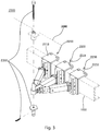
- FIG. 3 is an enlarged perspective view showing a mounting device according to a preferred embodiment of the present invention
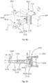
- FIG. 4(a) is a perspective view showing a supporting means according to a preferred embodiment of the present invention
- FIG. 4(b) is a sectional view taken along line A-A, showing the inside of the supporting means
- FIG. 4(c) is a plan view showing the supporting means
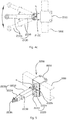
- FIG. 5 is a perspective view showing an auxiliary supporting means according to a preferred embodiment of the present invention
- FIG. 6 is a perspective view showing a coupling means according to a preferred embodiment of the present invention.
- the mounting device 2000 of the present invention is basically configured to include: a supporting means 2100 which is fastened to the chassis body 1000 shown by the dashed lines; and a coupling means 2300 which couples the supporting means 2100 and the cargo box 3000 (a load side).
- the mounting device 2000 may be configured to further include auxiliary supporting means 2200 which are mounted on the chassis body 1000 so that they are provided on the front and rear sides of the supporting means 2100 and which support the supporting means 2100.
- the auxiliary supporting means 2200 are provided to improve the supporting force of the main supporting means 2100, and it will be apparent that the auxiliary supporting means 2200 may not be provided depending on the load weight of a load, which is a load side.
- it is more advantageous to provide the auxiliary supporting means 2200 because the supporting force of the main supporting means 2100 is improved by the provision of the auxiliary supporting means 2200.
- the auxiliary supporting means 2200 will be also described.
- the supporting means 2100 is configured to include a fastening jig 2110, a vertically movable member 2120, a support member 2130, and a guide member 2140, as shown in FIGS. 4(a) to 4 (c) .
- the fastening jig 2110 is fastened to the chassis body 1000 shown by dashed lines.
- the fastening jig 2110 includes first and second jigs configured to be separable, and is firmly fastened to the chassis body 1000.
- the fastening jig 2110 may be formed in various shapes and configurations. It should be appreciated that the shape and configuration of the fastening jig 2110 are not separately limited in the present application.
- the vertically movable member 2120 includes a body 2122 which is disposed on one side surface of the fastening jig 2110, a vertically movable element 2124 which is vertically movably provided inside the body 2122, and a knob 2126 which is provided to restrain the vertically movable element 2124 from moving. As shown in FIG. 4(b) , the vertically movable element 2124 is vertically moved, and the location of the vertically movable element 2124 is fixed via the knob 2126 fastened from the body 2122.
- the support member 2130 includes a housing 2132 which is forwardly and rearwardly rotatably mounted on the vertically movable element 2124 via a hinge "h," as FIG. 4(c) , and a support lever 2134 which is provided to be selectively pulled out of and retracted into the housing 2132 in lateral directions and at an end of which is formed a vertical through hole 2136.
- fastening holes 2138 configured to restrain the pulling-out and retracting operation of the support lever 2134 be further provided on one side of the housing 2132.
- the support member 2130 has a structure via which it is vertically movable by the vertically movable element 2124 and the angle and width thereof are variable in lateral directions.
- the support lever 2134 may be implemented to be selectively pulled out and retracted in a stepwise manner, but it is not necessary to set steps in order to enable fine adjustment.
- the guide member 2140 includes a guide 2142 which is provided over the through hole 2136 of the support lever 2134, the inside of which is passed through by a hole, which has a conical shape the outer diameter of which decreases upward, and a guide cap 2144 which is attached to a side surface of the cargo box 3000 and the inner diameter of which has the same shape as the outer diameter of the guide 2142 so that it guides the cargo box 3000 through easy seating while being fitted over the outer surface of the guide 2142.
- the guide 2142 is shown as having a conical shape, it may be formed in a spherical shape, in which case it is natural that the guide cap 2144 be also formed in a shape suitable for the shape of the guide 2142.
- the reason why the guide member 2140 is provided is to allow the cargo box 3000 to be easily seated in such a manner that the centers are made to be naturally aligned with each other as long as the cargo box 3000 is seated within a predetermined range even in the case where the centers are not accurately aligned with each other when the cargo box 3000 is seated. This will be described in detail below.
- the guide 2142 and the guide cap 2144 may be disposed in reverse directions.
- the shape is a spherical shape, an advantage arises in that the coupling means 2300 can be fastened even at an oblique angle, other than in a vertical direction, as long as the fastening hole has a margin.
- the supporting means 2100 is configured such that it is movable in vertical directions and is rotatable in front and rear lengthwise directions and its length is adjustable in lateral widthwise directions so that the location where the cargo box 3000 is coupled is variable. It should be appreciated that it may be possible to flexibly deal with the shape or center of gravity of the cargo box 3000.
- the auxiliary supporting means 2200 is configured to include a fastening jig 2210, a vertically movable member 2220, and a support member 2230, as shown in FIG. 5 .
- the auxiliary supporting means 2200 may be configured to further include auxiliary support member 2240.
- the auxiliary supporting means 2200 is mounted on each of the front and rear sides of the main supporting means 2100, and plays an auxiliary role in improving supporting force.
- the auxiliary supporting means 2200 is configured to be the same as or similar to the main supporting means 2100, and performs support while being varied in the same directions.
- the auxiliary supporting means 2200 having the same configuration as the supporting means 2100 is shown as an example, the same names are used for the same components, and detailed descriptions thereof are omitted.
- the fastening jig 2210 is provided to be fastened to the chassis body 1000 shown by the dashed lines.
- the vertically movable member 2220 is configured to include a body 2222 which is disposed on one side surface of the fastening jig 2210, a vertically movable element 2224 which is vertically movably contained inside the body 2222, and a knob 2226 which is configured to restrain the movement of the vertically movable element 2224 from the body 2222.
- the support member 2230 includes a housing 2232 which is forwardly and rearwardly rotatably mounted on the vertically movable element 2224 via a hinge "h," and a support lever 2234 which is provided to be selectively pulled out of and retracted into the housing 2232 in lateral directions and at an end of which is provided a bracket 2236 configured to be fastened to an end of the support lever 2134 of the main supporting means 2100.
- fastening holes 2238 configured to restrain the operation of selectively pulling out and retracting the support lever 2234 be further provided on one side of the housing 2232.
- the auxiliary supporting means 2200 described above have the same configuration as the main supporting means 2100 except that the auxiliary supporting means 2200 and the main supporting means 2100 are different in that the bracket 2236 is provided at an end of the support lever 2234. It is natural that the bracket 2236 be provided in the state of being rotatable via a pin which is not denoted by a reference symbol. As a result, the auxiliary supporting means 2200 enables continuous support while being variable in accordance with the variable direction of the main supporting means 2100.
- a configuration which is the same as the supporting means 2100 may be mounted on the cargo box 3000.
- a conical (tapered) or spherical auxiliary guide member having the same configuration as the guide member 2140 is provided at each of the corners of the chassis and the cargo box, which is a load side, when the cargo box is seated, the auxiliary guide members are coupled first and then guide the cargo box thorough seating, thereby providing convenience. It is obvious that each of them may be formed into male and female forms.
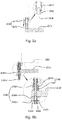
- the coupling means 2300 is configured to include: a bolt rod 2310 which is mounted downward from a location above the guide cap attached to the side surface of the cargo box 3000 and on one side of which is formed an insertion hole 2312 that passes through the bolt rod 2310 in a lateral direction; a nut member 2320 which is located below the support lever 2134 of the supporting means 2100 and screwed over the bolt rod 2310 protruding through the through hole 2136 downward, through one side surface of which is formed a coupling hole 2322 passing through the nut member 2320 in a lateral direction, and on the outer circumference of the upper side of which is formed a large nut portion 2324 and on the outer circumference of the lower side of which is formed a small nut portion 2326; and a fastening pin 2330 which prevents a phenomenon in which the nut member 2320 is released by sequentially passing through the coupling hole 2322 and the insertion hole 2312 of the bolt rod 2310 through the side surfaces of
- the vertical insertion hole 2312 formed in the bolt rod 2310 is formed for the correction of the fastening stroke of the nut member.
- the coupling of the coupling means 2300 will be described again below.
- FIG. 7 is a schematic plan view showing the variation operation of a supporting means and auxiliary supporting means according to a preferred embodiment of the present invention
- FIG. 8(a) is a schematic longitudinal sectional view showing a process in which a cargo box is seated according to a preferred embodiment of the present invention
- FIG. 8(b) is a schematic longitudinal sectional view showing the coupling of a coupling means.
- the support member 2130 of the supporting means 2100 is forwardly and rearwardly rotated via the hinge h and simultaneously the support lever 2134 is pulled out.
- the support members 2230 of the auxiliary supporting means 2200 which support the support lever 2134 on front and rear sides are also forwardly and rearwardly rotated, and thus are varied in accordance with the location of the main supporting means 2100 and provide stable support even when the location of the main supporting means 2100 is varied due to the pulling-out operation of the support lever 2234.
- the supporting means 2100 is movable in vertical directions via the vertically movable member 2120 and the auxiliary supporting means 2200 are also variable via the vertically movable members 2220 in conjunction with the vertical movement operation of the main supporting means 2100.
- the above description means that as the supporting means 2100 and the auxiliary supporting means 2200 are variable, an operator may easily vary a coupling location as desired according to the shape or center of gravity of the cargo box 3000 to be seated. It should be understood that this also means that only a specific cargo box or specific special equipment is not coupled but most cargo boxes or special equipment may be coupled.
- the guide 2142 is provided at an end of the support lever 2134, and the guide cap 2144 which is coupled onto the outer surface of the guide 2142 is provided on a side surface of the cargo box 3000.
- the bolt rod 2310 is coupled downward from a location above the guide cap 2144 of the guide member 2140, the nut member 2320 is tightened on the bolt rod 2310 protruding downward from the main support lever 2134, and the fastening pin 2330 is inserted in a lateral direction, sequentially passes through the coupling hole 2322 of the nut member 2320 and the insertion hole 2312 of the bolt rod 2310, and performs fastening. This prevents the nut member 2320 from being freely rotated.
- the nut member 2320 is provided with the large nut portion 2324 and the small nut portion 2326 on the upper and lower sides thereof.
- the reason for this is to rotate the nut member 2320 with a tool via the large nut portion 2324 when an emergency occurs while enabling the nut member 2320 to be fastened without a separate tool via the small nut portion 2326.
- the small nut portion 2326 is temporarily fastened using a small torque upon initial no-load mounting, and then comes into a firm close contact as upside and downside loads increase when a load is loaded or a work load is applied.
- the small nut portion 2326 is configured to be more firmly fastened by re-tightening the small nut portion 2326 with a small tool when a load is applied, and, thus, is a means which completely and simply fastens the chassis body 1000 and a loading part to each other.
- a handle may be attached in place of the small nut portion 2326, and may be configured to be easily rotated by a hand. It should be appreciated that this is a variation of the present application.
- the reason why the large nut portion 2324 is formed on the nut member 2320 is to provide a means for selectively loosening and tightening the nut member 2320 with a large torque in a no load state or when a fastening or unfastening operation is required in an emergency.
- damage may occur due to a structural reason or it is difficult to perform work using a large torque.
- a conventionally known coupling means such as a U bolt or I bolt
- a coupling means 2300 of the present invention which may stably fasten all various types of cargo boxes or special equipment without being limited to any one type of cargo box or special equipment and provide excellent coupling force, thereby preventing the occurrence of a clearance.
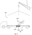
- FIG. 9 is a schematic side view showing a process in which a cargo box is seated according to a preferred embodiment of the present invention
- FIGS. 10(a) to 10(c) are schematic side views showing cases where various types of cargo boxes or special equipment are seated according to preferred embodiments of the present invention.
- a passenger car body 3100 capable of carrying people like a passenger car or passenger van may be loaded, as shown in FIG. 10(a)
- tank truck special equipment 3200 may be loaded, as shown in FIG. 10(b)
- machinery special equipment 3300 such as a crane, may be loaded, as shown in FIG. 10(c) .
Landscapes
- Engineering & Computer Science (AREA)
- Mechanical Engineering (AREA)
- Transportation (AREA)
- Chemical & Material Sciences (AREA)
- Combustion & Propulsion (AREA)
- Health & Medical Sciences (AREA)
- Public Health (AREA)
- Life Sciences & Earth Sciences (AREA)
- Agronomy & Crop Science (AREA)
- Body Structure For Vehicles (AREA)
- Fittings On The Vehicle Exterior For Carrying Loads, And Devices For Holding Or Mounting Articles (AREA)
Applications Claiming Priority (2)
| Application Number | Priority Date | Filing Date | Title |
|---|---|---|---|
| KR1020170037082A KR101903885B1 (ko) | 2017-03-23 | 2017-03-23 | 자동차 바디 및 각종 특장장치를 적재물화 한 자동차 샤시 |
| PCT/KR2018/001866 WO2018174410A1 (ko) | 2017-03-23 | 2018-02-13 | 자동차 바디 및 각종 특장장치를 적재물화 한 자동차 샤시 |
Publications (3)
| Publication Number | Publication Date |
|---|---|
| EP3604084A1 true EP3604084A1 (de) | 2020-02-05 |
| EP3604084A4 EP3604084A4 (de) | 2020-03-18 |
| EP3604084B1 EP3604084B1 (de) | 2022-01-12 |
Family
ID=63585503
Family Applications (1)
| Application Number | Title | Priority Date | Filing Date |
|---|---|---|---|
| EP18770709.6A Not-in-force EP3604084B1 (de) | 2017-03-23 | 2018-02-13 | Fahrgestell zum tragen von automobilkarosserien und verschiedene spezifisch ausgestattete vorrichtungen als lasten |
Country Status (10)
| Country | Link |
|---|---|
| US (1) | US11052814B2 (de) |
| EP (1) | EP3604084B1 (de) |
| JP (1) | JP6803995B2 (de) |
| KR (1) | KR101903885B1 (de) |
| CN (1) | CN110191837B (de) |
| BR (1) | BR112019019500A2 (de) |
| CA (1) | CA3056385C (de) |
| PH (1) | PH12019501619A1 (de) |
| RU (1) | RU2719073C1 (de) |
| WO (1) | WO2018174410A1 (de) |
Families Citing this family (8)
| Publication number | Priority date | Publication date | Assignee | Title |
|---|---|---|---|---|
| EP3600968B1 (de) * | 2017-03-31 | 2021-01-20 | Volvo Truck Corporation | Fahrzeugbaugruppe und verfahren |
| CN113022414A (zh) * | 2021-03-16 | 2021-06-25 | 广东电网有限责任公司佛山供电局 | 一种输电塔抢修卡车 |
| CN113060226B (zh) * | 2021-03-31 | 2023-07-21 | 赵桐 | 用于土地资源管理的取样车装置和使用方法 |
| CN113232579B (zh) * | 2021-04-02 | 2024-05-14 | 徐州徐工养护机械有限公司 | 一种方舱运输车 |
| CN113212525B (zh) * | 2021-06-04 | 2022-08-30 | 四川航天长征装备制造有限公司 | 一种多功能对接架车 |
| CN115818462A (zh) * | 2022-11-29 | 2023-03-21 | 杭州国电机械设计研究院有限公司 | 一种升船机主机大件吊装设备 |
| EP4484216B1 (de) * | 2023-06-27 | 2026-05-06 | Pongratz Trailer-Group GmbH | Anhänger zum transportieren von containern |
| KR102865610B1 (ko) | 2023-09-22 | 2025-09-30 | 서진산업 주식회사 | 목적기반 모빌리티 적재함 교체구조 및 교체방법 |
Family Cites Families (26)
| Publication number | Priority date | Publication date | Assignee | Title |
|---|---|---|---|---|
| US1860747A (en) * | 1931-01-26 | 1932-05-31 | Thomas L Mclaughlin | Transportation device |
| US3259400A (en) * | 1964-04-01 | 1966-07-05 | Fruehauf Corp | Semi-trailer apparatus for vehicu-larizing containers |
| US4341204A (en) * | 1978-10-30 | 1982-07-27 | Bloxsom Dan E | Solar energy collector |
| JPS57124442U (de) * | 1981-01-29 | 1982-08-03 | ||
| JPH0781477A (ja) | 1993-09-09 | 1995-03-28 | Mitsubishi Automob Eng Co Ltd | コンテナ積載用車両 |
| JP3743776B2 (ja) * | 1995-04-07 | 2006-02-08 | 近藤 多喜男 | コンテナーの据置構造 |
| KR200198919Y1 (ko) | 1998-04-24 | 2000-10-02 | 서재국 | 컨테이너 적재용 트레일러샤시 |
| DE20012977U1 (de) * | 2000-07-27 | 2001-02-08 | R. Metternich Metallbau GmbH, 21107 Hamburg | Vorrichtung zur Befestigung eines überlangen Containers auf einem Transportfahrzeug |
| FI112191B (fi) * | 2000-12-12 | 2003-11-14 | Tauno Kulojaervi | Ajoneuvon runko ja kiinnityskappale runkopalkkien yhteenliittämistä varten |
| NL1019712C1 (nl) * | 2002-01-08 | 2003-07-09 | Broshuis B V | Universele containervergrendeling. |
| US7004697B2 (en) * | 2002-03-29 | 2006-02-28 | United States Of America As Represented By The Secretary Of The Army | Outrigger lifting device for fuel tankers |
| ES2228215B1 (es) * | 2002-06-28 | 2006-06-01 | Schulz Iberica, S.A. | Esquina de amarre polivalente modular para chasis porta-contenedores. |
| JP3906160B2 (ja) | 2003-01-30 | 2007-04-18 | 日野自動車株式会社 | 荷台締結構造 |
| GB2409852B (en) * | 2004-01-06 | 2007-08-15 | Paul Anthony Raven | Trailers for carrying containerised loads |
| DE102004045665B4 (de) * | 2004-09-18 | 2008-01-31 | Jost-Werke Gmbh & Co. Kg | Querträger zum stirnseitigen Einbau in ein Chassis |
| JP3114945U (ja) * | 2005-07-21 | 2005-10-27 | 株式会社横急運輸 | トラック車両 |
| RU2303545C1 (ru) * | 2006-03-13 | 2007-07-27 | Владимир Александрович Белобородов | Устройство для крепления передней, в основном, части кузова на раме транспортного средства |
| CN201026918Y (zh) * | 2006-12-30 | 2008-02-27 | 方毅 | 一种可更换厢体的多用途特种专用车 |
| JP5337118B2 (ja) | 2010-09-03 | 2013-11-06 | 株式会社守隨本店 | 車両搭載型計重装置 |
| JP5386571B2 (ja) | 2011-11-11 | 2014-01-15 | 耕二 二村 | 貨物車の積載物重量測定装置 |
| KR20130100576A (ko) | 2012-03-02 | 2013-09-11 | (주)유성티엔에스 | 화물열차의 컨테이너 고정용 어댑터 |
| NL2008619C2 (nl) * | 2012-04-10 | 2013-10-15 | Vlastuin Group B V | Verschuifbare koppelbalk en trailer met verschuifbare koppelbalk. |
| EP2765029A1 (de) * | 2013-02-08 | 2014-08-13 | HFM Patenten BV | Anhänger zur Verwendung im Straßengüterverkehr und Verfahren zur Verwendung des Anhängers |
| DE102013202839A1 (de) * | 2013-02-21 | 2014-08-21 | Jörg Zoller | Wechselrahmen für Fahrzeugaufbauten |
| US9586631B2 (en) * | 2014-06-30 | 2017-03-07 | Ford Global Technologies, Llc | Cast load structure for vehicle body to frame mount |
| GB201515568D0 (en) * | 2015-09-02 | 2015-10-14 | Dennsion Trailers Ltd | A Semi-Trailer |
-
2017
- 2017-03-23 KR KR1020170037082A patent/KR101903885B1/ko active Active
-
2018
- 2018-02-13 EP EP18770709.6A patent/EP3604084B1/de not_active Not-in-force
- 2018-02-13 WO PCT/KR2018/001866 patent/WO2018174410A1/ko not_active Ceased
- 2018-02-13 JP JP2019560622A patent/JP6803995B2/ja not_active Expired - Fee Related
- 2018-02-13 RU RU2019121580A patent/RU2719073C1/ru active
- 2018-02-13 CN CN201880007378.0A patent/CN110191837B/zh not_active Expired - Fee Related
- 2018-02-13 US US16/477,254 patent/US11052814B2/en not_active Expired - Fee Related
- 2018-02-13 BR BR112019019500A patent/BR112019019500A2/pt not_active IP Right Cessation
- 2018-02-13 CA CA3056385A patent/CA3056385C/en active Active
-
2019
- 2019-07-11 PH PH12019501619A patent/PH12019501619A1/en unknown
Also Published As
| Publication number | Publication date |
|---|---|
| US20190351812A1 (en) | 2019-11-21 |
| JP2020505273A (ja) | 2020-02-20 |
| EP3604084A4 (de) | 2020-03-18 |
| US11052814B2 (en) | 2021-07-06 |
| CN110191837B (zh) | 2021-09-21 |
| JP6803995B2 (ja) | 2020-12-23 |
| BR112019019500A2 (pt) | 2020-04-28 |
| PH12019501619A1 (en) | 2020-03-16 |
| CA3056385A1 (en) | 2018-09-27 |
| EP3604084B1 (de) | 2022-01-12 |
| CA3056385C (en) | 2023-03-21 |
| KR101903885B1 (ko) | 2018-10-02 |
| CN110191837A (zh) | 2019-08-30 |
| WO2018174410A1 (ko) | 2018-09-27 |
| RU2719073C1 (ru) | 2020-04-17 |
Similar Documents
| Publication | Publication Date | Title |
|---|---|---|
| US11052814B2 (en) | Automobile chassis for carrying automobile body and various specially-equipped devices as loads | |
| US6158761A (en) | Accessory mounting apparatus for a pickup truck | |
| US8720760B1 (en) | Heavy duty, leveraged spare tire carrier | |
| US9145176B1 (en) | Vehicle box reinforcing brace | |
| US8840000B1 (en) | Heavy duty leveraged spare tire carrier | |
| US7121574B2 (en) | Pin box assembly having interchangeable hitch couplers | |
| DE102019107333B4 (de) | Sonderfahrzeug | |
| US11752816B2 (en) | Trailer hitch assembly | |
| CH703885A2 (de) | Fahrzeug. | |
| CN100545001C (zh) | 重型加长挂车刮板式自卸装置 | |
| CN219007681U (zh) | 一种集装箱自卸车 | |
| CN201825112U (zh) | 兼有工具箱功能的重型载货汽车车架后横梁 | |
| EP2493747B1 (de) | Stützrahmen für einen anhänger | |
| CN219339298U (zh) | 一种多功能车载内置斜坡 | |
| CN206436882U (zh) | 自卸半挂车 | |
| CN205769574U (zh) | 一种多功能车辆的底盘系统 | |
| DE202019101642U1 (de) | Sonderfahrzeug | |
| CN220518422U (zh) | 一种厢式货车中央隔墙结构 | |
| US12479349B2 (en) | Multideck trailer | |
| JP3235799U (ja) | トレーラーおよび連結車両 | |
| EP1801001B1 (de) | Aufbau für einen Anhänger eines Lastkraftwagens und Anhänger eines Lastkraftwagens | |
| DE102012009894A1 (de) | Anhänger für ein Nutzfahrzeug | |
| EP2709856A1 (de) | Lastenträger | |
| CN201009942Y (zh) | 汽车货箱翻转架 | |
| CN201525427U (zh) | 一种自卸车及其备胎的固定装置 |
Legal Events
| Date | Code | Title | Description |
|---|---|---|---|
| STAA | Information on the status of an ep patent application or granted ep patent |
Free format text: STATUS: THE INTERNATIONAL PUBLICATION HAS BEEN MADE |
|
| PUAI | Public reference made under article 153(3) epc to a published international application that has entered the european phase |
Free format text: ORIGINAL CODE: 0009012 |
|
| STAA | Information on the status of an ep patent application or granted ep patent |
Free format text: STATUS: REQUEST FOR EXAMINATION WAS MADE |
|
| 17P | Request for examination filed |
Effective date: 20190723 |
|
| AK | Designated contracting states |
Kind code of ref document: A1 Designated state(s): AL AT BE BG CH CY CZ DE DK EE ES FI FR GB GR HR HU IE IS IT LI LT LU LV MC MK MT NL NO PL PT RO RS SE SI SK SM TR |
|
| AX | Request for extension of the european patent |
Extension state: BA ME |
|
| A4 | Supplementary search report drawn up and despatched |
Effective date: 20200217 |
|
| RIC1 | Information provided on ipc code assigned before grant |
Ipc: B60P 3/00 20060101ALI20200211BHEP Ipc: B62D 63/02 20060101ALI20200211BHEP Ipc: B62D 24/00 20060101AFI20200211BHEP Ipc: B62D 21/09 20060101ALI20200211BHEP Ipc: B66C 23/44 20060101ALI20200211BHEP |
|
| DAV | Request for validation of the european patent (deleted) | ||
| DAX | Request for extension of the european patent (deleted) | ||
| GRAP | Despatch of communication of intention to grant a patent |
Free format text: ORIGINAL CODE: EPIDOSNIGR1 |
|
| STAA | Information on the status of an ep patent application or granted ep patent |
Free format text: STATUS: GRANT OF PATENT IS INTENDED |
|
| INTG | Intention to grant announced |
Effective date: 20210906 |
|
| GRAS | Grant fee paid |
Free format text: ORIGINAL CODE: EPIDOSNIGR3 |
|
| GRAA | (expected) grant |
Free format text: ORIGINAL CODE: 0009210 |
|
| STAA | Information on the status of an ep patent application or granted ep patent |
Free format text: STATUS: THE PATENT HAS BEEN GRANTED |
|
| AK | Designated contracting states |
Kind code of ref document: B1 Designated state(s): AL AT BE BG CH CY CZ DE DK EE ES FI FR GB GR HR HU IE IS IT LI LT LU LV MC MK MT NL NO PL PT RO RS SE SI SK SM TR |
|
| REG | Reference to a national code |
Ref country code: GB Ref legal event code: FG4D |
|
| REG | Reference to a national code |
Ref country code: CH Ref legal event code: EP |
|
| REG | Reference to a national code |
Ref country code: DE Ref legal event code: R096 Ref document number: 602018029560 Country of ref document: DE |
|
| REG | Reference to a national code |
Ref country code: IE Ref legal event code: FG4D |
|
| REG | Reference to a national code |
Ref country code: AT Ref legal event code: REF Ref document number: 1462189 Country of ref document: AT Kind code of ref document: T Effective date: 20220215 |
|
| REG | Reference to a national code |
Ref country code: NL Ref legal event code: FP |
|
| REG | Reference to a national code |
Ref country code: LT Ref legal event code: MG9D |
|
| REG | Reference to a national code |
Ref country code: AT Ref legal event code: MK05 Ref document number: 1462189 Country of ref document: AT Kind code of ref document: T Effective date: 20220112 |
|
| PG25 | Lapsed in a contracting state [announced via postgrant information from national office to epo] |
Ref country code: SE Free format text: LAPSE BECAUSE OF FAILURE TO SUBMIT A TRANSLATION OF THE DESCRIPTION OR TO PAY THE FEE WITHIN THE PRESCRIBED TIME-LIMIT Effective date: 20220112 Ref country code: RS Free format text: LAPSE BECAUSE OF FAILURE TO SUBMIT A TRANSLATION OF THE DESCRIPTION OR TO PAY THE FEE WITHIN THE PRESCRIBED TIME-LIMIT Effective date: 20220112 Ref country code: PT Free format text: LAPSE BECAUSE OF FAILURE TO SUBMIT A TRANSLATION OF THE DESCRIPTION OR TO PAY THE FEE WITHIN THE PRESCRIBED TIME-LIMIT Effective date: 20220512 Ref country code: NO Free format text: LAPSE BECAUSE OF FAILURE TO SUBMIT A TRANSLATION OF THE DESCRIPTION OR TO PAY THE FEE WITHIN THE PRESCRIBED TIME-LIMIT Effective date: 20220412 Ref country code: LT Free format text: LAPSE BECAUSE OF FAILURE TO SUBMIT A TRANSLATION OF THE DESCRIPTION OR TO PAY THE FEE WITHIN THE PRESCRIBED TIME-LIMIT Effective date: 20220112 Ref country code: HR Free format text: LAPSE BECAUSE OF FAILURE TO SUBMIT A TRANSLATION OF THE DESCRIPTION OR TO PAY THE FEE WITHIN THE PRESCRIBED TIME-LIMIT Effective date: 20220112 Ref country code: ES Free format text: LAPSE BECAUSE OF FAILURE TO SUBMIT A TRANSLATION OF THE DESCRIPTION OR TO PAY THE FEE WITHIN THE PRESCRIBED TIME-LIMIT Effective date: 20220112 Ref country code: BG Free format text: LAPSE BECAUSE OF FAILURE TO SUBMIT A TRANSLATION OF THE DESCRIPTION OR TO PAY THE FEE WITHIN THE PRESCRIBED TIME-LIMIT Effective date: 20220412 |
|
| PG25 | Lapsed in a contracting state [announced via postgrant information from national office to epo] |
Ref country code: PL Free format text: LAPSE BECAUSE OF FAILURE TO SUBMIT A TRANSLATION OF THE DESCRIPTION OR TO PAY THE FEE WITHIN THE PRESCRIBED TIME-LIMIT Effective date: 20220112 Ref country code: LV Free format text: LAPSE BECAUSE OF FAILURE TO SUBMIT A TRANSLATION OF THE DESCRIPTION OR TO PAY THE FEE WITHIN THE PRESCRIBED TIME-LIMIT Effective date: 20220112 Ref country code: GR Free format text: LAPSE BECAUSE OF FAILURE TO SUBMIT A TRANSLATION OF THE DESCRIPTION OR TO PAY THE FEE WITHIN THE PRESCRIBED TIME-LIMIT Effective date: 20220413 Ref country code: FI Free format text: LAPSE BECAUSE OF FAILURE TO SUBMIT A TRANSLATION OF THE DESCRIPTION OR TO PAY THE FEE WITHIN THE PRESCRIBED TIME-LIMIT Effective date: 20220112 Ref country code: AT Free format text: LAPSE BECAUSE OF FAILURE TO SUBMIT A TRANSLATION OF THE DESCRIPTION OR TO PAY THE FEE WITHIN THE PRESCRIBED TIME-LIMIT Effective date: 20220112 |
|
| PG25 | Lapsed in a contracting state [announced via postgrant information from national office to epo] |
Ref country code: IS Free format text: LAPSE BECAUSE OF FAILURE TO SUBMIT A TRANSLATION OF THE DESCRIPTION OR TO PAY THE FEE WITHIN THE PRESCRIBED TIME-LIMIT Effective date: 20220512 |
|
| REG | Reference to a national code |
Ref country code: DE Ref legal event code: R097 Ref document number: 602018029560 Country of ref document: DE |
|
| REG | Reference to a national code |
Ref country code: CH Ref legal event code: PL |
|
| REG | Reference to a national code |
Ref country code: BE Ref legal event code: MM Effective date: 20220228 |
|
| PG25 | Lapsed in a contracting state [announced via postgrant information from national office to epo] |
Ref country code: SM Free format text: LAPSE BECAUSE OF FAILURE TO SUBMIT A TRANSLATION OF THE DESCRIPTION OR TO PAY THE FEE WITHIN THE PRESCRIBED TIME-LIMIT Effective date: 20220112 Ref country code: SK Free format text: LAPSE BECAUSE OF FAILURE TO SUBMIT A TRANSLATION OF THE DESCRIPTION OR TO PAY THE FEE WITHIN THE PRESCRIBED TIME-LIMIT Effective date: 20220112 Ref country code: RO Free format text: LAPSE BECAUSE OF FAILURE TO SUBMIT A TRANSLATION OF THE DESCRIPTION OR TO PAY THE FEE WITHIN THE PRESCRIBED TIME-LIMIT Effective date: 20220112 Ref country code: MC Free format text: LAPSE BECAUSE OF FAILURE TO SUBMIT A TRANSLATION OF THE DESCRIPTION OR TO PAY THE FEE WITHIN THE PRESCRIBED TIME-LIMIT Effective date: 20220112 Ref country code: LU Free format text: LAPSE BECAUSE OF NON-PAYMENT OF DUE FEES Effective date: 20220213 Ref country code: EE Free format text: LAPSE BECAUSE OF FAILURE TO SUBMIT A TRANSLATION OF THE DESCRIPTION OR TO PAY THE FEE WITHIN THE PRESCRIBED TIME-LIMIT Effective date: 20220112 Ref country code: DK Free format text: LAPSE BECAUSE OF FAILURE TO SUBMIT A TRANSLATION OF THE DESCRIPTION OR TO PAY THE FEE WITHIN THE PRESCRIBED TIME-LIMIT Effective date: 20220112 Ref country code: CZ Free format text: LAPSE BECAUSE OF FAILURE TO SUBMIT A TRANSLATION OF THE DESCRIPTION OR TO PAY THE FEE WITHIN THE PRESCRIBED TIME-LIMIT Effective date: 20220112 |
|
| PLBE | No opposition filed within time limit |
Free format text: ORIGINAL CODE: 0009261 |
|
| STAA | Information on the status of an ep patent application or granted ep patent |
Free format text: STATUS: NO OPPOSITION FILED WITHIN TIME LIMIT |
|
| PG25 | Lapsed in a contracting state [announced via postgrant information from national office to epo] |
Ref country code: AL Free format text: LAPSE BECAUSE OF FAILURE TO SUBMIT A TRANSLATION OF THE DESCRIPTION OR TO PAY THE FEE WITHIN THE PRESCRIBED TIME-LIMIT Effective date: 20220112 |
|
| 26N | No opposition filed |
Effective date: 20221013 |
|
| PG25 | Lapsed in a contracting state [announced via postgrant information from national office to epo] |
Ref country code: LI Free format text: LAPSE BECAUSE OF NON-PAYMENT OF DUE FEES Effective date: 20220228 Ref country code: IE Free format text: LAPSE BECAUSE OF NON-PAYMENT OF DUE FEES Effective date: 20220213 Ref country code: CH Free format text: LAPSE BECAUSE OF NON-PAYMENT OF DUE FEES Effective date: 20220228 |
|
| PG25 | Lapsed in a contracting state [announced via postgrant information from national office to epo] |
Ref country code: SI Free format text: LAPSE BECAUSE OF FAILURE TO SUBMIT A TRANSLATION OF THE DESCRIPTION OR TO PAY THE FEE WITHIN THE PRESCRIBED TIME-LIMIT Effective date: 20220112 Ref country code: BE Free format text: LAPSE BECAUSE OF NON-PAYMENT OF DUE FEES Effective date: 20220228 |
|
| PGFP | Annual fee paid to national office [announced via postgrant information from national office to epo] |
Ref country code: NL Payment date: 20240220 Year of fee payment: 7 |
|
| PG25 | Lapsed in a contracting state [announced via postgrant information from national office to epo] |
Ref country code: MK Free format text: LAPSE BECAUSE OF FAILURE TO SUBMIT A TRANSLATION OF THE DESCRIPTION OR TO PAY THE FEE WITHIN THE PRESCRIBED TIME-LIMIT Effective date: 20220112 Ref country code: CY Free format text: LAPSE BECAUSE OF FAILURE TO SUBMIT A TRANSLATION OF THE DESCRIPTION OR TO PAY THE FEE WITHIN THE PRESCRIBED TIME-LIMIT Effective date: 20220112 |
|
| PGFP | Annual fee paid to national office [announced via postgrant information from national office to epo] |
Ref country code: DE Payment date: 20240221 Year of fee payment: 7 Ref country code: GB Payment date: 20240219 Year of fee payment: 7 |
|
| PG25 | Lapsed in a contracting state [announced via postgrant information from national office to epo] |
Ref country code: HU Free format text: LAPSE BECAUSE OF FAILURE TO SUBMIT A TRANSLATION OF THE DESCRIPTION OR TO PAY THE FEE WITHIN THE PRESCRIBED TIME-LIMIT; INVALID AB INITIO Effective date: 20180213 |
|
| PGFP | Annual fee paid to national office [announced via postgrant information from national office to epo] |
Ref country code: IT Payment date: 20240220 Year of fee payment: 7 Ref country code: FR Payment date: 20240219 Year of fee payment: 7 |
|
| PG25 | Lapsed in a contracting state [announced via postgrant information from national office to epo] |
Ref country code: MT Free format text: LAPSE BECAUSE OF FAILURE TO SUBMIT A TRANSLATION OF THE DESCRIPTION OR TO PAY THE FEE WITHIN THE PRESCRIBED TIME-LIMIT Effective date: 20220112 |
|
| REG | Reference to a national code |
Ref country code: DE Ref legal event code: R119 Ref document number: 602018029560 Country of ref document: DE |
|
| REG | Reference to a national code |
Ref country code: NL Ref legal event code: MM Effective date: 20250301 |
|
| GBPC | Gb: european patent ceased through non-payment of renewal fee |
Effective date: 20250213 |
|
| PG25 | Lapsed in a contracting state [announced via postgrant information from national office to epo] |
Ref country code: NL Free format text: LAPSE BECAUSE OF NON-PAYMENT OF DUE FEES Effective date: 20250301 |
|
| PG25 | Lapsed in a contracting state [announced via postgrant information from national office to epo] |
Ref country code: TR Free format text: LAPSE BECAUSE OF FAILURE TO SUBMIT A TRANSLATION OF THE DESCRIPTION OR TO PAY THE FEE WITHIN THE PRESCRIBED TIME-LIMIT Effective date: 20220112 |
|
| PG25 | Lapsed in a contracting state [announced via postgrant information from national office to epo] |
Ref country code: DE Free format text: LAPSE BECAUSE OF NON-PAYMENT OF DUE FEES Effective date: 20250902 |
|
| PG25 | Lapsed in a contracting state [announced via postgrant information from national office to epo] |
Ref country code: GB Free format text: LAPSE BECAUSE OF NON-PAYMENT OF DUE FEES Effective date: 20250213 |
|
| PG25 | Lapsed in a contracting state [announced via postgrant information from national office to epo] |
Ref country code: IT Free format text: LAPSE BECAUSE OF NON-PAYMENT OF DUE FEES Effective date: 20250213 Ref country code: FR Free format text: LAPSE BECAUSE OF NON-PAYMENT OF DUE FEES Effective date: 20250228 |