EP3604069B1 - Fahrgeschwindigkeitssteuerungsverfahren, vorrichtung, computervorrichtung und speichermedium - Google Patents
Fahrgeschwindigkeitssteuerungsverfahren, vorrichtung, computervorrichtung und speichermedium Download PDFInfo
- Publication number
- EP3604069B1 EP3604069B1 EP18847584.2A EP18847584A EP3604069B1 EP 3604069 B1 EP3604069 B1 EP 3604069B1 EP 18847584 A EP18847584 A EP 18847584A EP 3604069 B1 EP3604069 B1 EP 3604069B1
- Authority
- EP
- European Patent Office
- Prior art keywords
- curvature
- target
- sampling
- current
- sampling point
- Prior art date
- Legal status (The legal status is an assumption and is not a legal conclusion. Google has not performed a legal analysis and makes no representation as to the accuracy of the status listed.)
- Active
Links
Images



Classifications
-
- B—PERFORMING OPERATIONS; TRANSPORTING
- B60—VEHICLES IN GENERAL
- B60W—CONJOINT CONTROL OF VEHICLE SUB-UNITS OF DIFFERENT TYPE OR DIFFERENT FUNCTION; CONTROL SYSTEMS SPECIALLY ADAPTED FOR HYBRID VEHICLES; ROAD VEHICLE DRIVE CONTROL SYSTEMS FOR PURPOSES NOT RELATED TO THE CONTROL OF A PARTICULAR SUB-UNIT
- B60W50/00—Details of control systems for road vehicle drive control not related to the control of a particular sub-unit, e.g. process diagnostic or vehicle driver interfaces
-
- B—PERFORMING OPERATIONS; TRANSPORTING
- B60—VEHICLES IN GENERAL
- B60W—CONJOINT CONTROL OF VEHICLE SUB-UNITS OF DIFFERENT TYPE OR DIFFERENT FUNCTION; CONTROL SYSTEMS SPECIALLY ADAPTED FOR HYBRID VEHICLES; ROAD VEHICLE DRIVE CONTROL SYSTEMS FOR PURPOSES NOT RELATED TO THE CONTROL OF A PARTICULAR SUB-UNIT
- B60W30/00—Purposes of road vehicle drive control systems not related to the control of a particular sub-unit, e.g. of systems using conjoint control of vehicle sub-units
- B60W30/14—Adaptive cruise control
- B60W30/143—Speed control
-
- B—PERFORMING OPERATIONS; TRANSPORTING
- B60—VEHICLES IN GENERAL
- B60W—CONJOINT CONTROL OF VEHICLE SUB-UNITS OF DIFFERENT TYPE OR DIFFERENT FUNCTION; CONTROL SYSTEMS SPECIALLY ADAPTED FOR HYBRID VEHICLES; ROAD VEHICLE DRIVE CONTROL SYSTEMS FOR PURPOSES NOT RELATED TO THE CONTROL OF A PARTICULAR SUB-UNIT
- B60W30/00—Purposes of road vehicle drive control systems not related to the control of a particular sub-unit, e.g. of systems using conjoint control of vehicle sub-units
- B60W30/18—Propelling the vehicle
-
- B—PERFORMING OPERATIONS; TRANSPORTING
- B60—VEHICLES IN GENERAL
- B60K—ARRANGEMENT OR MOUNTING OF PROPULSION UNITS OR OF TRANSMISSIONS IN VEHICLES; ARRANGEMENT OR MOUNTING OF PLURAL DIVERSE PRIME-MOVERS IN VEHICLES; AUXILIARY DRIVES FOR VEHICLES; INSTRUMENTATION OR DASHBOARDS FOR VEHICLES; ARRANGEMENTS IN CONNECTION WITH COOLING, AIR INTAKE, GAS EXHAUST OR FUEL SUPPLY OF PROPULSION UNITS IN VEHICLES
- B60K31/00—Vehicle fittings, acting on a single sub-unit only, for automatically controlling vehicle speed, i.e. preventing speed from exceeding an arbitrarily established velocity or maintaining speed at a particular velocity, as selected by the vehicle operator
-
- B—PERFORMING OPERATIONS; TRANSPORTING
- B60—VEHICLES IN GENERAL
- B60W—CONJOINT CONTROL OF VEHICLE SUB-UNITS OF DIFFERENT TYPE OR DIFFERENT FUNCTION; CONTROL SYSTEMS SPECIALLY ADAPTED FOR HYBRID VEHICLES; ROAD VEHICLE DRIVE CONTROL SYSTEMS FOR PURPOSES NOT RELATED TO THE CONTROL OF A PARTICULAR SUB-UNIT
- B60W30/00—Purposes of road vehicle drive control systems not related to the control of a particular sub-unit, e.g. of systems using conjoint control of vehicle sub-units
- B60W30/08—Active safety systems predicting or avoiding probable or impending collision or attempting to minimise its consequences
- B60W30/095—Predicting travel path or likelihood of collision
- B60W30/0956—Predicting travel path or likelihood of collision the prediction being responsive to traffic or environmental parameters
-
- B—PERFORMING OPERATIONS; TRANSPORTING
- B60—VEHICLES IN GENERAL
- B60W—CONJOINT CONTROL OF VEHICLE SUB-UNITS OF DIFFERENT TYPE OR DIFFERENT FUNCTION; CONTROL SYSTEMS SPECIALLY ADAPTED FOR HYBRID VEHICLES; ROAD VEHICLE DRIVE CONTROL SYSTEMS FOR PURPOSES NOT RELATED TO THE CONTROL OF A PARTICULAR SUB-UNIT
- B60W30/00—Purposes of road vehicle drive control systems not related to the control of a particular sub-unit, e.g. of systems using conjoint control of vehicle sub-units
- B60W30/18—Propelling the vehicle
- B60W30/18009—Propelling the vehicle related to particular drive situations
- B60W30/18145—Cornering
-
- B—PERFORMING OPERATIONS; TRANSPORTING
- B60—VEHICLES IN GENERAL
- B60W—CONJOINT CONTROL OF VEHICLE SUB-UNITS OF DIFFERENT TYPE OR DIFFERENT FUNCTION; CONTROL SYSTEMS SPECIALLY ADAPTED FOR HYBRID VEHICLES; ROAD VEHICLE DRIVE CONTROL SYSTEMS FOR PURPOSES NOT RELATED TO THE CONTROL OF A PARTICULAR SUB-UNIT
- B60W40/00—Estimation or calculation of non-directly measurable driving parameters for road vehicle drive control systems not related to the control of a particular sub unit, e.g. by using mathematical models
- B60W40/02—Estimation or calculation of non-directly measurable driving parameters for road vehicle drive control systems not related to the control of a particular sub unit, e.g. by using mathematical models related to ambient conditions
- B60W40/06—Road conditions
- B60W40/072—Curvature of the road
-
- B—PERFORMING OPERATIONS; TRANSPORTING
- B60—VEHICLES IN GENERAL
- B60W—CONJOINT CONTROL OF VEHICLE SUB-UNITS OF DIFFERENT TYPE OR DIFFERENT FUNCTION; CONTROL SYSTEMS SPECIALLY ADAPTED FOR HYBRID VEHICLES; ROAD VEHICLE DRIVE CONTROL SYSTEMS FOR PURPOSES NOT RELATED TO THE CONTROL OF A PARTICULAR SUB-UNIT
- B60W40/00—Estimation or calculation of non-directly measurable driving parameters for road vehicle drive control systems not related to the control of a particular sub unit, e.g. by using mathematical models
- B60W40/10—Estimation or calculation of non-directly measurable driving parameters for road vehicle drive control systems not related to the control of a particular sub unit, e.g. by using mathematical models related to vehicle motion
- B60W40/105—Speed
-
- B—PERFORMING OPERATIONS; TRANSPORTING
- B60—VEHICLES IN GENERAL
- B60W—CONJOINT CONTROL OF VEHICLE SUB-UNITS OF DIFFERENT TYPE OR DIFFERENT FUNCTION; CONTROL SYSTEMS SPECIALLY ADAPTED FOR HYBRID VEHICLES; ROAD VEHICLE DRIVE CONTROL SYSTEMS FOR PURPOSES NOT RELATED TO THE CONTROL OF A PARTICULAR SUB-UNIT
- B60W50/00—Details of control systems for road vehicle drive control not related to the control of a particular sub-unit, e.g. process diagnostic or vehicle driver interfaces
- B60W2050/0001—Details of the control system
- B60W2050/0043—Signal treatments, identification of variables or parameters, parameter estimation or state estimation
- B60W2050/005—Sampling
-
- B—PERFORMING OPERATIONS; TRANSPORTING
- B60—VEHICLES IN GENERAL
- B60W—CONJOINT CONTROL OF VEHICLE SUB-UNITS OF DIFFERENT TYPE OR DIFFERENT FUNCTION; CONTROL SYSTEMS SPECIALLY ADAPTED FOR HYBRID VEHICLES; ROAD VEHICLE DRIVE CONTROL SYSTEMS FOR PURPOSES NOT RELATED TO THE CONTROL OF A PARTICULAR SUB-UNIT
- B60W2400/00—Indexing codes relating to detected, measured or calculated conditions or factors
-
- B—PERFORMING OPERATIONS; TRANSPORTING
- B60—VEHICLES IN GENERAL
- B60W—CONJOINT CONTROL OF VEHICLE SUB-UNITS OF DIFFERENT TYPE OR DIFFERENT FUNCTION; CONTROL SYSTEMS SPECIALLY ADAPTED FOR HYBRID VEHICLES; ROAD VEHICLE DRIVE CONTROL SYSTEMS FOR PURPOSES NOT RELATED TO THE CONTROL OF A PARTICULAR SUB-UNIT
- B60W2552/00—Input parameters relating to infrastructure
- B60W2552/20—Road profile, i.e. the change in elevation or curvature of a plurality of continuous road segments
-
- B—PERFORMING OPERATIONS; TRANSPORTING
- B60—VEHICLES IN GENERAL
- B60W—CONJOINT CONTROL OF VEHICLE SUB-UNITS OF DIFFERENT TYPE OR DIFFERENT FUNCTION; CONTROL SYSTEMS SPECIALLY ADAPTED FOR HYBRID VEHICLES; ROAD VEHICLE DRIVE CONTROL SYSTEMS FOR PURPOSES NOT RELATED TO THE CONTROL OF A PARTICULAR SUB-UNIT
- B60W2552/00—Input parameters relating to infrastructure
- B60W2552/30—Road curve radius
-
- B—PERFORMING OPERATIONS; TRANSPORTING
- B60—VEHICLES IN GENERAL
- B60W—CONJOINT CONTROL OF VEHICLE SUB-UNITS OF DIFFERENT TYPE OR DIFFERENT FUNCTION; CONTROL SYSTEMS SPECIALLY ADAPTED FOR HYBRID VEHICLES; ROAD VEHICLE DRIVE CONTROL SYSTEMS FOR PURPOSES NOT RELATED TO THE CONTROL OF A PARTICULAR SUB-UNIT
- B60W2720/00—Output or target parameters relating to overall vehicle dynamics
- B60W2720/10—Longitudinal speed
-
- B—PERFORMING OPERATIONS; TRANSPORTING
- B60—VEHICLES IN GENERAL
- B60W—CONJOINT CONTROL OF VEHICLE SUB-UNITS OF DIFFERENT TYPE OR DIFFERENT FUNCTION; CONTROL SYSTEMS SPECIALLY ADAPTED FOR HYBRID VEHICLES; ROAD VEHICLE DRIVE CONTROL SYSTEMS FOR PURPOSES NOT RELATED TO THE CONTROL OF A PARTICULAR SUB-UNIT
- B60W2720/00—Output or target parameters relating to overall vehicle dynamics
- B60W2720/10—Longitudinal speed
- B60W2720/103—Speed profile
-
- B—PERFORMING OPERATIONS; TRANSPORTING
- B60—VEHICLES IN GENERAL
- B60W—CONJOINT CONTROL OF VEHICLE SUB-UNITS OF DIFFERENT TYPE OR DIFFERENT FUNCTION; CONTROL SYSTEMS SPECIALLY ADAPTED FOR HYBRID VEHICLES; ROAD VEHICLE DRIVE CONTROL SYSTEMS FOR PURPOSES NOT RELATED TO THE CONTROL OF A PARTICULAR SUB-UNIT
- B60W2720/00—Output or target parameters relating to overall vehicle dynamics
- B60W2720/10—Longitudinal speed
- B60W2720/106—Longitudinal acceleration
-
- B—PERFORMING OPERATIONS; TRANSPORTING
- B60—VEHICLES IN GENERAL
- B60Y—INDEXING SCHEME RELATING TO ASPECTS CROSS-CUTTING VEHICLE TECHNOLOGY
- B60Y2300/00—Purposes or special features of road vehicle drive control systems
- B60Y2300/14—Cruise control
- B60Y2300/143—Speed control
Definitions
- This application relates to the field of driving control technologies, and in particular to a travel speed control method, an apparatus, a computer device, and a storage medium.
- a corner route is segmented, and a speed limit value of each segment is calculated in advance and recorded on a map.
- speed limits recorded on the map in a segmented manner are queried.
- an abrupt acceleration or deceleration is likely to occur at a boundary between two segments with different speed limits, resulting in a sudden speed changes.
- a speed limit of a road segment is 100 km/h, and a next road segment is relatively curved and has a speed limit of 60 km/h, a sudden speed change may occur at a connecting point of the two road segments.
- WO2015178842A1 relate to a method for the adaptation of the driving of a roadway in association with taking a curve.
- US20130332044A1 discloses apparatus and method for speed control on a curved road in a smart cruise control system.
- the system architecture includes: a vehicle 101 and a computing device 102.
- the computer device 102 may be a terminal or a server.
- the computing device 102 is a terminal, the computing device 102 may be located in the vehicle 101.
- the computing device 102 may be integrated in the vehicle 101, and for example, may be an operating system of the vehicle 101 or a device independent of the vehicle 101.
- the computing device 102 is a server, the vehicle 101 may be connected to the computing device 102 through a network 103, as shown in FIG. 1B .
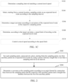
- the computing device 102 may determine a sampling interval matching a current travel speed; select, starting from a current location, sampling points on an expected travel route according to the sampling interval; determine a target curvature according to curvatures of the expected travel route at the respective sampling points; determine, according to the target curvature, a speed limit of traveling on the expected travel route; and control a travel speed of the vehicle 101 according to the speed limit, thereby ensuring safe driving of the vehicle 101.
- FIG. 1C is a schematic flowchart of a travelspeed control method in some embodiments of the invention.
- applying the travel speed control method to a computer device is mainly used as an example for description.
- the computer device may be a terminal or a server.
- the method specifically includes the following blocks.
- S102 Determine a sampling interval matching a current travel speed.
- the sampling interval matching the current travel speed indicates that the current travel speed affects a size of the sampling interval.
- the sampling interval is positively correlated to the current travel speed. Specifically, if the current travel speed is higher, the sampling interval is larger; and if the current travel speed is lower, the sampling interval is smaller.
- Block S102 includes: obtaining a current travel speed and a preset time length; and determining a sampling interval according to a product of the current travel speed and the preset time length.
- the computer device may directly use the product of the current travel speed and the preset time length as the sampling interval.
- the determining a sampling interval according to a product of the current travel speed and the preset time length includes: determining the product of the current travel speed and the preset time length; obtaining a preset sampling interval; and obtaining a minimum value of the product of the current travel speed and the preset time length and the preset sampling interval as the sampling interval.
- d 0 may be 10 m
- t 0 may be 0.5s.
- V current travel speed
- d 0 10 m
- t 0 0.5s
- V ⁇ t 0 7.5 m
- block S102 includes: determining a preset travel speed range within which the current travel speed falls, and searching for, according to a correspondence between the preset travel speed range and a sampling interval, the sampling interval corresponding to the preset travel speed range within which the current travel speed falls.
- the correspondence between the travel speed range and the sampling interval is preset in the computer device.
- the computer device may determine the travel speed range within which the current travel speed falls, and searching for the sampling interval corresponding to the determined travel speed range according to the correspondence, that is, determining the sampling interval matching the current travel speed.
- a corresponding sampling interval is 10 m
- a corresponding sampling interval is 15 m
- a travel speed falls within a range of 31 to 35 m/s
- a corresponding sampling interval is 30 m.
- the current travel speed is 28 m/s
- a range within which the current travel speed falls is 31 to 35 m/s
- a matched sampling interval is 30 m.
- S104 Select, starting from a current location, sampling points on an expected travel route according to the sampling interval.
- the expected travel route is a route that is predicted to be traveled on.
- the expected travel route may be a route formed by a road ahead of a vehicle in a current traveling direction.
- the computer device may select, starting from a current location, sampling points on an expected travel route according to the sampling interval.
- a preset quantity may be 5.
- S106 Determine a target curvature according to curvatures of the expected travel route at the respective sampling points.
- a curvature of the expected travel route at a sampling point represents a value of a degree by which the expected travel route deviates from a tangent of the sampling point, that is, a value of a bending degree of the expected travel route at the sampling point.
- a larger curvature indicates a larger degree by which the expected travel route deviates from the tangent of the sampling point, that is, a larger bending degree of the expected travel route at the point.
- the target curvature is a curvature finally used to determine a speed limit (that is, a maximum speed) of traveling on the expected travel route.
- the computer device may select a maximum curvature from curvatures at the respective sampling points, and determine the target curvature according to the selected maximum curvature.
- the computer device may directly select the maximum curvature as the target curvature.
- the computer device may alternatively obtain an average value of the selected maximum curvature and curvatures at the auxiliary points, and determine the target curvature according to the average value of the curvatures.
- S108 Determine, according to the target curvature, a speed limit of traveling on the expected travel route.
- the speed limit of traveling on expected travel route is a maximum speed of traveling on the expected travel route.
- block S 108 includes: obtaining a preset lateral force coefficient; obtaining an absolute value of the target curvature; and dividing a product of the lateral force coefficient and the acceleration of gravity by the absolute value of the target curvature and then extracting a square root to obtain the speed limit of traveling on the expected travel route.
- a lateral force coefficient is a used to measure a degree of stability of a traveling object when the traveling object travels on a travel route.
- the lateral force coefficient u may be 0.2.
- the computer device may perform speed planning according to the speed limit, and determine a speed of traveling on the expected travel route.
- the sampling interval matches the current travel speed, and sampling points are selected on the expected travel route according to the sampling interval, so that the sampling point are more likely to reflect requirements of travel speed control at the current travel speed. Determining the target curvature according to the curvatures at the selected sampling point can better reflect a bending status of the expected travel route, so that a corner can be found in advance, and further, a speed limit is determined according to a curvature of the corner, thereby accurately controlling a travel speed and reducing sudden speed changes.
- the method further includes a sampling point curvature determining block, specifically including the following blocks: S202: For each sampling point, consecutively select, starting from the sampling point, two first auxiliary points on the expected travel route by using a preset reference length that is less than the sampling interval as an interval.
- the preset reference length is less than the sampling interval. It may be understood that because two first auxiliary points are consecutively selected starting from the sampling point by using the preset reference length on the expected travel route, and an arc length between the sampling point and the first first auxiliary point, and an arc length between two first auxiliary points are both preset reference lengths.
- the preset reference length may be a vehicle axle length.
- the vehicle axle length is a distance from a center of a front axle of a vehicle to a center of a rear axle of the vehicle.
- S204 Determine a curvature at the sampling point according to an angle formed by connection lines between the sampling point and the respective first auxiliary points and a straight-line distance between the two first auxiliary points.
- An angle may be formed by connection lines between the sampling point and the respective corresponding first auxiliary points.
- the straight-line distance between the two first auxiliary points is a length of a line segment between the two first auxiliary points.
- the vehicle axle length may be directly substituted as L into the formula above for calculation.
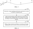
- FIG. 3 is a schematic diagram of curvature calculation in an embodiment.
- P1, P2, P3, and P4 are sampling points
- a point A and a point B are first auxiliary points corresponding to P1 on an expected travel route w.
- the preset reference length between the first auxiliary point and the sampling point P1 is less than the sampling interval between the two sampling points
- ⁇ is an angle formed by connection lines between the sampling point P1 and the corresponding first auxiliary points, namely, the point A and the point B.
- two first auxiliary points on the expected travel route are consecutively selected, starting from the sampling point, by using a preset reference length that is less than the sampling interval as an interval.
- a curvature at the sampling point is determined according to an angle formed by connection lines between the sampling point and the respective first auxiliary points and a straight-line distance between the two first auxiliary points.
- curvature calculation by making two first auxiliary points, a relatively complex calculus curvature calculation method is converted into direct calculation between an angle and a distance, which simplifies processing blocks and improves efficiency of obtaining curvatures at sampling points, thereby improving efficiency of travel speed control.
- block S106 (the target curvature obtaining block for short) specifically includes the following blocks.
- S402 Determine a target sampling point having a maximum curvature in the respective sampling points.
- the target sampling point is a sampling point having a maximum curvature in the respective sampling points.
- the computer device may determine curvatures at respective sampling points, and selects a sampling point having a maximum curvature from the respective sampling points as the target sampling point.
- S404 Select second auxiliary points respectively in front of and behind the target sampling point on the expected travel route according to a preset interval that is shorter than the sampling interval.
- the preset interval is less than the sampling interval. It may be understood that an arc length between the second auxiliary point in front of the target sampling point and the target sampling point and an arc length between the second auxiliary point behind the target sampling point and the target sampling point are both equal to the preset interval.
- the second auxiliary point in front of the target sampling point is a point selected, starting from the target sampling point, on the expected travel route according to the preset interval in a direction opposite to a traveling direction.
- the second auxiliary point behind the target sampling point is a point selected, starting from the target sampling point, on the expected travel route according to the preset interval in the traveling direction.
- At least one second auxiliary point in front of or behind the target sampling point is selected.
- a same quantity of second auxiliary points may be selected in front of or behind the target sampling point. It may be understood that when a plurality of second auxiliary points is selected in front of or behind the target sampling point, an arc length between every two adjacent second auxiliary points is equal to the preset interval.
- S406 Obtain the target curvature according to a curvature at the target sampling point and curvatures at the second auxiliary points.
- the computer device may alternatively obtain an average value of a curvature at the target sampling point and curvatures at the second auxiliary points, and determine the target curvature according to the obtain average value of the curvatures.
- the computer device may obtain a sum of the curvature at the target sampling point and curvatures at the second auxiliary points, and divide the sum by a quantity of the summed curvatures, to obtain an average value of the curvature at the target sampling point and the curvatures at the second auxiliary points.
- the computer device may directly use the obtained average value of the curvature at the target sampling point and the curvatures at the second auxiliary points as the target curvature. In another embodiment, the computer device may alternatively use the obtained average value of the curvature at the target sampling point and the curvatures at the second auxiliary points as the target curvature as a current reference curvature and obtain the target curvature with reference to a historical reference curvature.
- a sampling point having a maximum curvature is first determined, and second auxiliary points are selected at a preset interval in front of or behind the sampling point having the maximum curvature, and a target curvature is determined according to a curvature at a target sampling point and curvatures at the second auxiliary points.
- a target curvature obtained with reference to the curvatures at the two auxiliary points in front and behind is more stable, and compared with a limitation of a curvature at a single sampling point, can reflect a bending status of a travel route more accurately, so that a corner can be found in advance, an further, accurate travel speed control is achieved by determining a speed limit based on a curvature of the corner, thereby reducing sudden speed changes and interference caused by speed planning.
- block S406 includes: generating a current reference curvature according to an average value of the curvature at the target sampling point and the curvatures at the second auxiliary points; obtaining a historical reference curvature; and using an average value of the current reference curvature and the obtained historical reference curvature as the target curvature.
- the historical reference curvature is a reference curvature generated before the current reference curvature. It may be understood that a reference curvature is generated each time a speed limit is calculated, and the historical reference curvature is a reference curvature generated during speed limit calculation before the current speed limit calculation.
- the computer device may directly use the obtained average value of the curvature at the target sampling point and the curvatures at the second auxiliary points as the current reference curvature.
- the computer device may obtain all or some historical reference curvatures.
- the computer device may obtain an average value of the current reference curvature and the obtained historical reference curvature, and use the average value as the target curvature.
- a target curvature is determined with reference to the current reference curvature and the historical reference curvature or by obtaining an average value of the current reference curvature and the historical reference curvature, so that the determined target curvature is more stable, which, compared with a limitation of being monotonously based on the current reference curve, can reflect a bending status of a travel route more accurately.
- the obtaining a historical reference curvature (the historical reference curvature obtaining block for short) specifically includes the following blocks.
- S502 Obtain a speed limit calculation frequency and a preset selection time length.
- the speed limit calculation frequency is a frequency at which a speed limit is calculated. In an embodiment, the speed limit calculation frequency may consistent with a speed planning frequency.
- the speed planning frequency is a frequency at which a speed is planned. In an embodiment, the speed limit calculation frequency may be 10 Hz. That is, a speed limit is calculated 10 times per 1s.
- the preset selection time length is used to determine a selection range of the historical reference curvature.
- the computer device may select a historical reference curvature generated within a preset selection time length before a generation time of the current reference curvature. For example, if the preset selection time length is 1s, the computer device may select a historical reference curvature generated within 1s before a generation time of the current reference curvature.
- S504 Obtain a target quantity according to a product of the speed limit calculation frequency and the preset selection time length.
- the target quantity is a quantity of historical reference curvatures to be selected.
- the computer device may directly use a product of the speed limit calculation frequency and the preset selection time length as a target quantity.
- the target quantity is also a quantity of historical reference curvatures generated within a preset selection time length before the generation time of the current reference curvature.
- a speed limit calculation frequency is 10 Hz
- a preset selection time length is 1s
- the computer device may be select the first target quantity of generated historical reference curvatures before a current reference curvature is generated currently from the historical reference curvatures generated before the current reference curvature is generated. For example, if the target quantity is 10, the computer device may select the first one, the first two, ... until the first ten generated historical reference curvatures before a current reference curvature is generated currently.
- a target quantity is obtained according to a product of the speed limit calculation frequency and the preset selection time length; and the target quantity of historical reference curvatures that are recently generated are obtained before the current reference curvature is generated. Then, the target curvature is determined according to an average value of the historical reference curvature and the current reference curvature. That is, an average value of the reference curvatures is calculated in a time dimension by using the speed limit calculation frequency, so that the final target curvature is an average value result in the time dimension, thereby further improving stability of the target curvature in the time dimension. Therefore, a speed limit determined according to a target curvature is more accurate, thereby preventing a sudden speed change.
- block S406 (the target curvature generating block for short) specifically includes the following blocks.
- S602 Obtain a current reference curvature according to an average value of the curvature at the target sampling point and the curvatures at the second auxiliary points.
- the computer device may directly use the obtained average value of the curvature at the target sampling point and the curvatures at the second auxiliary points as the current reference curvature.
- the computer device may obtain a sum of the curvature at the target sampling point and the curvatures at the second auxiliary points, and divide the sum by a quantity of the summed curvatures, to obtain current reference curvature.
- the previously generated target curvature is a target curvature that is generated previous to current generation, that is, the target curvature generated during speed limit calculation previous to current calculation.
- S606 Average the current reference curvature and the previously generated target curvature in a weighted manner according to a corresponding weight to generate a current target curvature.
- a 1/H/T
- H is a speed limit calculation frequency
- T is a preset selection time length. It may be understood that as the number of iterations increases, a historical target curvature whose generation time is further from a current generation time has a smaller impact on generation of a current target curvature, and finally, a historical target curvature generated within approximately a preset selection time length T before the current generation can have a substantial impact on generation of the current target curvature.
- 1/H is a time length corresponding to generation of a current target curvature
- 1/H/T can reflect a proportion of a time length corresponding to the current generated target curvature to an approximately total time length of the historical target curvature having an impact on generation of the current target curvature, thereby determining a weight of a current reference curvature.
- H 10 Hz
- T 1s.
- a previously generated target curvature serving as input, in combination with the current reference curvature is averaged in a weighted manner according to a corresponding weight to generate a current target curvature. That is, with reference to average value calculation on the target curvature in a time dimension, a final target curvature is an average value result in the time dimension, thereby further improving stability of the target curvature in the time dimensional. Therefore, a speed limit determined according to a target curvature is more accurate, thereby preventing a sudden speed change.
- another travel speed control method is provided, specifically including the following blocks:
- the sampling interval matches the current travel speed, and sampling points are selected on the expected travel route according to the sampling interval, so that the sampling point are more likely to reflect requirements of travel speed control at the current travel speed. Determining the target curvature according to the curvatures at the selected sampling point can better reflect a bending status of the expected travel route, so that a corner can be found in advance, and further, a speed limit is determined according to a curvature of the corner, thereby accurately controlling a travel speed and reducing sudden speed changes.
- a target curvature obtained with reference to the curvatures at the two auxiliary points in front and behind is more stable, and compared with a limitation of a curvature at a single sampling point, can reflect a bending status of a travel route more accurately, so that a corner can be found in advance, an further, accurate travel speed control is achieved by determining a speed limit based on a curvature of the corner, thereby reducing sudden speed changes.
- a target curvature is determined with reference to the current reference curvature and the historical reference curvature or by obtaining an average value of the current reference curvature and the historical reference curvature, so that the determined target curvature is more stable, which, compared with a limitation of being monotonously based on the current reference curve, can reflect a bending status of a travel route more accurately.
- an average value of the reference curvatures is calculated in a time dimension by using the speed limit calculation frequency, so that the finally obtained target curvature is an average value result in the time dimension, thereby further improving stability of the target curvature in the time dimension. Therefore, a speed limit determined according to a target curvature is more accurate, thereby preventing a sudden speed change.
- a travel speed control apparatus 800 includes: a sampling interval determining module 802, a sampling point selection module 804, a target curvature determining module 808, a speed limit determining module 810, and a travel speed control module 812.
- the sampling interval determining module 802 is configured to determine a sampling interval matching a current travel speed.
- the sampling point selection module 804 is configured to select, starting from a current location, sampling points on an expected travel route according to the sampling interval.
- the target curvature determining module 808 is configured to determine a target curvature according to curvatures of the expected travel route at the respective sampling points.
- the speed limit determining module 810 is configured to determine, according to the target curvature, a speed limit of traveling on the expected travel route.
- the travel speed control module 812 is configured to control a travel speed according to the speed limit.
- the sampling interval determining module 802 is further configured to obtain a current travel speed and a preset time length; and determine a sampling interval according to a product of the current travel speed and the preset time length.
- the sampling interval determining module 802 is further configured to determine the product of the current travel speed and the preset time length; obtain a preset sampling interval; and obtain a minimum value of the product of the current travel speed and the preset time length and the preset sampling interval as the sampling interval.
- a travel speed control apparatus 900 includes: a sampling interval determining module 902, a sampling point selection module 904, a target curvature determining module 908, a speed limit determining module 910, and a travel speed control module 912.
- the sampling interval determining module 902 is configured to determine a sampling interval matching a current travel speed.
- the sampling point selection module 904 is configured to select, starting from a current location, sampling points on an expected travel route according to the sampling interval.
- the target curvature determining module 908 is configured to determine a target curvature according to curvatures of the expected travel route at the respective sampling points.
- the speed limit determining module 910 is configured to determine, according to the target curvature, a speed limit of traveling on the expected travel route.
- the travel speed control module 912 is configured to control a travel speed according to the speed limit.
- the sampling interval determining module 902 is further configured to obtain a current travel speed and a preset time length; and determine a sampling interval according to a product of the current travel speed and the preset time length.
- the sampling interval determining module 902 is further configured to determine the product of the current travel speed and the preset time length; obtain a preset sampling interval; obtain a minimum value of the product of the current travel speed and the preset time length and the preset sampling interval as the sampling interval.
- the apparatus 900 further includes:
- the target curvature determining module 908 is further configured to determine a target sampling point having a maximum curvature in the respective sampling points; select second auxiliary points respectively in front of and behind the target sampling point on the expected travel route according to a preset interval shorter than the sampling interval; and obtain the target curvature according to a curvature at the target sampling point and curvatures at the second auxiliary points.
- the target curvature determining module 908 is further configured to generate a current reference curvature according to an average value of the curvature at the target sampling point and the curvatures at the second auxiliary points; obtain a historical reference curvature; and use an average value of the current reference curvature and the obtained historical reference curvature as the target curvature.
- the target curvature determining module 908 is further configured to obtain a speed limit calculation frequency and a preset selection time length; obtain a target quantity according to a product of the speed limit calculation frequency and the preset selection time length; and obtain the target quantity of historical reference curvatures that are recently generated before the current reference curvature is generated.
- the target curvature determining module 908 is further configured to obtain a current reference curvature according to an average value of the curvature at the target sampling point and the curvatures at the second auxiliary points; obtain a previously generated target curvature; and average the current reference curvature and the previously generated target curvature in a weighted manner according to a corresponding weight to generate a current target curvature.
- the speed limit determining module 910 is further configured to: obtain a preset lateral force coefficient; obtain an absolute value of the target curvature; and divide a product of the lateral force coefficient and the acceleration of gravity by the absolute value and then extracting a square root to obtain the speed limit of traveling on the expected travel route.
- FIG. 10 is a schematic diagram of an inner structure of a computer device in an embodiment.
- the computer device may be a terminal or a server.
- the terminal may be a personal computer or a mobile electronic device, including at least one of a mobile phone, a tablet computer, a personal digital assistant, wearable device, or the like.
- the server may be an independent server or implemented by using a server cluster including multiple physical servers.
- the electronic device 1000 includes a processor 1002, a non-volatile storage medium 1004, an internal memory 1006, and a network interface 1008 that are connected through a system bus.
- the non-volatile storage medium 1004 of the computer device may store an operating system 1010 and a computer program 1012.
- the computer program 1012 when executed, may cause the processor to perform a travel speed control method.
- the processor 1002 of the computer device is configured to provide calculation and control capabilities, to support running of the entire computer device.
- the internal memory 1006 may store the computer program 1012.
- the computer program 1012 When executed by the processor 1002, the computer program 1012 may cause the processor 1002 to perform a travel speed control method.
- the network interface 1008 of the computer device is configured to perform network communication.
- FIG. 10 is merely a block diagram of a partial structure related to the solutions of the invention, and does not constitute a limitation to the computer device to which the solutions of the invention are applied, and a specific computer device may include more or fewer components than those shown in the figure, or some components may be combined, or a different component deployment may be used.
- the travel speed control apparatus may be implemented in a form of a computer program.
- the computer program may run on the computer device 1000 shown FIG. 10 , and the non-volatile storage medium of the computer device may store respective program modules constituting the travel speed control apparatus, for example, the sampling interval determining module 802, the sampling point selection module 804, the target curvature determining module 808, the speed limit determining module 810, and the travel speed control module 812, as shown in FIG. 8 .
- the program modules include a computer program.
- the computer program is may be executed by one or more processors to cause the computer device to perform functions of the corresponding module and blocks in the travel speed control method of each embodiment of the invention described in this specification.
- the computer device may determine, by using the sampling interval determining module 802 in the travel speed control apparatus 800 shown in FIG. 8 , a sampling interval matching a current travel speed; select, starting from a current location, sampling points on an expected travel route according to the sampling interval by using the sampling point selection module 804; determine a target curvature according to curvatures at the respective sampling points by using the target curvature determining module 808; determine, according to the target curvature, a speed limit of traveling on the expected travel route by using the speed limit determining module 810; and control a travel speed according to the speed limit by using the travel speed control module 812.
- a computer device including: a memory and a processor, the memory storing a computer program, and the computer program, when executed by the processor, causing the processor to perform the following blocks:
- the determining a sampling interval matching a current travel speed includes:
- the determining a sampling interval according to a product of the current travel speed and the preset time length includes:
- the computer program before the determining a target curvature according to curvatures at the respective sampling points, the computer program further causes the processor to perform the following blocks:
- the determining a target curvature according to curvatures at the respective sampling points includes:
- the obtaining a historical reference curvature includes:
- the obtaining the target curvature according to a curvature at the target sampling point and curvatures at the second auxiliary points includes:
- the averaging the current reference curvature and the previously generated target curvature in a weighted manner according to a corresponding weight to generate a current target curvature includes:
- the determining, according to the target curvature, a speed limit of traveling on the expected travel route includes:
- a storage medium storing a computer program is further provided, the computer program, when executed by one or more processors, causing the one or more processors to perform the following blocks:
- the determining a sampling interval matching a current travel speed includes:
- the determining a sampling interval according to a product of the current travel speed and the preset time length includes:
- the computer program before the determining a target curvature according to curvatures at the respective sampling points, the computer program further causes the processor to perform the following blocks:
- the determining a target curvature according to curvatures at the respective sampling points includes:
- the obtaining the target curvature according to a curvature at the target sampling point and curvatures at the second auxiliary points includes:
- the obtaining a historical reference curvature includes:
- the obtaining the target curvature according to a curvature at the target sampling point and curvatures at the second auxiliary points includes:
- the averaging the current reference curvature and the previously generated target curvature in a weighted manner according to a corresponding weight to generate a current target curvature includes:
- the determining, according to the target curvature, a speed limit of traveling on the expected travel route includes:
- the program may be stored in a computer readable storage medium.
- the storage medium may be a non-volatile storage medium such as a magnetic disk, an optical disc, or a read-only memory (ROM), or may be a random access memory (RAM) or the like.
Landscapes
- Engineering & Computer Science (AREA)
- Transportation (AREA)
- Mechanical Engineering (AREA)
- Automation & Control Theory (AREA)
- Physics & Mathematics (AREA)
- Mathematical Physics (AREA)
- Chemical & Material Sciences (AREA)
- Combustion & Propulsion (AREA)
- Human Computer Interaction (AREA)
- Control Of Driving Devices And Active Controlling Of Vehicle (AREA)
- Traffic Control Systems (AREA)
- Control Of Position, Course, Altitude, Or Attitude Of Moving Bodies (AREA)
Claims (14)
- Fahrgeschwindigkeitssteuerungsverfahren, angewandt auf eine Computervorrichtung, umfassend:Bestimmen (102) eines Abtastintervalls, das einer gegenwärtigen Fahrgeschwindigkeit entspricht;Auswählen (104), beginnend von einem gegenwärtigen Ort, von Abtastpunkten auf der erwarteten Fahrtroute gemäß dem Abtastintervall;Bestimmen (106) einer Zielkrümmung gemäß den Krümmungen der erwarteten Fahrtroute an den jeweiligen Abtastpunkten;Bestimmen (108), gemäß der Zielkrümmung, einer Geschwindigkeitsbegrenzung von Fahren auf der erwarteten Fahrtroute; undSteuern (110) einer Fahrgeschwindigkeit gemäß der Geschwindigkeitsbegrenzung;wobei das Bestimmen (102) des Abtastintervalls, das der gegenwärtigen Fahrgeschwindigkeit entspricht, umfasst:Erlangen der gegenwärtigen Fahrgeschwindigkeit und einer im Voraus eingestellten Zeitdauer; undBestimmen des Abtastintervalls gemäß einem Produkt der gegenwärtigen Fahrgeschwindigkeit und der im Voraus eingestellten Zeitdauer.
- Verfahren nach Anspruch 1, wobei das Bestimmen des Abtastintervalls gemäß dem Produkt der gegenwärtigen Fahrgeschwindigkeit und der im Voraus eingestellten Zeitdauer umfasst:Bestimmen des Produkts der gegenwärtigen Fahrgeschwindigkeit und der im Voraus eingestellten Zeitdauer;Erlangen eines im Voraus eingestellten Abtastintervalls; undErlangen eines minimalen Werts des Produkts der gegenwärtigen Fahrgeschwindigkeit und der im Voraus eingestellten Zeitdauer und des im Voraus eingestellten Abtastintervalls als das Abtastintervall.
- Verfahren nach Anspruch 1, wobei das Verfahren vor dem Bestimmen der Zielkrümmung gemäß Krümmungen der erwarteten Fahrtroute an den jeweiligen Abtastpunkten ferner umfasst:für jeden Abtastpunkt,aufeinanderfolgendes Auswählen (202), beginnend von dem Abtastpunkt, von zwei ersten Hilfspunkten auf der erwarteten Fahrtroute durch Verwendung einer im Voraus eingestellten Referenzlänge, die kürzer als das Abtastintervall ist, als ein Intervall; undBestimmen (204) einer Krümmung an dem Abtastpunkt gemäß einem Winkel, der durch Verbindungslinien zwischen dem Abtastpunkt und den jeweiligen ersten Hilfspunkten gebildet wird, und einer geradlinigen Distanz zwischen den zwei ersten Hilfspunkten.
- Verfahren nach Anspruch 1, wobei das Bestimmen der Zielkrümmung gemäß Krümmungen der erwarteten Fahrtroute an den jeweiligen Abtastpunkten umfasst:Bestimmen (402) eines Zielabtastpunkts mit einer maximalen Krümmung in den jeweiligen Abtastpunkten;Auswählen (404) von zweiten Hilfspunkten jeweils vor und hinter dem Zielabtastpunkt auf der erwarteten Fahrtroute gemäß einem im Voraus eingestellten Intervall, das kürzer als das Abtastintervall ist; undErlangen (406) der Zielkrümmung gemäß einer Krümmung an dem Zielabtastpunkt und Krümmungen an den zweiten Hilfspunkten.
- Verfahren nach Anspruch 4, wobei das Erlangen der Zielkrümmung gemäß der Krümmung an dem Zielabtastpunkt und Krümmungen an den zweiten Hilfspunkten umfasst:Erzeugen einer gegenwärtigen Referenzkrümmung gemäß einem Durchschnittswert der Krümmung an dem Zielabtastpunkt und der Krümmungen an den zweiten Hilfspunkten;Erlangen von historischen Referenzkrümmungen; undVerwenden eines Durchschnittswerts der gegenwärtigen Referenzkrümmung und der erlangten historischen Referenzkrümmungen als die Zielkrümmung.
- Verfahren nach Anspruch 5, wobei das Erlangen der historischen Referenzkrümmungen umfasst:Erlangen (502) einer Geschwindigkeitsbegrenzung-Berechnungshäufigkeit und einer im Voraus eingestellten Auswahlzeitlänge;Erlangen (504) einer Zielquantität gemäß einem Produkt der Geschwindigkeitsbegrenzung-Berechnungshäufigkeit und der im Voraus eingestellten Auswahlzeitlänge; undErlangen (506) der Zielquantität von historischen Referenzkrümmungen, die kürzlich erzeugt werden, bevor die gegenwärtige Referenzkrümmung erzeugt wird.
- Verfahren nach Anspruch 4, wobei das Erlangen der Zielkrümmung gemäß der Krümmung an dem Zielabtastpunkt und Krümmungen an den zweiten Hilfspunkten umfasst:Erlangen (602) einer gegenwärtigen Referenzkrümmung gemäß einem Durchschnittswert der Krümmung an dem Zielabtastpunkt und der Krümmungen an den zweiten Hilfspunkten;Erlangen (604) einer vorher erzeugten Zielkrümmung; undMitteln (606) der gegenwärtigen Referenzkrümmung und der vorher erzeugten Zielkrümmung in einer gewichteten Weise gemäß einem korrespondierenden Gewicht zum Erzeugen einer gegenwärtigen Zielkrümmung.
- Verfahren nach Anspruch 7, wobei das Mitteln der gegenwärtigen Referenzkrümmung und der vorher erzeugten Zielkrümmung in der gewichteten Weise gemäß dem korrespondierenden Gewicht zum Erzeugen der gegenwärtigen Zielkrümmung umfasst:Erzeugen der gegenwärtigen Zielkrümmung gemäß der folgenden Formel:
 KA_now die gegenwärtige Zielkrümmung repräsentiert, KA_pre die vorher erzeugte Zielkrümmung repräsentiert, KR_now die gegenwärtige Referenzkrümmung repräsentiert und a ein Gewicht der gegenwärtigen Referenzkrümmung ist.
 - Verfahren nach einem der Ansprüche 1 bis 8, wobei das Bestimmen, gemäß der Zielkrümmung, der Geschwindigkeitsbegrenzung von Fahren auf der erwarteten Fahrtroute umfasst:Erlangen eines im Voraus eingestellten Seitenkraftkoeffizienten;Erlangen eines Absolutwerts der Zielkrümmung; undDividieren eines Produkts des Seitenkraftkoeffizienten und der Schwerebeschleunigung durch den Absolutwert der Zielkrümmung und dann Extrahieren einer Quadratwurzel, um die Geschwindigkeitsbegrenzung von Fahren auf der erwarteten Fahrtroute zu erlangen.
- Fahrgeschwindigkeitssteuerungsgerät, umfassend:ein Abtastintervall-Bestimmungsmodul (802), konfiguriert zum Bestimmen eines Abtastintervalls, das einer gegenwärtigen Fahrgeschwindigkeit entspricht;ein Abtastpunkt-Auswahlmodul (804), konfiguriert zum Auswählen, beginnend von einem gegenwärtigen Ort, von Abtastpunkten auf der erwarteten Fahrtroute gemäß dem Abtastintervall;ein Zielkrümmung-Bestimmungsmodul (808), konfiguriert zum Bestimmen einer Zielkrümmung gemäß den Krümmungen der erwarteten Fahrtroute an den jeweiligen Abtastpunkten;ein Geschwindigkeitsbegrenzung-Bestimmungsmodul (810), konfiguriert zum Bestimmen, gemäß der Zielkrümmung, einer Geschwindigkeitsbegrenzung von Fahren auf der erwarteten Fahrtroute; undein Fahrgeschwindigkeitssteuerungsmodul (812), konfiguriert zum Steuern einer Fahrgeschwindigkeit gemäß der Geschwindigkeitsbegrenzung;wobei das Abtastintervall-Bestimmungsmodul (802) ferner konfiguriert ist zum Erlangen der gegenwärtigen Fahrgeschwindigkeit und einer im Voraus eingestellten Zeitdauer; und Bestimmen des Abtastintervalls gemäß einem Produkt der gegenwärtigen Fahrgeschwindigkeit und der im Voraus eingestellten Zeitdauer.
- Gerät nach Anspruch 10, ferner umfassend:ein Hilfspunkt-Auswahlmodul (905), konfiguriert zum aufeinanderfolgendes Auswählen, für jeden Abtastpunkt, beginnend von dem Abtastpunkt, von zwei ersten Hilfspunkten auf der erwarteten Fahrtroute durch Verwendung einer im Voraus eingestellten Referenzlänge, die kürzer als das Abtastintervall ist, als ein Intervall; undein Abtastpunktkrümmung-Bestimmungsmodul (906), konfiguriert zum Bestimmen einer Krümmung an dem Abtastpunkt gemäß einem Winkel, der durch Verbindungslinien zwischen dem Abtastpunkt und den jeweiligen ersten Hilfspunkten gebildet wird, und einer geradlinigen Distanz zwischen den zwei ersten Hilfspunkten.
- Gerät nach Anspruch 10 oder 11, wobei das Zielkrümmung-Bestimmungsmodul (808) ferner konfiguriert ist zum Bestimmen eines Zielabtastpunkts mit einer maximalen Krümmung in den jeweiligen Abtastpunkten; Auswählen von zweiten Hilfspunkten jeweils vor und hinter dem Zielabtastpunkt auf der erwarteten Fahrtroute gemäß einem im Voraus eingestellten Intervall, das kürzer als das Abtastintervall ist; und Erlangen der Zielkrümmung gemäß einer Krümmung an dem Zielabtastpunkt und Krümmungen an den zweiten Hilfspunkten.
- Computervorrichtung, umfassend: einen Speicher und einen Prozessor, wobei der Speicher ein Computerprogramm speichert und das Computerprogramm, wenn es durch den Prozessor ausgeführt wird, den Prozessor veranlasst, die Operationen des Verfahrens nach einem der Ansprüche 1 bis 9 durchzuführen.
- Speichermedium, das ein Computerprogramm speichert, wobei das Computerprogramm, wenn es durch einen oder mehrere Prozessoren ausgeführt wird, den einen oder die mehreren Prozessoren veranlasst, die Operationen des Verfahrens nach einem der Ansprüche 1 bis 9 durchzuführen.
Applications Claiming Priority (2)
| Application Number | Priority Date | Filing Date | Title |
|---|---|---|---|
| CN201710725387.0A CN108297876B (zh) | 2017-08-22 | 2017-08-22 | 行驶速度控制方法、装置、计算机设备和存储介质 |
| PCT/CN2018/101038 WO2019037662A1 (zh) | 2017-08-22 | 2018-08-17 | 行驶速度控制方法、装置、计算机设备和存储介质 |
Publications (3)
| Publication Number | Publication Date |
|---|---|
| EP3604069A1 EP3604069A1 (de) | 2020-02-05 |
| EP3604069A4 EP3604069A4 (de) | 2020-10-28 |
| EP3604069B1 true EP3604069B1 (de) | 2023-06-07 |
Family
ID=62869242
Family Applications (1)
| Application Number | Title | Priority Date | Filing Date |
|---|---|---|---|
| EP18847584.2A Active EP3604069B1 (de) | 2017-08-22 | 2018-08-17 | Fahrgeschwindigkeitssteuerungsverfahren, vorrichtung, computervorrichtung und speichermedium |
Country Status (6)
| Country | Link |
|---|---|
| US (1) | US11318942B2 (de) |
| EP (1) | EP3604069B1 (de) |
| JP (1) | JP6906690B2 (de) |
| KR (1) | KR102282753B1 (de) |
| CN (1) | CN108297876B (de) |
| WO (1) | WO2019037662A1 (de) |
Families Citing this family (21)
| Publication number | Priority date | Publication date | Assignee | Title |
|---|---|---|---|---|
| CN108297876B (zh) * | 2017-08-22 | 2019-09-17 | 腾讯科技(深圳)有限公司 | 行驶速度控制方法、装置、计算机设备和存储介质 |
| CN109215369B (zh) * | 2018-09-20 | 2021-07-06 | 北京新能源汽车股份有限公司 | 一种adas系统的控制方法、装置、设备及网络设备 |
| US11199847B2 (en) | 2018-09-26 | 2021-12-14 | Baidu Usa Llc | Curvature corrected path sampling system for autonomous driving vehicles |
| CN109976337A (zh) * | 2019-03-11 | 2019-07-05 | 智久(厦门)机器人科技有限公司上海分公司 | 一种自动导引装置的弯道速度规划方法、装置 |
| CN111688683B (zh) * | 2019-03-13 | 2021-05-25 | 长沙智能驾驶研究院有限公司 | 车辆行驶状态控制方法、装置、计算机设备和存储介质 |
| CN115973194A (zh) * | 2019-11-19 | 2023-04-18 | 深圳市镭神智能系统有限公司 | 智能车辆控制方法、装置、设备及介质 |
| CN113763739B (zh) * | 2020-06-04 | 2022-08-05 | 比亚迪股份有限公司 | 一种车辆行驶路径确定方法、装置、设备及介质 |
| CN111845743B (zh) * | 2020-07-14 | 2021-10-19 | 肇庆小鹏汽车有限公司 | 车辆巡航控制方法、装置、车辆以及存储介质 |
| CN111862604B (zh) * | 2020-07-20 | 2022-03-04 | 北京京东乾石科技有限公司 | 无人车的控制方法及装置、计算机存储介质、电子设备 |
| CN114248840B (zh) * | 2020-09-24 | 2026-02-13 | 株式会社斯巴鲁 | 车辆的控制装置 |
| JP7697813B2 (ja) * | 2020-09-24 | 2025-06-24 | 株式会社Subaru | 車両の制御装置 |
| CN114312746B (zh) * | 2020-09-29 | 2024-08-06 | 奥迪股份公司 | 辅助驾驶装置以及相应的车辆、方法、计算机设备和介质 |
| CN113753042B (zh) * | 2020-10-30 | 2023-06-30 | 北京京东乾石科技有限公司 | 无人车限速方法、装置、无人车及存储介质 |
| CN112721930A (zh) * | 2021-01-15 | 2021-04-30 | 重庆长安汽车股份有限公司 | 车辆过弯减速度规划方法、系统、车辆及存储介质 |
| CN113409591B (zh) * | 2021-06-23 | 2023-02-03 | 广州小鹏自动驾驶科技有限公司 | 弯道限速方法、车载终端、车辆以及计算机可读存储介质 |
| CN113581204B (zh) * | 2021-08-02 | 2023-06-16 | 深圳一清创新科技有限公司 | 一种无人驾驶地图中路径限速值估计方法、电子设备及存储介质 |
| CN113752854B (zh) * | 2021-09-17 | 2023-01-31 | 江苏英拓动力科技有限公司 | 基于单侧电机驱动的无人履带车指定目标位置的行驶控制系统和方法 |
| CN114501306B (zh) * | 2021-12-29 | 2024-05-14 | 中国电信股份有限公司 | 一种采样方法、装置、电子设备及存储介质 |
| JP2024131971A (ja) * | 2023-03-17 | 2024-09-30 | 株式会社アイシン | 車両制御装置 |
| CN118144783A (zh) * | 2024-02-06 | 2024-06-07 | 岚图汽车科技有限公司 | 弯道巡航的车辆控制方法、装置、设备及存储介质 |
| CN118584964B (zh) * | 2024-08-01 | 2024-11-26 | 中汽智联技术有限公司 | 无人驾驶目标速度规划方法、电子设备及介质 |
Family Cites Families (21)
| Publication number | Priority date | Publication date | Assignee | Title |
|---|---|---|---|---|
| JP3432881B2 (ja) * | 1994-02-23 | 2003-08-04 | 本田技研工業株式会社 | 車両制御装置 |
| JP3385812B2 (ja) * | 1995-08-09 | 2003-03-10 | 三菱自動車工業株式会社 | 自動車の前方道路状況対応制御装置 |
| JP4438644B2 (ja) * | 2005-03-04 | 2010-03-24 | トヨタ自動車株式会社 | 車輌走行制御装置 |
| US7774121B2 (en) * | 2007-07-31 | 2010-08-10 | Gm Global Technology Operations, Inc. | Curve speed control system with adaptive map preview time and driving mode selection |
| US8700256B2 (en) * | 2008-08-22 | 2014-04-15 | Daimler Trucks North America Llc | Vehicle disturbance estimator and method |
| JP4766152B2 (ja) * | 2009-05-13 | 2011-09-07 | トヨタ自動車株式会社 | 車両走行制御装置 |
| WO2011024220A1 (ja) | 2009-08-26 | 2011-03-03 | 三菱電機株式会社 | 駐車支援装置 |
| JP5414454B2 (ja) * | 2009-10-23 | 2014-02-12 | 日立オートモティブシステムズ株式会社 | 車両運動制御装置 |
| CN102001338A (zh) * | 2010-10-28 | 2011-04-06 | 奇瑞汽车股份有限公司 | 车辆安全行驶的控制方法和装置 |
| CN103376118B (zh) * | 2012-04-27 | 2017-02-15 | 北京四维图新科技股份有限公司 | 基于曲率的辅助驾驶的方法及装置 |
| KR101338592B1 (ko) * | 2012-06-12 | 2013-12-06 | 기아자동차주식회사 | 스마트 크루즈 컨트롤 시스템의 곡선로 속도 제어 장치 및 방법 |
| KR102037036B1 (ko) * | 2013-04-11 | 2019-10-28 | 현대모비스 주식회사 | 자동주행 제어시스템 |
| JP6161942B2 (ja) * | 2013-04-19 | 2017-07-12 | 株式会社デンソーアイティーラボラトリ | カーブ形状モデル化装置、車両情報処理システム、カーブ形状モデル化方法、及びカーブ形状モデル化プログラム |
| KR101504252B1 (ko) * | 2013-11-28 | 2015-03-19 | 현대모비스 주식회사 | 곡선 도로에서 차량의 속도를 제어하기 위한 시스템 및 그 방법 |
| KR20150062490A (ko) | 2013-11-29 | 2015-06-08 | 주식회사 만도 | 차량의 차속 제어 장치 및 방법 |
| SE539778C2 (sv) * | 2014-05-21 | 2017-11-28 | Scania Cv Ab | Förfarande och system för anpassning av ett fordons framförande på en vägbana i samband med kurvkörning |
| DE102015116877B4 (de) * | 2014-10-06 | 2025-03-13 | Hl Klemove Corp. | Geschwindigkeitssteuersystem und geschwindigkeitssteuerverfahren für gekrümmte strassenabschnitte |
| JP6512084B2 (ja) * | 2015-12-04 | 2019-05-15 | 株式会社デンソー | 走行軌跡生成装置、走行軌跡生成方法 |
| CN106114507B (zh) | 2016-06-21 | 2018-04-03 | 百度在线网络技术(北京)有限公司 | 用于智能车辆的局部轨迹规划方法和装置 |
| CN106740868B (zh) * | 2016-12-30 | 2019-03-29 | 东软集团股份有限公司 | 一种车速规划的方法、装置和设备 |
| CN108297876B (zh) * | 2017-08-22 | 2019-09-17 | 腾讯科技(深圳)有限公司 | 行驶速度控制方法、装置、计算机设备和存储介质 |
-
2017
- 2017-08-22 CN CN201710725387.0A patent/CN108297876B/zh active Active
-
2018
- 2018-08-17 JP JP2020510587A patent/JP6906690B2/ja active Active
- 2018-08-17 KR KR1020197031001A patent/KR102282753B1/ko active Active
- 2018-08-17 EP EP18847584.2A patent/EP3604069B1/de active Active
- 2018-08-17 WO PCT/CN2018/101038 patent/WO2019037662A1/zh not_active Ceased
-
2019
- 2019-08-31 US US16/558,057 patent/US11318942B2/en active Active
Also Published As
| Publication number | Publication date |
|---|---|
| EP3604069A1 (de) | 2020-02-05 |
| CN108297876A (zh) | 2018-07-20 |
| WO2019037662A1 (zh) | 2019-02-28 |
| KR20190127903A (ko) | 2019-11-13 |
| US11318942B2 (en) | 2022-05-03 |
| US20190382014A1 (en) | 2019-12-19 |
| CN108297876B (zh) | 2019-09-17 |
| JP2020531354A (ja) | 2020-11-05 |
| JP6906690B2 (ja) | 2021-07-21 |
| EP3604069A4 (de) | 2020-10-28 |
| KR102282753B1 (ko) | 2021-07-27 |
Similar Documents
| Publication | Publication Date | Title |
|---|---|---|
| EP3604069A1 (de) | Fahrgeschwindigkeitssteuerungsverfahren, vorrichtung, computervorrichtung und speichermedium | |
| CN109658697A (zh) | 交通拥堵的预测方法、装置和计算机设备 | |
| CN111833607A (zh) | 用于在社区云中进行路线导航共享的技术 | |
| JP7669252B2 (ja) | 車両およびその制御方法 | |
| US11598641B2 (en) | Charging facility guidance system and charging facility guidance device | |
| CN110501013B (zh) | 位置补偿方法、装置及电子设备 | |
| CN111076737A (zh) | 基于车辆和推进系统特征的路线确定方法及系统 | |
| CN107091648A (zh) | 一种激光雷达与差分gps的数据融合方法及系统 | |
| CN116587892B (zh) | 车辆增程器控制方法、装置、电子设备及存储介质 | |
| CN114838737B (zh) | 一种行驶路径的确定方法、装置、电子设备及存储介质 | |
| CN107985096A (zh) | 一种电动车物流系统中电动车的充电提示方法及装置 | |
| CN113805578A (zh) | 无人车路径优化方法及相关设备 | |
| CN118254811A (zh) | 车辆驾驶意图预测方法、装置、设备和计算机存储介质 | |
| CN112857382B (zh) | 一种出行路线选择方法及装置 | |
| US10824309B2 (en) | Navigation system with notification mechanism and method of operation thereof | |
| WO2026040604A1 (zh) | 车道推荐方法、存储介质、电子设备及目标车辆 | |
| US20250207922A1 (en) | Navigation method and apparatus, electronic device, storage medium, and program product | |
| CN115016758A (zh) | 数据处理的方法、装置、设备和存储介质 | |
| CN111896020B (zh) | 用于信息处理的方法、电子设备和存储介质 | |
| CN118701110B (zh) | 轨迹预测方法、装置、车载终端、车辆及存储介质 | |
| CN120232412A (zh) | 车道构建方法、装置、设备、存储介质以及产品 | |
| WO2024078334A1 (zh) | 地图数据的处理方法、装置、车辆及可读存储介质 | |
| CN113581205B (zh) | 一种调整车辆姿态的方法和装置 | |
| CN117636659A (zh) | 车辆限速方法、车辆行驶控制方法、电子设备和存储介质 | |
| US11371860B2 (en) | Method and apparatus for adaptive scaling route display |
Legal Events
| Date | Code | Title | Description |
|---|---|---|---|
| STAA | Information on the status of an ep patent application or granted ep patent |
Free format text: STATUS: THE INTERNATIONAL PUBLICATION HAS BEEN MADE |
|
| PUAI | Public reference made under article 153(3) epc to a published international application that has entered the european phase |
Free format text: ORIGINAL CODE: 0009012 |
|
| STAA | Information on the status of an ep patent application or granted ep patent |
Free format text: STATUS: REQUEST FOR EXAMINATION WAS MADE |
|
| 17P | Request for examination filed |
Effective date: 20191021 |
|
| AK | Designated contracting states |
Kind code of ref document: A1 Designated state(s): AL AT BE BG CH CY CZ DE DK EE ES FI FR GB GR HR HU IE IS IT LI LT LU LV MC MK MT NL NO PL PT RO RS SE SI SK SM TR |
|
| AX | Request for extension of the european patent |
Extension state: BA ME |
|
| A4 | Supplementary search report drawn up and despatched |
Effective date: 20200929 |
|
| RIC1 | Information provided on ipc code assigned before grant |
Ipc: B60W 50/00 20060101AFI20200923BHEP Ipc: B60W 30/095 20120101ALI20200923BHEP |
|
| DAV | Request for validation of the european patent (deleted) | ||
| DAX | Request for extension of the european patent (deleted) | ||
| RAP3 | Party data changed (applicant data changed or rights of an application transferred) |
Owner name: TENCENT TECHNOLOGY (SHENZHEN) COMPANY LIMITED |
|
| REG | Reference to a national code |
Ref country code: DE Free format text: PREVIOUS MAIN CLASS: B60W0050000000 Ipc: B60W0030140000 Ref country code: DE Ref legal event code: R079 Ref document number: 602018051522 Country of ref document: DE Free format text: PREVIOUS MAIN CLASS: B60W0050000000 Ipc: B60W0030140000 |
|
| RIC1 | Information provided on ipc code assigned before grant |
Ipc: B60W 30/18 20120101ALI20221213BHEP Ipc: B60W 30/14 20060101AFI20221213BHEP |
|
| GRAP | Despatch of communication of intention to grant a patent |
Free format text: ORIGINAL CODE: EPIDOSNIGR1 |
|
| STAA | Information on the status of an ep patent application or granted ep patent |
Free format text: STATUS: GRANT OF PATENT IS INTENDED |
|
| INTG | Intention to grant announced |
Effective date: 20230127 |
|
| GRAS | Grant fee paid |
Free format text: ORIGINAL CODE: EPIDOSNIGR3 |
|
| GRAA | (expected) grant |
Free format text: ORIGINAL CODE: 0009210 |
|
| STAA | Information on the status of an ep patent application or granted ep patent |
Free format text: STATUS: THE PATENT HAS BEEN GRANTED |
|
| AK | Designated contracting states |
Kind code of ref document: B1 Designated state(s): AL AT BE BG CH CY CZ DE DK EE ES FI FR GB GR HR HU IE IS IT LI LT LU LV MC MK MT NL NO PL PT RO RS SE SI SK SM TR |
|
| REG | Reference to a national code |
Ref country code: GB Ref legal event code: FG4D |
|
| REG | Reference to a national code |
Ref country code: CH Ref legal event code: EP Ref country code: AT Ref legal event code: REF Ref document number: 1574118 Country of ref document: AT Kind code of ref document: T Effective date: 20230615 Ref country code: DE Ref legal event code: R096 Ref document number: 602018051522 Country of ref document: DE |
|
| REG | Reference to a national code |
Ref country code: LT Ref legal event code: MG9D |
|
| REG | Reference to a national code |
Ref country code: NL Ref legal event code: MP Effective date: 20230607 |
|
| PG25 | Lapsed in a contracting state [announced via postgrant information from national office to epo] |
Ref country code: SE Free format text: LAPSE BECAUSE OF FAILURE TO SUBMIT A TRANSLATION OF THE DESCRIPTION OR TO PAY THE FEE WITHIN THE PRESCRIBED TIME-LIMIT Effective date: 20230607 Ref country code: NO Free format text: LAPSE BECAUSE OF FAILURE TO SUBMIT A TRANSLATION OF THE DESCRIPTION OR TO PAY THE FEE WITHIN THE PRESCRIBED TIME-LIMIT Effective date: 20230907 Ref country code: ES Free format text: LAPSE BECAUSE OF FAILURE TO SUBMIT A TRANSLATION OF THE DESCRIPTION OR TO PAY THE FEE WITHIN THE PRESCRIBED TIME-LIMIT Effective date: 20230607 |
|
| REG | Reference to a national code |
Ref country code: AT Ref legal event code: MK05 Ref document number: 1574118 Country of ref document: AT Kind code of ref document: T Effective date: 20230607 |
|
| PG25 | Lapsed in a contracting state [announced via postgrant information from national office to epo] |
Ref country code: RS Free format text: LAPSE BECAUSE OF FAILURE TO SUBMIT A TRANSLATION OF THE DESCRIPTION OR TO PAY THE FEE WITHIN THE PRESCRIBED TIME-LIMIT Effective date: 20230607 Ref country code: NL Free format text: LAPSE BECAUSE OF FAILURE TO SUBMIT A TRANSLATION OF THE DESCRIPTION OR TO PAY THE FEE WITHIN THE PRESCRIBED TIME-LIMIT Effective date: 20230607 Ref country code: LV Free format text: LAPSE BECAUSE OF FAILURE TO SUBMIT A TRANSLATION OF THE DESCRIPTION OR TO PAY THE FEE WITHIN THE PRESCRIBED TIME-LIMIT Effective date: 20230607 Ref country code: LT Free format text: LAPSE BECAUSE OF FAILURE TO SUBMIT A TRANSLATION OF THE DESCRIPTION OR TO PAY THE FEE WITHIN THE PRESCRIBED TIME-LIMIT Effective date: 20230607 Ref country code: HR Free format text: LAPSE BECAUSE OF FAILURE TO SUBMIT A TRANSLATION OF THE DESCRIPTION OR TO PAY THE FEE WITHIN THE PRESCRIBED TIME-LIMIT Effective date: 20230607 Ref country code: GR Free format text: LAPSE BECAUSE OF FAILURE TO SUBMIT A TRANSLATION OF THE DESCRIPTION OR TO PAY THE FEE WITHIN THE PRESCRIBED TIME-LIMIT Effective date: 20230908 |
|
| PG25 | Lapsed in a contracting state [announced via postgrant information from national office to epo] |
Ref country code: FI Free format text: LAPSE BECAUSE OF FAILURE TO SUBMIT A TRANSLATION OF THE DESCRIPTION OR TO PAY THE FEE WITHIN THE PRESCRIBED TIME-LIMIT Effective date: 20230607 |
|
| PG25 | Lapsed in a contracting state [announced via postgrant information from national office to epo] |
Ref country code: SK Free format text: LAPSE BECAUSE OF FAILURE TO SUBMIT A TRANSLATION OF THE DESCRIPTION OR TO PAY THE FEE WITHIN THE PRESCRIBED TIME-LIMIT Effective date: 20230607 |
|
| PG25 | Lapsed in a contracting state [announced via postgrant information from national office to epo] |
Ref country code: IS Free format text: LAPSE BECAUSE OF FAILURE TO SUBMIT A TRANSLATION OF THE DESCRIPTION OR TO PAY THE FEE WITHIN THE PRESCRIBED TIME-LIMIT Effective date: 20231007 |
|
| PG25 | Lapsed in a contracting state [announced via postgrant information from national office to epo] |
Ref country code: SM Free format text: LAPSE BECAUSE OF FAILURE TO SUBMIT A TRANSLATION OF THE DESCRIPTION OR TO PAY THE FEE WITHIN THE PRESCRIBED TIME-LIMIT Effective date: 20230607 Ref country code: SK Free format text: LAPSE BECAUSE OF FAILURE TO SUBMIT A TRANSLATION OF THE DESCRIPTION OR TO PAY THE FEE WITHIN THE PRESCRIBED TIME-LIMIT Effective date: 20230607 Ref country code: RO Free format text: LAPSE BECAUSE OF FAILURE TO SUBMIT A TRANSLATION OF THE DESCRIPTION OR TO PAY THE FEE WITHIN THE PRESCRIBED TIME-LIMIT Effective date: 20230607 Ref country code: PT Free format text: LAPSE BECAUSE OF FAILURE TO SUBMIT A TRANSLATION OF THE DESCRIPTION OR TO PAY THE FEE WITHIN THE PRESCRIBED TIME-LIMIT Effective date: 20231009 Ref country code: IS Free format text: LAPSE BECAUSE OF FAILURE TO SUBMIT A TRANSLATION OF THE DESCRIPTION OR TO PAY THE FEE WITHIN THE PRESCRIBED TIME-LIMIT Effective date: 20231007 Ref country code: EE Free format text: LAPSE BECAUSE OF FAILURE TO SUBMIT A TRANSLATION OF THE DESCRIPTION OR TO PAY THE FEE WITHIN THE PRESCRIBED TIME-LIMIT Effective date: 20230607 Ref country code: CZ Free format text: LAPSE BECAUSE OF FAILURE TO SUBMIT A TRANSLATION OF THE DESCRIPTION OR TO PAY THE FEE WITHIN THE PRESCRIBED TIME-LIMIT Effective date: 20230607 Ref country code: AT Free format text: LAPSE BECAUSE OF FAILURE TO SUBMIT A TRANSLATION OF THE DESCRIPTION OR TO PAY THE FEE WITHIN THE PRESCRIBED TIME-LIMIT Effective date: 20230607 |
|
| PG25 | Lapsed in a contracting state [announced via postgrant information from national office to epo] |
Ref country code: PL Free format text: LAPSE BECAUSE OF FAILURE TO SUBMIT A TRANSLATION OF THE DESCRIPTION OR TO PAY THE FEE WITHIN THE PRESCRIBED TIME-LIMIT Effective date: 20230607 |
|
| REG | Reference to a national code |
Ref country code: DE Ref legal event code: R097 Ref document number: 602018051522 Country of ref document: DE |
|
| PG25 | Lapsed in a contracting state [announced via postgrant information from national office to epo] |
Ref country code: MC Free format text: LAPSE BECAUSE OF FAILURE TO SUBMIT A TRANSLATION OF THE DESCRIPTION OR TO PAY THE FEE WITHIN THE PRESCRIBED TIME-LIMIT Effective date: 20230607 |
|
| REG | Reference to a national code |
Ref country code: CH Ref legal event code: PL |
|
| PG25 | Lapsed in a contracting state [announced via postgrant information from national office to epo] |
Ref country code: MC Free format text: LAPSE BECAUSE OF FAILURE TO SUBMIT A TRANSLATION OF THE DESCRIPTION OR TO PAY THE FEE WITHIN THE PRESCRIBED TIME-LIMIT Effective date: 20230607 |
|
| PLBE | No opposition filed within time limit |
Free format text: ORIGINAL CODE: 0009261 |
|
| STAA | Information on the status of an ep patent application or granted ep patent |
Free format text: STATUS: NO OPPOSITION FILED WITHIN TIME LIMIT |
|
| PG25 | Lapsed in a contracting state [announced via postgrant information from national office to epo] |
Ref country code: LU Free format text: LAPSE BECAUSE OF NON-PAYMENT OF DUE FEES Effective date: 20230817 |
|
| PG25 | Lapsed in a contracting state [announced via postgrant information from national office to epo] |
Ref country code: LU Free format text: LAPSE BECAUSE OF NON-PAYMENT OF DUE FEES Effective date: 20230817 Ref country code: DK Free format text: LAPSE BECAUSE OF FAILURE TO SUBMIT A TRANSLATION OF THE DESCRIPTION OR TO PAY THE FEE WITHIN THE PRESCRIBED TIME-LIMIT Effective date: 20230607 Ref country code: CH Free format text: LAPSE BECAUSE OF NON-PAYMENT OF DUE FEES Effective date: 20230831 |
|
| PG25 | Lapsed in a contracting state [announced via postgrant information from national office to epo] |
Ref country code: SI Free format text: LAPSE BECAUSE OF FAILURE TO SUBMIT A TRANSLATION OF THE DESCRIPTION OR TO PAY THE FEE WITHIN THE PRESCRIBED TIME-LIMIT Effective date: 20230607 |
|
| REG | Reference to a national code |
Ref country code: BE Ref legal event code: MM Effective date: 20230831 |
|
| 26N | No opposition filed |
Effective date: 20240308 |
|
| REG | Reference to a national code |
Ref country code: IE Ref legal event code: MM4A |
|
| PG25 | Lapsed in a contracting state [announced via postgrant information from national office to epo] |
Ref country code: SI Free format text: LAPSE BECAUSE OF FAILURE TO SUBMIT A TRANSLATION OF THE DESCRIPTION OR TO PAY THE FEE WITHIN THE PRESCRIBED TIME-LIMIT Effective date: 20230607 Ref country code: IT Free format text: LAPSE BECAUSE OF FAILURE TO SUBMIT A TRANSLATION OF THE DESCRIPTION OR TO PAY THE FEE WITHIN THE PRESCRIBED TIME-LIMIT Effective date: 20230607 |
|
| PG25 | Lapsed in a contracting state [announced via postgrant information from national office to epo] |
Ref country code: IE Free format text: LAPSE BECAUSE OF NON-PAYMENT OF DUE FEES Effective date: 20230817 |
|
| PG25 | Lapsed in a contracting state [announced via postgrant information from national office to epo] |
Ref country code: IE Free format text: LAPSE BECAUSE OF NON-PAYMENT OF DUE FEES Effective date: 20230817 |
|
| PG25 | Lapsed in a contracting state [announced via postgrant information from national office to epo] |
Ref country code: BE Free format text: LAPSE BECAUSE OF NON-PAYMENT OF DUE FEES Effective date: 20230831 |
|
| PG25 | Lapsed in a contracting state [announced via postgrant information from national office to epo] |
Ref country code: BG Free format text: LAPSE BECAUSE OF FAILURE TO SUBMIT A TRANSLATION OF THE DESCRIPTION OR TO PAY THE FEE WITHIN THE PRESCRIBED TIME-LIMIT Effective date: 20230607 |
|
| PG25 | Lapsed in a contracting state [announced via postgrant information from national office to epo] |
Ref country code: BG Free format text: LAPSE BECAUSE OF FAILURE TO SUBMIT A TRANSLATION OF THE DESCRIPTION OR TO PAY THE FEE WITHIN THE PRESCRIBED TIME-LIMIT Effective date: 20230607 |
|
| PG25 | Lapsed in a contracting state [announced via postgrant information from national office to epo] |
Ref country code: CY Free format text: LAPSE BECAUSE OF FAILURE TO SUBMIT A TRANSLATION OF THE DESCRIPTION OR TO PAY THE FEE WITHIN THE PRESCRIBED TIME-LIMIT; INVALID AB INITIO Effective date: 20180817 |
|
| PG25 | Lapsed in a contracting state [announced via postgrant information from national office to epo] |
Ref country code: HU Free format text: LAPSE BECAUSE OF FAILURE TO SUBMIT A TRANSLATION OF THE DESCRIPTION OR TO PAY THE FEE WITHIN THE PRESCRIBED TIME-LIMIT; INVALID AB INITIO Effective date: 20180817 |
|
| PGFP | Annual fee paid to national office [announced via postgrant information from national office to epo] |
Ref country code: DE Payment date: 20250819 Year of fee payment: 8 |
|
| PGFP | Annual fee paid to national office [announced via postgrant information from national office to epo] |
Ref country code: GB Payment date: 20250822 Year of fee payment: 8 |
|
| PGFP | Annual fee paid to national office [announced via postgrant information from national office to epo] |
Ref country code: FR Payment date: 20250818 Year of fee payment: 8 |
|
| PG25 | Lapsed in a contracting state [announced via postgrant information from national office to epo] |
Ref country code: TR Free format text: LAPSE BECAUSE OF FAILURE TO SUBMIT A TRANSLATION OF THE DESCRIPTION OR TO PAY THE FEE WITHIN THE PRESCRIBED TIME-LIMIT Effective date: 20230607 |