EP3603901A1 - Serienelastisches stellglied , steuerungsverfahren für serienelastisches stellglied und system mit verwendung davon - Google Patents
Serienelastisches stellglied , steuerungsverfahren für serienelastisches stellglied und system mit verwendung davon Download PDFInfo
- Publication number
- EP3603901A1 EP3603901A1 EP18759230.8A EP18759230A EP3603901A1 EP 3603901 A1 EP3603901 A1 EP 3603901A1 EP 18759230 A EP18759230 A EP 18759230A EP 3603901 A1 EP3603901 A1 EP 3603901A1
- Authority
- EP
- European Patent Office
- Prior art keywords
- rotation unit
- side rotation
- load
- torque
- motor
- Prior art date
- Legal status (The legal status is an assumption and is not a legal conclusion. Google has not performed a legal analysis and makes no representation as to the accuracy of the status listed.)
- Granted
Links
Images


Classifications
-
- H—ELECTRICITY
- H02—GENERATION; CONVERSION OR DISTRIBUTION OF ELECTRIC POWER
- H02K—DYNAMO-ELECTRIC MACHINES
- H02K7/00—Arrangements for handling mechanical energy structurally associated with dynamo-electric machines, e.g. structural association with mechanical driving motors or auxiliary dynamo-electric machines
- H02K7/003—Couplings; Details of shafts
-
- B—PERFORMING OPERATIONS; TRANSPORTING
- B25—HAND TOOLS; PORTABLE POWER-DRIVEN TOOLS; MANIPULATORS
- B25J—MANIPULATORS; CHAMBERS PROVIDED WITH MANIPULATION DEVICES
- B25J13/00—Controls for manipulators
- B25J13/08—Controls for manipulators by means of sensing devices, e.g. viewing or touching devices
- B25J13/085—Force or torque sensors
-
- B—PERFORMING OPERATIONS; TRANSPORTING
- B25—HAND TOOLS; PORTABLE POWER-DRIVEN TOOLS; MANIPULATORS
- B25J—MANIPULATORS; CHAMBERS PROVIDED WITH MANIPULATION DEVICES
- B25J19/00—Accessories fitted to manipulators, e.g. for monitoring, for viewing; Safety devices combined with or specially adapted for use in connection with manipulators
- B25J19/02—Sensing devices
- B25J19/027—Electromagnetic sensing devices
-
- B—PERFORMING OPERATIONS; TRANSPORTING
- B25—HAND TOOLS; PORTABLE POWER-DRIVEN TOOLS; MANIPULATORS
- B25J—MANIPULATORS; CHAMBERS PROVIDED WITH MANIPULATION DEVICES
- B25J9/00—Program-controlled manipulators
-
- B—PERFORMING OPERATIONS; TRANSPORTING
- B25—HAND TOOLS; PORTABLE POWER-DRIVEN TOOLS; MANIPULATORS
- B25J—MANIPULATORS; CHAMBERS PROVIDED WITH MANIPULATION DEVICES
- B25J9/00—Program-controlled manipulators
- B25J9/10—Program-controlled manipulators characterised by positioning means for manipulator elements
- B25J9/12—Program-controlled manipulators characterised by positioning means for manipulator elements electric
- B25J9/126—Rotary actuators
-
- H—ELECTRICITY
- H02—GENERATION; CONVERSION OR DISTRIBUTION OF ELECTRIC POWER
- H02K—DYNAMO-ELECTRIC MACHINES
- H02K11/00—Structural association of dynamo-electric machines with electric components or with devices for shielding, monitoring or protection
- H02K11/20—Structural association of dynamo-electric machines with electric components or with devices for shielding, monitoring or protection for measuring, monitoring, testing, protecting or switching
- H02K11/21—Devices for sensing speed or position, or actuated thereby
- H02K11/215—Magnetic effect devices, e.g. Hall-effect or magneto-resistive elements
-
- H—ELECTRICITY
- H02—GENERATION; CONVERSION OR DISTRIBUTION OF ELECTRIC POWER
- H02K—DYNAMO-ELECTRIC MACHINES
- H02K7/00—Arrangements for handling mechanical energy structurally associated with dynamo-electric machines, e.g. structural association with mechanical driving motors or auxiliary dynamo-electric machines
Definitions
- the present invention relates to the structure of a series elastic actuator (hereinafter referred to as an "SEA") and a method of controlling the same.
- SEA series elastic actuator
- the intelligent robot In order to develop the intelligent robot, advanced technologies, such as new materials, semiconductors, artificial robots and sensor software, in addition to the traditional technologies, such as machines and electronics, are necessary. Unlike the existing industrial robot, the intelligent robot may be said to be a robot having functions and performance required for the future market.
- the intelligent robot can perform various tasks at places closer to humans. It is necessary to apply a series elastic actuator (SEA) technology to the robot so as to solve a problem that may occur in a cooperation process with humans.
- SEA series elastic actuator
- the SEA is a technology for controlling a force and position using elasticity.
- the SEA controls not only a position like a robot joint, but both a position and force like the muscle of human, and thus enables a robot to operate in a rough place like an uneven ground or adaptively operate in response to external pressure.
- the SEA has various types, but a bolt-driven SEA having a structure shown in FIG. 1 is commonly used.
- a conventional bolt-driven SEA includes a bolt screw 20 rotatably coupled to a driving motor 10, a nut part 30 performing a rectilinear motion left or right in the rotation direction of the bolt screw 20, a rectilinear motion part 50 performing a rectilinear motion left or right through a spring 40 supporting the nut part 30, and an arm 60 coupled to the rectilinear motion part 50.
- the bolt screw 20 is directly coupled to the driving motor 10 and rotated.
- the nut part 30 coupled to the bolt screw 20 performs a rectilinear motion left or right in the rotation direction of the bolt screw 20.
- the rectilinear motion part 50 and the arm 60 perform a rectilinear motion in the same direction as the nut part 30 through the nut part 30 and the spring 40 supporting the nut part.
- Such a conventional SEA has disadvantages in that the structure is complicated and the size is large because the entire rectilinear motion part including the spring must be designed to move.
- the present invention has been made keeping in mind the above problems occurring in the prior art, and an object of the present invention is to provide an SEA having a structure capable of an efficient operation.
- an object of the present invention is to provide a method of controlling an SEA having a structure suitable for a rotary motion and an SEA system using the same.
- a series elastic actuator includes a motor-side rotation unit coupled to a driving motor and rotated by rotatory power of the driving motor, a load-side rotation unit coupled to the motor-side rotation unit to transfer the rotatory power of the driving motor to a load, and at least one pair of elastic members provided in spaces between the motor-side rotation unit and the load-side rotation unit, wherein a frame having accommodation spaces to which the pair of elastic members is fixed is formed in any one of the motor-side rotation unit and the load-side rotation unit.
- a series elastic actuator includes a motor-side rotation unit coupled to a driving motor and rotated by rotatory power of the driving motor, a load-side rotation unit coupled to the motor-side rotation unit to transfer the rotatory power of the driving motor to a load, and at least one pair of elastic members fixed to spaces between the motor-side rotation unit and the load-side rotation unit.
- a first frame for supporting the pair of elastic members therein is formed in the motor-side rotation unit, and a second frame for supporting the pair of elastic members on the outside is formed in the load-side rotation unit.
- a method of controlling a series elastic actuator includes controlling a series elastic actuator (SEA) including a motor-side rotation unit and load-side rotation unit coupled to transfer rotatory power of a driving motor to a load and elastic members.
- the method includes measuring relative displacement between the motor-side rotation unit and the load-side rotation unit, calculating external torque by an external force applied to the load side based on the measured displacement and hardness (K) of the elastic member, comparing the calculated external torque with a critical torque, and switching a control mode of the SEA to any one of torque control and position control based on a result of the comparison.
- SEA series elastic actuator
- K hardness
- At least one pair of the elastic members are provided in spaces between the motor-side rotation unit and the load-side rotation unit, and any one of the pair of elastic members are compressed toward a rotation direction of the motor-side rotation unit.
- the steps of the control method may be configured in a computer program form so that they are executed in an SEA system according to an embodiment of the present invention.
- the corresponding computer program may be stored in a computer-readable medium.
- a series elastic actuator system includes a motor-side rotation unit coupled to a driving motor and rotated by rotatory power of the driving motor, a load-side rotation unit coupled to the motor-side rotation unit to transfer the rotatory power of the driving motor to a load, and at least one pair of elastic members provided in spaces between the motor-side rotation unit and the load-side rotation unit, a sensor part configured to measure relative displacement between the motor-side rotation unit and the load-side rotation unit, and a controller configured to calculate external torque by an external force applied to the load side using the measured displacement and switch a control mode to any one of torque control and position control based on a result of a comparison between the calculated external torque and a critical torque.
- processors or the functions of various devices illustrated in the drawings that include function blocks illustrated as a similar concept may be provided by the use of hardware capable of executing software in relation to proper software, in addition to dedicated hardware.
- the function may be provided by a single dedicated processor, a single sharing processor, or a plurality of separated processors, and some of them may be shared.
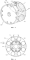
- FIGS. 2 and 3 are exploded perspective views for illustrating the configuration of an SEA according to an embodiment of the present invention.
- the SEA may include a motor-side rotation unit 100, a load-side rotation unit 200 and elastic members 310 and 320.
- the motor-side rotation unit 100 is coupled to a driving motor (not shown) and rotated by rotatory power of the driving motor.
- the load-side rotation unit 200 functions to transfer the rotatory power of the driving motor to a load.
- the motor-side rotation unit 100 and the load-side rotation unit 200 are coupled.
- the load-side rotation unit 200 may be configured to rotate in response to the rotation of the motor-side rotation unit 100.
- At least one pair of elastic members 300 is provided in the spaces between the motor-side rotation unit 100 and the load-side rotation unit 200.
- a frame having an accommodation spaces to which the at least one pair of elastic members 300 is fixed is formed in one of the motor-side rotation unit 100 and the load-side rotation unit 200 together rotated by the rotatory power of the driving motor.
- a frame for supporting the pair of elastic members therein may be formed in the other of the motor-side rotation unit 100 and the load-side rotation unit 200.
- any one of the elastic members may be compressed in the relative rotation direction of the motor-side rotation unit 100 on the basis of the load-side rotation unit 200, thereby being capable of implementing an SEA capable of force or torque control in a rotary motion.
- the SEA according to an embodiment of the present invention is suitable for a rotary motion and has a simple structure, and thus has an advantage in that it can be implemented in a small size.
- the elastic members 310 and 320 may be made of an elastic material, such as silicon or urethane, but the present invention is not limited thereto.
- the elastic members may be made of various elastic substances or a mixture of two or more elastic substances in addition to silicon and urethane.
- the elastic member 310, 320 may have a cylindrical shape as shown in FIG. 2 , but is not limited thereto.
- the elastic member may have various shapes in addition to the cylindrical shape.
- the material, shape or size of the elastic members 310 and 320 may be changed, and thus hardness K of the elastic member may vary.
- an inner frame 150 for supporting the pair of elastic members 300 therein may be formed in the motor-side rotation unit 100.
- An outer frame 250 for supporting the pair of elastic members 300 on the outside may be formed in the load-side rotation unit 200.
- accommodation spaces S in which the pair of elastic members 300 can be received and fixed by the outer frame 250 formed in the load-side rotation unit 200 may be provided in the load-side rotation unit 200.
- the elastic members 310 and 320 can be fixed to the spaces between the coupled motor-side rotation unit 100 and load-side rotation unit 200.
- the elastic members 310 and 320 may be compressed and fixed to the accommodation spaces S formed by the outer frame 250 of the load-side rotation unit 200.
- the elastic members 310 and 320 are supported by the inner frame 150 of the motor-side rotation unit 100 and the outer frame 250 of the load-side rotation unit 200 and compressed and fixed to the accommodation spaces S. Accordingly, the elastic members 310 and 320 may not need to be fixed to the motor-side rotation unit 100 or the load-side rotation unit 200 using a separate fixing member.
- the elastic members 310 and 320 are automatically separated, thereby being capable of facilitating the replacement of the elastic members 310 and 320.
- the SEA may further include a sensor part for measuring relative displacement between the motor-side rotation unit 100 and the load-side rotation unit 200.
- the sensor part may be configured to include a magnetic body 400 and a hall sensor 410 respectively formed at the corresponding positions of the motor-side rotation unit 100 and the load-side rotation unit 200.
- FIG. 4 is a diagram for illustrating an embodiment of the structure in which the elastic members 310 and 320 are fixed to the spaces between the motor-side rotation unit 100 and the load-side rotation unit 200. A description of an element that belongs to the illustrated elements and that is the same as that described with reference to FIGS. 2 and 3 is omitted hereunder.
- the pair of elastic members 300 may be fixed to the spaces between the inner frame 150 of the motor-side rotation unit 100 and the outer frame 250 of the load-side rotation unit 200 in the compressed state.
- Separated spaces D are present in the outside region of the SEA between the inner frame 150 of the motor-side rotation unit 100 and the outer frame 250 of the load-side rotation unit 200. A portion of the elastic members 310 and 320 may be exposed to the outside through the separated spaces.
- the separated spaces D may be used as reserved spaces for the perpendicular expansion of the elastic members 310 and 320.
- FIG. 4 four pairs of the elastic members (total of 8) have been illustrated as being formed in the SEA, but the present invention is not limited thereto. Three pairs or five pairs or more of the elastic members may be formed in the SEA, if necessary.
- the external force applied to the SEA may mean torque generated by rotatory power of the driving motor, torque generated by a force applied to the load side, or torque according to a reduction or addition between the torques.
- any one of the pair of elastic members 300 is compressed in the relative rotation direction of the motor-side rotation unit 100 with respect to the load-side rotation unit 200 (or the relative rotation direction of the load-side rotation unit 200 with respect to the motor-side rotation unit 100). Relative displacement corresponding to the compressed elastic members may occur.
- FIG. 5 The frames formed in the motor-side rotation unit 100 and the load-side rotation unit 200 are rotated, but have been illustrated as having displacement similar to a straight line in FIG. 5 , for convenience sake.
- the elastic members 310 and 320 may have been fixed to the spaces between the inner frame 150 and the outer frame 250 on the basis of a reference position R.
- the torque by the rotatory power of the driving motor may be calculated using Equation 1 below.
- ⁇ k ⁇ ⁇ ⁇ ⁇
- Equation 1 ⁇ is torque by the rotatory power of the driving motor, K is the hardness of the elastic member, and ⁇ is relative displacement for the reference position R.
- the torque ( ⁇ ) by the rotatory power of the driving motor may be calculated according to Equation 1.
- the torque by the rotatory power of the driving motor may be calculated based on the relative displacement ( ⁇ ) detected by the sensor part according to Equation 1.
- the torque ( ⁇ ) calculated using Equation 1 may indicate torque transferred to the load by the rotatory power of the driving motor.
- the operation of the SEA according to an embodiment of the present invention has been described above with reference to FIG. 5 by taking a case where torque is applied by the rotatory power of the driving motor in the state in which the load side has been fixed as an example, but the present invention is not limited thereto.
- torque is applied to the SEA by a force applied to the load side
- the SEA according to an embodiment of the present invention may operate as described above with reference to FIG. 5 .
- the torque ( ⁇ ) applied to the load side may be calculated based on the relative displacement ( ⁇ ) detected by the sensor part using Equation 1.
- the torque ( ⁇ ) calculated using Equation 1 may indicate a value, that is, the sum of a torque value applied to the load side and a torque value according to rotatory power of the driving motor.
- the magnetic body 400 for generating a magnetic field may be positioned in the motor-side rotation unit 100 and the hall sensor 410 may be positioned at a location of the load-side rotation unit 200 that faces the magnetic body 400.
- the hall sensor 410 may detect the direction and size of a magnetic field using a hall effect in which a voltage occurs in the direction perpendicular to current and the magnetic field when the magnetic field is applied to a conductor through which current flows.
- the direction and size of a magnetic field generated from the magnetic body 400 are measured using the output signal of the hall sensor 410.
- the relative rotation direction and displacement of the motor-side rotation unit 100 (or relative rotation direction and displacement of the load-side rotation unit 200) may be detected based on a result of the detection.
- FIGS. 7 and 8 are perspective views showing the configuration of an SEA according to another embodiment of the present invention. A description of an element and operation that belong to the illustrated elements and operation of the SEA and that are the same as those described with reference to FIGS. 2 to 6 is omitted hereunder.
- a driving motor 700 is coupled to the motor-side rotation unit 100 of the SEA, and a decelerator 720 and a decelerator fixing stage 730 may be additionally coupled to the motor-side rotation unit 100.
- a belt (or chain) and pulley for transferring rotatory power of the driving motor 700 to the motor-side rotation unit 100 may be provided in the SEA.
- a bearing 710 may be coupled to the load-side rotation unit 200 of the SEA.
- a bearing fixing stage 800 and a bearing cover 810 may be coupled the SEA coupled as shown in FIG. 7 .
- FIGS. 7 and 8 illustrate an embodiment of the configuration of the SEA coupled to the driving motor.
- An SEA according to an embodiment of the present invention is not limited to the SEA of FIGS. 7 and 8 . Some of the illustrated elements may be omitted or an additional element may be added, if necessary.
- a force (or torque) and position in the joint of a robot or other industrial machines may be together controlled using an SEA having a configuration, such as that described with reference to FIGS. 2 to 8 .
- a motion of a robot joint may be controlled using torque ( ⁇ ) calculated based on relative displacement ( ⁇ ) between the motor-side rotation unit 100 and the load-side rotation unit 200.
- an external force applied to the load side depending on relative displacement between the motor-side rotation unit 100 and the load-side rotation unit 200 may be detected.
- the control mode of the SEA may switch to torque control or position control based on a result of a comparison between the external force and a reference value.
- An SEA system may be configured to include an SEA having a configuration, such as that described with reference to FIGS. 2 to 8 , and a controller for controlling the SEA.
- FIG. 9 is a flowchart illustrating a method of controlling the SEA according to an embodiment of the present invention, and shows a method for the controller of the SEA system to control the operation of the SEA according to an embodiment of the present invention.
- the controller measures relative displacement between the motor-side rotation unit 100 and load-side rotation unit 200 of the SEA (step S900).
- relative displacement between the motor-side rotation unit 100 and the load-side rotation unit 200 may be measured using the magnetic body 400 and the hall sensor 410 respectively positioned at the corresponding positions of the motor-side rotation unit 100 and the load-side rotation unit 200.
- the controller calculates external torque by an external force applied to the load side based on the displacement measured at step S900 and hardness K of the elastic members provided in the SEA (step S910).
- torque ( ⁇ l ) may occur when external force (F l ) is applied to the load 1000 that does not rotate and maintains a current position, or torque ( ⁇ l ) may occur when external force (F l ) having a direction opposite the rotation direction of the load 1000 that rotates until it reaches a specific position is applied to the load 1000.
- torque ( ⁇ l ) may occur when external force (F l ) having the same direction as the rotation direction of the load 1000 is applied to the load 1000 that rotates.
- the external torque ( ⁇ l ) by the external force (F l ) applied to the load 1000 compresses any one of the pair of elastic members 310 and 320, so relative displacement between the motor-side rotation unit 100 and the load-side rotation unit 200 may occur.
- the external torque ( ⁇ l ) occurring due to the external force (F l ) may be calculated based on the relative displacement ( ⁇ ) between the motor-side rotation unit 100 and the load-side rotation unit 200 and the hardness K of the elastic members using Equation 1.
- the controller compares the external torque calculated at step S910 with preset critical torque (step S920), and switches the control mode of the SEA to torque control or position control based on a result of the comparison (step S930).
- the driving motor is controlled so that the load 1000 connected to the load-side rotation unit 200 of the SEA generates a given torque (or force).
- the controller may receive feedback for torque ( ⁇ e ) transferred to the load side, may compare the torque ( ⁇ e ) with reference torque ( ⁇ r ), and may control the driving motor.
- the controller may perform the torque control to control the driving motor so that the reference torque ( ⁇ r ) continues to be transferred to the load 1000 by performing pulse width modulation (PWM) control using Equation 2.
- PWM pulse width modulation
- Equation 2 F(s) indicates the torque control function of a PID controller, and KP, KD and KF indicate parameters for PID control.
- the controller may control driving motor using various known torque control methods.
- the driving motor is controlled so that the load 1000 coupled to the load-side rotation unit 200 of the SEA is moved as much as a given rotation angle (or position).
- the controller may receive the rotation angle ( ⁇ m ) of the motor-side output stage as feedback, may compare the received rotation angle ( ⁇ m ) with a reference angle ( ⁇ r ), and may control the driving motor.
- the controller may perform the position control to control the driving motor so that the load 1000 is rotated as much as the reference angle ( ⁇ r ) by performing PWM control using Equation 3 below.
- F s K P K F ⁇ r ⁇ ⁇ e + K D K F s ⁇ r ⁇ ⁇ e
- Equation 3 P(s) indicates the position control function of the PID controller, and KP and KD indicate parameters for PID control.
- the controller may control the driving motor using various known position control methods.
- Equation 4 shows an embodiment of a method for the controller to change the control mode of the SEA between the torque control and the position control based on a result of the comparison between the external torque ( ⁇ l ) and the critical torque ( ⁇ th ) at step S930.
- P s K P ⁇ r ⁇ ⁇ m + K D s ⁇ r ⁇ ⁇ m
- the controller may switch the control mode of the SEA to the position control.
- the controller may switch the control mode of the SEA to the torque control.
- the driving motor may generate torque having an opposite direction until the external torque ( ⁇ l ) reaches a critical torque ( ⁇ th ), so the position control is maintained.
- the position control may switch to the torque control.
- the torque control may switch to the position control, so the load 1000 returns to the original position by the rotation of the driving motor.
- the driving motor may continue to rotate the load 1000 until the external torque ( ⁇ l ) reaches the critical torque ( ⁇ th ), so the position control is maintained.
- the position control may switch to the torque control.
- the driving motor continues to rotate the load 1000 until the external torque ( ⁇ l ) reaches the critical torque ( ⁇ th ), so the position control is maintained.
- the position control may switch to the torque control.
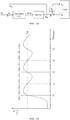
- oscillation may occur in a transition region near the critical torque ( ⁇ th ).
- the position control switches to the torque control at a point of time (t1) at which the external torque ( ⁇ l ) increases and exceeds the critical torque ( ⁇ th ). After the control mode switches to the torque control, torque ( ⁇ l ) may be reduced.
- the torque control switches to the position control again at a point of time (t2) at which the torque ( ⁇ l ) decreases and reaches the critical torque ( ⁇ th ). After the control mode switches to the position control, torque ( ⁇ l ) may increase.
- control mode repeatedly switches between the position control and the torque control in the transition region near the critical torque ( ⁇ th ), so oscillation may occur on the load side.
- the controller may operate so that the control mode of the SEA switches from the torque control to the position control.
- the control mode switches from the position control to the torque control. If the external torque ( ⁇ l ) decreases up to a value ( ⁇ th - ⁇ hys ) obtained by subtracting given torque from the critical torque, the control mode may switch to from the torque control to the position control.
- the position control switches to the torque control at a point of time (T1) at which the external torque ( ⁇ l ) increases and exceeds the critical torque ( ⁇ th ). After the control mode switches to the torque control, the torque ( ⁇ l ) may be decreased.
- the control mode does not switch and maintains the torque control. Accordingly, the torque ( ⁇ l ) transferred to the load 1000 may maintain a desired reference torque value.
- the torque control may switch to the position control.
- the frame having the accommodation spaces to which the pair of elastic members is fixed is formed in any one of the motor-side rotation unit and the load-side rotation unit rotated along with rotatory power of the driving motor. Accordingly, the SEA suitable for a rotary motion and having a simple structure can be provided because any one of the elastic members is compressed in the relative rotation direction of the motor-side rotation unit. Accordingly, a small-sized SEA can be implemented.
- an external force applied to the load side is detected based on relative displacement between the motor-side rotation unit and the load-side rotation unit.
- the control mode of the SEA switches to any one of the torque control and the position control based on a result of a comparison between an external force and a reference value. Accordingly, the SEA can stably control a force and position according to circumstances.
- the aforementioned methods according to the embodiments of the present invention may be produced in the form of a program to be executed by a computer.
- the program may be stored in a computer-readable recording medium.
- the computer-readable recording medium may include ROM, RAM, CD-ROM, a magnetic tape, a floppy disk, and an optical data storage device, for example.
- the computer-readable recording medium includes media implemented in the form of carrier waves (e.g., transmission through the Internet).
- the computer-readable recording medium may be distributed to computer systems connected over a network, and computer-readable code may be stored and executed in a distributed manner. Furthermore, a functional program, code and code segments for implementing the method may be easily reasoned by programmers those skilled in the art to which the present invention pertains.
Landscapes
- Engineering & Computer Science (AREA)
- Robotics (AREA)
- Mechanical Engineering (AREA)
- Power Engineering (AREA)
- Human Computer Interaction (AREA)
- Microelectronics & Electronic Packaging (AREA)
- Physics & Mathematics (AREA)
- Electromagnetism (AREA)
- Connection Of Motors, Electrical Generators, Mechanical Devices, And The Like (AREA)
- Control Of Electric Motors In General (AREA)
- Manipulator (AREA)
Applications Claiming Priority (3)
| Application Number | Priority Date | Filing Date | Title |
|---|---|---|---|
| KR1020170037706A KR101901167B1 (ko) | 2017-03-24 | 2017-03-24 | 직렬 탄성 액추에이터 장치 |
| KR1020170056191A KR101901168B1 (ko) | 2017-05-02 | 2017-05-02 | 직렬 탄성 액추에이터 제어 방법 및 그를 이용한 시스템 |
| PCT/KR2018/002564 WO2018174428A1 (ko) | 2017-03-24 | 2018-03-05 | 직렬 탄성 액추에이터 장치, 직렬 탄성 액추에이터 제어 방법 및 그를 이용한 시스템 |
Publications (3)
| Publication Number | Publication Date |
|---|---|
| EP3603901A1 true EP3603901A1 (de) | 2020-02-05 |
| EP3603901A4 EP3603901A4 (de) | 2020-04-15 |
| EP3603901B1 EP3603901B1 (de) | 2025-05-07 |
Family
ID=63585501
Family Applications (1)
| Application Number | Title | Priority Date | Filing Date |
|---|---|---|---|
| EP18759230.8A Active EP3603901B1 (de) | 2017-03-24 | 2018-03-05 | Serienelastisches stellglied , steuerungsverfahren für serienelastisches stellglied und system mit verwendung davon |
Country Status (5)
| Country | Link |
|---|---|
| US (1) | US11431222B2 (de) |
| EP (1) | EP3603901B1 (de) |
| JP (1) | JP7177698B2 (de) |
| CN (1) | CN109070344B (de) |
| WO (1) | WO2018174428A1 (de) |
Cited By (1)
| Publication number | Priority date | Publication date | Assignee | Title |
|---|---|---|---|---|
| EP4166723A1 (de) * | 2021-10-14 | 2023-04-19 | Yanmar Holdings Co., Ltd. | Antriebsvorrichtung und arbeitsmaschine |
Families Citing this family (6)
| Publication number | Priority date | Publication date | Assignee | Title |
|---|---|---|---|---|
| WO2019164037A1 (ko) * | 2018-02-23 | 2019-08-29 | (주)로보티즈 | 연성부를 갖는 액추에이터 모듈 |
| CN110480675B (zh) * | 2019-08-28 | 2021-03-30 | 王光远 | 一种压电式变刚度弹性关节 |
| CN110815254B (zh) * | 2019-12-06 | 2025-03-14 | 深圳优艾智合机器人科技有限公司 | 一种柔性结构、柔性连接件、执行机构、机械臂及机器人 |
| JP7721895B2 (ja) * | 2021-01-15 | 2025-08-13 | オムロン株式会社 | 駆動システム、制御方法および制御プログラム |
| JP7624850B2 (ja) * | 2021-03-05 | 2025-01-31 | 住友重機械工業株式会社 | ロボットアームの制御装置、制御方法、システム、及びプログラム |
| US12459793B2 (en) * | 2022-11-14 | 2025-11-04 | Hornet Acquisitionco, Llc | Method to detect homing loads in rescue hoist and winch assemblies |
Family Cites Families (20)
| Publication number | Priority date | Publication date | Assignee | Title |
|---|---|---|---|---|
| JPS58177253U (ja) * | 1982-05-22 | 1983-11-26 | 東芝機械株式会社 | 送りユニツト |
| JP2770982B2 (ja) * | 1989-05-25 | 1998-07-02 | 株式会社豊田中央研究所 | マニピユレータの位置と力の協調制御装置 |
| JPH07197941A (ja) * | 1993-12-30 | 1995-08-01 | Sanshin Ind Co Ltd | シャフトカップリング |
| US5650704A (en) * | 1995-06-29 | 1997-07-22 | Massachusetts Institute Of Technology | Elastic actuator for precise force control |
| JP3124519B2 (ja) * | 1998-07-23 | 2001-01-15 | セイコー精機株式会社 | 制御系のモード切替え機能を有するロボット制御装置 |
| JP2002059388A (ja) * | 2000-08-23 | 2002-02-26 | Sony Corp | 回転型アクチュエータおよび回転型アクチュエータを有する歩行ロボット |
| JP2002242950A (ja) * | 2000-12-12 | 2002-08-28 | Asa Denshi Kogyo Kk | 軸継手 |
| JP3961892B2 (ja) * | 2002-06-21 | 2007-08-22 | 株式会社アドバネクス | ロボット装置および緩衝装置 |
| JP2005319922A (ja) * | 2004-05-10 | 2005-11-17 | Koyo Seiko Co Ltd | 電動パワーステアリング装置 |
| GB2440753A (en) * | 2006-08-04 | 2008-02-13 | Univ Sussex | Force sensor and programmable spring emulator |
| JP2009066685A (ja) * | 2007-09-11 | 2009-04-02 | Sony Corp | ロボット装置及びロボット装置の制御方法 |
| JP2011083884A (ja) * | 2009-10-19 | 2011-04-28 | Yaskawa Electric Corp | 可変剛性機構及びロボット |
| US8525460B2 (en) | 2010-02-02 | 2013-09-03 | GM Global Technology Operations LLC | Architecture for robust force and impedance control of series elastic actuators |
| JP5483466B2 (ja) * | 2011-04-15 | 2014-05-07 | アサ電子工業株式会社 | カップリング |
| JP5907678B2 (ja) * | 2011-07-20 | 2016-04-26 | オリンパス株式会社 | 医療用動作機構およびマニピュレータ |
| US9079305B2 (en) * | 2012-08-28 | 2015-07-14 | Rethink Robotics, Inc. | Monitoring robot sensor consistency |
| CN103624797B (zh) * | 2013-12-16 | 2015-07-08 | 哈尔滨工业大学 | 一种旋转式可调刚度串联弹性机器人关节 |
| KR20150073791A (ko) * | 2013-12-23 | 2015-07-01 | 현대자동차주식회사 | 로봇용 안전관절장치 |
| CN105397808B (zh) * | 2015-12-15 | 2017-03-22 | 南开大学 | 基于压簧的线性串联弹性驱动器 |
| JP2016129488A (ja) * | 2016-03-30 | 2016-07-14 | アスモ株式会社 | 回転伝達装置及びモータ |
-
2018
- 2018-03-05 WO PCT/KR2018/002564 patent/WO2018174428A1/ko not_active Ceased
- 2018-03-05 CN CN201880000684.1A patent/CN109070344B/zh active Active
- 2018-03-05 JP JP2018532271A patent/JP7177698B2/ja active Active
- 2018-03-05 US US16/063,957 patent/US11431222B2/en active Active
- 2018-03-05 EP EP18759230.8A patent/EP3603901B1/de active Active
Cited By (1)
| Publication number | Priority date | Publication date | Assignee | Title |
|---|---|---|---|---|
| EP4166723A1 (de) * | 2021-10-14 | 2023-04-19 | Yanmar Holdings Co., Ltd. | Antriebsvorrichtung und arbeitsmaschine |
Also Published As
| Publication number | Publication date |
|---|---|
| EP3603901B1 (de) | 2025-05-07 |
| JP7177698B2 (ja) | 2022-11-24 |
| JP2020511910A (ja) | 2020-04-16 |
| US20210013773A1 (en) | 2021-01-14 |
| EP3603901A4 (de) | 2020-04-15 |
| CN109070344B (zh) | 2023-04-04 |
| WO2018174428A1 (ko) | 2018-09-27 |
| US11431222B2 (en) | 2022-08-30 |
| CN109070344A (zh) | 2018-12-21 |
Similar Documents
| Publication | Publication Date | Title |
|---|---|---|
| EP3603901A1 (de) | Serienelastisches stellglied , steuerungsverfahren für serienelastisches stellglied und system mit verwendung davon | |
| US6956346B2 (en) | Robot apparatus, and load absorbing apparatus and method | |
| US8661929B2 (en) | Device for generating stiffness and method for controlling stiffness and joint of robot manipulator comprising the same | |
| Mosadeghzad et al. | Comparison of various active impedance control approaches, modeling, implementation, passivity, stability and trade-offs | |
| Zhakatayev et al. | Closed-loop control of variable stiffness actuated robots via nonlinear model predictive control | |
| EP2390999B1 (de) | Verfahren zur Steuerung eines Vibrationsmotors | |
| US6989645B2 (en) | Robot apparatus, and load absorbing apparatus and method | |
| Sorrentino et al. | Physics-informed learning for the friction modeling of high-ratio harmonic drives | |
| KR101901167B1 (ko) | 직렬 탄성 액추에이터 장치 | |
| KR20180122301A (ko) | 직렬 탄성 액추에이터 제어 방법 및 그를 이용한 시스템 | |
| JP2006263832A (ja) | ロボットの制御装置 | |
| KR101901168B1 (ko) | 직렬 탄성 액추에이터 제어 방법 및 그를 이용한 시스템 | |
| Morito et al. | Reaction force observer using load dependent friction model | |
| Kawazawa et al. | High backdrivability control based on estimation of shaft torsion using load side angle sensor | |
| JP4789067B2 (ja) | システム同定装置およびそれを備えたモータ制御装置 | |
| JP2024120660A (ja) | アクチュエータ及びアクチュエータの制御方法 | |
| WO2023127652A1 (ja) | 把持装置及び把持装置の制御方法 | |
| Saranli et al. | Multi-point contact models for dynamic self-righting of a Hexapod | |
| US11298823B2 (en) | Sensor device and sensing method | |
| Wei et al. | WORKSPACE CONTROL OF TWO LINK PLANAR ROBOT USING MICRO-BOX 2000 | |
| Kondak et al. | Design of a robust high gain PID motion controller using sliding mode theory | |
| Ge et al. | Variable structure maneuvering control of a flexible spacecraft | |
| WO2023022194A1 (ja) | 把持装置及び把持装置の制御方法 | |
| WO2023181898A1 (ja) | 情報処理装置、情報処理方法、及び、移動体 | |
| Hieu et al. | A digital position controller of travelling wave ultrasonic motors |
Legal Events
| Date | Code | Title | Description |
|---|---|---|---|
| STAA | Information on the status of an ep patent application or granted ep patent |
Free format text: STATUS: UNKNOWN |
|
| STAA | Information on the status of an ep patent application or granted ep patent |
Free format text: STATUS: THE INTERNATIONAL PUBLICATION HAS BEEN MADE |
|
| PUAI | Public reference made under article 153(3) epc to a published international application that has entered the european phase |
Free format text: ORIGINAL CODE: 0009012 |
|
| STAA | Information on the status of an ep patent application or granted ep patent |
Free format text: STATUS: REQUEST FOR EXAMINATION WAS MADE |
|
| 17P | Request for examination filed |
Effective date: 20180906 |
|
| AK | Designated contracting states |
Kind code of ref document: A1 Designated state(s): AL AT BE BG CH CY CZ DE DK EE ES FI FR GB GR HR HU IE IS IT LI LT LU LV MC MK MT NL NO PL PT RO RS SE SI SK SM TR |
|
| AX | Request for extension of the european patent |
Extension state: BA ME |
|
| A4 | Supplementary search report drawn up and despatched |
Effective date: 20200317 |
|
| RIC1 | Information provided on ipc code assigned before grant |
Ipc: B25J 19/00 20060101ALI20200311BHEP Ipc: B25J 13/08 20060101ALI20200311BHEP Ipc: H02K 7/00 20060101ALI20200311BHEP Ipc: H02K 11/215 20160101ALI20200311BHEP Ipc: B25J 9/12 20060101AFI20200311BHEP Ipc: B25J 9/00 20060101ALI20200311BHEP Ipc: B25J 9/16 20060101ALI20200311BHEP Ipc: B25J 19/02 20060101ALI20200311BHEP |
|
| DAV | Request for validation of the european patent (deleted) | ||
| DAX | Request for extension of the european patent (deleted) | ||
| STAA | Information on the status of an ep patent application or granted ep patent |
Free format text: STATUS: EXAMINATION IS IN PROGRESS |
|
| 17Q | First examination report despatched |
Effective date: 20220704 |
|
| GRAP | Despatch of communication of intention to grant a patent |
Free format text: ORIGINAL CODE: EPIDOSNIGR1 |
|
| STAA | Information on the status of an ep patent application or granted ep patent |
Free format text: STATUS: GRANT OF PATENT IS INTENDED |
|
| INTG | Intention to grant announced |
Effective date: 20241128 |
|
| GRAS | Grant fee paid |
Free format text: ORIGINAL CODE: EPIDOSNIGR3 |
|
| GRAA | (expected) grant |
Free format text: ORIGINAL CODE: 0009210 |
|
| STAA | Information on the status of an ep patent application or granted ep patent |
Free format text: STATUS: THE PATENT HAS BEEN GRANTED |
|
| AK | Designated contracting states |
Kind code of ref document: B1 Designated state(s): AL AT BE BG CH CY CZ DE DK EE ES FI FR GB GR HR HU IE IS IT LI LT LU LV MC MK MT NL NO PL PT RO RS SE SI SK SM TR |
|
| REG | Reference to a national code |
Ref country code: GB Ref legal event code: FG4D |
|
| REG | Reference to a national code |
Ref country code: CH Ref legal event code: EP |
|
| REG | Reference to a national code |
Ref country code: DE Ref legal event code: R096 Ref document number: 602018081729 Country of ref document: DE |
|
| REG | Reference to a national code |
Ref country code: IE Ref legal event code: FG4D |
|
| REG | Reference to a national code |
Ref country code: NL Ref legal event code: MP Effective date: 20250507 |
|
| PG25 | Lapsed in a contracting state [announced via postgrant information from national office to epo] |
Ref country code: PT Free format text: LAPSE BECAUSE OF FAILURE TO SUBMIT A TRANSLATION OF THE DESCRIPTION OR TO PAY THE FEE WITHIN THE PRESCRIBED TIME-LIMIT Effective date: 20250908 Ref country code: ES Free format text: LAPSE BECAUSE OF FAILURE TO SUBMIT A TRANSLATION OF THE DESCRIPTION OR TO PAY THE FEE WITHIN THE PRESCRIBED TIME-LIMIT Effective date: 20250507 Ref country code: FI Free format text: LAPSE BECAUSE OF FAILURE TO SUBMIT A TRANSLATION OF THE DESCRIPTION OR TO PAY THE FEE WITHIN THE PRESCRIBED TIME-LIMIT Effective date: 20250507 |
|
| REG | Reference to a national code |
Ref country code: LT Ref legal event code: MG9D |
|
| PG25 | Lapsed in a contracting state [announced via postgrant information from national office to epo] |
Ref country code: GR Free format text: LAPSE BECAUSE OF FAILURE TO SUBMIT A TRANSLATION OF THE DESCRIPTION OR TO PAY THE FEE WITHIN THE PRESCRIBED TIME-LIMIT Effective date: 20250808 Ref country code: NO Free format text: LAPSE BECAUSE OF FAILURE TO SUBMIT A TRANSLATION OF THE DESCRIPTION OR TO PAY THE FEE WITHIN THE PRESCRIBED TIME-LIMIT Effective date: 20250807 |
|
| PG25 | Lapsed in a contracting state [announced via postgrant information from national office to epo] |
Ref country code: NL Free format text: LAPSE BECAUSE OF FAILURE TO SUBMIT A TRANSLATION OF THE DESCRIPTION OR TO PAY THE FEE WITHIN THE PRESCRIBED TIME-LIMIT Effective date: 20250507 Ref country code: PL Free format text: LAPSE BECAUSE OF FAILURE TO SUBMIT A TRANSLATION OF THE DESCRIPTION OR TO PAY THE FEE WITHIN THE PRESCRIBED TIME-LIMIT Effective date: 20250507 |
|
| REG | Reference to a national code |
Ref country code: AT Ref legal event code: MK05 Ref document number: 1791973 Country of ref document: AT Kind code of ref document: T Effective date: 20250507 |
|
| PG25 | Lapsed in a contracting state [announced via postgrant information from national office to epo] |
Ref country code: BG Free format text: LAPSE BECAUSE OF FAILURE TO SUBMIT A TRANSLATION OF THE DESCRIPTION OR TO PAY THE FEE WITHIN THE PRESCRIBED TIME-LIMIT Effective date: 20250507 |
|
| PG25 | Lapsed in a contracting state [announced via postgrant information from national office to epo] |
Ref country code: HR Free format text: LAPSE BECAUSE OF FAILURE TO SUBMIT A TRANSLATION OF THE DESCRIPTION OR TO PAY THE FEE WITHIN THE PRESCRIBED TIME-LIMIT Effective date: 20250507 |
|
| PG25 | Lapsed in a contracting state [announced via postgrant information from national office to epo] |
Ref country code: AT Free format text: LAPSE BECAUSE OF FAILURE TO SUBMIT A TRANSLATION OF THE DESCRIPTION OR TO PAY THE FEE WITHIN THE PRESCRIBED TIME-LIMIT Effective date: 20250507 |
|
| PG25 | Lapsed in a contracting state [announced via postgrant information from national office to epo] |
Ref country code: RS Free format text: LAPSE BECAUSE OF FAILURE TO SUBMIT A TRANSLATION OF THE DESCRIPTION OR TO PAY THE FEE WITHIN THE PRESCRIBED TIME-LIMIT Effective date: 20250807 |
|
| PG25 | Lapsed in a contracting state [announced via postgrant information from national office to epo] |
Ref country code: IS Free format text: LAPSE BECAUSE OF FAILURE TO SUBMIT A TRANSLATION OF THE DESCRIPTION OR TO PAY THE FEE WITHIN THE PRESCRIBED TIME-LIMIT Effective date: 20250907 |
|
| PG25 | Lapsed in a contracting state [announced via postgrant information from national office to epo] |
Ref country code: LV Free format text: LAPSE BECAUSE OF FAILURE TO SUBMIT A TRANSLATION OF THE DESCRIPTION OR TO PAY THE FEE WITHIN THE PRESCRIBED TIME-LIMIT Effective date: 20250507 |
|
| PG25 | Lapsed in a contracting state [announced via postgrant information from national office to epo] |
Ref country code: DK Free format text: LAPSE BECAUSE OF FAILURE TO SUBMIT A TRANSLATION OF THE DESCRIPTION OR TO PAY THE FEE WITHIN THE PRESCRIBED TIME-LIMIT Effective date: 20250507 Ref country code: SM Free format text: LAPSE BECAUSE OF FAILURE TO SUBMIT A TRANSLATION OF THE DESCRIPTION OR TO PAY THE FEE WITHIN THE PRESCRIBED TIME-LIMIT Effective date: 20250507 |
|
| PG25 | Lapsed in a contracting state [announced via postgrant information from national office to epo] |
Ref country code: CZ Free format text: LAPSE BECAUSE OF FAILURE TO SUBMIT A TRANSLATION OF THE DESCRIPTION OR TO PAY THE FEE WITHIN THE PRESCRIBED TIME-LIMIT Effective date: 20250507 |
|
| PG25 | Lapsed in a contracting state [announced via postgrant information from national office to epo] |
Ref country code: EE Free format text: LAPSE BECAUSE OF FAILURE TO SUBMIT A TRANSLATION OF THE DESCRIPTION OR TO PAY THE FEE WITHIN THE PRESCRIBED TIME-LIMIT Effective date: 20250507 |
|
| PG25 | Lapsed in a contracting state [announced via postgrant information from national office to epo] |
Ref country code: RO Free format text: LAPSE BECAUSE OF FAILURE TO SUBMIT A TRANSLATION OF THE DESCRIPTION OR TO PAY THE FEE WITHIN THE PRESCRIBED TIME-LIMIT Effective date: 20250507 Ref country code: SK Free format text: LAPSE BECAUSE OF FAILURE TO SUBMIT A TRANSLATION OF THE DESCRIPTION OR TO PAY THE FEE WITHIN THE PRESCRIBED TIME-LIMIT Effective date: 20250507 |
|
| REG | Reference to a national code |
Ref country code: DE Ref legal event code: R097 Ref document number: 602018081729 Country of ref document: DE |
|
| PLBE | No opposition filed within time limit |
Free format text: ORIGINAL CODE: 0009261 |
|
| STAA | Information on the status of an ep patent application or granted ep patent |
Free format text: STATUS: NO OPPOSITION FILED WITHIN TIME LIMIT |
|
| REG | Reference to a national code |
Ref country code: CH Ref legal event code: L10 Free format text: ST27 STATUS EVENT CODE: U-0-0-L10-L00 (AS PROVIDED BY THE NATIONAL OFFICE) Effective date: 20260318 |