EP3603901B1 - Serienelastisches stellglied , steuerungsverfahren für serienelastisches stellglied und system mit verwendung davon - Google Patents
Serienelastisches stellglied , steuerungsverfahren für serienelastisches stellglied und system mit verwendung davon Download PDFInfo
- Publication number
- EP3603901B1 EP3603901B1 EP18759230.8A EP18759230A EP3603901B1 EP 3603901 B1 EP3603901 B1 EP 3603901B1 EP 18759230 A EP18759230 A EP 18759230A EP 3603901 B1 EP3603901 B1 EP 3603901B1
- Authority
- EP
- European Patent Office
- Prior art keywords
- rotation unit
- side rotation
- load
- torque
- motor
- Prior art date
- Legal status (The legal status is an assumption and is not a legal conclusion. Google has not performed a legal analysis and makes no representation as to the accuracy of the status listed.)
- Active
Links
Images
Classifications
-
- H—ELECTRICITY
- H02—GENERATION; CONVERSION OR DISTRIBUTION OF ELECTRIC POWER
- H02K—DYNAMO-ELECTRIC MACHINES
- H02K7/00—Arrangements for handling mechanical energy structurally associated with dynamo-electric machines, e.g. structural association with mechanical driving motors or auxiliary dynamo-electric machines
- H02K7/003—Couplings; Details of shafts
-
- B—PERFORMING OPERATIONS; TRANSPORTING
- B25—HAND TOOLS; PORTABLE POWER-DRIVEN TOOLS; MANIPULATORS
- B25J—MANIPULATORS; CHAMBERS PROVIDED WITH MANIPULATION DEVICES
- B25J13/00—Controls for manipulators
- B25J13/08—Controls for manipulators by means of sensing devices, e.g. viewing or touching devices
- B25J13/085—Force or torque sensors
-
- B—PERFORMING OPERATIONS; TRANSPORTING
- B25—HAND TOOLS; PORTABLE POWER-DRIVEN TOOLS; MANIPULATORS
- B25J—MANIPULATORS; CHAMBERS PROVIDED WITH MANIPULATION DEVICES
- B25J19/00—Accessories fitted to manipulators, e.g. for monitoring, for viewing; Safety devices combined with or specially adapted for use in connection with manipulators
- B25J19/02—Sensing devices
- B25J19/027—Electromagnetic sensing devices
-
- B—PERFORMING OPERATIONS; TRANSPORTING
- B25—HAND TOOLS; PORTABLE POWER-DRIVEN TOOLS; MANIPULATORS
- B25J—MANIPULATORS; CHAMBERS PROVIDED WITH MANIPULATION DEVICES
- B25J9/00—Program-controlled manipulators
-
- B—PERFORMING OPERATIONS; TRANSPORTING
- B25—HAND TOOLS; PORTABLE POWER-DRIVEN TOOLS; MANIPULATORS
- B25J—MANIPULATORS; CHAMBERS PROVIDED WITH MANIPULATION DEVICES
- B25J9/00—Program-controlled manipulators
- B25J9/10—Program-controlled manipulators characterised by positioning means for manipulator elements
- B25J9/12—Program-controlled manipulators characterised by positioning means for manipulator elements electric
- B25J9/126—Rotary actuators
-
- H—ELECTRICITY
- H02—GENERATION; CONVERSION OR DISTRIBUTION OF ELECTRIC POWER
- H02K—DYNAMO-ELECTRIC MACHINES
- H02K11/00—Structural association of dynamo-electric machines with electric components or with devices for shielding, monitoring or protection
- H02K11/20—Structural association of dynamo-electric machines with electric components or with devices for shielding, monitoring or protection for measuring, monitoring, testing, protecting or switching
- H02K11/21—Devices for sensing speed or position, or actuated thereby
- H02K11/215—Magnetic effect devices, e.g. Hall-effect or magneto-resistive elements
-
- H—ELECTRICITY
- H02—GENERATION; CONVERSION OR DISTRIBUTION OF ELECTRIC POWER
- H02K—DYNAMO-ELECTRIC MACHINES
- H02K7/00—Arrangements for handling mechanical energy structurally associated with dynamo-electric machines, e.g. structural association with mechanical driving motors or auxiliary dynamo-electric machines
Definitions
- the present invention relates to the structure of a series elastic actuator (hereinafter referred to as an "SEA") and a method of controlling the same.
- SEA series elastic actuator
- the intelligent robot In order to develop the intelligent robot, advanced technologies, such as new materials, semiconductors, artificial robots and sensor software, in addition to the traditional technologies, such as machines and electronics, are necessary. Unlike the existing industrial robot, the intelligent robot may be said to be a robot having functions and performance required for the future market.
- the intelligent robot can perform various tasks at places closer to humans. It is necessary to apply a series elastic actuator (SEA) technology to the robot so as to solve a problem that may occur in a cooperation process with humans.
- SEA series elastic actuator
- the SEA is a technology for controlling a force and position using elasticity.
- the SEA controls not only a position like a robot joint, but both a position and force like the muscle of human, and thus enables a robot to operate in a rough place like an uneven ground or adaptively operate in response to external pressure.
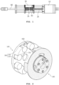
- the SEA has various types, but a bolt-driven SEA having a structure shown in FIG. 1 is commonly used.
- a conventional bolt-driven SEA includes a bolt screw 20 rotatably coupled to a driving motor 10, a nut part 30 performing a rectilinear motion left or right in the rotation direction of the bolt screw 20, a rectilinear motion part 50 performing a rectilinear motion left or right through a spring 40 supporting the nut part 30, and an arm 60 coupled to the rectilinear motion part 50.
- the bolt screw 20 is directly coupled to the driving motor 10 and rotated.
- the nut part 30 coupled to the bolt screw 20 performs a rectilinear motion left or right in the rotation direction of the bolt screw 20.
- the rectilinear motion part 50 and the arm 60 perform a rectilinear motion in the same direction as the nut part 30 through the nut part 30 and the spring 40 supporting the nut part.
- Such a conventional SEA has disadvantages in that the structure is complicated and the size is large because the entire rectilinear motion part including the spring must be designed to move.
- WO 2008/015460 discloses A force transducer, having first and second members which are coupled such as to be movable in one axis relative to one another; and a deformable elastic element which is disposed between the first and second members, such that a force as applied to one of the first and second members causes deformation of the elastic element and is transferred to the other of the first and second members, with the relative deflection of the first and second members corresponding to the applied force.
- JP 2004 025319 discloses a robotic device and a shock absorber to buffer only an excessive torque while transmitting a proper torque.
- US 5 650 704 A discloses an elastic actuator consisting of a motor and a motor drive transmission connected at an output of the motor.
- An elastic element is connected in series with the motor drive transmission, and this elastic element is positioned to alone support the full weight of any load connected at an output of the actuator.
- a single force transducer is positioned at a point between a mount for the motor and an output of the actuator. This force transducer generates a force signal, based on deflection of the elastic element, that indicates force applied by the elastic element to an output of the actuator.
- An active feedback force control loop is connected between the force transducer and the motor for controlling the motor. This motor control is based on the force signal to deflect the elastic element an amount that produces a desired actuator output force.
- the produced output force is substantially independent of load motion.
- the invention also provides a torsional spring consisting of a flexible structure having at least three flat sections each connected integrally with and extending radially from a central section. Each flat section extends axially along the central section from a distal end of the central section to a proximal end of the central section.
- US 2009/069942 discloses a robot apparatus having a multi-link structure including a plurality of links and joints serving as link movable sections, and in which at least some of the links are driven by combination of position control and force control is disclosed.
- the apparatus includes: position control means for performing the position control on the links, which are driven by position control and force control; position control means with force constraint for placing the force control before the position control so as not to cause the magnitude of an external force to exceed a set value; force control means for performing the force control on the links; and integrated force/position control means for controlling driving of the joints by switching the position control means, the position control means with force constraint, and the force control means, and unifies the position control and the force control.
- GB 2 235 067 A discloses that a force and moment which a manipulator receives from an external environment is detected, and this detected value is multiplied by a gain inversely proportional to a virtual spring constant set by a tool coordinate system, and the product is further converted to a value in each joint coordinate system of the manipulator so as to determine a detection torque.
- a command value of force and moment is converted to a value in each joint coordinate value of the manipulator in the same way as described above, so as to determine a command torque.
- a difference between a position command value and a position detection value is multiplied by a virtual spring constant in each joint coordinate system of the manipulator obtained by converting the virtual spring constant, and a differential torque is obtained by converting the aforementioned difference to a force and moment corresponding to the difference.
- a targeted torque is determined by adding the command torque and the differential torque, and feedback control is affected such that the detected torque of each joint of the manipulator coincides with the targeted torque.
- US 6 294 890 B1 discloses that a robot controller is provided which can smoothly switch the mode between a position control in a free space and a position or force control to a contact surface.
- the present invention has been made keeping in mind the above problems occurring in the prior art, and an object of the present invention is to provide an SEA having a structure capable of an efficient operation.
- an object of the present invention is to provide a method of controlling an SEA having a structure suitable for a rotary motion and an SEA system using the same.
- An embodiment of the present invention include a motor-side rotation unit coupled to a driving motor and rotated by rotatory power of the driving motor, a load-side rotation unit coupled to the motor-side rotation unit to transfer the rotatory power of the driving motor to a load, and at least one pair of elastic members provided in spaces between the motor-side rotation unit and the load-side rotation unit, wherein a frame having accommodation spaces to which the pair of elastic members is fixed is formed in any one of the motor-side rotation unit and the load-side rotation unit.
- a series elastic actuator includes a motor-side rotation unit coupled to a driving motor and rotated by rotatory power of the driving motor, a load-side rotation unit coupled to the motor-side rotation unit to transfer the rotatory power of the driving motor to a load, and at least one pair of elastic members fixed to spaces between the motor-side rotation unit and the load-side rotation unit.
- a first frame for supporting the pair of elastic members therein is formed in the motor-side rotation unit, and a second frame for supporting the pair of elastic members on the outside is formed in the load-side rotation unit.
- An embodiment of the present invention includes controlling a series elastic actuator (SEA) including a motor-side rotation unit and load-side rotation unit coupled to transfer rotatory power of a driving motor to a load and elastic members.
- the method includes measuring relative displacement between the motor-side rotation unit and the load-side rotation unit, calculating external torque by an external force applied to the load side based on the measured displacement and hardness (K) of the elastic member, comparing the calculated external torque with a critical torque, and switching a control mode of the SEA to any one of torque control and position control based on a result of the comparison.
- SEA series elastic actuator
- K hardness
- the control mode switches from the position control to the torque control.
- the control mode switches from the torque control to the position control.
- the steps of the control method may be configured in a computer program form so that they are executed in an SEA system according to an embodiment of the present invention.
- the corresponding computer program may be stored in a computer-readable medium.
- a series elastic actuator system includes a motor-side rotation unit coupled to a driving motor and rotated by rotatory power of the driving motor, a load-side rotation unit coupled to the motor-side rotation unit to transfer the rotatory power of the driving motor to a load, and at least one pair of elastic members provided in spaces between the motor-side rotation unit and the load-side rotation unit, a sensor part configured to measure relative displacement between the motor-side rotation unit and the load-side rotation unit, and a controller configured to calculate external torque by an external force applied to the load side using the measured displacement and switch a control mode to any one of torque control and position control based on a result of a comparison between the calculated external torque and a critical torque.
- processors or the functions of various devices illustrated in the drawings that include function blocks illustrated as a similar concept may be provided by the use of hardware capable of executing software in relation to proper software, in addition to dedicated hardware.
- the function may be provided by a single dedicated processor, a single sharing processor, or a plurality of separated processors, and some of them may be shared.
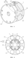
- FIGS. 2 and 3 are exploded perspective views for illustrating the configuration of an SEA according to an embodiment of the present invention.
- the SEA includes a motor-side rotation unit 100, a load-side rotation unit 200 and elastic members 310 and 320.
- the motor-side rotation unit 100 is coupled to a driving motor (not shown) and rotated by rotatory power of the driving motor.
- the load-side rotation unit 200 functions to transfer the rotatory power of the driving motor to a load.
- the motor-side rotation unit 100 and the load-side rotation unit 200 are coupled.
- the load-side rotation unit 200 may be configured to rotate in response to the rotation of the motor-side rotation unit 100.
- At least one pair of elastic members 300 is provided in the spaces between the motor-side rotation unit 100 and the load-side rotation unit 200.
- a frame having accommodation spaces to which the at least one pair of elastic members 300 is fixed is formed in one of the motor-side rotation unit 100 and the load-side rotation unit 200 together rotated by the rotatory power of the driving motor.
- a frame for supporting the pair of elastic members therein is formed in the other of the motor-side rotation unit 100 and the load-side rotation unit 200.
- any one of the elastic members may be compressed in the relative rotation direction of the motor-side rotation unit 100 on the basis of the load-side rotation unit 200, thereby being capable of implementing an SEA capable of force or torque control in a rotary motion.
- the SEA according to an embodiment of the present invention is suitable for a rotary motion and has a simple structure, and thus has an advantage in that it can be implemented in a small size.
- the elastic members 310 and 320 may be made of an elastic material, such as silicon or urethane, but the present invention is not limited thereto.
- the elastic members may be made of various elastic substances or a mixture of two or more elastic substances in addition to silicon and urethane.
- the elastic member 310, 320 may have a cylindrical shape as shown in FIG. 2 , but is not limited thereto.
- the elastic member may have various shapes in addition to the cylindrical shape.
- the material, shape or size of the elastic members 310 and 320 may be changed, and thus hardness K of the elastic member may vary.
- an inner frame 150 for supporting the pair of elastic members 300 therein is formed in the motor-side rotation unit 100.
- An outer frame 250 for supporting the pair of elastic members 300 on the outside may be formed in the load-side rotation unit 200.
- accommodation spaces S in which the pair of elastic members 300 can be received and fixed by the outer frame 250 formed in the load-side rotation unit 200 may be provided in the load-side rotation unit 200.
- the elastic members 310 and 320 can be fixed to the spaces between the coupled motor-side rotation unit 100 and load-side rotation unit 200.
- the elastic members 310 and 320 may be compressed and fixed to the accommodation spaces S formed by the outer frame 250 of the load-side rotation unit 200.
- the elastic members 310 and 320 are supported by the inner frame 150 of the motor-side rotation unit 100 and the outer frame 250 of the load-side rotation unit 200 and compressed and fixed to the accommodation spaces S. Accordingly, the elastic members 310 and 320 may not need to be fixed to the motor-side rotation unit 100 or the load-side rotation unit 200 using a separate fixing member.
- the elastic members 310 and 320 are automatically separated, thereby being capable of facilitating the replacement of the elastic members 310 and 320.
- the SEA according to an embodiment of the present invention further includes a sensor part for measuring relative displacement between the motor-side rotation unit 100 and the load-side rotation unit 200.
- the sensor part is configured to include a magnetic body 400 and a hall sensor 410 respectively formed at the corresponding positions of the motor-side rotation unit 100 and the load-side rotation unit 200.
- FIG. 4 is a diagram for illustrating an embodiment of the structure in which the elastic members 310 and 320 are fixed to the spaces between the motor-side rotation unit 100 and the load-side rotation unit 200. A description of an element that belongs to the illustrated elements and that is the same as that described with reference to FIGS. 2 and 3 is omitted hereunder.
- the pair of elastic members 300 may be fixed to the spaces between the inner frame 150 of the motor-side rotation unit 100 and the outer frame 250 of the load-side rotation unit 200 in the compressed state.
- Separated spaces D are present in the outside region of the SEA between the inner frame 150 of the motor-side rotation unit 100 and the outer frame 250 of the load-side rotation unit 200. A portion of the elastic members 310 and 320 may be exposed to the outside through the separated spaces.
- the separated spaces D may be used as reserved spaces for the perpendicular expansion of the elastic members 310 and 320.
- FIG. 4 four pairs of the elastic members (total of 8) have been illustrated as being formed in the SEA, but the present invention is not limited thereto. Three pairs or five pairs or more of the elastic members may be formed in the SEA, if necessary.
- the external force applied to the SEA may mean torque generated by rotatory power of the driving motor, torque generated by a force applied to the load side, or torque according to a reduction or addition between the torques.
- any one of the pair of elastic members 300 is compressed in the relative rotation direction of the motor-side rotation unit 100 with respect to the load-side rotation unit 200 (or the relative rotation direction of the load-side rotation unit 200 with respect to the motor-side rotation unit 100). Relative displacement corresponding to the compressed elastic members may occur.
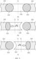
- FIG. 5 The frames formed in the motor-side rotation unit 100 and the load-side rotation unit 200 are rotated, but have been illustrated as having displacement similar to a straight line in FIG. 5 , for convenience sake.
- the elastic members 310 and 320 may have been fixed to the spaces between the inner frame 150 and the outer frame 250 on the basis of a reference position R.
- the torque by the rotatory power of the driving motor may be calculated using Equation 1 below.
- ⁇ k ⁇ ⁇
- Equation 1 ⁇ is torque by the rotatory power of the driving motor, K is the hardness of the elastic member, and ⁇ is relative displacement for the reference position R.
- the torque ( ⁇ ) by the rotatory power of the driving motor may be calculated according to Equation 1.
- the torque by the rotatory power of the driving motor may be calculated based on the relative displacement ( ⁇ ) detected by the sensor part according to Equation 1.
- the torque ( ⁇ ) calculated using Equation 1 may indicate torque transferred to the load by the rotatory power of the driving motor.
- the operation of the SEA according to an embodiment of the present invention has been described above with reference to FIG. 5 by taking a case where torque is applied by the rotatory power of the driving motor in the state in which the load side has been fixed as an example, but the present invention is not limited thereto.
- torque is applied to the SEA by a force applied to the load side
- the SEA according to an embodiment of the present invention may operate as described above with reference to FIG. 5 .
- the torque ( ⁇ ) applied to the load side may be calculated based on the relative displacement ( ⁇ ) detected by the sensor part using Equation 1.
- the torque ( ⁇ ) calculated using Equation 1 may indicate a value, that is, the sum of a torque value applied to the load side and a torque value according to rotatory power of the driving motor.
- the magnetic body 400 for generating a magnetic field may be positioned in the motor-side rotation unit 100 and the hall sensor 410 may be positioned at a location of the load-side rotation unit 200 that faces the magnetic body 400.
- the hall sensor 410 may detect the direction and size of a magnetic field using a hall effect in which a voltage occurs in the direction perpendicular to current and the magnetic field when the magnetic field is applied to a conductor through which current flows.
- the direction and size of a magnetic field generated from the magnetic body 400 are measured using the output signal of the hall sensor 410.
- the relative rotation direction and displacement of the motor-side rotation unit 100 (or relative rotation direction and displacement of the load-side rotation unit 200) may be detected based on a result of the detection.
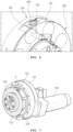
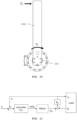
- FIGS. 7 and 8 are perspective views showing the configuration of an SEA according to another embodiment of the present invention. A description of an element and operation that belong to the illustrated elements and operation of the SEA and that are the same as those described with reference to FIGS. 2 to 6 is omitted hereunder.
- a driving motor 700 is coupled to the motor-side rotation unit 100 of the SEA, and a decelerator 720 and a decelerator fixing stage 730 may be additionally coupled to the motor-side rotation unit 100.
- a belt (or chain) and pulley for transferring rotatory power of the driving motor 700 to the motor-side rotation unit 100 may be provided in the SEA.
- a bearing 710 may be coupled to the load-side rotation unit 200 of the SEA.
- a bearing fixing stage 800 and a bearing cover 810 may be coupled the SEA coupled as shown in FIG. 7 .
- FIGS. 7 and 8 illustrate an embodiment of the configuration of the SEA coupled to the driving motor.
- An SEA according to an embodiment of the present invention is not limited to the SEA of FIGS. 7 and 8 . Some of the illustrated elements may be omitted or an additional element may be added, if necessary.
- a force (or torque) and position in the joint of a robot or other industrial machines may be together controlled using an SEA having a configuration, such as that described with reference to FIGS. 2 to 8 .
- a motion of a robot joint may be controlled using torque ( ⁇ ) calculated based on relative displacement ( ⁇ ) between the motor-side rotation unit 100 and the load-side rotation unit 200.
- an external force applied to the load side depending on relative displacement between the motor-side rotation unit 100 and the load-side rotation unit 200 may be detected.
- the control mode of the SEA may switch to torque control or position control based on a result of a comparison between the external force and a reference value.
- An SEA system may be configured to include an SEA having a configuration, such as that described with reference to FIGS. 2 to 8 , and a controller for controlling the SEA.
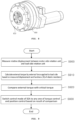
- FIG. 9 is a flowchart illustrating a method of controlling the SEA according to various aspects, and shows a method for the controller of the SEA system to control the operation of the SEA according to an embodiment of the present invention.
- step S900 relative displacement between the motor-side rotation unit 100 and the load-side rotation unit 200 is measured using the magnetic body 400 and the hall sensor 410 respectively positioned at the corresponding positions of the motor-side rotation unit 100 and the load-side rotation unit 200.
- torque ( ⁇ l ) may occur when external force (F l ) is applied to the load 1000 that does not rotate and maintains a current position, or torque ( ⁇ l ) may occur when external force (F l ) having a direction opposite the rotation direction of the load 1000 that rotates until it reaches a specific position is applied to the load 1000.
- torque ( ⁇ l ) may occur when external force (F l ) having the same direction as the rotation direction of the load 1000 is applied to the load 1000 that rotates.
- the external torque ( ⁇ l ) by the external force (F l ) applied to the load 1000 compresses any one of the pair of elastic members 310 and 320, so relative displacement between the motor-side rotation unit 100 and the load-side rotation unit 200 may occur.
- the external torque ( ⁇ l ) occurring due to the external force (F l ) may be calculated based on the relative displacement ( ⁇ ) between the motor-side rotation unit 100 and the load-side rotation unit 200 and the hardness K of the elastic members using Equation 1.
- the controller compares the external torque calculated at step S910 with preset critical torque (step S920), and switches the control mode of the SEA to torque control or position control based on a result of the comparison (step S930).
- the driving motor is controlled so that the load 1000 connected to the load-side rotation unit 200 of the SEA generates a given torque (or force).
- the controller may receive feedback for torque ( ⁇ e ) transferred to the load side, may compare the torque ( ⁇ e ) with reference torque ( ⁇ r ), and may control the driving motor.
- the controller may perform the torque control to control the driving motor so that the reference torque ( ⁇ r ) continues to be transferred to the load 1000 by performing pulse width modulation (PWM) control using Equation 2.
- PWM pulse width modulation
- Equation 2 F(s) indicates the torque control function of a PID controller, and KP, KD and KF indicate parameters for PID control.
- the controller may control driving motor using various known torque control methods.
- the driving motor is controlled so that the load 1000 coupled to the load-side rotation unit 200 of the SEA is moved as much as a given rotation angle (or position).
- the controller may receive the rotation angle ( ⁇ m ) of the motor-side output stage as feedback, may compare the received rotation angle ( ⁇ m ) with a reference angle ( ⁇ r ), and may control the driving motor.
- the controller may perform the position control to control the driving motor so that the load 1000 is rotated as much as the reference angle ( ⁇ r ) by performing PWM control using Equation 3 below.
- F s K P K F ⁇ r ⁇ ⁇ e + K D K F s ⁇ r ⁇ ⁇ e
- Equation 3 P(s) indicates the position control function of the PID controller, and KP and KD indicate parameters for PID control.
- the controller may control the driving motor using various known position control methods.
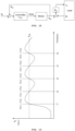
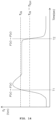
- Equation 4 shows an embodiment of a method for the controller to change the control mode of the SEA between the torque control and the position control based on a result of the comparison between the external torque ( ⁇ l ) and the critical torque ( ⁇ th ) at step S930.
- P s K P ⁇ r ⁇ ⁇ m + K D s ⁇ r ⁇ ⁇ m
- the controller may switch the control mode of the SEA to the position control.
- the controller may switch the control mode of the SEA to the torque control.
- the driving motor may generate torque having an opposite direction until the external torque ( ⁇ l ) reaches a critical torque ( ⁇ th ), so the position control is maintained.
- the position control may switch to the torque control.
- the torque control may switch to the position control, so the load 1000 returns to the original position by the rotation of the driving motor.
- the driving motor may continue to rotate the load 1000 until the external torque ( ⁇ l ) reaches the critical torque ( ⁇ th ), so the position control is maintained.
- the position control may switch to the torque control.
- the position control switches to the torque control at a point of time (t1) at which the external torque ( ⁇ l ) increases and exceeds the critical torque ( ⁇ th ). After the control mode switches to the torque control, torque ( ⁇ l ) may be reduced.
Landscapes
- Engineering & Computer Science (AREA)
- Robotics (AREA)
- Mechanical Engineering (AREA)
- Power Engineering (AREA)
- Human Computer Interaction (AREA)
- Microelectronics & Electronic Packaging (AREA)
- Physics & Mathematics (AREA)
- Electromagnetism (AREA)
- Connection Of Motors, Electrical Generators, Mechanical Devices, And The Like (AREA)
- Control Of Electric Motors In General (AREA)
- Manipulator (AREA)
Claims (3)
- Verfahren zum Steuern eines serienelastischen Aktuators (SEA), der aufweist: eine motorseitige Rotationseinheit (100) und eine lastseitige Rotationseinheit (200), die gekoppelt sind, um eine Rotationskraft eines Antriebsmotors auf eine Last zu übertragen, und elastische Elemente (300) und einen Sensorteil, der einen Magnetkörper (400) und einen Hallsensor (410) aufweist, wobei das Verfahren aufweist:Messen einer relativen Verschiebung zwischen der motorseitigen Rotationseinheit und der lastseitigen Rotationseinheit,Berechnen eines externen Drehmoments durch eine externe Kraft, die auf die Lastseite ausgeübt wird, basierend auf der gemessenen Verschiebung und der Härte (K) des elastischen Elements,Vergleichen des berechneten externen Drehmoments mit einem kritischen Drehmoment (τth) undUmschalten eines Steuermodus des SEA auf irgendeines einer Drehmomentsteuerung und einer Positionssteuerung basierend auf einem Ergebnis des Vergleichs,wobei, wenn das externe Drehmoment auf einen Wert ansteigt, der größer als das kritische Drehmoment (τth) ist, der Steuermodus von der Positionssteuerung zur Drehmomentsteuerung umschaltet, undwenn das externe Drehmoment auf einen Wert(τth-τhys), der durch Subtrahieren des gegebenen Drehmoments (τhys) vom kritischen Drehmoment (τth) erhalten wird, oder weniger abfällt, der Steuermodus von der Drehmomentsteuerung zur Positionssteuerung umschaltet,wobei ein Außenrahmen, der Aufnahmeräume aufweist, an denen das Paar elastischer Elemente befestigt ist, in irgendeiner von der motorseitigen Rotationseinheit und der lastseitigen Rotationseinheit ausgebildet ist,wobei ein Innenrahmen zum Abstützen des Paares elastischer Elemente darin in einer anderen von der motorseitigen Rotationseinheit und der lastseitigen Rotationseinheit ausgebildet ist,wobei die Verschiebung mittels des Magnetkörpers und des Hallsensors gemessen wird, die jeweils an korrespondierenden Positionen der motorseitigen Rotationseinheit und der lastseitigen Rotationseinheit positioniert sind, undwobei der Magnetkörper zwischen den beiden zueinander benachbarten Innenrahmen positioniert ist und der Hallsensor an dem Außenrahmen positioniert ist.
- Verfahren gemäß Anspruch 1, wobei mindestens ein Paar der elastischen Elemente in Räumen zwischen der motorseitigen Rotationseinheit und der lastseitigen Rotationseinheit bereitgestellt ist.
- Serienelastischer Aktuator, aufweisend:eine motorseitige Rotationseinheit (100), die mit einem Antriebsmotor gekoppelt ist und durch eine Rotationskraft des Antriebsmotors gedreht wird,eine lastseitige Rotationseinheit (200), die mit der motorseitigen Rotationseinheit gekoppelt ist, um die Rotationskraft des Antriebsmotors auf eine Last zu übertragen,mindestens ein Paar elastischer Elemente (300), die in Räumen zwischen der motorseitigen Rotationseinheit und der lastseitigen Rotationseinheit bereitgestellt sind,einen Sensorteil, der konfiguriert ist, um eine relative Verschiebung zwischen der motorseitigen Rotationseinheit und der lastseitigen Rotationseinheit zu messen, undeine Steuereinrichtung, die konfiguriert ist, um ein externes Drehmoment durch eine externe Kraft, die auf die Lastseite ausgeübt wird, mittels der gemessenen Verschiebung zu berechnen und einen Steuermodus auf irgendeines von einer Drehmomentsteuerung und einer Positionssteuerung basierend auf einem Ergebnis eines Vergleichs zwischen dem berechneten externen Drehmoment und einem kritischen Drehmoment umzuschalten,wobei ein Außenrahmen, der Aufnahmeräume aufweist, an denen das Paar elastischer Elemente befestigt ist, in irgendeiner der motorseitigen Rotationseinheit und der lastseitigen Rotationseinheit ausgebildet ist,wobei ein Innenrahmen zum Abstützen des Paares elastischer Elemente darin in einer anderen von der motorseitigen Rotationseinheit und der lastseitigen Rotationseinheit ausgebildet ist,wobei der Sensorteil einen Magnetkörper (400) und einen Hallsensor (410) aufweist, die jeweils an korrespondierenden Positionen der motorseitigen Rotationseinheit und der lastseitigen Rotationseinheit positioniert sind, undder Magnetkörper zwischen den beiden zueinander benachbarten Innenrahmen positioniert ist und der Hallsensor an dem Außenrahmen positioniert ist.
Applications Claiming Priority (3)
| Application Number | Priority Date | Filing Date | Title |
|---|---|---|---|
| KR1020170037706A KR101901167B1 (ko) | 2017-03-24 | 2017-03-24 | 직렬 탄성 액추에이터 장치 |
| KR1020170056191A KR101901168B1 (ko) | 2017-05-02 | 2017-05-02 | 직렬 탄성 액추에이터 제어 방법 및 그를 이용한 시스템 |
| PCT/KR2018/002564 WO2018174428A1 (ko) | 2017-03-24 | 2018-03-05 | 직렬 탄성 액추에이터 장치, 직렬 탄성 액추에이터 제어 방법 및 그를 이용한 시스템 |
Publications (3)
| Publication Number | Publication Date |
|---|---|
| EP3603901A1 EP3603901A1 (de) | 2020-02-05 |
| EP3603901A4 EP3603901A4 (de) | 2020-04-15 |
| EP3603901B1 true EP3603901B1 (de) | 2025-05-07 |
Family
ID=63585501
Family Applications (1)
| Application Number | Title | Priority Date | Filing Date |
|---|---|---|---|
| EP18759230.8A Active EP3603901B1 (de) | 2017-03-24 | 2018-03-05 | Serienelastisches stellglied , steuerungsverfahren für serienelastisches stellglied und system mit verwendung davon |
Country Status (5)
| Country | Link |
|---|---|
| US (1) | US11431222B2 (de) |
| EP (1) | EP3603901B1 (de) |
| JP (1) | JP7177698B2 (de) |
| CN (1) | CN109070344B (de) |
| WO (1) | WO2018174428A1 (de) |
Families Citing this family (7)
| Publication number | Priority date | Publication date | Assignee | Title |
|---|---|---|---|---|
| WO2019164037A1 (ko) * | 2018-02-23 | 2019-08-29 | (주)로보티즈 | 연성부를 갖는 액추에이터 모듈 |
| CN110480675B (zh) * | 2019-08-28 | 2021-03-30 | 王光远 | 一种压电式变刚度弹性关节 |
| CN110815254B (zh) * | 2019-12-06 | 2025-03-14 | 深圳优艾智合机器人科技有限公司 | 一种柔性结构、柔性连接件、执行机构、机械臂及机器人 |
| JP7721895B2 (ja) * | 2021-01-15 | 2025-08-13 | オムロン株式会社 | 駆動システム、制御方法および制御プログラム |
| JP7624850B2 (ja) * | 2021-03-05 | 2025-01-31 | 住友重機械工業株式会社 | ロボットアームの制御装置、制御方法、システム、及びプログラム |
| JP2023059235A (ja) * | 2021-10-14 | 2023-04-26 | ヤンマーホールディングス株式会社 | 駆動装置及び作業機械 |
| US12459793B2 (en) * | 2022-11-14 | 2025-11-04 | Hornet Acquisitionco, Llc | Method to detect homing loads in rescue hoist and winch assemblies |
Citations (3)
| Publication number | Priority date | Publication date | Assignee | Title |
|---|---|---|---|---|
| GB2235067A (en) * | 1989-05-25 | 1991-02-20 | Toyoda Chuo Kenkyusho Kk | Co-ordinated position and force control for a manipulator |
| US6294890B1 (en) * | 1998-07-23 | 2001-09-25 | Seiko Instruments Inc. | Robot controller |
| US20090069942A1 (en) * | 2007-09-11 | 2009-03-12 | Taro Takahashi | Robot apparatus and method of controlling the same |
Family Cites Families (17)
| Publication number | Priority date | Publication date | Assignee | Title |
|---|---|---|---|---|
| JPS58177253U (ja) * | 1982-05-22 | 1983-11-26 | 東芝機械株式会社 | 送りユニツト |
| JPH07197941A (ja) * | 1993-12-30 | 1995-08-01 | Sanshin Ind Co Ltd | シャフトカップリング |
| US5650704A (en) * | 1995-06-29 | 1997-07-22 | Massachusetts Institute Of Technology | Elastic actuator for precise force control |
| JP2002059388A (ja) * | 2000-08-23 | 2002-02-26 | Sony Corp | 回転型アクチュエータおよび回転型アクチュエータを有する歩行ロボット |
| JP2002242950A (ja) * | 2000-12-12 | 2002-08-28 | Asa Denshi Kogyo Kk | 軸継手 |
| JP3961892B2 (ja) * | 2002-06-21 | 2007-08-22 | 株式会社アドバネクス | ロボット装置および緩衝装置 |
| JP2005319922A (ja) * | 2004-05-10 | 2005-11-17 | Koyo Seiko Co Ltd | 電動パワーステアリング装置 |
| GB2440753A (en) * | 2006-08-04 | 2008-02-13 | Univ Sussex | Force sensor and programmable spring emulator |
| JP2011083884A (ja) * | 2009-10-19 | 2011-04-28 | Yaskawa Electric Corp | 可変剛性機構及びロボット |
| US8525460B2 (en) | 2010-02-02 | 2013-09-03 | GM Global Technology Operations LLC | Architecture for robust force and impedance control of series elastic actuators |
| JP5483466B2 (ja) * | 2011-04-15 | 2014-05-07 | アサ電子工業株式会社 | カップリング |
| JP5907678B2 (ja) * | 2011-07-20 | 2016-04-26 | オリンパス株式会社 | 医療用動作機構およびマニピュレータ |
| US9079305B2 (en) * | 2012-08-28 | 2015-07-14 | Rethink Robotics, Inc. | Monitoring robot sensor consistency |
| CN103624797B (zh) * | 2013-12-16 | 2015-07-08 | 哈尔滨工业大学 | 一种旋转式可调刚度串联弹性机器人关节 |
| KR20150073791A (ko) * | 2013-12-23 | 2015-07-01 | 현대자동차주식회사 | 로봇용 안전관절장치 |
| CN105397808B (zh) * | 2015-12-15 | 2017-03-22 | 南开大学 | 基于压簧的线性串联弹性驱动器 |
| JP2016129488A (ja) * | 2016-03-30 | 2016-07-14 | アスモ株式会社 | 回転伝達装置及びモータ |
-
2018
- 2018-03-05 WO PCT/KR2018/002564 patent/WO2018174428A1/ko not_active Ceased
- 2018-03-05 CN CN201880000684.1A patent/CN109070344B/zh active Active
- 2018-03-05 JP JP2018532271A patent/JP7177698B2/ja active Active
- 2018-03-05 US US16/063,957 patent/US11431222B2/en active Active
- 2018-03-05 EP EP18759230.8A patent/EP3603901B1/de active Active
Patent Citations (3)
| Publication number | Priority date | Publication date | Assignee | Title |
|---|---|---|---|---|
| GB2235067A (en) * | 1989-05-25 | 1991-02-20 | Toyoda Chuo Kenkyusho Kk | Co-ordinated position and force control for a manipulator |
| US6294890B1 (en) * | 1998-07-23 | 2001-09-25 | Seiko Instruments Inc. | Robot controller |
| US20090069942A1 (en) * | 2007-09-11 | 2009-03-12 | Taro Takahashi | Robot apparatus and method of controlling the same |
Also Published As
| Publication number | Publication date |
|---|---|
| JP7177698B2 (ja) | 2022-11-24 |
| JP2020511910A (ja) | 2020-04-16 |
| US20210013773A1 (en) | 2021-01-14 |
| EP3603901A4 (de) | 2020-04-15 |
| EP3603901A1 (de) | 2020-02-05 |
| CN109070344B (zh) | 2023-04-04 |
| WO2018174428A1 (ko) | 2018-09-27 |
| US11431222B2 (en) | 2022-08-30 |
| CN109070344A (zh) | 2018-12-21 |
Similar Documents
| Publication | Publication Date | Title |
|---|---|---|
| EP3603901B1 (de) | Serienelastisches stellglied , steuerungsverfahren für serienelastisches stellglied und system mit verwendung davon | |
| US8874263B2 (en) | Walking robot and control method thereof | |
| EP3956112B1 (de) | Verfahren zur steuerung eines roboterarms auf der basis adaptiver reibung | |
| US6956346B2 (en) | Robot apparatus, and load absorbing apparatus and method | |
| US8661929B2 (en) | Device for generating stiffness and method for controlling stiffness and joint of robot manipulator comprising the same | |
| JP2770982B2 (ja) | マニピユレータの位置と力の協調制御装置 | |
| EP3124183B1 (de) | Roboter, steuerungsvorrichtung und robotersystem | |
| Focchi et al. | Torque-control based compliant actuation of a quadruped robot | |
| US11491666B2 (en) | Control system, control method, and control program | |
| US6989645B2 (en) | Robot apparatus, and load absorbing apparatus and method | |
| JP5467291B2 (ja) | 省エネルギー型ロボット関節駆動制御システム | |
| Suzuki et al. | Single-inertialization based on high-backdrivability control using equivalent disturbance compensator for human interaction robot | |
| Kashiri et al. | Dynamic modeling and adaptable control of the CompAct™ arm | |
| KR101901167B1 (ko) | 직렬 탄성 액추에이터 장치 | |
| Choi et al. | Development of the Cartesian arm exoskeleton system (CAES) using a 3-axis force/torque sensor | |
| KR20180122301A (ko) | 직렬 탄성 액추에이터 제어 방법 및 그를 이용한 시스템 | |
| JP4442464B2 (ja) | 多関節アーム機構 | |
| KR101901168B1 (ko) | 직렬 탄성 액추에이터 제어 방법 및 그를 이용한 시스템 | |
| Ishizaki et al. | Mechanics and structure for mobile power-assist equipment | |
| Kuroki et al. | Three-dimensional Motion Mechanism with Tendon-Driven Gravity Compensation | |
| JP2024120660A (ja) | アクチュエータ及びアクチュエータの制御方法 | |
| CN121568817A (zh) | 机器人的控制 | |
| Eltimsahy et al. | Near-minimum time control of flexible manipulators with a payload | |
| Meer et al. | Cooperative manipulation of flexible objects: Initial experiments. |
Legal Events
| Date | Code | Title | Description |
|---|---|---|---|
| STAA | Information on the status of an ep patent application or granted ep patent |
Free format text: STATUS: UNKNOWN |
|
| STAA | Information on the status of an ep patent application or granted ep patent |
Free format text: STATUS: THE INTERNATIONAL PUBLICATION HAS BEEN MADE |
|
| PUAI | Public reference made under article 153(3) epc to a published international application that has entered the european phase |
Free format text: ORIGINAL CODE: 0009012 |
|
| STAA | Information on the status of an ep patent application or granted ep patent |
Free format text: STATUS: REQUEST FOR EXAMINATION WAS MADE |
|
| 17P | Request for examination filed |
Effective date: 20180906 |
|
| AK | Designated contracting states |
Kind code of ref document: A1 Designated state(s): AL AT BE BG CH CY CZ DE DK EE ES FI FR GB GR HR HU IE IS IT LI LT LU LV MC MK MT NL NO PL PT RO RS SE SI SK SM TR |
|
| AX | Request for extension of the european patent |
Extension state: BA ME |
|
| A4 | Supplementary search report drawn up and despatched |
Effective date: 20200317 |
|
| RIC1 | Information provided on ipc code assigned before grant |
Ipc: B25J 19/00 20060101ALI20200311BHEP Ipc: B25J 13/08 20060101ALI20200311BHEP Ipc: H02K 7/00 20060101ALI20200311BHEP Ipc: H02K 11/215 20160101ALI20200311BHEP Ipc: B25J 9/12 20060101AFI20200311BHEP Ipc: B25J 9/00 20060101ALI20200311BHEP Ipc: B25J 9/16 20060101ALI20200311BHEP Ipc: B25J 19/02 20060101ALI20200311BHEP |
|
| DAV | Request for validation of the european patent (deleted) | ||
| DAX | Request for extension of the european patent (deleted) | ||
| STAA | Information on the status of an ep patent application or granted ep patent |
Free format text: STATUS: EXAMINATION IS IN PROGRESS |
|
| 17Q | First examination report despatched |
Effective date: 20220704 |
|
| GRAP | Despatch of communication of intention to grant a patent |
Free format text: ORIGINAL CODE: EPIDOSNIGR1 |
|
| STAA | Information on the status of an ep patent application or granted ep patent |
Free format text: STATUS: GRANT OF PATENT IS INTENDED |
|
| INTG | Intention to grant announced |
Effective date: 20241128 |
|
| GRAS | Grant fee paid |
Free format text: ORIGINAL CODE: EPIDOSNIGR3 |
|
| GRAA | (expected) grant |
Free format text: ORIGINAL CODE: 0009210 |
|
| STAA | Information on the status of an ep patent application or granted ep patent |
Free format text: STATUS: THE PATENT HAS BEEN GRANTED |
|
| AK | Designated contracting states |
Kind code of ref document: B1 Designated state(s): AL AT BE BG CH CY CZ DE DK EE ES FI FR GB GR HR HU IE IS IT LI LT LU LV MC MK MT NL NO PL PT RO RS SE SI SK SM TR |
|
| REG | Reference to a national code |
Ref country code: GB Ref legal event code: FG4D |
|
| REG | Reference to a national code |
Ref country code: CH Ref legal event code: EP |
|
| REG | Reference to a national code |
Ref country code: DE Ref legal event code: R096 Ref document number: 602018081729 Country of ref document: DE |
|
| REG | Reference to a national code |
Ref country code: IE Ref legal event code: FG4D |
|
| REG | Reference to a national code |
Ref country code: NL Ref legal event code: MP Effective date: 20250507 |
|
| PG25 | Lapsed in a contracting state [announced via postgrant information from national office to epo] |
Ref country code: PT Free format text: LAPSE BECAUSE OF FAILURE TO SUBMIT A TRANSLATION OF THE DESCRIPTION OR TO PAY THE FEE WITHIN THE PRESCRIBED TIME-LIMIT Effective date: 20250908 Ref country code: ES Free format text: LAPSE BECAUSE OF FAILURE TO SUBMIT A TRANSLATION OF THE DESCRIPTION OR TO PAY THE FEE WITHIN THE PRESCRIBED TIME-LIMIT Effective date: 20250507 Ref country code: FI Free format text: LAPSE BECAUSE OF FAILURE TO SUBMIT A TRANSLATION OF THE DESCRIPTION OR TO PAY THE FEE WITHIN THE PRESCRIBED TIME-LIMIT Effective date: 20250507 |
|
| REG | Reference to a national code |
Ref country code: LT Ref legal event code: MG9D |
|
| PG25 | Lapsed in a contracting state [announced via postgrant information from national office to epo] |
Ref country code: GR Free format text: LAPSE BECAUSE OF FAILURE TO SUBMIT A TRANSLATION OF THE DESCRIPTION OR TO PAY THE FEE WITHIN THE PRESCRIBED TIME-LIMIT Effective date: 20250808 Ref country code: NO Free format text: LAPSE BECAUSE OF FAILURE TO SUBMIT A TRANSLATION OF THE DESCRIPTION OR TO PAY THE FEE WITHIN THE PRESCRIBED TIME-LIMIT Effective date: 20250807 |
|
| PG25 | Lapsed in a contracting state [announced via postgrant information from national office to epo] |
Ref country code: NL Free format text: LAPSE BECAUSE OF FAILURE TO SUBMIT A TRANSLATION OF THE DESCRIPTION OR TO PAY THE FEE WITHIN THE PRESCRIBED TIME-LIMIT Effective date: 20250507 Ref country code: PL Free format text: LAPSE BECAUSE OF FAILURE TO SUBMIT A TRANSLATION OF THE DESCRIPTION OR TO PAY THE FEE WITHIN THE PRESCRIBED TIME-LIMIT Effective date: 20250507 |
|
| REG | Reference to a national code |
Ref country code: AT Ref legal event code: MK05 Ref document number: 1791973 Country of ref document: AT Kind code of ref document: T Effective date: 20250507 |
|
| PG25 | Lapsed in a contracting state [announced via postgrant information from national office to epo] |
Ref country code: BG Free format text: LAPSE BECAUSE OF FAILURE TO SUBMIT A TRANSLATION OF THE DESCRIPTION OR TO PAY THE FEE WITHIN THE PRESCRIBED TIME-LIMIT Effective date: 20250507 |
|
| PG25 | Lapsed in a contracting state [announced via postgrant information from national office to epo] |
Ref country code: HR Free format text: LAPSE BECAUSE OF FAILURE TO SUBMIT A TRANSLATION OF THE DESCRIPTION OR TO PAY THE FEE WITHIN THE PRESCRIBED TIME-LIMIT Effective date: 20250507 |
|
| PG25 | Lapsed in a contracting state [announced via postgrant information from national office to epo] |
Ref country code: AT Free format text: LAPSE BECAUSE OF FAILURE TO SUBMIT A TRANSLATION OF THE DESCRIPTION OR TO PAY THE FEE WITHIN THE PRESCRIBED TIME-LIMIT Effective date: 20250507 |
|
| PG25 | Lapsed in a contracting state [announced via postgrant information from national office to epo] |
Ref country code: RS Free format text: LAPSE BECAUSE OF FAILURE TO SUBMIT A TRANSLATION OF THE DESCRIPTION OR TO PAY THE FEE WITHIN THE PRESCRIBED TIME-LIMIT Effective date: 20250807 |
|
| PG25 | Lapsed in a contracting state [announced via postgrant information from national office to epo] |
Ref country code: IS Free format text: LAPSE BECAUSE OF FAILURE TO SUBMIT A TRANSLATION OF THE DESCRIPTION OR TO PAY THE FEE WITHIN THE PRESCRIBED TIME-LIMIT Effective date: 20250907 |
|
| PG25 | Lapsed in a contracting state [announced via postgrant information from national office to epo] |
Ref country code: LV Free format text: LAPSE BECAUSE OF FAILURE TO SUBMIT A TRANSLATION OF THE DESCRIPTION OR TO PAY THE FEE WITHIN THE PRESCRIBED TIME-LIMIT Effective date: 20250507 |
|
| PG25 | Lapsed in a contracting state [announced via postgrant information from national office to epo] |
Ref country code: DK Free format text: LAPSE BECAUSE OF FAILURE TO SUBMIT A TRANSLATION OF THE DESCRIPTION OR TO PAY THE FEE WITHIN THE PRESCRIBED TIME-LIMIT Effective date: 20250507 Ref country code: SM Free format text: LAPSE BECAUSE OF FAILURE TO SUBMIT A TRANSLATION OF THE DESCRIPTION OR TO PAY THE FEE WITHIN THE PRESCRIBED TIME-LIMIT Effective date: 20250507 |
|
| PG25 | Lapsed in a contracting state [announced via postgrant information from national office to epo] |
Ref country code: CZ Free format text: LAPSE BECAUSE OF FAILURE TO SUBMIT A TRANSLATION OF THE DESCRIPTION OR TO PAY THE FEE WITHIN THE PRESCRIBED TIME-LIMIT Effective date: 20250507 |
|
| PG25 | Lapsed in a contracting state [announced via postgrant information from national office to epo] |
Ref country code: EE Free format text: LAPSE BECAUSE OF FAILURE TO SUBMIT A TRANSLATION OF THE DESCRIPTION OR TO PAY THE FEE WITHIN THE PRESCRIBED TIME-LIMIT Effective date: 20250507 |
|
| PG25 | Lapsed in a contracting state [announced via postgrant information from national office to epo] |
Ref country code: RO Free format text: LAPSE BECAUSE OF FAILURE TO SUBMIT A TRANSLATION OF THE DESCRIPTION OR TO PAY THE FEE WITHIN THE PRESCRIBED TIME-LIMIT Effective date: 20250507 Ref country code: SK Free format text: LAPSE BECAUSE OF FAILURE TO SUBMIT A TRANSLATION OF THE DESCRIPTION OR TO PAY THE FEE WITHIN THE PRESCRIBED TIME-LIMIT Effective date: 20250507 |
|
| REG | Reference to a national code |
Ref country code: DE Ref legal event code: R097 Ref document number: 602018081729 Country of ref document: DE |
|
| PLBE | No opposition filed within time limit |
Free format text: ORIGINAL CODE: 0009261 |
|
| STAA | Information on the status of an ep patent application or granted ep patent |
Free format text: STATUS: NO OPPOSITION FILED WITHIN TIME LIMIT |
|
| REG | Reference to a national code |
Ref country code: CH Ref legal event code: L10 Free format text: ST27 STATUS EVENT CODE: U-0-0-L10-L00 (AS PROVIDED BY THE NATIONAL OFFICE) Effective date: 20260318 |