EP3601025B1 - Vorbereitungsgestell für fahrzeugmontage und verfahren zur montage eines fahrzeugs - Google Patents
Vorbereitungsgestell für fahrzeugmontage und verfahren zur montage eines fahrzeugs Download PDFInfo
- Publication number
- EP3601025B1 EP3601025B1 EP18713306.1A EP18713306A EP3601025B1 EP 3601025 B1 EP3601025 B1 EP 3601025B1 EP 18713306 A EP18713306 A EP 18713306A EP 3601025 B1 EP3601025 B1 EP 3601025B1
- Authority
- EP
- European Patent Office
- Prior art keywords
- guide device
- vehicle
- sled
- preparation
- housing
- Prior art date
- Legal status (The legal status is an assumption and is not a legal conclusion. Google has not performed a legal analysis and makes no representation as to the accuracy of the status listed.)
- Active
Links
- 238000002360 preparation method Methods 0.000 title claims description 43
- 238000000034 method Methods 0.000 title claims description 27
- 230000001681 protective effect Effects 0.000 claims description 13
- 238000003032 molecular docking Methods 0.000 claims description 7
- 230000000295 complement effect Effects 0.000 claims description 4
- 230000003247 decreasing effect Effects 0.000 claims description 3
- 210000000056 organ Anatomy 0.000 description 4
- 230000010485 coping Effects 0.000 description 2
- 238000004519 manufacturing process Methods 0.000 description 2
- 230000004224 protection Effects 0.000 description 2
- 238000002485 combustion reaction Methods 0.000 description 1
- 239000006185 dispersion Substances 0.000 description 1
- 239000012530 fluid Substances 0.000 description 1
- 238000007789 sealing Methods 0.000 description 1
- 238000007493 shaping process Methods 0.000 description 1
- 230000001360 synchronised effect Effects 0.000 description 1
Images

Classifications
-
- B—PERFORMING OPERATIONS; TRANSPORTING
- B62—LAND VEHICLES FOR TRAVELLING OTHERWISE THAN ON RAILS
- B62D—MOTOR VEHICLES; TRAILERS
- B62D65/00—Designing, manufacturing, e.g. assembling, facilitating disassembly, or structurally modifying motor vehicles or trailers, not otherwise provided for
- B62D65/02—Joining sub-units or components to, or positioning sub-units or components with respect to, body shell or other sub-units or components
- B62D65/024—Positioning of sub-units or components with respect to body shell or other sub-units or components
- B62D65/026—Positioning of sub-units or components with respect to body shell or other sub-units or components by using a jig or the like; Positioning of the jig
-
- B—PERFORMING OPERATIONS; TRANSPORTING
- B62—LAND VEHICLES FOR TRAVELLING OTHERWISE THAN ON RAILS
- B62D—MOTOR VEHICLES; TRAILERS
- B62D65/00—Designing, manufacturing, e.g. assembling, facilitating disassembly, or structurally modifying motor vehicles or trailers, not otherwise provided for
- B62D65/02—Joining sub-units or components to, or positioning sub-units or components with respect to, body shell or other sub-units or components
- B62D65/10—Joining sub-units or components to, or positioning sub-units or components with respect to, body shell or other sub-units or components the sub-units or components being engines, clutches or transmissions
-
- B—PERFORMING OPERATIONS; TRANSPORTING
- B60—VEHICLES IN GENERAL
- B60K—ARRANGEMENT OR MOUNTING OF PROPULSION UNITS OR OF TRANSMISSIONS IN VEHICLES; ARRANGEMENT OR MOUNTING OF PLURAL DIVERSE PRIME-MOVERS IN VEHICLES; AUXILIARY DRIVES FOR VEHICLES; INSTRUMENTATION OR DASHBOARDS FOR VEHICLES; ARRANGEMENTS IN CONNECTION WITH COOLING, AIR INTAKE, GAS EXHAUST OR FUEL SUPPLY OF PROPULSION UNITS IN VEHICLES
- B60K20/00—Arrangement or mounting of change-speed gearing control devices in vehicles
- B60K20/02—Arrangement or mounting of change-speed gearing control devices in vehicles of initiating means
- B60K20/04—Arrangement or mounting of change-speed gearing control devices in vehicles of initiating means floor mounted
Definitions
- the invention relates to a device and a method for assembling a vehicle, in particular a preparation sled.
- the present invention relates to a device and method for assembling an electrical harness in a vehicle, in particular a motor vehicle.
- a set of vehicle components is prepared, comprising for example a thermal traction with its exhaust line and its thermal protections, an electric traction motor and its battery, the gearbox fixed to the thermal engine and gearbox control cables fixed to the gearbox, a set of electrical harnesses.
- This set of vehicle components is pre-positioned or indexed on a support forming a preparation sled.
- each member is positioned relative to the other members, in an assembly position corresponding to final fixing positions, for example provided on the bodywork .
- This sledge is then transported from the "POM” station to the main assembly line, to be “capped” by the vehicle body.
- styling will be understood to mean the assembly operation on the main assembly line consisting of aligning the body of the vehicle with this preparation sled, then docking the body of the vehicle on this assembly of vehicle components, by a relative vertical movement, generally a downward movement of the bodywork, so as to reach a position allowing the assembly of these members on the bodywork of the vehicle.
- gearbox control cables usually two cables
- gear lever located inside the interior of the vehicle
- electrical harnesses to electrical outlets inside the interior of the vehicle.
- passenger compartment will be understood throughout the text of this document to mean the volume internal to the bodywork, access to which requires the passage of an operator or a manipulator through a location in the bodywork reserved for an opening.
- control cables or the electrical harnesses connect a component of the assembly prepared at the "POM" station to a part of the body delivered to the main assembly line.
- the gear control cables On the main assembly line, during the assembly stage following "coping", the gear control cables, already attached to the gearbox, as well as the electrical harnesses, arrive from below the body of the vehicle so that their free end is connected respectively to the gear lever and to the electrical sockets.
- the speed control cables and electrical harnesses pass through an opening in the part of the lower body generally called the tunnel. When passing through this opening during "styling", there is a risk of snagging and damaging the cables of the speed control or the electrical harnesses.
- the patent EP-B-2 134 590 discloses an assembly method as previously briefly described, using a guide device provided on the sled to guide the cables of the gearbox control through the opening during the "styling" operation.
- the free ends of the cables are collected inside the passenger compartment, after having removed the guide device, in order to connect them to the gear lever.
- Fixing all of the vehicle components to the bodywork on the main assembly line then comprises an operation of positioning a moving part for closing and sealing the opening of the bodywork.
- This moving part must be brought by the operator, precisely to the location of the opening, while he must have his hands free to recover the free ends of the cables and connect them to the gear lever, which represents a loss of time.
- the ergonomics of this operation of positioning the moving part is degraded, the operator being able to hold on only with one hand and risking losing the closure element.
- the object of the present invention is to remedy these problems.
- the subject of the invention is a preparation sled for assembling a vehicle, said preparation sled comprising a support, a set of mechanical components to be assembled indexed on said support, and a moving part to be assembled , this preparation toboggan further comprising a device for guiding an elongated flexible member of the set of mechanical members, this guiding device being a protective casing having a base indexed with respect to the support and a free end opposite open section, the guide device comprising a housing open towards the free end and of complementary shape to the moving part.
- this housing allows the guide device to house the moving part, an assembly operator having access to this moving part through the opening of the housing.
- the operator keeps his hands free and, after a "styling" operation, can recover this part from the passenger compartment of the vehicle, without having to bring it by his own means, which saves time and to improve the ergonomics of its assembly operation.
- the housing comprises grooves partially encircling the contour of the moving part.
- these grooves are simple means of making the housing, and make it possible to hold the moving part while allowing easy sliding of the moving part, both to slide it into the housing, but also to remove it when the operator must mount it.
- the housing is elongated, the elongated shape defining an axis orthogonal to the open section.
- this arrangement makes it possible to house a flat mobile part whose largest section is larger than the open section.
- the grooves have a width less than the thickness of the contour of the mobile part and have elastic lips.
- the moving part is pinched in the housing, which prevents it from escaping when the preparation sled moves.
- the protective casing surrounding the elongated flexible member and defining an interior volume, the protective casing also having a decreasing cross-section from the indexed base to the free end, the housing is in the interior volume .
- This feature allows the guide device to protect the moving part during the "styling" operation, so that it does not catch in an opening in the body through which the guide device passes.
- the moving part is transported by the guide device, and therefore by the preparation sled, from the "POM" station to the passenger compartment of the vehicle, the passenger compartment being advantageously the place where this moving part must be mounted.
- the operator has his hands free to recover the free end of the elongate flexible member in the passenger compartment and remove the guide device, which represents a saving of time.
- the ergonomics of this operation for positioning the moving part is improved, the operator being able to hold on with both hands and not risk losing the closure element.
- this moving part is a moving part for closing the opening of the bodywork, precisely because the guide device provides the moving part exactly at the place of its mounting, which saves the operator handling time.
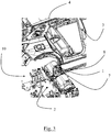
- the set represented on the figure 2 comprises a guide device 1 according to one embodiment of the invention.
- the picture 2 discloses a preparation toboggan 10 for the assembly of a vehicle comprises a support 2, in the form of a plate supporting a set of positioners for indexing in position a set of mechanical components to be assembled.
- a moving part 7 to be assembled is also present, for example a moving part 7 for closing an opening 4 of the bodywork 3 of the vehicle, this opening 4 being described by the picture 3 .
- the guide device 1 guides an elongated flexible member 8 of the set of mechanical members, for example an electrical harness.
- This elongated member 8 may very well, as a variant, be a control cable for a gearbox, a fluid pipe, or any elongated flexible member 8 forming part of the set of mechanical members to be assembled.
- the guide device 1 is a protective casing having an indexed base 11 described on the figure 1 , this base 11 being indexed with respect to the support 2.
- the indexing of the base 11 is not necessarily done directly on the support 2. Indeed, the base 11 can be indexed on one of the members of the set of mechanical members, for example a protective screen, which itself is indexed to medium 2.
- the guide device 1 comprises a free end 6 opposite the base 11, the opposite free end 6 being of open section.
- the guide device further comprises a housing 5 open towards the opposite free end 6 and of complementary shape to the moving part 7.
- the moving part 7 is flat, and the housing 5 comprises grooves 12 partially encircling the contour of the moving part 7.
- the housing 5 is elongated, this elongated shape defining an axis orthogonal to the open section.
- the grooves 12, two in number have a width less than the thickness of the contour of the moving part 7 and have elastic lips.
- the set represented on the figure 1 comprises the guide device 1 according to one embodiment of the invention.
- Y are represented the indexed base 11, the housing 5, the grooves 12, and the opposite free end 6 giving the open section.
- the movable part 7 slides in the grooves 12 and comes into abutment against two stops 22, these stops forming part, with the grooves 12, of the shape complementary to the said movable part 7.
- the guide device is a lightened protective box, having side openings, but in variants this box can be made without side openings.
- the figure 1 also shows an indexing system 20, 21 of the guide device 1, comprising two centering pins 20 and a support 21, the guide device 1 being removably indexed relative to the support 2 of the preparation sled 10 previously described .
- the protective casing defines an interior volume, and has a decreasing cross-section from its indexed base 11 to the free end 6.
- the housing 5 is in the interior volume.
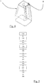
- the figure 5 illustrates a flowchart according to an assembly method of the invention.
- This assembly method uses the preparation sled 10 and an assembly line docking the bodywork 3 of the vehicle on the preparation sled 10, thus carrying out the "styling" operation.
- This method comprises a first step 110 of positioning the mechanical components on the support 2 of the preparation sled 10, in particular the mechanical components of a traction chain.
- This step corresponding to the so-called "POM” station, is generally carried out by an operator and/or by a manipulator, and consists in positioning the mechanical components on the positioners of the support 2.
- the heaviest components such as the combustion engine and the gearbox, they are coupled by means of suitable tools.
- This method comprises a second step 120 of indexing the guide device 1 with respect to the support 2, while conforming the elongated flexible element 8 by the guide device 1.
- This indexing of the guide device consists in making the system of indexing 20, 21 of the guide device 1 with corresponding positioners of the support 2.
- these corresponding positioners are made by mechanical members, for example holes made in a thermal protection on which the guide device is placed.
- Another example would consist of integrating these positioners on a beam fixing clip.
- the guide device 1 remains removable, that is to say it can be removed without having to dismantle a binding.
- This guide device 1 once indexed, conforms the elongated flexible element 8.
- the operator passes the elongated flexible element 8 through the protective casing which then surrounds the elongated flexible element 8, giving it an inflection making it possible to orient the elongated flexible element 8 so that it corresponds to the opening 4 of the bodywork 3 during the "styling" operation.
- This method includes a third step 130 bringing the preparation sled 10 to the assembly line.
- This step can be carried out by a conveyor, in an automated way.
- the preparation sled 10 is then synchronized with the assembly line.
- This method comprises a fourth step 140 of "capping" which docks the bodywork 3 of the vehicle on the preparation sled 10, the guide device 1 passing through the opening 4 of the bodywork 3.
- This docking is achieved by a relative vertical movement, generally a downward movement of the bodywork, so as to reach a position allowing the assembly of these members on the bodywork of the vehicle, and in particular to pass the elongated flexible element 8 through the opening 4 of the bodywork 3 without risking to attach the elongated flexible element 8 to the bodywork 3.
- This method comprises a fifth step 150 where the operator removes the guide device 1 from the support 2 through the interior of the bodywork 3, the guide device 1 being placed inside the bodywork 3. Indeed, at this step the guide device 1 has passed through the opening 4, and is only accessible from the passenger compartment of the vehicle. The elongated flexible element 8 is still inside the protective casing, and therefore passed through the opening 4 of the bodywork 3. The operator then withdraws the guide device 1 thus releasing the elongated flexible element 8 which can be connected, for example, to an electrical outlet or a gear lever depending on its nature.
- This method comprises a sixth step 160 of assembling the mechanical components on the bodywork 3.
- the preparation sled 10 is always docked with the bodywork 3, the operator can then fix all the mechanical components to the bodywork 3, the support 2 being provided, for example, to allow access to screwdrivers or other assembly tools.
- This method comprises a seventh step 170 of removing the preparation sled 10.
- the preparation sled 10 is then empty again, all the mechanical components remaining fixed to the bodywork 3.
- This method includes an eighth step 180 of returning the guide device 1 to the preparation sled 10, to be recycled and used again.
- This method further comprises a first intermediate step 125 of introducing the moving part 7 into the housing 5 before the fourth step.
- This introduction is done manually by the operator, before the "capping" operation, for example at the "POM” station.
- This method further comprises a second intermediate step 155 of removing the moving part 7 from the housing 5 between the fourth and seventh steps.
- This step is carried out by the operator, in the passenger compartment of the vehicle. The moving part 7 is then already in the passenger compartment when the operator needs to mount it.
- This method further comprises a third intermediate step 165 of assembling the moving part 7 between the fifth and eighth steps.
- the moving part 7 is the moving part 7 for closing the opening 4 of the bodywork 3
- the guide device 1 must be removed before mounting the moving part 7, which closes the opening 4.
- this movable closing part 7 comprises a leaktight passage opening for the elongated flexible element 8.
- the picture 3 shows the body 3 of a vehicle at the start of docking on the support 2 of the preparation sledge 10 with the guide device 1 of the picture 2 .
- Y are shown the moving part 7 in the guide device 1, this guide device 1 being aligned with the opening 4 of the body 3.
- the body 3 will then descend in a vertical movement created by the assembly line, so that the guide device 1 will pass through the opening 4, taking with it the moving part 7 and the elongated flexible member 8, here a electrical harness.
- the figure 4 illustrates a guide device 1 according to the art prior to the invention.
Landscapes
- Engineering & Computer Science (AREA)
- Manufacturing & Machinery (AREA)
- Chemical & Material Sciences (AREA)
- Combustion & Propulsion (AREA)
- Transportation (AREA)
- Mechanical Engineering (AREA)
- Automobile Manufacture Line, Endless Track Vehicle, Trailer (AREA)
- Automatic Assembly (AREA)
Claims (6)
- Vorbereitungsschlitten (10) zum Zusammenbauen eines Fahrzeugs, wobei der Vorbereitungsschlitten (10) einen Träger (2), einen Satz mechanischer Komponenten, die auf dem Träger (2) indexiert zu montieren sind, und ein zu montierendes bewegliches Teil (7) umfasst, wobei der Vorbereitungsschlitten (10) ferner eine Führungsvorrichtung (1) eines flexiblen länglichen Elements (8) des Satzes mechanischer Elemente umfasst, wobei die Führungsvorrichtung (1) ein Schutzgehäuse mit einer in Bezug auf die indexierten Basis (11) ist Träger (2) und einem gegenüberliegenden freien Ende (6) mit offenem Querschnitt, dadurch gekennzeichnet, dass die Führungsvorrichtung (1) ein zum freien Ende hin offenes Gehäuse (5) mit komplementärer Form zu dem beweglichen Teil (7) umfasst.
- Vorbereitungsschlitten (10) nach Anspruch 1, wobei der bewegliche Teil (7) flach ist, dadurch gekennzeichnet, dass das Gehäuse (5) Nuten (12) aufweist, die teilweise die Kontur des beweglichen Teils (7) umschließen.
- Vorbereitungsschlitten (10) nach Anspruch 2, dadurch gekennzeichnet, dass das Gehäuse (5) eine längliche Form hat, wobei die längliche Form eine Achse orthogonal zu dem offenen Abschnitt definiert.
- Vorbereitungsschlitten (10) nach Anspruch 2 oder 3, dadurch gekennzeichnet, dass die Rillen (12) eine Breite haben, die geringer ist als die Dicke des Umrisses des beweglichen Teils (7) und elastische Lippen aufweisen.
- Vorbereitungsschlitten (10) nach einem der vorhergehenden Ansprüche, wobei das Schutzgehäuse das längliche flexible Element (8) umgibt und ein Innenvolumen definiert, wobei das Schutzgehäuse einen abnehmenden Querschnitt der indexierten Basis (11) zum freien Ende (6), dadurch gekennzeichnet, dass sich das Gehäuse (5) in dem Innenvolumen befindet.
- Verfahren zum Zusammenbauen eines Fahrzeugs unter Verwendung eines Vorbereitungsschlittens (10) nach einem der vorhergehenden Ansprüche und einer Montagelinie zum Andocken einer Karosserie (3) des Fahrzeugs an den Vorbereitungsschlitten (10), wobei das Verfahren umfasst:• einen ersten Schritt (110) des Positionierens der mechanischen Elemente auf dem Träger (2), insbesondere der mechanischen Elemente einer Zugkette,• einen zweiten Schritt (120) des Indexierens der Führungsvorrichtung (1) in Bezug auf den Träger (2), während das langgestreckte flexible Element (8) durch die Führungsvorrichtung (1) angepasst wird,• einen dritten Schritt (130), um den Vorbereitungsschlitten (10) zu dem Montageband zu bringen,• einen vierten Schritt (140) des " Abdeckens ", der die Karosserie (3) des Fahrzeugs auf dem Vorbereitungsschlitten (10) platziert, wobei die Führungsvorrichtung (1) durch eine Öffnung (4) der Karosserie (3) verläuft,• einen fünften Schritt (150), bei dem der Bediener die Führungsvorrichtung (1) von der Stütze (2) durch das Innere des Körpers (3) entfernt, wobei die Führungsvorrichtung (1) innerhalb des Körpers (3) platziert wird,• einen sechsten Schritt (160) des Montierens der mechanischen Komponenten an dem Körper (3),• einen siebten Schritt (170) des Entfernens des Vorbereitungsschlittens (10),• einen achten Schritt (180) des Zurückführens der Führungsvorrichtung (1) zu dem Vorbereitungsschlitten (10),dadurch gekennzeichnet, dass das Montageverfahren umfasst:• einen ersten Zwischenschritt (125) des Einführens des beweglichen Teils (7) in das Gehäuse (5) vor dem vierten Schritt,• einen zweiten Zwischenschritt (155) des Zurückziehens des beweglichen Teils (7) aus dem Gehäuse (5) zwischen dem vierten und siebten Schritt,• einen dritten Zwischenschritt (165) des Zusammenbauens des beweglichen Teils (7) zwischen dem fünften und achten Schritt.
Applications Claiming Priority (2)
| Application Number | Priority Date | Filing Date | Title |
|---|---|---|---|
| FR1752618A FR3064587B1 (fr) | 2017-03-29 | 2017-03-29 | Luge de preparation et procede d'assemblage pour un vehicule |
| PCT/FR2018/050477 WO2018178530A1 (fr) | 2017-03-29 | 2018-03-01 | Luge de preparation et procede d'assemblage pour un vehicule |
Publications (2)
| Publication Number | Publication Date |
|---|---|
| EP3601025A1 EP3601025A1 (de) | 2020-02-05 |
| EP3601025B1 true EP3601025B1 (de) | 2022-01-12 |
Family
ID=58779193
Family Applications (1)
| Application Number | Title | Priority Date | Filing Date |
|---|---|---|---|
| EP18713306.1A Active EP3601025B1 (de) | 2017-03-29 | 2018-03-01 | Vorbereitungsgestell für fahrzeugmontage und verfahren zur montage eines fahrzeugs |
Country Status (5)
| Country | Link |
|---|---|
| EP (1) | EP3601025B1 (de) |
| CN (1) | CN110461691B (de) |
| FR (1) | FR3064587B1 (de) |
| MA (1) | MA48979A (de) |
| WO (1) | WO2018178530A1 (de) |
Citations (4)
| Publication number | Priority date | Publication date | Assignee | Title |
|---|---|---|---|---|
| FR2925404A1 (fr) * | 2007-12-21 | 2009-06-26 | Peugeot Citroen Automobiles Sa | Ecran thermique pour commande de vitesses en position haute dans un vehicule |
| FR2925406A1 (fr) * | 2007-12-21 | 2009-06-26 | Peugeot Citroen Automobiles Sa | Dispositif de guidage de cables pour le montage d'une commande de vitesses en position haute |
| EP2101089A1 (de) * | 2008-03-14 | 2009-09-16 | Peugeot Citroen Automobiles SA | Montageverfahren einer Steuerung eines Schaltgetriebes in hoher Position für Fahrzeug und Vorrichtung für die Umsetzung eines solchen Verfahrens |
| FR3004149A1 (fr) * | 2013-04-05 | 2014-10-10 | Peugeot Citroen Automobiles Sa | Dispositif de guidage de cables pour le montage d'une commande de vitesses en position haute sur un vehicule |
Family Cites Families (6)
| Publication number | Priority date | Publication date | Assignee | Title |
|---|---|---|---|---|
| GB1392805A (en) * | 1971-04-27 | 1975-04-30 | Hoover Ltd | Washing machines |
| FR2913947B1 (fr) * | 2007-03-19 | 2009-10-23 | Peugeot Citroen Automobiles Sa | Procede de montage d'une commande de boite de vitesses en position haute pour vehicule, et dispositif pour la mise en oeuvre d'un tel procede |
| FR2967621B1 (fr) * | 2010-11-19 | 2013-10-11 | Peugeot Citroen Automobiles Sa | Goulotte de guidage de cables pour le montage de vehicules automobiles |
| CN201922236U (zh) * | 2010-11-24 | 2011-08-10 | 柳州五菱汽车有限责任公司 | 汽车尾门安装工具 |
| FR2980445A1 (fr) * | 2011-09-22 | 2013-03-29 | Peugeot Citroen Automobiles Sa | Dispositif de guidage de cables de commande, procede de montage de cables de commande de vitesses et vehicule automobile comprenant un tel dispositif |
| FR2985691A1 (fr) * | 2012-01-16 | 2013-07-19 | Peugeot Citroen Automobiles Sa | Dispositif de guidage de cables de commande, procede de montage de cables de commande de vitesses et vehicule automobile comprenant un tel dispositif |
-
2017
- 2017-03-29 FR FR1752618A patent/FR3064587B1/fr not_active Expired - Fee Related
-
2018
- 2018-03-01 CN CN201880023052.7A patent/CN110461691B/zh active Active
- 2018-03-01 EP EP18713306.1A patent/EP3601025B1/de active Active
- 2018-03-01 WO PCT/FR2018/050477 patent/WO2018178530A1/fr unknown
- 2018-03-01 MA MA048979A patent/MA48979A/fr unknown
Patent Citations (4)
| Publication number | Priority date | Publication date | Assignee | Title |
|---|---|---|---|---|
| FR2925404A1 (fr) * | 2007-12-21 | 2009-06-26 | Peugeot Citroen Automobiles Sa | Ecran thermique pour commande de vitesses en position haute dans un vehicule |
| FR2925406A1 (fr) * | 2007-12-21 | 2009-06-26 | Peugeot Citroen Automobiles Sa | Dispositif de guidage de cables pour le montage d'une commande de vitesses en position haute |
| EP2101089A1 (de) * | 2008-03-14 | 2009-09-16 | Peugeot Citroen Automobiles SA | Montageverfahren einer Steuerung eines Schaltgetriebes in hoher Position für Fahrzeug und Vorrichtung für die Umsetzung eines solchen Verfahrens |
| FR3004149A1 (fr) * | 2013-04-05 | 2014-10-10 | Peugeot Citroen Automobiles Sa | Dispositif de guidage de cables pour le montage d'une commande de vitesses en position haute sur un vehicule |
Also Published As
| Publication number | Publication date |
|---|---|
| WO2018178530A1 (fr) | 2018-10-04 |
| FR3064587B1 (fr) | 2019-03-22 |
| CN110461691B (zh) | 2022-02-11 |
| CN110461691A (zh) | 2019-11-15 |
| MA48979A (fr) | 2020-02-05 |
| FR3064587A1 (fr) | 2018-10-05 |
| EP3601025A1 (de) | 2020-02-05 |
Similar Documents
| Publication | Publication Date | Title |
|---|---|---|
| FR2925406A1 (fr) | Dispositif de guidage de cables pour le montage d'une commande de vitesses en position haute | |
| FR2906336A1 (fr) | Support de mise en place et de maintien des harnais electriques sur un carter de turbomachine | |
| EP3601025B1 (de) | Vorbereitungsgestell für fahrzeugmontage und verfahren zur montage eines fahrzeugs | |
| FR2756879A1 (fr) | Dispositif d'assemblage d'un corps de revolution sur un support, au moyen d'une agrafe | |
| FR2884036A1 (fr) | Outillage pour la fabrication de harnais rigides a grosses sections | |
| EP2648939B1 (de) | Leitung zur aufnahme von länglichen elementen, montageverfahren dafür und anordnung mit einer halterung und einer solchen leitung | |
| EP2123962B1 (de) | Einführwerkzeug in eine Hülse einer Durchflusssteuervorrichtung für Flüssigkeitskanalisation und Umsetzungsverfahren | |
| FR3002192A1 (fr) | Dispositif de maintien du passe plancher des cables d'une commande de boite de vitesses lors de l'operation de « coiffage » de la carrosserie sur une ligne de montage de vehicules | |
| FR2985691A1 (fr) | Dispositif de guidage de cables de commande, procede de montage de cables de commande de vitesses et vehicule automobile comprenant un tel dispositif | |
| FR3004149A1 (fr) | Dispositif de guidage de cables pour le montage d'une commande de vitesses en position haute sur un vehicule | |
| FR3023753A1 (fr) | Dispositif magnetique pour le support et le guidage de cables. | |
| WO1997033826A1 (fr) | Dispositif de manutention d'une electro-broche de machine-outil d'usinage a grande vitesse | |
| EP1258389B1 (de) | Verschlussvorrichtung für eine Öffnung zum Befestigen eines Gegenstandes, wie z.B. einen Kraftfahrzeugsitz | |
| EP2471152B1 (de) | Kammflansch für hochspannungskabel | |
| FR3092781A1 (fr) | Pince de serrage/desserrage a deux inserts lateraux | |
| FR2925407A1 (fr) | Platine pour le passage des cables de liaison d'une commande de vitesses en position haute dans un vehicule | |
| EP3384570B1 (de) | Anordnung zur abgedichteten penetration einer öffnung einer trennwand zur trennung von zwei kammern eines kraftfahrzeugs | |
| EP3122576B1 (de) | Kraftfahrzeug mit führungsvorrichtungen zur fahrwerkbefestigung | |
| FR3048312B1 (fr) | Manchon isolant pour une extremite d’un cable | |
| FR2958254A1 (fr) | Outil de mise en place de vitres fixes | |
| FR2989656A1 (fr) | Support de prise de charge rapide pour vehicule electrique, notamment automobile. | |
| FR3005797A1 (fr) | Connecteur pour vehicules automobiles | |
| FR2958810A1 (fr) | Dispositif de positionnement et d'ecartement de cables dans un tube constituant un interface de connexion | |
| FR3073238A1 (fr) | Accessoire pour faciliter le rapprochement de deux armatures | |
| WO2020002265A1 (fr) | Assemblage d'un flexible d'echappement et d'un dispositif de protection |
Legal Events
| Date | Code | Title | Description |
|---|---|---|---|
| STAA | Information on the status of an ep patent application or granted ep patent |
Free format text: STATUS: UNKNOWN |
|
| STAA | Information on the status of an ep patent application or granted ep patent |
Free format text: STATUS: THE INTERNATIONAL PUBLICATION HAS BEEN MADE |
|
| PUAI | Public reference made under article 153(3) epc to a published international application that has entered the european phase |
Free format text: ORIGINAL CODE: 0009012 |
|
| STAA | Information on the status of an ep patent application or granted ep patent |
Free format text: STATUS: REQUEST FOR EXAMINATION WAS MADE |
|
| 17P | Request for examination filed |
Effective date: 20190829 |
|
| AK | Designated contracting states |
Kind code of ref document: A1 Designated state(s): AL AT BE BG CH CY CZ DE DK EE ES FI FR GB GR HR HU IE IS IT LI LT LU LV MC MK MT NL NO PL PT RO RS SE SI SK SM TR |
|
| AX | Request for extension of the european patent |
Extension state: BA ME |
|
| DAX | Request for extension of the european patent (deleted) | ||
| RAV | Requested validation state of the european patent: fee paid |
Extension state: MA Effective date: 20190829 |
|
| STAA | Information on the status of an ep patent application or granted ep patent |
Free format text: STATUS: EXAMINATION IS IN PROGRESS |
|
| RAP1 | Party data changed (applicant data changed or rights of an application transferred) |
Owner name: PSA AUTOMOBILES SA |
|
| 17Q | First examination report despatched |
Effective date: 20201022 |
|
| STAA | Information on the status of an ep patent application or granted ep patent |
Free format text: STATUS: EXAMINATION IS IN PROGRESS |
|
| GRAP | Despatch of communication of intention to grant a patent |
Free format text: ORIGINAL CODE: EPIDOSNIGR1 |
|
| STAA | Information on the status of an ep patent application or granted ep patent |
Free format text: STATUS: GRANT OF PATENT IS INTENDED |
|
| RIC1 | Information provided on ipc code assigned before grant |
Ipc: B60K 20/04 20060101ALN20210819BHEP Ipc: B62D 65/10 20060101ALI20210819BHEP Ipc: B62D 65/02 20060101AFI20210819BHEP |
|
| INTG | Intention to grant announced |
Effective date: 20210906 |
|
| GRAS | Grant fee paid |
Free format text: ORIGINAL CODE: EPIDOSNIGR3 |
|
| GRAA | (expected) grant |
Free format text: ORIGINAL CODE: 0009210 |
|
| STAA | Information on the status of an ep patent application or granted ep patent |
Free format text: STATUS: THE PATENT HAS BEEN GRANTED |
|
| AK | Designated contracting states |
Kind code of ref document: B1 Designated state(s): AL AT BE BG CH CY CZ DE DK EE ES FI FR GB GR HR HU IE IS IT LI LT LU LV MC MK MT NL NO PL PT RO RS SE SI SK SM TR |
|
| REG | Reference to a national code |
Ref country code: GB Ref legal event code: FG4D Free format text: NOT ENGLISH |
|
| REG | Reference to a national code |
Ref country code: CH Ref legal event code: EP |
|
| REG | Reference to a national code |
Ref country code: DE Ref legal event code: R096 Ref document number: 602018029489 Country of ref document: DE |
|
| REG | Reference to a national code |
Ref country code: IE Ref legal event code: FG4D Free format text: LANGUAGE OF EP DOCUMENT: FRENCH |
|
| REG | Reference to a national code |
Ref country code: DE Ref legal event code: R084 Ref document number: 602018029489 Country of ref document: DE |
|
| REG | Reference to a national code |
Ref country code: AT Ref legal event code: REF Ref document number: 1462194 Country of ref document: AT Kind code of ref document: T Effective date: 20220215 |
|
| REG | Reference to a national code |
Ref country code: GB Ref legal event code: 746 Effective date: 20220324 |
|
| REG | Reference to a national code |
Ref country code: LT Ref legal event code: MG9D |
|
| REG | Reference to a national code |
Ref country code: NL Ref legal event code: MP Effective date: 20220112 |
|
| REG | Reference to a national code |
Ref country code: AT Ref legal event code: MK05 Ref document number: 1462194 Country of ref document: AT Kind code of ref document: T Effective date: 20220112 |
|
| PG25 | Lapsed in a contracting state [announced via postgrant information from national office to epo] |
Ref country code: NL Free format text: LAPSE BECAUSE OF FAILURE TO SUBMIT A TRANSLATION OF THE DESCRIPTION OR TO PAY THE FEE WITHIN THE PRESCRIBED TIME-LIMIT Effective date: 20220112 |
|
| PG25 | Lapsed in a contracting state [announced via postgrant information from national office to epo] |
Ref country code: SE Free format text: LAPSE BECAUSE OF FAILURE TO SUBMIT A TRANSLATION OF THE DESCRIPTION OR TO PAY THE FEE WITHIN THE PRESCRIBED TIME-LIMIT Effective date: 20220112 Ref country code: RS Free format text: LAPSE BECAUSE OF FAILURE TO SUBMIT A TRANSLATION OF THE DESCRIPTION OR TO PAY THE FEE WITHIN THE PRESCRIBED TIME-LIMIT Effective date: 20220112 Ref country code: PT Free format text: LAPSE BECAUSE OF FAILURE TO SUBMIT A TRANSLATION OF THE DESCRIPTION OR TO PAY THE FEE WITHIN THE PRESCRIBED TIME-LIMIT Effective date: 20220512 Ref country code: NO Free format text: LAPSE BECAUSE OF FAILURE TO SUBMIT A TRANSLATION OF THE DESCRIPTION OR TO PAY THE FEE WITHIN THE PRESCRIBED TIME-LIMIT Effective date: 20220412 Ref country code: LT Free format text: LAPSE BECAUSE OF FAILURE TO SUBMIT A TRANSLATION OF THE DESCRIPTION OR TO PAY THE FEE WITHIN THE PRESCRIBED TIME-LIMIT Effective date: 20220112 Ref country code: HR Free format text: LAPSE BECAUSE OF FAILURE TO SUBMIT A TRANSLATION OF THE DESCRIPTION OR TO PAY THE FEE WITHIN THE PRESCRIBED TIME-LIMIT Effective date: 20220112 Ref country code: ES Free format text: LAPSE BECAUSE OF FAILURE TO SUBMIT A TRANSLATION OF THE DESCRIPTION OR TO PAY THE FEE WITHIN THE PRESCRIBED TIME-LIMIT Effective date: 20220112 Ref country code: BG Free format text: LAPSE BECAUSE OF FAILURE TO SUBMIT A TRANSLATION OF THE DESCRIPTION OR TO PAY THE FEE WITHIN THE PRESCRIBED TIME-LIMIT Effective date: 20220412 |
|
| PG25 | Lapsed in a contracting state [announced via postgrant information from national office to epo] |
Ref country code: PL Free format text: LAPSE BECAUSE OF FAILURE TO SUBMIT A TRANSLATION OF THE DESCRIPTION OR TO PAY THE FEE WITHIN THE PRESCRIBED TIME-LIMIT Effective date: 20220112 Ref country code: LV Free format text: LAPSE BECAUSE OF FAILURE TO SUBMIT A TRANSLATION OF THE DESCRIPTION OR TO PAY THE FEE WITHIN THE PRESCRIBED TIME-LIMIT Effective date: 20220112 Ref country code: GR Free format text: LAPSE BECAUSE OF FAILURE TO SUBMIT A TRANSLATION OF THE DESCRIPTION OR TO PAY THE FEE WITHIN THE PRESCRIBED TIME-LIMIT Effective date: 20220413 Ref country code: FI Free format text: LAPSE BECAUSE OF FAILURE TO SUBMIT A TRANSLATION OF THE DESCRIPTION OR TO PAY THE FEE WITHIN THE PRESCRIBED TIME-LIMIT Effective date: 20220112 Ref country code: AT Free format text: LAPSE BECAUSE OF FAILURE TO SUBMIT A TRANSLATION OF THE DESCRIPTION OR TO PAY THE FEE WITHIN THE PRESCRIBED TIME-LIMIT Effective date: 20220112 |
|
| PG25 | Lapsed in a contracting state [announced via postgrant information from national office to epo] |
Ref country code: IS Free format text: LAPSE BECAUSE OF FAILURE TO SUBMIT A TRANSLATION OF THE DESCRIPTION OR TO PAY THE FEE WITHIN THE PRESCRIBED TIME-LIMIT Effective date: 20220512 |
|
| REG | Reference to a national code |
Ref country code: DE Ref legal event code: R097 Ref document number: 602018029489 Country of ref document: DE |
|
| PG25 | Lapsed in a contracting state [announced via postgrant information from national office to epo] |
Ref country code: SM Free format text: LAPSE BECAUSE OF FAILURE TO SUBMIT A TRANSLATION OF THE DESCRIPTION OR TO PAY THE FEE WITHIN THE PRESCRIBED TIME-LIMIT Effective date: 20220112 Ref country code: SK Free format text: LAPSE BECAUSE OF FAILURE TO SUBMIT A TRANSLATION OF THE DESCRIPTION OR TO PAY THE FEE WITHIN THE PRESCRIBED TIME-LIMIT Effective date: 20220112 Ref country code: RO Free format text: LAPSE BECAUSE OF FAILURE TO SUBMIT A TRANSLATION OF THE DESCRIPTION OR TO PAY THE FEE WITHIN THE PRESCRIBED TIME-LIMIT Effective date: 20220112 Ref country code: MC Free format text: LAPSE BECAUSE OF FAILURE TO SUBMIT A TRANSLATION OF THE DESCRIPTION OR TO PAY THE FEE WITHIN THE PRESCRIBED TIME-LIMIT Effective date: 20220112 Ref country code: EE Free format text: LAPSE BECAUSE OF FAILURE TO SUBMIT A TRANSLATION OF THE DESCRIPTION OR TO PAY THE FEE WITHIN THE PRESCRIBED TIME-LIMIT Effective date: 20220112 Ref country code: DK Free format text: LAPSE BECAUSE OF FAILURE TO SUBMIT A TRANSLATION OF THE DESCRIPTION OR TO PAY THE FEE WITHIN THE PRESCRIBED TIME-LIMIT Effective date: 20220112 Ref country code: CZ Free format text: LAPSE BECAUSE OF FAILURE TO SUBMIT A TRANSLATION OF THE DESCRIPTION OR TO PAY THE FEE WITHIN THE PRESCRIBED TIME-LIMIT Effective date: 20220112 |
|
| REG | Reference to a national code |
Ref country code: CH Ref legal event code: PL |
|
| PLBE | No opposition filed within time limit |
Free format text: ORIGINAL CODE: 0009261 |
|
| STAA | Information on the status of an ep patent application or granted ep patent |
Free format text: STATUS: NO OPPOSITION FILED WITHIN TIME LIMIT |
|
| PG25 | Lapsed in a contracting state [announced via postgrant information from national office to epo] |
Ref country code: AL Free format text: LAPSE BECAUSE OF FAILURE TO SUBMIT A TRANSLATION OF THE DESCRIPTION OR TO PAY THE FEE WITHIN THE PRESCRIBED TIME-LIMIT Effective date: 20220112 |
|
| REG | Reference to a national code |
Ref country code: BE Ref legal event code: MM Effective date: 20220331 |
|
| 26N | No opposition filed |
Effective date: 20221013 |
|
| PG25 | Lapsed in a contracting state [announced via postgrant information from national office to epo] |
Ref country code: LU Free format text: LAPSE BECAUSE OF NON-PAYMENT OF DUE FEES Effective date: 20220301 Ref country code: LI Free format text: LAPSE BECAUSE OF NON-PAYMENT OF DUE FEES Effective date: 20220331 Ref country code: IE Free format text: LAPSE BECAUSE OF NON-PAYMENT OF DUE FEES Effective date: 20220301 Ref country code: CH Free format text: LAPSE BECAUSE OF NON-PAYMENT OF DUE FEES Effective date: 20220331 |
|
| PG25 | Lapsed in a contracting state [announced via postgrant information from national office to epo] |
Ref country code: SI Free format text: LAPSE BECAUSE OF FAILURE TO SUBMIT A TRANSLATION OF THE DESCRIPTION OR TO PAY THE FEE WITHIN THE PRESCRIBED TIME-LIMIT Effective date: 20220112 Ref country code: BE Free format text: LAPSE BECAUSE OF NON-PAYMENT OF DUE FEES Effective date: 20220331 |
|
| PG25 | Lapsed in a contracting state [announced via postgrant information from national office to epo] |
Ref country code: IT Free format text: LAPSE BECAUSE OF FAILURE TO SUBMIT A TRANSLATION OF THE DESCRIPTION OR TO PAY THE FEE WITHIN THE PRESCRIBED TIME-LIMIT Effective date: 20220112 |
|
| REG | Reference to a national code |
Ref country code: DE Ref legal event code: R081 Ref document number: 602018029489 Country of ref document: DE Owner name: STELLANTIS AUTO SAS, FR Free format text: FORMER OWNER: PSA AUTOMOBILES SA, POISSY, FR |
|
| PG25 | Lapsed in a contracting state [announced via postgrant information from national office to epo] |
Ref country code: MK Free format text: LAPSE BECAUSE OF FAILURE TO SUBMIT A TRANSLATION OF THE DESCRIPTION OR TO PAY THE FEE WITHIN THE PRESCRIBED TIME-LIMIT Effective date: 20220112 Ref country code: CY Free format text: LAPSE BECAUSE OF FAILURE TO SUBMIT A TRANSLATION OF THE DESCRIPTION OR TO PAY THE FEE WITHIN THE PRESCRIBED TIME-LIMIT Effective date: 20220112 |
|
| PGFP | Annual fee paid to national office [announced via postgrant information from national office to epo] |
Ref country code: DE Payment date: 20240220 Year of fee payment: 7 Ref country code: GB Payment date: 20240220 Year of fee payment: 7 |
|
| VS25 | Lapsed in a validation state [announced via postgrant information from nat. office to epo] |
Ref country code: MA Free format text: LAPSE BECAUSE OF FAILURE TO SUBMIT A TRANSLATION OF THE DESCRIPTION OR TO PAY THE FEE WITHIN THE PRESCRIBED TIME-LIMIT Effective date: 20220112 |
|
| PG25 | Lapsed in a contracting state [announced via postgrant information from national office to epo] |
Ref country code: HU Free format text: LAPSE BECAUSE OF FAILURE TO SUBMIT A TRANSLATION OF THE DESCRIPTION OR TO PAY THE FEE WITHIN THE PRESCRIBED TIME-LIMIT; INVALID AB INITIO Effective date: 20180301 |
|
| PGFP | Annual fee paid to national office [announced via postgrant information from national office to epo] |
Ref country code: FR Payment date: 20240220 Year of fee payment: 7 |