EP3600766B1 - Wasser-abrasiv-suspensions-schneidanlage - Google Patents
Wasser-abrasiv-suspensions-schneidanlage Download PDFInfo
- Publication number
- EP3600766B1 EP3600766B1 EP17717101.4A EP17717101A EP3600766B1 EP 3600766 B1 EP3600766 B1 EP 3600766B1 EP 17717101 A EP17717101 A EP 17717101A EP 3600766 B1 EP3600766 B1 EP 3600766B1
- Authority
- EP
- European Patent Office
- Prior art keywords
- valve
- pressure
- water
- abrasive
- lock chamber
- Prior art date
- Legal status (The legal status is an assumption and is not a legal conclusion. Google has not performed a legal analysis and makes no representation as to the accuracy of the status listed.)
- Active
Links
Images


Classifications
-
- B—PERFORMING OPERATIONS; TRANSPORTING
- B24—GRINDING; POLISHING
- B24C—ABRASIVE OR RELATED BLASTING WITH PARTICULATE MATERIAL
- B24C1/00—Methods for use of abrasive blasting for producing particular effects; Use of auxiliary equipment in connection with such methods
- B24C1/04—Methods for use of abrasive blasting for producing particular effects; Use of auxiliary equipment in connection with such methods for treating only selected parts of a surface, e.g. for carving stone or glass
- B24C1/045—Methods for use of abrasive blasting for producing particular effects; Use of auxiliary equipment in connection with such methods for treating only selected parts of a surface, e.g. for carving stone or glass for cutting
-
- B—PERFORMING OPERATIONS; TRANSPORTING
- B24—GRINDING; POLISHING
- B24C—ABRASIVE OR RELATED BLASTING WITH PARTICULATE MATERIAL
- B24C7/00—Equipment for feeding abrasive material; Controlling the flowability, constitution, or other physical characteristics of abrasive blasts
- B24C7/0007—Equipment for feeding abrasive material; Controlling the flowability, constitution, or other physical characteristics of abrasive blasts the abrasive material being fed in a liquid carrier
- B24C7/0015—Equipment for feeding abrasive material; Controlling the flowability, constitution, or other physical characteristics of abrasive blasts the abrasive material being fed in a liquid carrier with control of feed parameters, e.g. feed rate of abrasive material or carrier
- B24C7/0023—Equipment for feeding abrasive material; Controlling the flowability, constitution, or other physical characteristics of abrasive blasts the abrasive material being fed in a liquid carrier with control of feed parameters, e.g. feed rate of abrasive material or carrier of feed pressure
-
- F—MECHANICAL ENGINEERING; LIGHTING; HEATING; WEAPONS; BLASTING
- F16—ENGINEERING ELEMENTS AND UNITS; GENERAL MEASURES FOR PRODUCING AND MAINTAINING EFFECTIVE FUNCTIONING OF MACHINES OR INSTALLATIONS; THERMAL INSULATION IN GENERAL
- F16K—VALVES; TAPS; COCKS; ACTUATING-FLOATS; DEVICES FOR VENTING OR AERATING
- F16K5/00—Plug valves; Taps or cocks comprising only cut-off apparatus having at least one of the sealing faces shaped as a more or less complete surface of a solid of revolution, the opening and closing movement being predominantly rotary
- F16K5/06—Plug valves; Taps or cocks comprising only cut-off apparatus having at least one of the sealing faces shaped as a more or less complete surface of a solid of revolution, the opening and closing movement being predominantly rotary with plugs having spherical surfaces; Packings therefor
-
- B—PERFORMING OPERATIONS; TRANSPORTING
- B24—GRINDING; POLISHING
- B24C—ABRASIVE OR RELATED BLASTING WITH PARTICULATE MATERIAL
- B24C1/00—Methods for use of abrasive blasting for producing particular effects; Use of auxiliary equipment in connection with such methods
- B24C1/04—Methods for use of abrasive blasting for producing particular effects; Use of auxiliary equipment in connection with such methods for treating only selected parts of a surface, e.g. for carving stone or glass
-
- B—PERFORMING OPERATIONS; TRANSPORTING
- B24—GRINDING; POLISHING
- B24C—ABRASIVE OR RELATED BLASTING WITH PARTICULATE MATERIAL
- B24C7/00—Equipment for feeding abrasive material; Controlling the flowability, constitution, or other physical characteristics of abrasive blasts
- B24C7/0007—Equipment for feeding abrasive material; Controlling the flowability, constitution, or other physical characteristics of abrasive blasts the abrasive material being fed in a liquid carrier
-
- B—PERFORMING OPERATIONS; TRANSPORTING
- B24—GRINDING; POLISHING
- B24C—ABRASIVE OR RELATED BLASTING WITH PARTICULATE MATERIAL
- B24C7/00—Equipment for feeding abrasive material; Controlling the flowability, constitution, or other physical characteristics of abrasive blasts
- B24C7/0084—Equipment for feeding abrasive material; Controlling the flowability, constitution, or other physical characteristics of abrasive blasts the abrasive material being fed in a mixture of liquid and gas
-
- F—MECHANICAL ENGINEERING; LIGHTING; HEATING; WEAPONS; BLASTING
- F16—ENGINEERING ELEMENTS AND UNITS; GENERAL MEASURES FOR PRODUCING AND MAINTAINING EFFECTIVE FUNCTIONING OF MACHINES OR INSTALLATIONS; THERMAL INSULATION IN GENERAL
- F16K—VALVES; TAPS; COCKS; ACTUATING-FLOATS; DEVICES FOR VENTING OR AERATING
- F16K11/00—Multiple-way valves, e.g. mixing valves; Pipe fittings incorporating such valves
- F16K11/02—Multiple-way valves, e.g. mixing valves; Pipe fittings incorporating such valves with all movable sealing faces moving as one unit
- F16K11/08—Multiple-way valves, e.g. mixing valves; Pipe fittings incorporating such valves with all movable sealing faces moving as one unit comprising only taps or cocks
- F16K11/087—Multiple-way valves, e.g. mixing valves; Pipe fittings incorporating such valves with all movable sealing faces moving as one unit comprising only taps or cocks with spherical plug
- F16K11/0873—Multiple-way valves, e.g. mixing valves; Pipe fittings incorporating such valves with all movable sealing faces moving as one unit comprising only taps or cocks with spherical plug the plug being only rotatable around one spindle
-
- F—MECHANICAL ENGINEERING; LIGHTING; HEATING; WEAPONS; BLASTING
- F16—ENGINEERING ELEMENTS AND UNITS; GENERAL MEASURES FOR PRODUCING AND MAINTAINING EFFECTIVE FUNCTIONING OF MACHINES OR INSTALLATIONS; THERMAL INSULATION IN GENERAL
- F16K—VALVES; TAPS; COCKS; ACTUATING-FLOATS; DEVICES FOR VENTING OR AERATING
- F16K27/00—Construction of housing; Use of materials therefor
- F16K27/06—Construction of housing; Use of materials therefor of taps or cocks
- F16K27/067—Construction of housing; Use of materials therefor of taps or cocks with spherical plugs
-
- F—MECHANICAL ENGINEERING; LIGHTING; HEATING; WEAPONS; BLASTING
- F16—ENGINEERING ELEMENTS AND UNITS; GENERAL MEASURES FOR PRODUCING AND MAINTAINING EFFECTIVE FUNCTIONING OF MACHINES OR INSTALLATIONS; THERMAL INSULATION IN GENERAL
- F16K—VALVES; TAPS; COCKS; ACTUATING-FLOATS; DEVICES FOR VENTING OR AERATING
- F16K31/00—Actuating devices; Operating means; Releasing devices
- F16K31/02—Actuating devices; Operating means; Releasing devices electric; magnetic
- F16K31/04—Actuating devices; Operating means; Releasing devices electric; magnetic using a motor
- F16K31/041—Actuating devices; Operating means; Releasing devices electric; magnetic using a motor for rotating valves
- F16K31/042—Actuating devices; Operating means; Releasing devices electric; magnetic using a motor for rotating valves with electric means, e.g. for controlling the motor or a clutch between the valve and the motor
-
- F—MECHANICAL ENGINEERING; LIGHTING; HEATING; WEAPONS; BLASTING
- F16—ENGINEERING ELEMENTS AND UNITS; GENERAL MEASURES FOR PRODUCING AND MAINTAINING EFFECTIVE FUNCTIONING OF MACHINES OR INSTALLATIONS; THERMAL INSULATION IN GENERAL
- F16K—VALVES; TAPS; COCKS; ACTUATING-FLOATS; DEVICES FOR VENTING OR AERATING
- F16K37/00—Special means in or on valves or other cut-off apparatus for indicating or recording operation thereof, or for enabling an alarm to be given
- F16K37/0025—Electrical or magnetic means
-
- F—MECHANICAL ENGINEERING; LIGHTING; HEATING; WEAPONS; BLASTING
- F16—ENGINEERING ELEMENTS AND UNITS; GENERAL MEASURES FOR PRODUCING AND MAINTAINING EFFECTIVE FUNCTIONING OF MACHINES OR INSTALLATIONS; THERMAL INSULATION IN GENERAL
- F16K—VALVES; TAPS; COCKS; ACTUATING-FLOATS; DEVICES FOR VENTING OR AERATING
- F16K5/00—Plug valves; Taps or cocks comprising only cut-off apparatus having at least one of the sealing faces shaped as a more or less complete surface of a solid of revolution, the opening and closing movement being predominantly rotary
- F16K5/08—Details
- F16K5/14—Special arrangements for separating the sealing faces or for pressing them together
- F16K5/20—Special arrangements for separating the sealing faces or for pressing them together for plugs with spherical surfaces
- F16K5/201—Special arrangements for separating the sealing faces or for pressing them together for plugs with spherical surfaces with the housing or parts of the housing mechanically pressing the seal against the plug
Definitions
- the present disclosure relates to a water-abrasive suspension cutting system with the features specified in the preamble of claim 1.
- Such an attachment is from the document EP 2 755 802 B1 known.
- Water-abrasive suspension cutting systems are used to cut materials using a high-pressure water jet to which an abrasive is added.
- Water-abrasive suspension cutting systems must be distinguished from water-abrasive injection cutting systems, in which the abrasive is first introduced into the already highly accelerated water in or at an outlet nozzle.
- the high-pressure water is first mixed with the abrasive and then the water-abrasive suspension is accelerated in the outlet nozzle.
- the abrasive-water ratio can be chosen higher and a higher cutting force can be achieved, since the water is mixed with the abrasive in a controlled manner under high pressure upstream of the outlet gland without air inclusions becomes.
- part of the water flow can be guided through an abrasive container, which is designed as a pressure container.
- abrasive container which is designed as a pressure container.
- Such a system is e.g. B. from the EP 1 199 136 known.
- a technical challenge with these systems is refilling the abrasive, as this requires the system to be taken out of operation, the abrasive container must be brought to a depressurized state and only then can it be filled.
- continuous cutting is often desired, in which the system does not have to be taken out of operation to fill the abrasive.
- the EP 2 755 802 B1 and WO 2015/149867 A1 describe lock solutions to ensure continuous operation of the system. However, due to the particularly high pressures of sometimes over 2,000 bar, reliably opening and closing such lock solutions is a technical challenge.
- the abrasive can also clog and/or block lock valves.
- the water-abrasive suspension cutting system according to claim 1 disclosed herein has the advantage over the aforementioned solutions that the lock valves do not clog or block and can be opened and closed reliably to ensure continuous operation of the system.
- Advantageous embodiments of the disclosure are specified in the subclaims, the following description and the drawings.
- the water abrasive suspension cutting system disclosed herein includes a pressure vessel for providing a pressurized water abrasive suspension, a lock chamber, and a refill valve for refilling abrasive via the lock chamber into the pressure vessel.
- the refill valve has a valve inlet, a valve outlet, a valve space arranged between the valve inlet and the valve outlet and an in The valve body located in the valve chamber, the valve inlet being connected to the lock chamber and the valve outlet being connected to the pressure vessel.
- the refill valve has a first closed position, a first open position and a second open position, the lock chamber being fluidly separated from the pressure vessel in the first closed position and the lock chamber being fluidly connected to the pressure vessel in the first and second opening positions.
- the closed position lies between the first open position and the second open position.
- the valve chamber can be printed in the closed position of the valve body.
- the valve chamber has a pressure inlet via which the valve chamber can be pressurized in the closed position of the valve body.
- the valve chamber is initially depressurized. If the pressure vessel and the lock chamber are then pressurized to around 2,000 bar, it turns out that the high pressure causes the valve body to be squeezed by the valve seats and can only be moved with difficulty or not at all.
- the pressure inlet which is connected to a bypass of a pressure line, with which the pressure vessel and/or the lock chamber is also printed, the pressure difference is largely reduced during startup, so that the valve body is not crushed by the high pressure.
- the pressure inlet can be arranged laterally on the refill valve if the valve inlet and valve outlet are arranged vertically at the top and bottom of the refill valve, respectively.
- the valve chamber can be flushed.
- the refill valve has a flushing inlet and a flushing outlet, via which the valve chamber can be flushed.
- the flushing inlet can be arranged laterally on the refill valve on a first side and the flushing outlet can be arranged laterally on the refill valve on a second side diametrically opposite the first side, if the valve inlet and valve outlet are arranged vertically at the top and bottom of the refill valve. This means that any abrasive that blocks or clogs the refill valve can be flushed out during the closed position.
- the refill valve has a valve seat on the inlet side and an outlet side Valve seat, at least one of the valve seats being adjustable, so that the distance between the valve seats can be adjusted.
- the refill valve can be optimally adjusted so that it is tight on the one hand and not blocked on the other.
- a tool opening can optionally be provided through which a tool can reach in order to adjust the at least one adjustable valve seat.
- the at least one adjustable valve seat can be rotatable via a lever or key inserted through the tool opening and thus axially adjustable via a thread. The operator can therefore intervene manually immediately to ensure continuous operation.
- the adjustment of the valve seat can preferably be carried out in a service procedure with the system unpressurized.
- the readjustment can also be carried out automatically and/or regulated via a motor. Any leakage can be detected via a pressure drop determined by at least one pressure sensor and any stuckness of the valve body can be detected via a torque required to move the valve body.
- a parameter may indicate sticking of the valve body, the parameter being correlated with the torque required to move the valve body, for example the power consumption of a servo drive motor that drives the valve body to open and close the refill valve.
- the valve body can move from the first closed position via rotation in a first direction into the first Open position and can be transferred into the second open position via rotation in a second direction.
- the valve body can have a second closed position, wherein the valve body can be moved from the second closed position via a rotation in the first direction into the second open position and via a rotation in the second direction into the first open position.
- the valve body can be moved from the first open position to the second open position by a 180° rotation.
- a second closed position can also be advantageous because the valve body can be more worn either on the inlet side or on the outlet side and thus the wear can be distributed over two sides and, if necessary, a less worn side can be turned towards the side to be sealed.
- the wear on the input side can be higher because the lock chamber connected to the input side is temporarily unpressurized while the pressure vessel on the output side remains pressurized.
- the refill valve can be designed as a ball valve, the valve body being essentially spherical with an axial opening, the valve inlet and the valve outlet being arranged on diametrically opposite sides of the valve body, the axial opening being coaxial with the valve inlet in the first and second opening positions and valve output is located.
- the valve body can be rotatable about an axis of rotation that is essentially perpendicular to the axial opening.
- the valve body can preferably be driven in a controlled manner via a motor in the form of a servo motor.
- a drive direction and/or a drive speed and/or a drive torque of the motor can be regulated depending on a torque required to drive the valve body or at least one parameter that correlates with the required torque.
- a power consumption of the motor or a motor current be such a parameter that correlates with the required torque.
- the motor can be controlled in such a way that when a threshold value for a torque required to drive the valve body or a threshold value for at least one parameter that correlates with the required torque is exceeded, the drive direction is changed.
- the required torque can be recorded via a torque sensor, e.g. in the form of a strain gauge, or the rotational speed at a given motor power. It can simply move to the other drive direction if the resistance to moving the valve body in one drive direction is too high.
- the refill valve can have a second closed position between the second open position and the first open position, wherein the motor can be controlled in such a way that if a threshold value for the torque required to drive the valve body or a threshold value for at least one with the required torque is not exceeded correlating parameters the drive direction remains the same.
- a monitoring unit can be provided, which is designed to continuously or discretely monitor a torque required to drive the valve body or at least one parameter that correlates with the required torque over at least one time window in order to detect wear or an error or maintenance case to display.
- the monitoring unit can be part of the engine control or designed separately.
- the monitoring unit can store parameters over at least one time window in order to display the amplitude and/or frequency of torque peaks, to interpret them as an error or maintenance case, or to use them for engine control.
- the amplitude and/or frequency of torque peaks can be recorded continuously or in discrete values in a first time window, then, for example, a back and forth movement of the valve body is caused, then in a second time window the amplitude and/or frequency of torque peaks can be recorded again continuously or in discrete values recorded and finally the values from the first and second time windows are compared. If moving the valve body back and forth does not reduce the amplitude and/or frequency of torque peaks sufficiently, an error or maintenance case may be indicated.
- the valve chamber can be printed and preferably flushed in a service procedure when the system is unpressurized.
- the readjustment of at least one valve seat can preferably take place in a service procedure with a pressureless system.
- each of these measures can also take place during continuous operation of the cutting system, so that an error or maintenance case of the refill valve can be remedied without affecting the continuous operation of the cutting system.
- the valve inlet is arranged on a top side and the valve outlet on a bottom side of the refill valve, with the lock chamber being arranged above the refill valve and the pressure container below the refill valve, so that abrasive can flow through the refill valve with the aid of gravity or gravity-operated .
- the water displaced from the pressure vessel by the inflowing abrasive can flow from the pressure vessel upwards into the lock chamber via a return flow line from the pressure vessel upwards into the lock chamber.
- the lock chamber is printed like the pressure vessel and a circuit exists in which abrasive flows from the lock chamber into the pressure vessel and water moves from the pressure vessel into the lock chamber until the lock chamber largely only contains water.
- this circuit can be supported or operated by a pump, preferably with an externally driven impeller, wherein the pump can preferably be arranged on the return line, which carries water with a lower or no abrasive content.
- the cutting system can continue to run continuously because the pressure container remains constantly pressurized.
- a filter or separator may be present in the circuit upstream of the pump to filter out or separate abrasive agents so that the pump suffers as little wear from abrasive agents as possible.
- the system has a refill funnel and a filling valve, the filling valve having a valve inlet, a valve outlet, a valve space arranged between the valve inlet and the valve outlet and a valve body located in the valve space, the valve inlet with the refill funnel and the valve outlet with the lock chamber connected is.
- the refill valve can therefore represent a lower lock valve
- the filling valve can represent an upper lock valve with a lock chamber located between the valves.
- the refill valve and the filling valve are preferably never opened at the same time during continuous operation of the system.
- the refill valve can preferably be opened when the lock chamber is printed during the refilling process of the pressure container with abrasive from the lock chamber, while the filling valve can be opened when the lock chamber is unprinted during the reloading process of the lock chamber with abrasive from the refill funnel.
- the problem of blocking and clogging is more for the refill valve, since only the refill valve needs to be operated under high pressure, they can Refill valve and the filling valve must be designed essentially identically.
- the filling valve can also be designed to be less complex, for example without a pressure inlet, without a flushing inlet and outlet and/or without adjustable valve seats.
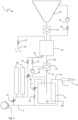
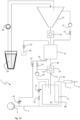
- Water-abrasive suspension cutting system 1 shown has a high-pressure source 3, which provides water in a high-pressure line 5 at a high pressure p 0 of approximately 1,500 to 4,000 bar.
- the high-pressure line 5 is connected to an outlet nozzle 7 from which the high-pressure water emerges in a jet 9 at very high speed. So that the jet 9 can be used effectively as a cutting jet for cutting material, the high-pressure line 5 is branched in such a way that at least part of the flow through the high-pressure line 5 is guided through a pressure vessel 11 in which a water-abrasive suspension 13 is located .
- the supply of the water-abrasive suspension 13 to the outlet nozzle can be switched on and off via a shut-off valve 15.
- the proportion of the water-abrasive suspension 13 in the jet 9 can be adjusted via a throttle 17 by throttling the flow rate in the secondary line of the high-pressure line 5 that runs through the pressure vessel 11.
- the throttle 17 can be designed to be static, for example in the form of a pinhole or adjustable or controllable.
- the throttle 17 is preferably adjustable, so that the throttle 17 can also completely shut off the inflow into the pressure vessel 11, so that the shut-off valve 15 can be dispensed with.
- the throttle 17 is preferably controllable, with a signal characteristic of the abrasive removal flow, which can be obtained from a sensor or an available operating parameter, being used as a controlled variable to regulate the opening of the throttle 17 (see Fig. 7a-c ).
- a refill valve 19 in the form of a ball valve is arranged above the pressure vessel 11.
- the refill valve 19 connects a lock chamber 21 arranged above the refill valve 19 with the pressure vessel 11.
- a filling valve 23 is in turn arranged above the lock chamber 21, which connects a refill funnel 25 arranged above the lock chamber 21 to the lock chamber 21.
- the filling valve 23 can be designed essentially identical to the refill valve 19 in the form of a ball valve.
- the refill funnel 25 is not under pressure, so that dry, moist or wet abrasive or a water-abrasive suspension can be filled in from above (see Figures 8-12 ).
- This can be at least partially an abrasive reprocessed from the cutting jet 9, which is conveyed via a conveyor device (see Figures 8-12 ) can be filled into the refill funnel 25 from above in dry, wet, frozen, pelletized or suspended form.
- the lock chamber 21 can be temporarily depressurized.
- a pressure in the lock chamber 21 can be released into a drain 29 via a pressure relief valve 27 in the form of a needle valve.
- the filling valve 23 can be opened so that abrasive falls from the refill funnel 25 into the lock chamber 21.
- This gravity-induced filling of the lock chamber 21 with abrasive can be supported and accelerated by a pump 31.
- the pump 31 can be connected to the lock chamber 21 on the suction side and to the refill funnel 25 on the pressure side. The pump 31 can thus suck abrasive into the lock chamber 21. This is above all This is particularly useful if abrasive agents clog the tapered lower area of the refill funnel 25 or the filling valve 23.
- the pump 31 does not have to be designed for high pressure, it is advantageous if the pump 31 can be shut off from the lock chamber 21 by means of a pump shut-off valve 33 in the form of a needle valve.
- the pump shut-off valve 33 can be designed to be flushable in order to flush the valve seat and the valve body, for example in the form of a valve needle, free of abrasive agents (see Figures 19a-b ). On the one hand, this ensures that the pump shut-off valve 33 closes tightly and reduces material wear in the valve.
- the pump 31 can be largely protected from abrasive agents by means of an upstream filter and/or separator (both not shown).
- the pump shut-off valve 33 is only opened when the lock chamber 21 is already depressurized. Therefore, for the pump shut-off valve 33, a first embodiment of the needle valve according to Fig. 19a can be used, in which a side flushing inlet and an opposite side flushing outlet are provided.
- the second embodiment of the needle valve is according to Fig. 19b more advantageous, in which a check valve is provided at the flushing inlet. Since the pressure relief valve 27 is opened at high pressure, the check valve prevents pressure release towards the flushing inlet.
- the flushing outlet can open into the drain 29, so that both the pressure release and the flushing agent release take place exclusively towards the drain 29 and not towards the flushing inlet.
- the lock chamber 21 has a printing entrance 35 in a lower area, via which the lock chamber 21 can be printed.
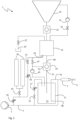
- the printing input 35 is in the exemplary embodiment Fig. 1 connected to a pressure accumulator 39 via a pressure valve 37 in the form of a needle valve and connected to the high-pressure line 5 via throttles 41, 42.
- the pressure accumulator 39 has two pressure accumulator units in the form of spring accumulators, which are connected in parallel to the inlet of the pressure valve 37.
- the pressure accumulator 39 is connected to the high-pressure line 5 via the throttle 41.
- the throttles 41, 42 can be designed to be static, for example in the form of perforated diaphragms, or adjustable or controllable. If the throttles 41, 42 can be adjusted to a degree at which the connection between the high-pressure line 5 and the pressure inlet 35 can be completely shut off, the pressure valve 37 can possibly be dispensed with.
- the pressure accumulator 39 is fully loaded with pressure before the lock chamber 21 is printed. As soon as the pressure valve 37 is opened, the pressure accumulator 39 discharges pressure into the lock chamber 21 and thus quickly pressurizes it to approximately 40% of the high pressure p 0 which is provided in the high pressure line 5 as nominal high pressure from the high pressure source 3.
- This rapid partial printing causes a pressure pulse to be introduced from below into the lock chamber 21, which loosens the abrasive. This is advantageous for later draining the abrasive into the pressure vessel 11.
- the high-pressure line 5 is also connected to the lock chamber 21 via the throttle 41, when the pressure valve 37 opens, there is also a throttled, ie slower, pressure through the high-pressure line 5.
- the pressure accumulator 39 As soon as the pressure accumulator 39 has been discharged of pressure, the remaining required pressure in the lock chamber 21 of approximately 60% of the nominal high pressure p 0 is built up exclusively via the throttled, ie slower, pressure from the high-pressure line 5. This limits the amplitude of the pressure drop in the high-pressure line 5 to a minimum.
- the pressure accumulator 39 is loaded with pressure again immediately from the moment in which it has discharged pressure.
- the high-pressure line 5 pressurizes both the lock chamber 21 with the residual pressure and the pressure accumulator 39. This is particularly advantageous if the pressure loading of the pressure accumulator 39 is so time-consuming that the refill passage rate depends on the pressure loading time of the pressure accumulator 39.
- the pressure accumulator 39 can be shut off with a pressure accumulator valve 43 in the form of a needle valve.
- the pressure accumulator valve 43 can be shut off in order not to additionally load the high-pressure line 5 with the pressure loading of the pressure accumulator 39 while the lock chamber 21 is being pressurized.
- Such a load could cause a pressure drop in the high-pressure line 5, which could have a negative influence on the cutting performance at the outlet nozzle 7. It is therefore advantageous to only open the pressure accumulator valve 43 when the lock chamber 21 is completely pressurized and the pressure valve 37 is closed so that the pressure accumulator 39 can be charged with pressure via the throttle 41 from the high-pressure line 5.
- the throttle 41 can be set so that the printing of the pressure accumulator 39 takes place as slowly as possible, but still fast enough so that before the next pass For printing on the lock chamber 21, the pressure accumulator 39 is completely loaded with pressure.
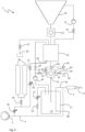
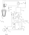
- a third embodiment according to Fig. 3 The pressure accumulator 39 is completely dispensed with and the lock chamber 21 is printed exclusively via the throttle 41 from the high-pressure line 5.
- the high-pressure source 3 for example via a servo pump control, can react so quickly to an initial pressure drop and adjust the pump performance accordingly quickly that a large amplitude of a pressure drop does not even occur.
- An initial pressure drop can be communicated to the high-pressure source 3 via pressure sensors, so that the high-pressure source 3 can quickly counteract a further pressure drop by increasing power or increasing the speed.
- the initial pressure drop can be mitigated via the throttle 41, so that there is never a pressure drop that significantly impairs the cutting performance.
- a delivery aid 45 is provided, for example in the form of a pump, which is connected to the pressure vessel 11 on the suction side and to the lock chamber 21 on the pressure side.
- the conveying aid 45 supports or generates the flow of abrasive agent from the lock chamber 21 downwards into the pressure vessel 11. It can prevent or solve blockages of abrasive agent and accelerate the refilling process caused by or supported by gravity.
- the delivery aid 45 works on the pressure vessel 11 with water under the nominal high pressure p 0 . It must therefore be designed for high-pressure operation. For example, as in Fig. 6b shown, only have an inductively driven paddle wheel in high pressure, so that the number of moving parts that are under high pressure is minimized.
- a conveyor shut-off valve 47 is arranged between the conveying aid 45 and the lock chamber 21, whereby the conveying aid shut-off valve 47 in the form of a needle valve can shut off the pump 47 from the lock chamber 21 if the lock chamber 21 is not or not completely pressurized.
- the delivery aid shut-off valve 47 is a flushable needle valve according to Fig. 19b with a check valve at the flush inlet as it is operated under high pressure.
- Fig. 6a-c show various alternative embodiments for the conveying aid 45.
- the conveying aid 45 can, for example, have an impeller driven from the outside via a shaft (see Fig. 6a ) or an inductively driven impeller (see Fig. 6b ).
- the delivery aid 45 can also support the refilling of abrasive into the pressure container 11 via a piston stroke (see Fig. 6c ).
- the delivery aid 45 can pump or convey continuously or for a limited time or in pulses. It may be sufficient if the abrasive flow into the pressure vessel 11 is only supported initially and then continues to run fast enough with the support of gravity alone. Alternatively or additionally, the abrasive flow into the pressure vessel 11 can be continuously supported or generated.
- the refill valve 19 In addition to an upper valve inlet 49 and a lower valve outlet 51, the refill valve 19 also has a side pressure inlet 53.
- a valve chamber in which a movable valve body is located can be printed via the pressure inlet 53. Without pressure on the valve chamber, it can happen that when the system is started up, the very high pressures on the valve inlet 49 and the valve outlet 51 press the valve body so strongly into the valve seat that the valve body can no longer be moved.
- a pressure equalization in the refill valve 19 can be created via the side pressure inlet 53, so that the valve body is movable after startup.
- a flushing for the refill valve 19 is provided.
- a flushing source 55 can be connected to the pressure inlet 53 in a lockable manner (see Fig. 4 ).
- Three flushing valves 57, 59, 61 are preferably provided to be able to switch the flushing on and off or to separate it from the high pressure.
- a first flushing valve 57 in the form of a needle valve is arranged between the delivery aid 45 and the pressure inlet 53.
- a second flushing valve 59 also referred to here as a flushing outlet valve 59, is arranged in the form of a needle valve between a side flushing outlet 63 and a drain 65.
- a third flushing valve 61 in the form of a needle valve is arranged between the flushing source 55 and the pressure inlet 53.
- the refill valve 19 In order to flush the refill valve 19 with water or a water-detergent mixture so that a valve chamber of the refill valve 19 can be freed from abrasive residue, the refill valve 19 is preferably closed.
- the first flushing valve 57 is also closed so that pressure can be released from the pressure inlet 53 without releasing the pressure at the delivery aid 45.
- the second flushing valve 59 is opened towards the drain 65 so that any high pressure that may exist can be drained from the valve chamber. If the third flushing valve 61 is now opened, water or a water-rinsing agent mixture flows through the valve chamber to the drain 65 and thus flushes it free of abrasive residue.
- the flushing of the refill valve 19 is preferably carried out as a service procedure when the system 1 is completely depressurized in order to be able to completely flush out the valve chamber and, if necessary, to be able to move the valve body.
- a flushing inlet 66 is provided separately from the pressure inlet 53 (see also Fig. 15a-b and 17a-b ).
- the pressure inlet 53 can be coaxial with a servo motor shaft 86 and this be arranged opposite each other, wherein the flushing inlet 66 and the flushing outlet 63 can be arranged transversely to the servo motor shaft 86 coaxially to one another and on opposite sides.
- the flushing is ended again by closing the three flushing valves 57, 59, 61 in the reverse order, i.e. the third flushing valve 61 is initially closed so that the flushing flow is stopped. Then the second flushing valve 59 is closed to close off the valve space from the drain 65. Finally, the first flushing valve 57 can be opened so that the valve chamber is pressurized with high pressure. Printing on the valve chamber is advantageous because a valve body in the refill valve 19 can be pressed so strongly into a valve seat due to the high pressure difference between the valve outlet 51 or valve inlet 49 and the valve chamber that it can no longer be moved. On the other hand, printing on the valve chamber creates a pressure equalization so that the valve body remains movable in the refill valve 19.
- FIG. 7a-c A preferred control of the abrasive removal flow is clarified.
- a branch of the high-pressure line 5 is guided through the pressure vessel 11 filled with abrasive suspension 13.
- a removal point 68 arranged in the lower region of the pressure vessel 11 is connected to the outlet nozzle 7 via an abrasive agent line 70, and a branch of the high-pressure line 5 is led into an upper region of the pressure vessel 11 via a control valve or controllable throttle 17.
- the abrasive agent line Downstream of the pressure vessel 11, the abrasive agent line is brought together again with the high-pressure line 5 in front of the outlet nozzle 7, so that the cutting jet contains, for example, abrasive agent suspension and water in a mixing ratio of 1:9.
- the mixing ratio is connected to the pressure vessel 11 on the input side Throttle or control valve 17 can be regulated.
- the control valve 17 When the control valve 17 is in its maximum opening position, the abrasive removal flow is at its maximum and the mixing ratio is at its maximum.
- a certain mixing ratio can be optimal for cutting certain materials, workpieces or workpiece sections, in which only as much abrasive is removed as necessary to achieve the cutting performance.
- the cutting performance can be adjusted via the mixing ratio during cutting.
- the refilling of the pressure container 11 with abrasive can be controlled in accordance with the abrasive removal flow so that there is always enough abrasive suspension 13 in the pressure container 11 for continuous cutting.
- Fig. 7a-c Four different filling levels of the abrasive in the pressure vessel 11 are indicated by dashed cones.
- the maximum fill level cone F max is defined by the fact that further refilling with abrasive into the pressure vessel 11 would result in a backflow into the refill valve 19.
- the minimum fill level cone F min is defined by the fact that as the abrasive is removed further, the proportion of abrasive increases Abrasive agent suspension in the outlet-side abrasive agent line 70 would decrease.
- level sensors 72, 74, 76 can be arranged on the pressure vessel 11 in order to signal that a level cone has been reached.
- the level sensors 72, 74, 76 can be, for example, ultrasonic sensors, optical sensors or barriers, electro-magnetic sensors or sensors of another type.
- the fill level sensors 72, 74, 76 are ultrasonic sensors that can signal when a fill level cone has been reached via a change in structure-borne noise.
- An upper fill level sensor 72 can, for example, signal that the fill level cone F 1 has been reached and start a timer or define a time t 1 .
- a lower fill level sensor 74 can, for example, signal that the fill level cone F 2 has been reached and stop a timer after ⁇ t or define a time t 2 .
- an average abrasive removal flow can be determined as ⁇ V/ ⁇ t or ⁇ V/(t 2 -t 1 ).
- the third lowest level sensor 76 can signal the minimum level cone F min and immediately cause the shut-off valve 15 to be shut off in order to prevent the pressure vessel 11 from being drained.
- Other operating parameters such as the pump speed of the high-pressure source 3 can also be used to determine the abrasive removal flow and its regulation as a controlled variable for the control valve 17.
- the abrasive agent flow or the mixing ratio can also be determined by means of a corresponding sensor 79 on the abrasive agent line 70 or in front of the outlet nozzle 7 and used as a control variable for the control valve 17.
- the level sensors 72, 74 can also be used to control or clock the refill cycles. For example, about the upper fill level sensor 72 between the fill level cone F 1 and the maximum fill level cone F max fits a filling of the lock chamber 21. If the fill level cone falls below F 1 , the upper fill level sensor 72 can trigger filling of the lock chamber 21 so that it is completely filled, when the lower fill level sensor 74 signals the fill level cone F 2 and can thus trigger refilling from the filled lock chamber 21 into the pressure vessel 11 . This prevents the level cone from sinking to the minimum level cone F min . At least one filling of the lock chamber 21 can also fit as a buffer between the minimum fill level cone F min and the fill level cone F 2 .
- the lock chamber 21 can always be automatically refilled immediately as soon as the refilling of the pressure vessel 11 has been completed. Then the refilling from the lock chamber 21 only needs to be triggered at the fill level cone F 2 .
- the vertical distance between the upper level sensor 72 and the lower level sensor 74 can be chosen to be relatively short, for example so short that a drop between F 1 and F 2 takes less time than a filling process of the lock chamber 21. With a shorter vertical distance, the average abrasive removal flow ⁇ V/ ⁇ t or ⁇ V/(t 2 -t 1 ) are determined more frequently and thus more accurately reflect the current abrasive removal flow dV/dt.
- Fig. 8 to 12 show various possibilities for adding abrasives in dry, wet, moist, suspended, frozen, pelletized or other form into the refill funnel 25 or directly into the filling valve 23.
- a preloading container 78 is provided, from which abrasive suspension is conveyed into the refill funnel 25 by means of a pump 80.
- water can flow out via an overflow 82 on the refill funnel and is displaced by the sinking abrasive.
- a preloading container 78 is provided, from which dry powdery or moist lumpy abrasive is conveyed into the refill funnel 25 by means of a screw conveyor 84 and/or a conveyor belt 85.
- water can also flow out via the overflow 82 on the refill funnel 25 and is displaced by the sinking abrasive.
- the abrasive can, for example, be recovered and processed from the wastewater of the cutting jet 9 after a cutting process, so that it can be used for a further cutting process.
- the advantage of this system over known water abrasive injection cutting systems is that such a reprocessed abrasive does not have to be dried and can be filled into the system in moist, lumpy or arbitrary form.
- Fig. 10 There is no overflow 82 provided, but rather a circuit between the refill funnel 25 and the preloading container 78, with the pump 80 on the outlet side of the refill funnel 25 driving the circuit for filling the refill funnel 25 with abrasive.
- the refill funnel 25 is preferably closed, so that the pump 80 can suck abrasive suspension from the preloading container 78.
- the advantage here is that the pump 80 delivers relatively clean water and not a saturated abrasive suspension as in Fig. 8 . This reduces wear in the pump 80. In addition, sucking the abrasive suspension is less prone to clogging than pushing it. As in Fig.
- a screw conveyor 84 can also be arranged on the input side of the refill funnel 25 in order to convey abrasive agents into the refill funnel 25. This is particularly advantageous if there is no abrasive suspension in the preloading container 78, but rather abrasive as a dry powder or in a moist, lumpy form.
- the refill funnel 25 can even be dispensed with completely (see Fig. 12 ), if the conveying via a screw conveyor 84 or a pump 80 takes place quickly enough and in a controlled manner directly into the filling valve 23.
- the water displaced by the abrasive when filling the lock chamber 21 can be returned from the lock chamber 21 to the refill funnel 25 via the pump shut-off valve 33.
- This can also be done with a pump 31 according to Fig. 1 to 5 be supported in order to actively suck abrasive agents into the lock chamber 21.
- the abrasive agent is refilled into the pressure vessel 11 in portions and cyclically, while a workpiece to be machined can be cut continuously with the cutting jet 9.
- Fig. 13 illustrates the process steps over time.
- a first step 301 water is provided under high pressure in the high-pressure line 5 by means of the high-pressure source 3.
- This then also provides a pressurized abrasive suspension in the pressure vessel 11 303.
- This means that a workpiece can then be cut by means of the high-pressure jet 9, which at least partially contains the abrasive suspension, while removing the abrasive suspension from the pressure vessel 11 305.
- Steps 307 to 311 are used for the portioned and cyclical refilling of the pressure container 11 with abrasive during the continuous cutting 305.
- the unprinted lock chamber 21 is filled with abrasive or an abrasive suspension 307.
- the conveying aid 45 is shut off from the unprinted lock chamber 21 by the conveying aid shut-off valve 47.
- the pump 31 is then shut off 308 from the lock chamber 21.
- the lock chamber is then at least partially pressurized 309 by discharging the pressure from the pressure accumulator 39, and finally the pressure container 11 is filled with abrasive or an abrasive suspension refilled 311 from the printed lock chamber 21 via the refill valve 19.
- the delivery aid 45 When refilling 311, the delivery aid 45 is fluidly connected to the printed lock chamber 21 via the opened delivery aid shut-off valve 47. After refilling 311, the delivery aid shut-off valve 47 as well as the pressure valve 37 and the refill valve 19 are shut off in order to be able to relieve the pressure from the lock chamber 21 via the pressure relief valve 27 into the process 29 for the next filling step.
- the pressure accumulator can be charged with pressure 313 via the throttle 41 from the high-pressure line 5.
- the lock chamber 21 can be at least partially over the throttle 41 can be printed 315 from the high-pressure line 5. This slow, throttled printing 315 from the high-pressure line 5 can last longer than the rapid printing 309 by discharging the pressure of the pressure accumulator 39.
- the printing 309 of the lock chamber 21 can be done by discharging the pressure of a pressure accumulator 39 during a first time window A and the printing 315 of the lock chamber 21 of the high pressure line 5 takes place during a second time window B, the first time window A and the second time window B at least partially overlapping, preferably at their beginning.
- the printing 309 of the lock chamber 21 by discharging the pressure from the pressure accumulator can be done so quickly that abrasive agent located in the lock chamber 21 is loosened by a pressure surge.
- the printing 309 of the lock chamber is carried out by discharging the pressure from the pressure accumulator 39, preferably into a lower area of the lock chamber 21, as there are any blockages of abrasive in a lower range are more likely than in an upper range.
- the printing inlet 35 of the lock chamber 21 is blocked off from the pressure accumulator 39 and/or the high-pressure line 5 during filling 307 and refilling 311.
- the pressure loading 313 of the pressure accumulator 39 can thus take place during filling 307 and/or refilling 311.
- Energy can be stored in the pressure accumulator 39 via spring or fluid compression, which can be designed, for example, as a spring or bladder accumulator.
- the filling 307, the printing 309 and the refilling 311 can take place cyclically while the cutting 305 can be carried out continuously.
- the pressure accumulator 39 can first be shut off by means of the pressure accumulator valve 43 by discharging the pressure of the pressure accumulator 39 from the high-pressure line 5.
- the pressure accumulator valve 43 can preferably only be opened again to pressurize the pressure accumulator 39 when the lock chamber 21 has been pressurized via the throttle 41 from the high-pressure line 5.
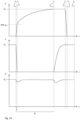
- Fig. 14 illustrates an exemplary course of the pressure p over time t in the lock chamber 21 (top), in the pressure accumulator 39 (middle) and in the high-pressure line 5 (bottom).
- the pressure in the unprinted lock chamber 21 is initially the ambient pressure, which is at the zero line here.
- the lock chamber 21 can be filled 307 in this unprinted phase before the start of printing 309 at time t 0 .
- Printing 309, 315 begins at time t 0 .
- the lock chamber 21 is now printed 309 to up to 40% of the nominal high pressure p 0 from the pressure discharge of the pressure accumulator 39.
- the pressure accumulator 39 is then discharged to a minimum at t 1 and is then via the pressure accumulator valve 43 according to the second exemplary embodiment Fig. 2 cordoned off.
- the printing 309, 315 of the lock chamber 21 can take 5 to 10 seconds.
- the refill valve 19 is opened so that abrasive can flow into the pressure vessel 11.
- the abrasive has completely flowed out of the lock chamber 21 into the pressure vessel 11 and the refill step 311 has been completed.
- the pressure from the lock chamber 21 can be released relatively quickly via the pressure relief valve 27 into the drain 29 until low pressure again prevails in the lock chamber 21 at t 4 .
- a new refill cycle can then start with filling 307 of the lock chamber 21.
- the pressure accumulator 39 is preferably loaded with pressure again as slowly as possible and throttled from t 2 onwards from the high-pressure line 5 in order to be fully pressure-loaded again at t 0 for printing 309.
- the lower graph shows the pressure drop in the high-pressure line 5 when the pressure valve 37 is opened at t 0 or the pressure accumulator valve 43 at t 2 .
- the amplitude of the pressure drop is each reduced via the throttle 41 to a level at which the cutting performance of the cutting jet 9 is not significantly impaired.
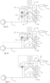
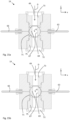
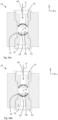
- FIGs 15a and 15b the refill valve 19 is shown in cross section in more detail in different opening positions. Since the refill valve 19 must be operated under high pressure on the valve inlet 49 and the valve outlet 51, trouble-free operation of the refill valve 19 is a technical challenge.
- the reliable opening and closing of the refill valve 19 is now preferably ensured by sub-aspects which, individually or in any combination of sub-aspects, contribute to ensuring that the refill valve 19 is not clogged or blocked by the abrasive.
- the refill valve 19 which is preferably designed as a ball valve, has a vertical flow direction D from top to bottom and has a centrally arranged valve body 67 with spherical outer surfaces that can be rotated about an axis of rotation R perpendicular to the flow direction D.
- the valve body 67 has a central opening 69, which is in the in Fig. 15a and Fig. 15b Opening positions shown runs parallel to the flow direction D and perpendicular to the axis of rotation R.
- the first opening position according to Fig. 15a differs from the second opening position Fig. 15b in that the valve body 67 is rotated by 180 ° with respect to the axis of rotation R.
- the valve body 67 sits in a valve space 71 between an upper valve seat 73 and a lower valve seat 75.
- the upper valve seat 73 forms the valve inlet 49 and the lower valve seat 75 forms the valve outlet 51.
- the upper valve seat 73 and the lower valve seat 75 are coaxial with one another and to the vertical flow direction D.
- the valve chamber 71 is connected via the lateral flushing inlet 66 and via the flushing outlet 63 diametrically opposite the flushing inlet 66. preferably flushable when the refill valve 19 is completely depressurized.
- the refill valve 19 is able to achieve a first closed position ( Fig. 16a ), a first opening position ( Fig. 15a ) and a second opening position ( Fig. 15b ), whereby in the first closed position ( Fig. 16a ) the lock chamber 21 is fluidly separated from the pressure vessel 11 and in the first and second opening positions ( Fig. 15a-b ) the lock chamber 21 is fluidly connected to the pressure vessel 11.
- the first opening position and the second opening position are essentially hardly distinguishable because of the symmetry of the valve body 67.
- the valve body 67 can be rotated as far as desired in one direction about the axis of rotation R, so that a reversal of the direction of rotation is in principle not necessary and the valve body 67 can only be actuated in one direction of rotation, provided that the torque required for this does not exceed a certain threshold value.
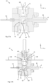
- the first closed position Fig. 16a is here at 90° between the first open position and the second open position. In this case there is also a second closing position (see Fig. 16b ), which is rotated by 180 ° about the axis of rotation R compared to the first closed position.
- the opening 69 runs into the in Fig. 16a and Fig.
- valve 16b shown closed positions both perpendicular to the flow direction D and perpendicular to the axis of rotation R, so that the valve body 67 seals the valve inlet 49 on the upper valve seat 73 and the valve outlet 51 on the lower valve seat 75.
- the optional flushing inlet 66 and flushing outlet 63 are not shown here, but can be provided be. This means that there are always two options for the direction of movement for the valve body 67, to open or close the refill valve 19 either to the first open position/closed position or to the second open position/closed position if a direction of movement currently requires too high a torque.
- valve body can 67 can be moved in the other direction of movement and the valve 19 can be brought into the other open position/closed position.
- the reversal can resolve the blockage or blockage so that the previously blocked direction of movement is free again the next time you press the button.
- the refill valve 19 can also be shaken free by turning it back and forth several times, for example if the valve body 67 is difficult to operate in both directions of movement.
- the valve chamber 71 can be printed in a closed position of the valve body 67.
- the valve chamber 71 has the pressure inlet 53, via which the valve chamber 71 can be printed in a closed position of the valve body 67.
- the pressure inlet 53 is arranged here in the yz plane coaxially with a servo motor shaft 86 opposite it.
- the pressure inlet 53 can also lie in the xz plane perpendicular thereto and, if necessary, be used as a flushing inlet 66 as required.
- the valve body 67 is rotated about the axis of rotation R via the servo motor shaft 86.
- valve chamber 71 When the initially unpressurized system 1 is put into operation or restarted, the valve chamber 71 is initially unpressurized. If the pressure vessel 11 and the lock chamber 21 are then pressurized to approximately 2,000 bar, the valve body 67 can be clamped in the valve chamber 71 by the valve seats 73, 75 due to the high pressure on the inlet and outlet sides and at the same time low pressure and can only be moved with difficulty or not at all. By means of the pressure inlet 53, the pressure difference between the valve chamber 71 and the valve inlet 49 or the valve outlet 51 can be largely reduced during startup, so that the valve body 67 is not clamped by the high pressure.
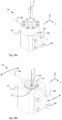
- the upper valve seat 73 is shown to be adjustable via an adjusting device according to a sub-aspect.
- the upper valve seat 73 can be positioned in the z direction via an external thread by rotating about the flow direction D. The rotation can be done by Lever 88 acting on the outside in attack surfaces 77 can be carried out manually or by motor.
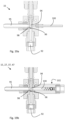
- the valve space is as in, for example Fig. 15a-b shown flushable.
- the refill valve has the flushing inlet 66 and the flushing outlet 63, via which the valve chamber 71 can be flushed through.
- the pressure inlet 53 can optionally serve as a flushing inlet 66. This is particularly advantageous in combination with the pressure inlet 53, since a flushing cycle can be carried out when the valve chamber 71 is depressurized or the system 1 is completely depressurized and then when the system 1 is put back into operation, the valve chamber 71 can be pressurized again via the pressure inlet 53 so that the valve body 67 is not trapped by the high pressure.
- the refill valve has the upper valve seat 73 on the input side and the lower valve seat 75 on the output side, with at least one of the valve seats 73, 75 being adjustable, so that the distance between the valve seats 73, 75 from one another is adjustable.
- the refill valve 19 can thus be optimally adjusted in order to be tight on the one hand and not to block on the other. It may be advantageous to readjust the distance between the valve seats 73, 75 from one another when the system is started up, in the event of temperature fluctuations, a stubborn blockage caused by abrasive agents and/or due to material wear. In order not to have to switch off the system and disassemble it, you can do as in Fig.
- a tool opening 90 can be provided through which a tool in the form of a lever 88 can reach in order to adjust the at least one adjustable valve seat 73.
- the adjustment of the valve seat 73 is preferably carried out in a service procedure with the system 1 unpressurized.
- the upper inlet-side valve seat 73 is axially adjustable along the flow direction D via an external thread.
- Lever 88 can have engagement surfaces 77 arranged on the circumference from the outside (see Fig. 18b ) can be applied to rotate the valve seat 73.
- the refill valve 19 therefore does not have to be separated from the system 1 or dismantled.
- the operating person can therefore intervene manually immediately to ensure continuous operation, or switch off the system 1 and depressurize it in order to adjust the valve seat 73 as a service procedure.
- the readjustment can also be carried out automatically and/or regulated via a motor.
- the valve body 67 is preferably rotated in a controlled manner about the axis of rotation R via a servo motor, not shown.
- the possibly measured torque or the power consumption of the motor can be monitored so that if a threshold value is exceeded, the direction of rotation can be changed to the other open position or closed position.
- torque or power peaks can be recorded over a certain period of time and an error or maintenance event can be signaled based on this recording. For example, the need for readjustment of the valve seat 73 can be displayed.
- Fig. 19a-b show two embodiments of flushable needle valves, which can be used, for example, as one or more of the shut-off valves 15, 27, 33, 37, 47 or elsewhere in the system 1.
- the needle valve according to Fig. 19a is preferably used where the needle valve does not have to open or close under high pressure, for example as a pump shut-off valve 33 in the circuit to support the filling of the lock chamber 21.
- the pump shut-off valve 33 has a high-pressure inlet 92, which is arranged coaxially with the high-pressure inlet 92 and axially Positionable needle 94 can be shut off with respect to a low pressure outlet 95.
- the needle 94 has a conical closing surface 96 at an end facing the high pressure inlet 92, which is used to shut off against a Valve seat 98 can be pressed. As soon as the high-pressure inlet 92 is shut off, high pressure can be applied to the high-pressure inlet 92 without it escaping via the low-pressure outlet 95. If there is no high pressure at the high pressure inlet 92, the pump shut-off valve 33 can be opened to allow low pressure flow from the high pressure inlet 92 to the low pressure outlet 95.
- the needle valve according to Fig. 19a-b also has a flushing inlet 100 through which the opened needle valve can be flushed, with flushing liquid, ie water or water with cleaning additives, being able to flow out via the low-pressure outlet 95.
- flushing liquid ie water or water with cleaning additives
- the valve seat 98 and the closing surface 96 in particular can be freed from abrasive residue in order to ensure clean closing with as little material wear as possible.
- the needle valve can be flushed shortly before the refill valve 19 closes.
- Fig. 19b shows a needle valve with a check valve 102 at the flushing inlet 100. The check valve 102 prevents backflow into the flushing inlet 100 and only allows flushing liquid to flow in the direction of the needle valve.
- the needle valve is used, for example, as one or more of the shut-off valves 15, 27, 37, 47, since the valve is opened there when there is high pressure at the high-pressure inlet 92. Without the check valve 102, this high pressure would at least partially discharge into the flushing inlet 100 and lead to a backflow into the flushing inlet 100.
- the check valve 102 prevents this and thus enables a clean pressure release via the low-pressure outlet 95.
- the low-pressure outlet 95 can also be a high-pressure outlet 95 in this case.
- the low-pressure outlet 95 is connected to a drain 29.
- the high pressure outlet is 95, however, is connected to the printing inlet 35 of the lock chamber 21 in order to apply high pressure to it.
- the needle valves are preferably operated pneumatically via a pressure plate (not shown).
- a pressure plate not shown.
- air pressure can be applied to the much larger pressure plate, so that the needle valve can be closed with a few bar of air pressure and kept tight against a high pressure of 1,500 bar and more.
Landscapes
- Engineering & Computer Science (AREA)
- Mechanical Engineering (AREA)
- General Engineering & Computer Science (AREA)
- Finish Polishing, Edge Sharpening, And Grinding By Specific Grinding Devices (AREA)
- Mechanical Treatment Of Semiconductor (AREA)
- Taps Or Cocks (AREA)
- Electrically Driven Valve-Operating Means (AREA)
- Details Of Valves (AREA)
Priority Applications (1)
| Application Number | Priority Date | Filing Date | Title |
|---|---|---|---|
| PL17717101.4T PL3600766T3 (pl) | 2017-03-31 | 2017-03-31 | Instalacja tnąca zawiesiną wodno-ścierną |
Applications Claiming Priority (1)
| Application Number | Priority Date | Filing Date | Title |
|---|---|---|---|
| PCT/EP2017/057783 WO2018177556A1 (de) | 2017-03-31 | 2017-03-31 | Wasser-abrasiv-suspensions-schneidanlage |
Publications (3)
| Publication Number | Publication Date |
|---|---|
| EP3600766A1 EP3600766A1 (de) | 2020-02-05 |
| EP3600766B1 true EP3600766B1 (de) | 2024-02-14 |
| EP3600766C0 EP3600766C0 (de) | 2024-02-14 |
Family
ID=58544915
Family Applications (1)
| Application Number | Title | Priority Date | Filing Date |
|---|---|---|---|
| EP17717101.4A Active EP3600766B1 (de) | 2017-03-31 | 2017-03-31 | Wasser-abrasiv-suspensions-schneidanlage |
Country Status (11)
| Country | Link |
|---|---|
| US (1) | US11305401B2 (pl) |
| EP (1) | EP3600766B1 (pl) |
| JP (1) | JP2020516467A (pl) |
| KR (1) | KR20190135512A (pl) |
| CN (1) | CN110753601A (pl) |
| AU (1) | AU2017406387A1 (pl) |
| BR (1) | BR112019019979A2 (pl) |
| CA (1) | CA3058487A1 (pl) |
| MX (1) | MX2019011523A (pl) |
| PL (1) | PL3600766T3 (pl) |
| WO (1) | WO2018177556A1 (pl) |
Families Citing this family (5)
| Publication number | Priority date | Publication date | Assignee | Title |
|---|---|---|---|---|
| US11577366B2 (en) | 2016-12-12 | 2023-02-14 | Omax Corporation | Recirculation of wet abrasive material in abrasive waterjet systems and related technology |
| EP3600768A1 (de) * | 2017-03-31 | 2020-02-05 | ANT Applied New Technologies AG | Wasser-abrasiv-suspensions-schneidanlage und verfahren zum wasser-abrasiv-suspensions-schneiden |
| WO2021021947A1 (en) * | 2019-07-29 | 2021-02-04 | Omax Corporation | Measuring abrasive flow rates in a conduit |
| US11518058B2 (en) * | 2019-12-16 | 2022-12-06 | Nienstedt Gmbh | Collecting and discharging device for the cutting jet of a liquid cutting system |
| US12403621B2 (en) | 2019-12-20 | 2025-09-02 | Hypertherm, Inc. | Motorized systems and associated methods for controlling an adjustable dump orifice on a liquid jet cutting system |
Citations (1)
| Publication number | Priority date | Publication date | Assignee | Title |
|---|---|---|---|---|
| DE69722383T2 (de) * | 1996-03-05 | 2004-03-18 | Hylsa S.A. De C.V., San Nicolas De Los Garza | Kugelventil zur durchflussreglung von feststoffpartikeln und gasen |
Family Cites Families (48)
| Publication number | Priority date | Publication date | Assignee | Title |
|---|---|---|---|---|
| US3605789A (en) * | 1970-05-04 | 1971-09-20 | Grove Valve & Regulator Co | Valve flushing system |
| US3731560A (en) * | 1971-10-20 | 1973-05-08 | Milbar Corp | Adjustable spanner wrench |
| US4203460A (en) * | 1978-03-15 | 1980-05-20 | Hills-Mccanna Company | Ball valve with compound closure movement |
| US4262688A (en) * | 1979-05-25 | 1981-04-21 | Acf Industries, Incorporated | Metal seat assemblies for valves |
| EP0161056A3 (en) | 1984-04-10 | 1988-03-16 | M & D VALVES LIMITED | Ball valve |
| US4816987A (en) * | 1985-06-28 | 1989-03-28 | Electric Power Research Institute, Inc. | Microprocessor-based control and diagnostic system for motor operated valves |
| CA1298708C (en) | 1985-10-10 | 1992-04-14 | Roger Artinade Heron | Feeding abrasive material |
| US4723387A (en) * | 1986-10-06 | 1988-02-09 | Ingersoll-Rand Company | Abrasive-jet cutting system |
| JPH02141772U (pl) * | 1989-04-28 | 1990-11-29 | ||
| FR2646488B1 (fr) * | 1989-04-28 | 1991-07-26 | Vanatome | Robinet a tournant spherique |
| JPH0740797Y2 (ja) * | 1991-10-11 | 1995-09-20 | 株式会社フクハラ | ドレーン排出装置 |
| US5594175A (en) * | 1994-05-06 | 1997-01-14 | Massachusetts Institute Of Technology | Apparatus and method for non-invasive diagnosis and control of motor operated valve condition |
| US5643058A (en) * | 1995-08-11 | 1997-07-01 | Flow International Corporation | Abrasive fluid jet system |
| US5722801A (en) * | 1995-12-21 | 1998-03-03 | The Young Industries, Inc. | Material conveying system with flow rate control |
| US5842683A (en) * | 1997-04-07 | 1998-12-01 | Upsoon Industrial Co., Ltd. | Structure of a ball valve especially used in food processing |
| US6279870B1 (en) * | 1998-03-27 | 2001-08-28 | Maxon Corporation | Intelligent valve actuator |
| IT1321196B1 (it) * | 1999-01-26 | 2003-12-30 | Duk-Jo Jun | Dispositivo per l'apertura/chiusura di una valvola e relativo metodo |
| US6669171B1 (en) * | 1999-10-29 | 2003-12-30 | Aceco Valve, Inc. | Compact manifold trunnion ball valve |
| US20030006729A1 (en) * | 1999-11-01 | 2003-01-09 | Raymond Woodworth D. | Rotary servovalve with precision controller |
| JP2001165335A (ja) | 1999-12-08 | 2001-06-22 | Hisaka Works Ltd | バルブ |
| KR100397759B1 (ko) | 2000-01-24 | 2003-09-13 | 주식회사 세우콘벨 | 볼 밸브의 개폐장치 |
| ES2220318T3 (es) | 2000-10-20 | 2004-12-16 | Ant Applied New Technologies Ag | Procedimiento para llenar un deposito a presion y dispositivo para generar un chorro de una suspension. |
| US6578598B2 (en) * | 2001-10-05 | 2003-06-17 | J.V.P. Inc. | Valve having an inner washing structure |
| US20040206404A1 (en) * | 2003-04-21 | 2004-10-21 | Chih-Hung Yang | Rotatable ball valve assembly |
| US7013917B2 (en) * | 2003-06-05 | 2006-03-21 | Joseph Iii Thomas Anthony | Rotary valve |
| US7089960B2 (en) * | 2003-06-13 | 2006-08-15 | Tlv Co. Ltd. | Ball valve |
| CN101473312A (zh) * | 2006-04-21 | 2009-07-01 | 芙罗服务管理公司 | 旋转编码器频率分析 |
| EP1859901A1 (de) | 2006-05-23 | 2007-11-28 | ANT Applied New Technologies AG | Vorrichtung zum Flüssigkeitsabrasivsuspensionsstrahlen |
| GB0612944D0 (en) | 2006-06-29 | 2006-08-09 | Bhr Group Ltd | Water jet cutting apparatus |
| US20090032762A1 (en) * | 2007-08-03 | 2009-02-05 | Mogas Industries, Inc. | Flow Control Ball Valve |
| US7690626B2 (en) * | 2007-10-15 | 2010-04-06 | Stunkard Gerald A | Ball valve having self-centering seats |
| WO2010115625A2 (de) | 2009-04-08 | 2010-10-14 | Axel Ahnert | Verfahren zur steuerung der ventile einer umlaufkolben-dampfmaschine |
| DE102011101074B4 (de) * | 2011-05-06 | 2013-11-07 | Altek Gesellschaft für allg. Landtechnik mbH | Kugelhahn für eine fluidführende Vorrichtung eines Nutzfahrzeugs |
| CN102777622A (zh) | 2011-05-10 | 2012-11-14 | 严俭祥 | 可调节补偿阀球磨损的球阀 |
| EP2755802B1 (de) | 2011-09-14 | 2016-04-06 | ANT Applied New Technologies AG | Wasser-abrasiv-suspensions-schneidanlage |
| CN102401148A (zh) * | 2011-11-17 | 2012-04-04 | 浙江凯瑞特阀业有限公司 | 可调式浮动球阀 |
| GB201204253D0 (en) * | 2012-03-11 | 2012-04-25 | Miller Donald S | Abrasive suspension feed system |
| WO2013142833A1 (en) * | 2012-03-22 | 2013-09-26 | Mogas Industries, Inc. | Multiport severe service ball valve |
| CN202580104U (zh) | 2012-05-23 | 2012-12-05 | 南通海狮船舶机械有限公司 | 一种高压球阀 |
| US9586306B2 (en) * | 2012-08-13 | 2017-03-07 | Omax Corporation | Method and apparatus for monitoring particle laden pneumatic abrasive flow in an abrasive fluid jet cutting system |
| US8881767B2 (en) * | 2013-02-25 | 2014-11-11 | Conbraco Industries, Inc. | Ball valve and seat assembly with life-sustaining flow |
| DE102013206097A1 (de) * | 2013-04-05 | 2014-10-09 | Airbus Operations Gmbh | Absperrventil |
| JP6224448B2 (ja) * | 2013-12-13 | 2017-11-01 | 株式会社キッツ | スラリー排出機能付きボールバルブとそのバルブキャビティからのスラリー排出方法 |
| EP3089849B2 (en) * | 2013-12-20 | 2024-02-21 | Flow International Corporation | Abrasive slurry delivery systems and methods |
| DE102014101794B4 (de) * | 2014-02-13 | 2020-02-13 | Hanon Systems | Vorrichtung zur Expansion von Kältemittel |
| KR102216007B1 (ko) | 2014-04-04 | 2021-02-16 | 안트 어플라이드 뉴 테크놀로지스 아게 | 물-연삭 현탁물 절단 설비 |
| CN104633168A (zh) | 2014-12-04 | 2015-05-20 | 张家港市佳晟机械有限公司 | 一种防淤积的球阀芯体 |
| CN105036310A (zh) | 2015-08-31 | 2015-11-11 | 太仓百诺纳米科技有限公司 | 一种防堵射流装置 |
-
2017
- 2017-03-31 JP JP2019553391A patent/JP2020516467A/ja active Pending
- 2017-03-31 MX MX2019011523A patent/MX2019011523A/es unknown
- 2017-03-31 CA CA3058487A patent/CA3058487A1/en not_active Abandoned
- 2017-03-31 PL PL17717101.4T patent/PL3600766T3/pl unknown
- 2017-03-31 US US16/498,744 patent/US11305401B2/en active Active
- 2017-03-31 KR KR1020197032243A patent/KR20190135512A/ko not_active Ceased
- 2017-03-31 CN CN201780091529.0A patent/CN110753601A/zh active Pending
- 2017-03-31 EP EP17717101.4A patent/EP3600766B1/de active Active
- 2017-03-31 AU AU2017406387A patent/AU2017406387A1/en not_active Abandoned
- 2017-03-31 WO PCT/EP2017/057783 patent/WO2018177556A1/de not_active Ceased
- 2017-03-31 BR BR112019019979A patent/BR112019019979A2/pt not_active Application Discontinuation
Patent Citations (1)
| Publication number | Priority date | Publication date | Assignee | Title |
|---|---|---|---|---|
| DE69722383T2 (de) * | 1996-03-05 | 2004-03-18 | Hylsa S.A. De C.V., San Nicolas De Los Garza | Kugelventil zur durchflussreglung von feststoffpartikeln und gasen |
Also Published As
| Publication number | Publication date |
|---|---|
| AU2017406387A1 (en) | 2019-10-17 |
| PL3600766T3 (pl) | 2024-07-01 |
| MX2019011523A (es) | 2019-11-18 |
| KR20190135512A (ko) | 2019-12-06 |
| JP2020516467A (ja) | 2020-06-11 |
| US20210107114A1 (en) | 2021-04-15 |
| BR112019019979A2 (pt) | 2020-04-28 |
| EP3600766C0 (de) | 2024-02-14 |
| EP3600766A1 (de) | 2020-02-05 |
| CN110753601A (zh) | 2020-02-04 |
| US11305401B2 (en) | 2022-04-19 |
| CA3058487A1 (en) | 2018-10-04 |
| WO2018177556A1 (de) | 2018-10-04 |
Similar Documents
| Publication | Publication Date | Title |
|---|---|---|
| EP3600765B1 (de) | Wasser-abrasiv-suspensions-schneidanlage und verfahren zum wasser-abrasiv-suspensions-schneiden | |
| EP3600766B1 (de) | Wasser-abrasiv-suspensions-schneidanlage | |
| EP2531696B1 (de) | Sprühdüseneinheit | |
| DE60212119T2 (de) | Schleifmittel-flüssigkeitsstrahl-vorrichtung | |
| EP3126094B1 (de) | Wasser-abrasiv-suspensions-schneidanlage | |
| EP3615273A1 (de) | Wasser-abrasiv-suspensions-schneidanlage | |
| DE102014015589A1 (de) | Fluidabgabevorrichtung, Einsprühvorrichtung, Bodenfräsmaschine und Verfahren | |
| EP3532245B1 (de) | Vorrichtung zum abrasiven fluidstrahlschneiden | |
| DE102005049941A1 (de) | Selbstentleerender Separator und Verfahren zu dessen Betrieb | |
| EP3237114B1 (de) | Feststoff-ausbringmodul | |
| EP3600767B1 (de) | Wasser-abrasiv-suspensions-schneidanlage und verfahren zum wasser-abrasiv-suspensions-schneiden | |
| EP2123402B1 (de) | Trockeneisstrahlvorrichtung | |
| AT399362B (de) | Verfahren und vorrichtung zum regeln des abflusses | |
| DE102014111043A1 (de) | Vorrichtung und Verfahren zum Strahlen von Suspension auf Werkstücke | |
| CH715046A2 (de) | Verfahren und Vorrichtung zur Elimination von Mikroverunreinigungen. | |
| DE102005055697B4 (de) | Vorrichtung zur dosierten Abgabe eines Fluids und Gerät mit einer solchen Vorrichtung | |
| CH705773B1 (de) | Schubzentrifuge und Verfahren zum Betreiben einer Schubzentrifuge. | |
| EP3263781A1 (de) | Einlaufgarnitur | |
| EP3600768A1 (de) | Wasser-abrasiv-suspensions-schneidanlage und verfahren zum wasser-abrasiv-suspensions-schneiden | |
| EP1626225B1 (de) | Einrichtung zur Zuführung von Schmierstoff | |
| WO2013079490A2 (de) | Vorrichtung und verfahren zum nassstrahlen von strahlgut | |
| DE19720528A1 (de) | Vorrichtung und Verfahren zum Vermischen eines ersten Fluids mit einem zweiten Fluid | |
| EP4406635B1 (de) | Vorrichtung und verfahren zum erzeugen eines druckluftimpulses | |
| DE19742062A1 (de) | Wasserversorgungsanlage und Volumenstromsensor | |
| EP1321560A2 (de) | Einrichtung und Verfahren zum Dosieren pastöser Produkte |
Legal Events
| Date | Code | Title | Description |
|---|---|---|---|
| STAA | Information on the status of an ep patent application or granted ep patent |
Free format text: STATUS: UNKNOWN |
|
| STAA | Information on the status of an ep patent application or granted ep patent |
Free format text: STATUS: THE INTERNATIONAL PUBLICATION HAS BEEN MADE |
|
| PUAI | Public reference made under article 153(3) epc to a published international application that has entered the european phase |
Free format text: ORIGINAL CODE: 0009012 |
|
| STAA | Information on the status of an ep patent application or granted ep patent |
Free format text: STATUS: REQUEST FOR EXAMINATION WAS MADE |
|
| 17P | Request for examination filed |
Effective date: 20190926 |
|
| AK | Designated contracting states |
Kind code of ref document: A1 Designated state(s): AL AT BE BG CH CY CZ DE DK EE ES FI FR GB GR HR HU IE IS IT LI LT LU LV MC MK MT NL NO PL PT RO RS SE SI SK SM TR |
|
| AX | Request for extension of the european patent |
Extension state: BA ME |
|
| DAV | Request for validation of the european patent (deleted) | ||
| DAX | Request for extension of the european patent (deleted) | ||
| STAA | Information on the status of an ep patent application or granted ep patent |
Free format text: STATUS: EXAMINATION IS IN PROGRESS |
|
| 17Q | First examination report despatched |
Effective date: 20211011 |
|
| 17Q | First examination report despatched |
Effective date: 20211022 |
|
| GRAP | Despatch of communication of intention to grant a patent |
Free format text: ORIGINAL CODE: EPIDOSNIGR1 |
|
| STAA | Information on the status of an ep patent application or granted ep patent |
Free format text: STATUS: GRANT OF PATENT IS INTENDED |
|
| INTG | Intention to grant announced |
Effective date: 20231005 |
|
| GRAS | Grant fee paid |
Free format text: ORIGINAL CODE: EPIDOSNIGR3 |
|
| GRAA | (expected) grant |
Free format text: ORIGINAL CODE: 0009210 |
|
| STAA | Information on the status of an ep patent application or granted ep patent |
Free format text: STATUS: THE PATENT HAS BEEN GRANTED |
|
| AK | Designated contracting states |
Kind code of ref document: B1 Designated state(s): AL AT BE BG CH CY CZ DE DK EE ES FI FR GB GR HR HU IE IS IT LI LT LU LV MC MK MT NL NO PL PT RO RS SE SI SK SM TR |
|
| REG | Reference to a national code |
Ref country code: GB Ref legal event code: FG4D Free format text: NOT ENGLISH |
|
| REG | Reference to a national code |
Ref country code: CH Ref legal event code: EP |
|
| REG | Reference to a national code |
Ref country code: DE Ref legal event code: R096 Ref document number: 502017015828 Country of ref document: DE |
|
| REG | Reference to a national code |
Ref country code: IE Ref legal event code: FG4D Free format text: LANGUAGE OF EP DOCUMENT: GERMAN |
|
| U01 | Request for unitary effect filed |
Effective date: 20240301 |
|
| U07 | Unitary effect registered |
Designated state(s): AT BE BG DE DK EE FI FR IT LT LU LV MT NL PT SE SI Effective date: 20240307 |
|
| U20 | Renewal fee for the european patent with unitary effect paid |
Year of fee payment: 8 Effective date: 20240314 |
|
| PG25 | Lapsed in a contracting state [announced via postgrant information from national office to epo] |
Ref country code: IS Free format text: LAPSE BECAUSE OF FAILURE TO SUBMIT A TRANSLATION OF THE DESCRIPTION OR TO PAY THE FEE WITHIN THE PRESCRIBED TIME-LIMIT Effective date: 20240614 |
|
| PGFP | Annual fee paid to national office [announced via postgrant information from national office to epo] |
Ref country code: GB Payment date: 20240403 Year of fee payment: 8 |
|
| PG25 | Lapsed in a contracting state [announced via postgrant information from national office to epo] |
Ref country code: GR Free format text: LAPSE BECAUSE OF FAILURE TO SUBMIT A TRANSLATION OF THE DESCRIPTION OR TO PAY THE FEE WITHIN THE PRESCRIBED TIME-LIMIT Effective date: 20240515 |
|
| PG25 | Lapsed in a contracting state [announced via postgrant information from national office to epo] |
Ref country code: RS Free format text: LAPSE BECAUSE OF FAILURE TO SUBMIT A TRANSLATION OF THE DESCRIPTION OR TO PAY THE FEE WITHIN THE PRESCRIBED TIME-LIMIT Effective date: 20240514 Ref country code: HR Free format text: LAPSE BECAUSE OF FAILURE TO SUBMIT A TRANSLATION OF THE DESCRIPTION OR TO PAY THE FEE WITHIN THE PRESCRIBED TIME-LIMIT Effective date: 20240214 |
|
| PGFP | Annual fee paid to national office [announced via postgrant information from national office to epo] |
Ref country code: CH Payment date: 20240502 Year of fee payment: 8 |
|
| PG25 | Lapsed in a contracting state [announced via postgrant information from national office to epo] |
Ref country code: ES Free format text: LAPSE BECAUSE OF FAILURE TO SUBMIT A TRANSLATION OF THE DESCRIPTION OR TO PAY THE FEE WITHIN THE PRESCRIBED TIME-LIMIT Effective date: 20240214 |
|
| PGFP | Annual fee paid to national office [announced via postgrant information from national office to epo] |
Ref country code: CZ Payment date: 20240328 Year of fee payment: 8 |
|
| PG25 | Lapsed in a contracting state [announced via postgrant information from national office to epo] |
Ref country code: RS Free format text: LAPSE BECAUSE OF FAILURE TO SUBMIT A TRANSLATION OF THE DESCRIPTION OR TO PAY THE FEE WITHIN THE PRESCRIBED TIME-LIMIT Effective date: 20240514 Ref country code: NO Free format text: LAPSE BECAUSE OF FAILURE TO SUBMIT A TRANSLATION OF THE DESCRIPTION OR TO PAY THE FEE WITHIN THE PRESCRIBED TIME-LIMIT Effective date: 20240514 Ref country code: IS Free format text: LAPSE BECAUSE OF FAILURE TO SUBMIT A TRANSLATION OF THE DESCRIPTION OR TO PAY THE FEE WITHIN THE PRESCRIBED TIME-LIMIT Effective date: 20240614 Ref country code: HR Free format text: LAPSE BECAUSE OF FAILURE TO SUBMIT A TRANSLATION OF THE DESCRIPTION OR TO PAY THE FEE WITHIN THE PRESCRIBED TIME-LIMIT Effective date: 20240214 Ref country code: GR Free format text: LAPSE BECAUSE OF FAILURE TO SUBMIT A TRANSLATION OF THE DESCRIPTION OR TO PAY THE FEE WITHIN THE PRESCRIBED TIME-LIMIT Effective date: 20240515 Ref country code: ES Free format text: LAPSE BECAUSE OF FAILURE TO SUBMIT A TRANSLATION OF THE DESCRIPTION OR TO PAY THE FEE WITHIN THE PRESCRIBED TIME-LIMIT Effective date: 20240214 |
|
| PGFP | Annual fee paid to national office [announced via postgrant information from national office to epo] |
Ref country code: PL Payment date: 20240328 Year of fee payment: 8 |
|
| PG25 | Lapsed in a contracting state [announced via postgrant information from national office to epo] |
Ref country code: SM Free format text: LAPSE BECAUSE OF FAILURE TO SUBMIT A TRANSLATION OF THE DESCRIPTION OR TO PAY THE FEE WITHIN THE PRESCRIBED TIME-LIMIT Effective date: 20240214 |
|
| PG25 | Lapsed in a contracting state [announced via postgrant information from national office to epo] |
Ref country code: SK Free format text: LAPSE BECAUSE OF FAILURE TO SUBMIT A TRANSLATION OF THE DESCRIPTION OR TO PAY THE FEE WITHIN THE PRESCRIBED TIME-LIMIT Effective date: 20240214 |
|
| PG25 | Lapsed in a contracting state [announced via postgrant information from national office to epo] |
Ref country code: SM Free format text: LAPSE BECAUSE OF FAILURE TO SUBMIT A TRANSLATION OF THE DESCRIPTION OR TO PAY THE FEE WITHIN THE PRESCRIBED TIME-LIMIT Effective date: 20240214 Ref country code: SK Free format text: LAPSE BECAUSE OF FAILURE TO SUBMIT A TRANSLATION OF THE DESCRIPTION OR TO PAY THE FEE WITHIN THE PRESCRIBED TIME-LIMIT Effective date: 20240214 Ref country code: RO Free format text: LAPSE BECAUSE OF FAILURE TO SUBMIT A TRANSLATION OF THE DESCRIPTION OR TO PAY THE FEE WITHIN THE PRESCRIBED TIME-LIMIT Effective date: 20240214 |
|
| REG | Reference to a national code |
Ref country code: DE Ref legal event code: R097 Ref document number: 502017015828 Country of ref document: DE |
|
| PG25 | Lapsed in a contracting state [announced via postgrant information from national office to epo] |
Ref country code: MC Free format text: LAPSE BECAUSE OF FAILURE TO SUBMIT A TRANSLATION OF THE DESCRIPTION OR TO PAY THE FEE WITHIN THE PRESCRIBED TIME-LIMIT Effective date: 20240214 |
|
| PG25 | Lapsed in a contracting state [announced via postgrant information from national office to epo] |
Ref country code: MC Free format text: LAPSE BECAUSE OF FAILURE TO SUBMIT A TRANSLATION OF THE DESCRIPTION OR TO PAY THE FEE WITHIN THE PRESCRIBED TIME-LIMIT Effective date: 20240214 |
|
| PLBE | No opposition filed within time limit |
Free format text: ORIGINAL CODE: 0009261 |
|
| STAA | Information on the status of an ep patent application or granted ep patent |
Free format text: STATUS: NO OPPOSITION FILED WITHIN TIME LIMIT |
|
| 26N | No opposition filed |
Effective date: 20241115 |
|
| PG25 | Lapsed in a contracting state [announced via postgrant information from national office to epo] |
Ref country code: IE Free format text: LAPSE BECAUSE OF NON-PAYMENT OF DUE FEES Effective date: 20240331 |
|
| PG25 | Lapsed in a contracting state [announced via postgrant information from national office to epo] |
Ref country code: IE Free format text: LAPSE BECAUSE OF NON-PAYMENT OF DUE FEES Effective date: 20240331 |
|
| PG25 | Lapsed in a contracting state [announced via postgrant information from national office to epo] |
Ref country code: CY Free format text: LAPSE BECAUSE OF FAILURE TO SUBMIT A TRANSLATION OF THE DESCRIPTION OR TO PAY THE FEE WITHIN THE PRESCRIBED TIME-LIMIT; INVALID AB INITIO Effective date: 20170331 |
|
| PG25 | Lapsed in a contracting state [announced via postgrant information from national office to epo] |
Ref country code: HU Free format text: LAPSE BECAUSE OF FAILURE TO SUBMIT A TRANSLATION OF THE DESCRIPTION OR TO PAY THE FEE WITHIN THE PRESCRIBED TIME-LIMIT; INVALID AB INITIO Effective date: 20170331 |
|
| PG25 | Lapsed in a contracting state [announced via postgrant information from national office to epo] |
Ref country code: CZ Free format text: LAPSE BECAUSE OF NON-PAYMENT OF DUE FEES Effective date: 20250331 |
|
| REG | Reference to a national code |
Ref country code: CH Ref legal event code: H13 Free format text: ST27 STATUS EVENT CODE: U-0-0-H10-H13 (AS PROVIDED BY THE NATIONAL OFFICE) Effective date: 20251023 |
|
| U90 | Renewal fees not paid: noting of loss of rights |
Free format text: RENEWAL FEE NOT PAID FOR YEAR 09 Effective date: 20251017 |
|
| GBPC | Gb: european patent ceased through non-payment of renewal fee |
Effective date: 20250331 |
|
| PG25 | Lapsed in a contracting state [announced via postgrant information from national office to epo] |
Ref country code: TR Free format text: LAPSE BECAUSE OF FAILURE TO SUBMIT A TRANSLATION OF THE DESCRIPTION OR TO PAY THE FEE WITHIN THE PRESCRIBED TIME-LIMIT Effective date: 20240214 |
|
| PG25 | Lapsed in a contracting state [announced via postgrant information from national office to epo] |
Ref country code: GB Free format text: LAPSE BECAUSE OF NON-PAYMENT OF DUE FEES Effective date: 20250331 |
|
| PG25 | Lapsed in a contracting state [announced via postgrant information from national office to epo] |
Ref country code: CH Free format text: LAPSE BECAUSE OF NON-PAYMENT OF DUE FEES Effective date: 20250331 |
|
| U93 | Unitary patent lapsed |
Free format text: RENEWAL FEE NOT PAID Effective date: 20250331 |