EP3598006B1 - Dunstabzugsvorrichtung für ein in ein möbel einbaubares kochfeld, verfahren zum betreiben der dunstabzugsvorrichtung und möbel mit kochfeld und mit dunstabzugsvorrichtung - Google Patents
Dunstabzugsvorrichtung für ein in ein möbel einbaubares kochfeld, verfahren zum betreiben der dunstabzugsvorrichtung und möbel mit kochfeld und mit dunstabzugsvorrichtung Download PDFInfo
- Publication number
- EP3598006B1 EP3598006B1 EP19185393.6A EP19185393A EP3598006B1 EP 3598006 B1 EP3598006 B1 EP 3598006B1 EP 19185393 A EP19185393 A EP 19185393A EP 3598006 B1 EP3598006 B1 EP 3598006B1
- Authority
- EP
- European Patent Office
- Prior art keywords
- air
- furniture
- air flow
- piece
- designed
- Prior art date
- Legal status (The legal status is an assumption and is not a legal conclusion. Google has not performed a legal analysis and makes no representation as to the accuracy of the status listed.)
- Active
Links
Images


Classifications
-
- F—MECHANICAL ENGINEERING; LIGHTING; HEATING; WEAPONS; BLASTING
- F24—HEATING; RANGES; VENTILATING
- F24C—DOMESTIC STOVES OR RANGES ; DETAILS OF DOMESTIC STOVES OR RANGES, OF GENERAL APPLICATION
- F24C15/00—Details
- F24C15/20—Removing cooking fumes
- F24C15/2042—Devices for removing cooking fumes structurally associated with a cooking range e.g. downdraft
-
- F—MECHANICAL ENGINEERING; LIGHTING; HEATING; WEAPONS; BLASTING
- F24—HEATING; RANGES; VENTILATING
- F24C—DOMESTIC STOVES OR RANGES ; DETAILS OF DOMESTIC STOVES OR RANGES, OF GENERAL APPLICATION
- F24C15/00—Details
- F24C15/20—Removing cooking fumes
- F24C15/2035—Arrangement or mounting of filters
Definitions
- Extractor device for a hob that can be built into a piece of furniture, method for operating the extractor device and system comprising a piece of furniture, a hob and an extractor device
- the invention relates to an extractor device for a hob that can be built into a piece of furniture, a method for operating the extractor device and a system comprising a piece of furniture and a hob and an extractor device.
- Extractor hoods with an exhaust duct can transport moisture that is released during a cooking process out of a building. With extractor hoods in recirculation mode, this moisture remains in the room.
- moist air can be blown into a cabinet plinth, such as the brochure US 2003/226 444 A1 disclosed.
- the air duct can end in the cabinet base, or the moist air can be directed out of the cabinet base into the kitchen area.
- the pamphlet WO 2004/054689 A1 shows an extractor device with filter devices for reducing the moisture in the conveyed air.
- the pamphlet US 2007/062 513 A1 discloses an extractor device which is installed with a hob in a piece of furniture and transports an air flow away from the surroundings of the hob into the interior of the piece of furniture.
- the pamphlet EP 2 893 967 A1 shows an embodiment of a filter for such an extractor device.
- an extractor device which has a line section with a filter above a furniture base, for example as a furniture drawer.
- the pamphlets DE 20 2006 003 321 U1 and DE 20 2006 016 179 U1 each show a similar extractor device for use in a piece of furniture that can be moved on wheels.
- the object of the invention is to create an improved extractor device for a hob that can be built into a piece of furniture, an improved method for operating the extractor device and an improved piece of furniture with a hob and with an extractor device.
- this object is achieved by an extractor device for a hob that can be built into a piece of furniture, a method for operating the extractor device and a piece of furniture with a hob and with an extractor device with the features or Steps of the main claims solved.
- the advantages that can be achieved with the invention are that the air humidity of the air or vapors extracted by the extractor device can be reduced.
- condensation of water vapor in the cabinet base or in the kitchen area can thereby be avoided.
- moisture damage to the furniture or the kitchen space can advantageously be avoided.
- a moisture adsorber of the extractor device can be arranged in the piece of furniture, which advantageously enables a compact design.
- the approach described here can be used accordingly in connection with a commercial or professional appliance, for example a professional kitchen appliance, or a laboratory ventilation system.
- An extractor device for a hob that can be built into a piece of furniture comprises at least one exhaust air line, a ventilation device, a circulating air device and a moisture adsorber.
- the piece of furniture has a plinth interior clad with a skirting board.
- the exhaust air line is designed to guide an air flow from an area surrounding the hob to the base interior.
- the ventilation device is designed to promote the air flow through the exhaust air line.
- the air circulation device has an odor filter for cleaning the air flow.
- the moisture adsorber is designed to remove moisture from the air flow.
- the furniture can be, for example, a kitchen cabinet in which the hob can be installed.
- the hob can be arranged, for example, in an upper section of the kitchen cabinet.
- the ventilation device can be, for example, a table-top ventilator which is designed to suck off vapor that is generated during a cooking process as an air stream.
- the exhaust air line can, for example, have an intake opening which is arranged adjacent to or adjacent to the hob.
- the intake opening can also be formed as part of the ventilation device.
- the exhaust air line can, for example, be arranged adjacent to the intake opening and additionally or alternatively to the ventilation device.
- the exhaust air line can, for example, run in sections along a side of the piece of furniture facing a wall of the kitchen space.
- the air circulation device can be arranged, for example, in the exhaust air line or in the base interior.
- the moisture adsorber can be, for example, an activated carbon filter which has a particularly high moisture absorption capacity and, additionally or alternatively, a particularly high tendency to give off moisture.
- the moisture adsorber can do this, for example be designed as a sorption filter with an open-pored, macroporous structure resulting from a very high level of chemical activation.
- the exhaust air line has a first line section which is shaped to guide the air flow out of the area surrounding the hob.
- the exhaust air line can have a second line section which is shaped to guide the air flow to an outlet gap in the skirting board.
- the first line section and, additionally or alternatively, the second line section can have a curvature for the air flow to bypass a corner of the piece of furniture. In this way, the air flow can advantageously be guided in a space-saving manner and can be discharged quickly and efficiently.
- this embodiment enables a compact design of the extractor hood device.
- the second line section can be tubular.
- the second line section can be formed as a deflection element to improve the directing of the air flow to the outlet gap in the skirting board.
- the deflection element can be, for example, a deflection plate or a line section of the exhaust air line formed from plastic.
- the air flow can advantageously be directed particularly efficiently through the tubular second line section or through the deflecting element to the outlet gap of the skirting board.
- the air circulation device can be arranged downstream of the first line section or downstream of the second line section. If the air circulation device is arranged downstream of the first line section, the air circulation device can be arranged, for example, between the first and the second line section. The air circulation device can be arranged in the base interior downstream of the second line section. The air circulation device can be arranged, for example, as a function of the shape of the piece of furniture, or as a function of the way in which the piece of furniture is positioned in the kitchen, which advantageously enables a compact design of the piece of furniture and the extractor device.
- the circulating air device can comprise the moisture adsorber.
- the moisture adsorber can be arranged, for example, adjacent to the odor filter in a housing of the circulating air device.
- This embodiment advantageously enables particularly efficient guidance of the air flow.
- the air circulation device and moisture adsorber can be arranged in series with respect to the air flow. If the moisture adsorber is connected downstream of the circulating air device, in particular the grease filter and / or the odor filter, then, for example, contamination of the moisture adsorber can be suppressed.
- the extractor device has a sensor device and a control device. The sensor device can be designed to sense air humidity and additionally or alternatively a temperature.
- the sensor device can include, for example, an air humidity sensor.
- the sensor device is designed to provide a sensor signal that maps the humidity and additionally or alternatively the temperature.
- the sensor signal can map a relative humidity.
- the control device is designed to provide a control signal for controlling the ventilation device using the sensor signal.
- the control device can, for example, be designed to provide the control signal for activating or deactivating the ventilation device as a function of a value of the sensor signal, or the control signal can be designed to set a ventilation output of the ventilation device.
- the ventilation device can be operated automatically by means of the sensor device and a control device according to Bedan, without requiring intervention by a user, which enables particularly efficient and thus energy-saving operation of the ventilation device.
- the control device is designed to provide the control signal for operating the ventilation device in a drying mode for drying the moisture adsorber as a function of a value of the sensor signal.
- the drying mode can, for example, take place after the cooking process.
- the ventilation device can, for example, have a lower fan power than when sucking off an air stream or vapors in an extraction mode during the cooking process.
- the control signal for operating the ventilation device in dry mode can be provided, for example, when the value of the sensor signal indicates that the humidity has reached or fallen below a predefined limit value, which corresponds, for example, to humidity sensed before starting the cooking process.
- the moisture adsorber can advantageously be regenerated for a subsequent cooking process by drying by means of the ventilation device.
- the method has at least one step of activating the ventilation device in an extraction mode and one step of activating the ventilation device in a dry mode.
- the ventilation device is activated in order to guide vapors generated during a cooking process as the air flow from the area surrounding the hob to the base interior.
- the ventilation device activated to guide room air as the air flow from the area surrounding the hob to the base interior after the cooking process in order to dry the moisture adsorber.
- the ventilation device can thus advantageously be used both for sucking off an air stream, for example a vapor, and for drying the moisture adsorber.
- the ventilation line of the ventilation device can advantageously be set in accordance with the extraction mode or the dry mode.
- the method can also include a step of deactivating the ventilation device after the step of activating the ventilation device in the extraction mode and before the step of activating the ventilation device in the dry mode.
- a step of deactivating the ventilation device after the step of activating the ventilation device in the extraction mode and before the step of activating the ventilation device in the dry mode.
- a piece of furniture is also presented with a hob built into the piece of furniture and with an exemplary embodiment of the above-mentioned extractor device that is built into the piece of furniture.
- the object on which the invention is based can also be advantageously achieved by means of this embodiment of the invention.
- Figure 1 shows a schematic representation of a piece of furniture 100 with an extractor device 105 for a hob that can be built into the piece of furniture 100 according to an exemplary embodiment.
- the furniture 100 has a plinth interior 115 clad with a plinth 110.
- the furniture 100 is an example of a kitchen cabinet with a cabinet base.
- the extractor device 105 comprises an exhaust air line 120, a ventilation device 125, a circulating air device 130 and a moisture adsorber 135.
- the exhaust air line 120 is designed to guide an air flow from an area surrounding the hob to the base interior 115.
- the exhaust air line 120 opens into the base interior 115, so that the air flow exits into the base interior 115.
- the ventilation device 125 is designed to promote the air flow through the exhaust air line 120.
- the air circulation device 130 has an odor filter 140 for cleaning the air flow.
- the moisture adsorber 135 is designed to remove moisture from the air flow.
- the air circulation device 130 comprises the moisture adsorber 135.
- the moisture adsorber 135 is arranged, for example, adjacent to the odor filter 140 in the air circulation device 130.
- the moisture adsorber 135 is connected upstream of the odor filter 140 in relation to a flow direction of the air flow.
- the ventilation device 125 is designed, for example, as a table-top ventilator and is correspondingly designed to suck in the air flow, for example vapors generated during a cooking process.
- the exhaust air line 120 directs the air flow through the circulating air device 130 and thus through the moisture adsorber 135 and for odor binding through the odor filter 140 into the base interior 115.
- the ventilation device 125 can be in another suitable position, for example within the exhaust air line 120, be arranged.
- the extractor device 105 also has an optional sensor device 145 and an optional control device 150.
- the sensor device 145 is designed to sense air humidity and additionally or alternatively a temperature.
- the sensor device 145 is designed to provide a sensor signal 155 which maps the humidity and additionally or alternatively the temperature.
- the control device 150 is designed to use the sensor signal 155 to generate a control signal 160 for controlling the ventilation device 125 provide.
- a sensor area of the sensor device 145 can for example be in the furniture 100, in the surroundings of the furniture 100 and within the extractor device 105, for example within the exhaust air line 120.
- control device 150 is designed to provide the control signal 160 for operating the ventilation device 125 in a dry mode for drying the moisture adsorber 135 as a function of a value of the sensor signal 155.
- the control signal 160 is provided, for example, when the air humidity reaches or falls below a predetermined value and additionally or alternatively the temperature for drying the moisture adsorber 135.
- drying of the moisture adsorber 135 can only begin when the control signal 160 indicates that the air sucked in to dry the moisture adsorber 135 is sufficiently dry.
- the use of the moisture adsorber 135 advantageously does not result in condensation of moisture in the air flow directed from the area surrounding the hob, which prevents damage to the furniture 100, for example through swelling damage or peeling edge strips can.
- the extractor device 105 shown here moisture peaks that arise as a result of the cooking process are reduced to physical values at which condensation of the water vapor does not occur in occupied rooms.
- the moisture adsorber 135 used is dried again after the cooking process when the air humidity prevailing before the cooking process has been restored as a result of the air exchange and the subsequent conditioning of the room air. This is done here by means of the control signal 160 using the sensor signal 155.
- the relative humidity behind the moisture adsorber 135 never exceeds values that can lead to moisture damage to the furniture 100 due to the adsorption kinematics of the moisture adsorber 135 used.
- the same physical conditions are established in the interior of the furniture as in the kitchen, that is to say in the surroundings of the furniture 100.
- a humidity sensor of the sensor device 145 in the kitchen senses the temperature and the humidity, whereby the point in time is recognized at which a fan of the ventilation device 125 is switched on in the dry mode with low air output to dry the moisture adsorber 135.
- the same physical properties are created by a fan run-on of the ventilation device 125 Conditions like in the kitchen.
- a dry moisture adsorber 135 is then available again for the next cooking process.
- the extractor device 105 shown here it is possible to end the air flow within the furniture 100 without risking long-term damage from moisture by setting the same physical conditions in the interior of the furniture 100 as in the kitchen.
- the moisture binding of the humidity of the air flow is permanently available because the moisture adsorber 135 is dried after each cooking process.
- the installation effort of the extractor device 105 is reduced compared to the variant in which the air is led out of the furniture 100. Compared to the routing of air out of the furniture 100, this also results in a lower outflow velocity and lower flow noise when the air flow is guided by means of the extractor device 105.
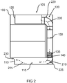
- Figure 2 shows a schematic representation of a piece of furniture 100 with an extractor device 105 for a hob that can be built into the piece of furniture 100 according to an exemplary embodiment.
- the furniture 100 shown here and the extractor device 105 shown here are similar to those based on FIG Figure 1 corresponding elements described.
- the arrows 205, 210 and 215 additionally show the guiding of the air flow in the extractor device 105.
- the exhaust air line 120 has a first line section 220 which is shaped to guide the air flow out of the area surrounding the hob.
- the exhaust air line 120 has a second line section 225 which is shaped to guide the air flow to an outlet gap 230 in the baseboard 110.
- the first line section 220 and, additionally or alternatively, the second line section 225 have a curvature for the air flow to bypass a corner of the furniture 100.
- the air flow is deflected in the first line section 225 by the bend, as the arrow 205 shows. In this case, the air flow is guided from the ventilation device 125 through the first line section 225 to the circulating air device 130.
- the air flow is then directed through the moisture adsorber 135 and through the odor filter 140 into the second line section 225, as the arrow 210 shows.
- the second line section 210 opens into the plinth interior 115. From the plinth interior 115, the air flow is diverted through the outlet gap 230 in the baseboard.
- the second line section 225 is shaped as a deflecting element to improve the directing of the air flow to the outlet gap 230 in the baseboard 110.
- the second line section 225 is tubular, as shown in the following Figures 3 and 5 shown
- the air circulation device 130 is arranged downstream of the first line section 220.
- the air circulation device can also be arranged downstream of the second line section 225, as shown on the basis of the following Figures 3 and 5 shown.
- the air flow is directed from the furniture 100 into the kitchen area.
- humidity is withdrawn from the air flow by means of the moisture adsorber 135. This advantageously prevents air humidity in the interior of the furniture 100 from condensing on the surfaces and causing damage.
- Figure 3 shows a schematic representation of a piece of furniture 100 with an extractor device 105 for a hob that can be built into the piece of furniture 100 according to an exemplary embodiment.
- the second line section 225 has a tubular shape.
- the air circulation device 130 with the odor filter 140 is arranged downstream of the second line section 225.
- the air circulation device is arranged in the plinth interior 115 of the furniture 100. This arrangement of the air circulation device 130 is advantageous, for example, if there is insufficient installation space for the air circulation device 130 in the section of the exhaust air line 120 behind the furniture 100, or if installation space is to be saved in this area.
- the tubular shape of the second line section 225 shown here is advantageous in order to prevent damage to the furniture 100 from air in the air flow that has not yet been dehumidified.
- the odor filter 140 is arranged here by way of example on a wall side of the air circulation device 130, and the moisture adsorber is arranged in the air circulation device 130 on the side of the odor filter facing away from the wall side, as shown in the following Figure 4 shown.
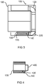
- FIG 4 shows a schematic representation of a circulating air device 130 with a moisture adsorber 135 according to an embodiment. It is a top view of the in Figure 3 air circulation device 130 shown.
- the air circulation device 130 has an inlet section 405 for introducing the air flow.
- Two odor filters 140 are arranged parallel to an axis of longitudinal extent of the circulating air device 130.
- One of the moisture adsorbers 135 is arranged on each of the sides of the odor filters 140 facing away from the wall sections of the circulating air device 130.
- the air flow introduced via the introduction section 405 is discharged again through the moisture adsorber 135 and the odor filter 140, which is based on the following Figures 5 and 6 is shown.
- the moisture adsorber 135 and the odor filter 140 can be cylindrical.
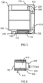
- FIG. 5 shows a schematic representation of a piece of furniture 100 with an extractor device 105 for a hob that can be built into the piece of furniture 100 according to an exemplary embodiment.
- the furniture 100 shown here and the extractor device 105 shown here correspond to that based on FIG Figure 3 described furniture and the extractor hood.
- the arrows 505, 510 and 515 are also shown to clarify the guiding of the air flow through the extractor device 105.
- the air flow is sucked in by means of the ventilation device 125 and passed through the first line section 220 of the exhaust air line 120, as the arrow 505 shows. From there, the air flow is passed on through the exhaust air line 120 to the tubular second line section 225, as the arrow 510 shows. From the second line section 225, the air flow is directed into the circulating air device 130, where the air flow is directed through the moisture absorber and through the odor filter 140 in the direction of the outlet gap 230 of the skirting board 110, as the arrow 515 shows.
- Figure 6 shows a schematic representation of a circulating air device 130 with a moisture adsorber 135 according to an embodiment. It is a top view of the in Figure 5 air circulation device 130 shown.
- the air flow is introduced into the air circulation device 130 through the introduction section 405, as three arrows 605 show.
- the odor filters 140 are arranged on the two wall sections parallel to the longitudinal extension axis of the circulating air device 130, and one of the moisture adsorbers 135 is arranged on each of the sides facing away from the wall sections of the circulating air device 130.
- the air flow introduced via the introduction section 405 is directed through the moisture adsorber 135 into the odor filter 140, and from there discharged from the circulating air device, which is shown by two arrows 610.
- FIG. 7 shows a flowchart of a method 700 for operating an extractor device according to an exemplary embodiment. This can be an extractor hood device as described with reference to the preceding figures.
- the method 700 has at least one step 705 of activating the ventilation device of the extractor device in an extraction mode and one step 710 of activating the ventilation device in a dry mode.
- a propeller of the ventilation device is set in rotation, for example.
- the ventilation device is activated in an extraction mode in order to guide fumes generated during a cooking process as the air flow from the area surrounding the hob to the interior of the plinth.
- the ventilation device is activated in a dry mode in order, after the cooking process, to guide room air as the air flow from the area surrounding the hob to the base interior in order to dry the moisture adsorber.
- the ventilation device can have a higher ventilation performance than in the dry mode.
- the method 700 also includes a step 715 of deactivating the ventilation device after step 705 of activating the ventilation device in the extraction mode.
- Step 715 is optionally carried out after step 705 and before step 710.
- Step 715 is optionally carried out in order to activate the drying mode of the ventilation device only when suitable air is available for drying, for example after the cooking process, or as soon as the air humidity has reached a certain limit value. In this way, after the operation of the ventilation device has ended in the extraction mode, the ventilation device can not be active for a period of time before the ventilation device is activated again in step 710.
- an exemplary embodiment of the extractor device as described with reference to the preceding figures can be operated.
- an exemplary embodiment comprises a “and / or” link between a first feature and a second feature, this is to be read in such a way that the exemplary embodiment according to one embodiment includes both the first feature and the second feature and, according to a further embodiment, either only the has the first feature or only the second feature.
Landscapes
- Engineering & Computer Science (AREA)
- Chemical & Material Sciences (AREA)
- Combustion & Propulsion (AREA)
- Mechanical Engineering (AREA)
- General Engineering & Computer Science (AREA)
- Ventilation (AREA)
Description
- Dunstabzugsvorrichtung für ein in ein Möbel einbaubares Kochfeld, Verfahren zum Betreiben der Dunstabzugsvorrichtung und System aus einem Möbel, einem Kochfeld und einer Dunstabzugsvorrichtung
- Die Erfindung betrifft eine Dunstabzugsvorrichtung für ein in ein Möbel einbaubares Kochfeld, ein Verfahren zum Betreiben der Dunstabzugsvorrichtung und ein System aus einem Möbel und einem Kochfeld und einer Dunstabzugsvorrichtung.
- Dunstabzüge mit einer Abluftleitung können Feuchtigkeit, die während eines Kochvorgangs freigesetzt wird, aus einem Gebäude heraus transportieren. Bei Dunstabzügen im Umluftbetrieb verbleibt diese Feuchtigkeit im Raum. Bei Dunstabzugssystemen mit einem Tischlüfter kann feuchte Luft in einen Schranksockel geblasen werden, wie beispielsweise die Druckschrift
US 2003 / 226 444 A1 offenbart. Die Luftführung kann dabei im Schranksockel enden, oder die feuchte Luft kann aus dem Schranksockel heraus in den Küchenraum geleitet werden. - Die Druckschrift
WO 2004/054689 A1 zeigt eine Dunstabzugseinrichtung mit Filtereinrichtungen zur Reduktion der Feuchtigkeit in der geförderten Luft. - Die Druckschrift
US 2007 / 062 513 A1 offenbart eine Dunstabzugseinrichtung, welche mit einem Kochfeld in einem Möbel eingebaut ist und einen Luftstrom von der Umgebung des Kochfeldes weg in das Innere des Möbels transportiert. Die DruckschriftEP 2 893 967 A1 zeigt für eine derartige Dunstabzugseinrichtung eine Ausgestaltung eines Filters. - Aus der Druckschrift
WO 2004/090425 A2 ist eine Dunstabzugseinrichtung bekannt, welche oberhalb eines Möbelsockels, beispielsweise als Möbelschublade ein Leitungsabschnitt mit einem Filter aufweist. Die DruckschriftenDE 20 2006 003 321 U1 undDE 20 2006 016 179 U1 zeigen jeweils eine ähnliche Dunstabzugseinrichtung zur Verwendung bei einem auf Rädern verfahrbarem Möbel. - Der Erfindung stellt sich die Aufgabe eine verbesserte Dunstabzugsvorrichtung für ein in ein Möbel einbaubares Kochfeld, ein verbessertes Verfahren zum Betreiben der Dunstabzugsvorrichtung und ein verbessertes Möbel mit einem Kochfeld und mit einer Dunstabzugsvorrichtung zu schaffen.
- Erfindungsgemäß wird diese Aufgabe durch eine Dunstabzugsvorrichtung für ein in ein Möbel einbaubares Kochfeld, ein Verfahren zum Betreiben der Dunstabzugsvorrichtung und ein Möbel mit einem Kochfeld und mit einer Dunstabzugsvorrichtung mit den Merkmalen bzw. Schritten der Hauptansprüche gelöst. Vorteilhafte Ausgestaltungen und Weiterbildungen der Erfindung ergeben sich aus den nachfolgenden Unteransprüchen.
- Die mit der Erfindung erreichbaren Vorteile bestehen darin, dass die Luftfeuchtigkeit der von der Dunstabzugsvorrichtung abgesaugten Luft oder Wrasen reduziert werden kann. Vorteilhafterweise kann dadurch eine Kondensation von Wasserdampf in dem Schranksockel oder in dem Küchenraum vermieden werden. Zudem können vorteilhafterweise Feuchtigkeitsschäden an dem Möbel oder dem Küchenraum vermieden werden. Ein Feuchtigkeitsadsorber der Dunstabzugsvorrichtung kann dabei in dem Möbel angeordnet sein, was vorteilhafterweise eine kompakte Bauweise ermöglicht.
- Auch wenn der beschriebene Ansatz anhand eines Haushaltgerätes beschrieben wird, kann der hier beschrieben Ansatz entsprechend im Zusammenhang mit einem gewerblichen oder professionellen Gerät, beispielsweise einem professionellen Küchengerät, oder einem Laborlüftungssystem eingesetzt werden.
- Eine Dunstabzugsvorrichtung für ein in ein Möbel einbaubares Kochfeld umfasst zumindest eine Abluftleitung, eine Lüftungseinrichtung, eine Umlufteinrichtung und einen Feuchtigkeitsadsorber. Das Möbel weist einen mit einer Sockelleiste verkleideten Sockelinnenraum auf. Die Abluftleitung ist dazu ausgeformt, einen Luftstrom aus einem Umgebungsbereich des Kochfelds zu dem Sockelinnenraum zu leiten. Die Lüftungseinrichtung ist dazu ausgebildet, den Luftstrom durch die Abluftleitung zu fördern. Die Umlufteinrichtung weist einen Geruchsfilter zum Reinigen des Luftstroms auf. Der Feuchtigkeitsadsorber ist dazu ausgebildet, dem Luftstrom Feuchtigkeit zu entziehen.
- Bei dem Möbel kann es sich beispielsweise um einen Küchenschrank handeln, in den das Kochfeld eingebaut werden kann. Das Kochfeld kann beispielsweise in einem oberen Abschnitt des Küchenschranks angeordnet sein. Bei der Lüftungseinrichtung kann es sich beispielsweise um einen Tischlüfter handeln, der dazu ausgeformt ist, als Luftstrom einen während eines Kochvorgangs entstehenden Wrasen abzusaugen. Die Abluftleitung kann beispielsweise eine Einzugsöffnung aufweisen, die benachbart zu oder angrenzend an das Kochfeld angeordnet ist. Die Einzugsöffnung kann auch als Teil der Lüftungseinrichtung ausgeformt sein. Die Abluftleitung kann beispielsweise an die Einzugsöffnung und zusätzlich oder alternativ an die Lüftungseinrichtung anschließend angeordnet sein. Die Abluftleitung kann beispielsweise abschnittsweise entlang einer einer Wand des Küchenraums zugewandten Seite des Möbels verlaufen. Die Umlufteinrichtung kann beispielsweise in der Abluftleitung oder in dem Sockelinnenraum anordenbar sein. Bei dem Feuchtigkeitsadsorber kann es sich beispielsweise um einen Aktivkohlefilter handeln, der eine besonders hohe Feuchtigkeitsaufnahmeleistung und zusätzlich oder alternativ eine besonders hohe Feuchtigkeitsabgabeneigung aufweist. Dazu kann der Feuchtigkeitsadsorber beispielsweise als Sorptionsfilter mit einer durch eine sehr hohe chemische Aktivierung entstehenden offenporigen, makroporösen Struktur ausgeformt sein.
- Gemäß der Erfindung weist die Abluftleitung einen ersten Leitungsabschnitt auf, der ausgeformt ist, den Luftstrom aus dem Umgebungsbereich des Kochfelds zu leiten. Zudem kann die Abluftleitung einen zweiten Leitungsabschnitt aufweisen, der ausgeformt ist, den Luftstrom zu einem Auslassspalt in der Sockelleiste zu leiten. Der erste Leitungsabschnitt und zusätzlich oder alternativ der zweite Leitungsabschnitt können eine Krümmung zum Vorbeileiten des Luftstroms an einer Ecke des Möbels aufweisen. Vorteilhafterweise kann der Luftstrom auf diese Weise platzsparend geleitet und schnell und effizient ausgeleitet werden. Zudem ermöglicht diese Ausführungsform eine kompakte Bauweise der Dunstabzugsvorrichtung.
- Der zweite Leitungsabschnitt kann gemäß einer Ausführungsform rohrförmig ausgeformt sein. Alternativ kann der zweite Leitungsabschnitt als Umlenkelement zur Verbesserung des Lenkens des Luftstroms zu dem Auslassspalt in der Sockelleiste ausgeformt sein. Bei dem Umlenkelement kann es sich beispielsweise um ein Umlenkblech handeln, oder um einen aus Kunststoff ausgeformten Leitungsabschnitt der Abluftleitung. Vorteilhafterweise kann der Luftstrom durch den rohrförmigen zweiten Leitungsabschnitt oder durch das Umlenkelement besonders effizient zum Auslassspalt der Sockelleiste gelenkt werden.
- Die Umlufteinrichtung kann gemäß einer Ausführungsform stromabwärts des ersten Leitungsabschnitts oder stromabwärts des zweiten Leitungsabschnitts angeordnet ist. Wenn die Umlufteinrichtung stromabwärts des ersten Leitungsabschnitts angeordnet ist, kann die Umlufteinrichtung beispielweise zwischen dem ersten und dem zweiten Leitungsabschnitt angeordnet sein. Stromabwärts des zweiten Leitungsabschnitts kann die Umlufteinrichtung in dem Sockelinnenraum angeordnet sein. Die Anordnung der Umlufteinrichtung kann beispielsweise in Abhängigkeit einer Ausformung des Möbels erfolgen, oder in Abhängigkeit einer Stellweise des Möbels in dem Küchenraum, was vorteilhafterweise eine kompakte Bauweise des Möbels und der Dunstabzugsvorrichtung ermöglicht.
- Zudem kann die Umlufteinrichtung gemäß einer Ausführungsform den Feuchtigkeitsadsorber umfassen. Dazu kann der Feuchtigkeitsadsorber beispielsweise benachbart zu dem Geruchsfilter in einem Gehäuse der Umlufteinrichtung angeordnet sein. Diese Ausführungsform ermöglicht vorteilhafterweise eine besonders effiziente Führung des Luftstroms. Generell können Umlufteinrichtung und Feuchtigkeitsadsorber bezüglich des Luftstroms in Reihe angeordnet sein. Ist der Feuchtigkeitsadsorber der Umlufteinrichtung, insbesondere dem Fettfilter und/oder dem Geruchsfilter nachgeschaltet, so kann beispielsweise eine Verschmutzung des Feuchtigkeitsadsorbers unterdrückt werden. Erfindungsgemäß weist die Dunstabzugsvorrichtung eine Sensoreinrichtung und eine Steuereinrichtung auf. Die Sensoreinrichtung kann ausgebildet sein, eine Luftfeuchtigkeit und zusätzlich oder alternativ eine Temperatur zu sensieren. Die Sensoreinrichtung kann beispielsweise einen Luftfeuchtigkeitssensor umfassen. Die Sensoreinrichtung ist ausgebildet, ein Sensorsignal bereitzustellen, das die Luftfeuchtigkeit und zusätzlich oder alternativ die Temperatur abbildet. Beispielsweise kann das Sensorsignal eine relative Luftfeuchtigkeit abbilden. Die Steuereinrichtung ist ausgebildet sein, unter Verwendung des Sensorsignals ein Steuersignal zum Ansteuern der Lüftungseinrichtung bereitzustellen.
- Die Steuereinrichtung kann beispielsweise ausgebildet sein, abhängig von einem Wert des Sensorsignals das Steuersignal zum Aktivieren oder Deaktivieren der Luftungseinrichtung bereitzustellen, oder das Steuersignal Kann ausgebildet sein, eine Luftungsleistung der Luftungseinrichtung einzustellen. Vorteillhafterweise Kann die Luftungseinrichtung mittels der Sensoreinrichtung una aer Steuereinrichtung nach Bedan automatisch betrieben werden, ohne einen Eingriff eines Benutzers erforderlich zu machen, was ein besonders effizientes und dadurch energiesparendes Betreiben der Lüftungseinrichtung ermöglicht.
- Erfindungsgemäß ist die Steuereinrichtung dazu ausgebildet, abhängig von einem Wert des Sensorsignals das Steuersignal zum Betreiben der Lüftungseinrichtung in einem Trockenmodus zum Trocknen des Feuchtigkeitsadsorbers bereitzustellen. Der Trockenmodus kann beispielsweise nach dem Kochvorgang erfolgen. In dem Trockenmodus kann die Lüftungseinrichtung beispielsweise eine geringere Gebläseleistung aufweisen als beim Absaugen eines Luftstroms oder Wrasens in einem Abzugsmodus während des Kochvorgangs. Das Steuersignal zum Betreiben der Lüftungseinrichtung in dem Trockenmodus kann beispielsweise bereitgestellt werden, wenn der Wfert des Sensorsignals ein Erreichen oder Unterschreiten eines vordefinierten Grenzwertes der Luftfeuchtigkeit anzeigt, der beispielsweise einer vor dem Starten des Kochvorgangs sensierten Luftfeuchtigkeit entspricht. Der Feuchtigkeitsadsorber kann durch das Trocknen mittels der Lüftungseinrichtung vorteilhafterweise für einen nachfolgenden Kochvorgang regeneriert werden. Mit diesem Ansatz wird zudem ein Verfahren zum Betreiben einer Ausführungsform der vorstehend genannten Dunstabzugsvorrichtung vorgestellt. Das Verfahren weist zumindest einen Schritt des Aktivierens der Lüftungseinrichtung in einem Abzugsmodus und einen Schritt des Aktivierens der Lüftungseinrichtung in einem Trockenmodus auf. Im Schritt des Aktivierens der Lüftungseinrichtung in dem Abzugsmodus wird die Lüftungseinrichtung aktiviert, um während eines Kochvorgangs entstehenden Wrasen als den Luftstrom aus dem Umgebungsbereich des Kochfelds zu dem Sockelinnenraum zu leiten. Im Schritt des Aktivierens der Lüftungseinrichtung in dem Trockenmodus wird die Lüftungseinrichtung aktiviert, um nach dem Kochvorgang Raumluft als den Luftstrom aus dem Umgebungsbereich des Kochfelds zu dem Sockelinnenraum zu leiten, um den Feuchtigkeitsadsorber zu trocknen. Vorteilhafterweise kann die Lüftungseinrichtung somit sowohl zum Absaugen eines Luftstroms, beispielsweise eines Wrasen, verwendet werden, als auch zum Trocknen des Feuchtigkeitsadsorbers. Zudem kann beim Aktivieren vorteilhafterweise die Lüftungsleitung der Lüftungseinrichtung entsprechend dem Abzugsmodus oder dem Trockenmodus eingestellt sein.
- Das Verfahren kann gemäß einer Ausführungsform zudem einen Schritt des Deaktivierens der Lüftungseinrichtung nach dem Schritt des Aktivierens der Lüftungseinrichtung in dem Abzugsmodus und vor dem Schritt des Aktivierens der Lüftungseinrichtung in dem Trockenmodus umfassen. Vorteilhafterweise ist es gemäß dieser Ausführungsform möglich, den Trockenmodus erst zu aktivieren, wenn zum Trocknen geeignete Luft zur Verfügung steht, beispielsweise nach dem Kochvorgang, oder sobald die Luftfeuchtigkeit nach Beenden des Kochvorgangs einen bestimmten Grenzwert erreicht hat.
- Es wird zudem ein Möbel mit einem in das Möbel eingebauten Kochfeld und mit einem Ausführungsbeispiel der vorstehend genannten Dunstabzugsvorrichtung, die in dem Möbel eingebaut ist, vorgestellt. Auch mittels dieser Ausführungsform der Erfindung kann die der Erfindung zugrundeliegende Aufgabe vorteilhaft gelöst werden.
- Ausführungsbeispiele der Erfindung sind in den Zeichnungen rein schematisch dargestellt und werden nachfolgend näher beschrieben. Es zeigt
- Figur 1
- eine schematische Darstellung eines Möbels mit einer Dunstabzugsvorrichtung für ein in das Möbel einbaubares Kochfeld gemäß einem Ausführungsbeispiel;
- Figur 2
- eine schematische Darstellung eines Möbels mit einer Dunstabzugsvorrichtung für ein in das Möbel einbaubares Kochfeld gemäß einem Ausführungsbeispiel;
- Figur 3
- eine schematische Darstellung eines Möbels mit einer Dunstabzugsvorrichtung für ein in das Möbel einbaubares Kochfeld gemäß einem Ausführungsbeispiel;
- Figur 4
- eine schematische Darstellung einer Umlufteinrichtung mit einem Feuchtigkeitsadsorber gemäß einem Ausführungsbeispiel;
- Figur 5
- eine schematische Darstellung eines Möbels mit einer Dunstabzugsvorrichtung für ein in das Möbel einbaubares Kochfeld gemäß einem Ausführungsbeispiel;
- Figur 6
- eine schematische Darstellung einer Umlufteinrichtung mit einem Feuchtigkeitsadsorber gemäß einem Ausführungsbeispiel; und
- Figur 7
- eine Ablaufdiagramm eines Verfahrens zum Betreiben der Dunstabzugsvorrichtung gemäß einem Ausführungsbeispiel.
- In der nachfolgenden Beschreibung günstiger Ausführungsbeispiele des vorliegenden Ansatzes werden für die in den verschiedenen Figuren dargestellten und ähnlich wirkenden Elemente gleiche oder ähnliche Bezugszeichen verwendet, wobei auf eine wiederholte Beschreibung dieser Elemente verzichtet wird.
-
Figur 1 zeigt eine schematische Darstellung eines Möbels 100 mit einer Dunstabzugsvorrichtung 105 für ein in das Möbel 100 einbaubares Kochfeld gemäß einem Ausführungsbeispiel. Das Möbel 100 weist einen mit einer Sockelleiste 110 verkleideten Sockelinnenraum 115 auf. Das Möbel 100 stellt beispielhaft einen Küchenschrank mit einem Schranksockel dar. - Die Dunstabzugsvorrichtung 105 umfasst eine Abluftleitung 120, eine Lüftungseinrichtung 125, eine Umlufteinrichtung 130 und einen Feuchtigkeitsadsorber 135. Die Abluftleitung 120 ist dazu ausgeformt, einen Luftstrom aus einem Umgebungsbereich des Kochfelds zu dem Sockelinnenraum 115 zu leiten. Gemäß einem Ausführungsbeispiel mündet die Abluftleitung 120 in den Sockelinnenraum 115, sodass der Luftstrom in den Sockelinnenraum 115 hinaus austritt. Die Lüftungseinrichtung 125 ist dazu ausgebildet, den Luftstrom durch die Abluftleitung 120 zu fördern. Die Umlufteinrichtung 130 weist einen Geruchsfilter 140 zum Reinigen des Luftstroms auf. Der Feuchtigkeitsadsorber 135 ist dazu ausgebildet ist, dem Luftstrom Feuchtigkeit zu entziehen.
- Gemäß dem hier gezeigten Ausführungsbeispiel umfasst die Umlufteinrichtung 130 den Feuchtigkeitsadsorber 135. Der Feuchtigkeitsadsorber 135 ist beispielhaft benachbart zu dem Geruchsfilter 140 in der Umlufteinrichtung 130 angeordnet. Dabei ist der Feuchtigkeitsadsorber 135 dem Geruchsfilter 140 in Bezug auf eine Strömungsrichtung des Luftstroms vorgeschaltet. Die Lüftungseinrichtung 125 ist beispielhaft als Tischlüfter ausgeführt und entsprechend dazu ausgebildet, den Luftstrom, beispielsweise während eines Kochvorgangs entstehende Wrasen, anzusaugen. In dem hier gezeigten Ausführungsbeispiel leitet die Abluftleitung 120 den Luftstrom durch die Umlufteinrichtung 130 und damit durch den Feuchtigkeitsadsorber 135 und zur Geruchsbindung durch den Geruchsfilter 140 in den Sockelinnenraum 115. Alternativ kann die Lüftungseinrichtung 125 an einer anderen geeigneten Position, beispielsweise innerhalb der Abluftleitung 120, angeordnet sein.
- Die Dunstabzugsvorrichtung 105 weist gemäß dem hier gezeigten Ausführungsbeispiel zudem eine optionale Sensoreinrichtung 145 und eine optionale Steuereinrichtung 150 auf. Die Sensoreinrichtung 145 ist ausgebildet, eine Luftfeuchtigkeit und zusätzlich oder alternativ eine Temperatur zu sensieren. Zudem ist die Sensoreinrichtung 145 ausgebildet, ein Sensorsignal 155 bereitzustellen, das die Luftfeuchtigkeit und zusätzlich oder alternativ die Temperatur abbildet. Die Steuereinrichtung 150 ist dazu ausgebildet, unter Verwendung des Sensorsignals 155 ein Steuersignal 160 zum Ansteuern der Lüftungseinrichtung 125 bereitzustellen. Ein Sensorbereich der Sensoreinrichtung 145 kann beispielsweise in dem Möbel 100, in einer Umgebung des Möbels 100 und innerhalb der Dunstabzugsvorrichtung 105, beispielsweise innerhalb der Abluftleitung 120 liegen.
- Ferner ist die Steuereinrichtung 150 gemäß einem Ausführungsbeispiel dazu ausgebildet, abhängig von einem Wert des Sensorsignals 155 das Steuersignal 160 zum Betreiben der Lüftungseinrichtung 125 in einem Trockenmodus zum Trocknen des Feuchtigkeitsadsorbers 135 bereitzustellen. Das Steuersignal 160 wird beispielsweise beim Erreichen oder Unterschreiten eines vorbestimmten Werts der Luftfeuchtigkeit und zusätzlich oder alternativ der Temperatur zum Trocknen des Feuchtigkeitsadsorbers 135 bereitgestellt. Dadurch kann beispielsweise erst dann mit einem Trocknen des Feuchtigkeitsadsorbers 135 begonnen werden, wenn das Steuersignal 160 anzeigt, das die zum Trocknen des Feuchtigkeitsadsorbers 135 angesaugte Luft ausreichend trocken ist.
- Bei dem Leiten des Luftstroms durch das Möbel 100 kommt es durch die Verwendung des Feuchtigkeitsadsorbers 135 vorteilhafterweise nicht zu einer Kondensation von Feuchtigkeit des aus dem Umgebungsbereich des Kochfelds geleiteten Luftstroms, wodurch eine Schädigung des Möbels 100, beispielsweise durch Quellschäden oder sich ablösenden Umleimer, verhindert werden kann. Mittels der hier gezeigten Dunstabzugsvorrichtung 105 werden Feuchtigkeitsspitzen, die durch den Kochvorgang entstehen, auf physikalische Werte, bei denen es in bewohnten Räumen nicht zur Kondensation des Wasserdampfs kommt, reduziert.
- Der eingesetzte Feuchtigkeitsadsorber 135 wird gemäß einem Ausführungsbeispiel nach dem Kochprozess wieder getrocknet, wenn sich durch den Luftwechsel und die anschließende Konditionierung der Raumluft die vor dem Kochprozess herrschende Luftfeuchtigkeit wieder eingestellt hat. Dies erfolgt hier mittels des Steuersignals 160 unter Verwendung des Sensorsignals 155. Bei der Trocknung des Feuchtigkeitsadsorbers 135 übersteigt die relative Luftfeuchtigkeit hinter dem Feuchtigkeitsadsorber 135 auf Grund der Adsorptionskinematik des eingesetzten Feuchtigkeitsadsorbers 135 niemals Werte, die zu Feuchtigkeitsschäden an dem Möbel 100 führen können. Außerdem ermöglicht ein Nachlauf der Lüftungseinrichtung 125 nach abgeschlossener Trocknung des Feuchtigkeitsadsorbers 135, dass sich in dem Inneren des Möbels die gleichen physikalischen Bedingungen wie in der Küche, also der Umgebung des Möbels 100 einstellen. Dazu sensiert ein Luftfeuchtigkeitssensor der Sensoreinrichtung 145 in der Küche die Temperatur und die Luftfeuchtigkeit, wodurch der Zeitpunkt erkannt wird, zu dem ein Gebläse der Lüftungseinrichtung 125 im Trockenmodus in kleiner Luftleistung zur Trocknung des Feuchtigkeitsadsorbers 135 eingeschaltet wird. Im Schrankinneren des Möbels 100 stellen sich durch einen Gebläsenachlauf der Lüftungseinrichtung 125 die gleichen physikalischen Bedingungen wie in der Küche ein. Für den nächsten Kochvorgang steht anschließend wieder ein trockener Feuchtigkeitsadsorbers 135 zur Verfügung.
- Mittels der hier gezeigten Dunstabzugsvorrichtung 105 ist es möglich, die Luftführung noch innerhalb des Möbels 100 zu beenden, ohne dabei Langzeitschäden durch Feuchtigkeit zu riskieren, durch ein Einstellen der gleichen physikalischen Bedingungen in dem Inneren des Möbels 100 wie in der Küche. Die Feuchtigkeitsbindung der Luftfeuchtigkeit des Luftstroms steht dauerhaft zur Verfügung, weil der Feuchtigkeitsadsorber 135 nach jedem Kochvorgang getrocknet wird. Dabei ist der Installationsaufwand der Dunstabzugsvorrichtung 105 gegenüber der Variante, bei der die Luft aus dem Möbel 100 heraus geführt wird, reduziert. Im Vergleich zu der Luftführung aus dem Möbel 100 heraus ergeben sich hier zudem eine geringere Ausströmgeschwindigkeit und geringere Strömungsgeräusche beim Leiten des Luftstroms mittels der Dunstabzugsvorrichtung 105. Ohne die Verwendung des Feuchtigkeitsabsorbers 135 würde feuchte Luft aus dem Möbel 100 herausgeleitet, wobei der Installationsaufwand höher ist, weil die Verrohrung an der Schrankrückwand herunter und auf dem Fußboden im Schranksockel bis zum gewünschten Ausblasfenster ausgeführt werden muss. Vorteilhafterweise kann durch das Verwenden des Feuchtigkeitsadsorbers 135 eine am Ausblasfenster auftretende hohe Ausströmgeschwindigkeit, die wiederum zu Zuglufterscheinungen oder erhöhten Strömungsgeräuschen führen kann, vermieden werden.
-
Figur 2 zeigt eine schematische Darstellung eines Möbels 100 mit einer Dunstabzugsvorrichtung 105 für ein in das Möbel 100 einbaubares Kochfeld gemäß einem Ausführungsbeispiel. Das hier gezeigte Möbel 100 und die hier gezeigte Dunstabzugsvorrichtung 105 ähneln den anhand vonFigur 1 beschriebenen entsprechenden Elementen. In dem hier gezeigten Ausführungsbeispiel ist durch die Pfeile 205, 210 und 215 zusätzlich das Leiten des Luftstroms in der Dunstabzugsvorrichtung 105 gezeigt. - Die Abluftleitung 120 weist gemäß einem Ausführungsbeispiel einen ersten Leitungsabschnitt 220 auf, der ausgeformt ist, den Luftstrom aus dem Umgebungsbereich des Kochfelds zu leiten. Zudem weist die Abluftleitung 120 einen zweiten Leitungsabschnitt 225 auf, der ausgeformt ist, den Luftstrom zu einem Auslassspalt 230 in der Sockelleiste 110 zu leiten. Der erste Leitungsabschnitt 220 und zusätzlich oder alternativ der zweite Leitungsabschnitt 225 weisen eine Krümmung zum Vorbeileiten des Luftstroms an einer Ecke des Möbels 100 auf. Der Luftstrom wird in dem ersten Leitungsabschnitt 225 durch die Krümmung umgelenkt, wie der Pfeil 205 zeigt. Dabei wird der Luftstrom von der Lüftungseinrichtung 125 durch den ersten Leitungsabschnitt 225 zu der Umlufteinrichtung 130 geleitet. Der Luftstrom wird dann durch den Feuchtigkeitsadsorber 135 und durch den Geruchsfilter 140 in den zweiten Leitungsabschnitt 225 geleitet, wie der Pfeil 210 zeigt. Der zweite Leitungsabschnitt 210 mündet in den Sockelinnenraum 115. Aus dem Sockelinnenraum 115 wird der Luftstrom durch den Auslasspalt 230 in der Sockelleiste hindurch ausgeleitet.
- Der zweite Leitungsabschnitt 225 ist in dem hier gezeigten Ausführungsbeispiel als Umlenkelement zur Verbesserung des Lenkens des Luftstroms zu dem Auslassspalt 230 in der Sockelleiste 110 ausgeformt. Gemäß einem alternativen Ausführungsbeispiel ist der zweite Leitungsabschnitt 225 rohrförmig ausgeformt, wie anhand der nachfolgenden
Figuren 3 und5 gezeigt - Die Umlufteinrichtung 130 ist gemäß dem hier gezeigten Ausführungsbeispiel stromabwärts des ersten Leitungsabschnitts 220 angeordnet. Alternativ kann die Umlufteinrichtung auch stromabwärts des zweiten Leitungsabschnitts 225 angeordnet sein, wie anhand der nachfolgenden
Figuren 3 und5 gezeigt. - Gemäß dem hier gezeigten Ausführungsbeispiel wird der Luftstrom aus dem Möbel 100 in den Küchenraum geleitet. Dabei wird dem Luftstrom mittels des Feuchtigkeitsadsorbers 135 Luftfeuchtigkeit entzogen. Dadurch wird vorteilhafterweise verhindert, dass Luftfeuchtigkeit im Inneren des Möbels 100 an den Oberflächen kondensiert und Schäden verursacht.
-
Figur 3 zeigt eine schematische Darstellung eines Möbels 100 mit einer Dunstabzugsvorrichtung 105 für ein in das Möbel 100 einbaubares Kochfeld gemäß einem Ausführungsbeispiel. In dem hier gezeigten Ausführungsbeispiel ist der zweite Leitungsabschnitt 225 rohrförmig ausgeformt. Zudem ist die Umlufteinrichtung 130 mit dem Geruchsfilter 140 stromabwärts des zweiten Leitungsabschnitts 225 angeordnet. Gemäß dem hier gezeigten Ausführungsbeispiel ist die Umlufteinrichtung in dem Sockelinnenraum 115 des Möbels 100 angeordnet. Diese Anordnung der Umlufteinrichtung 130 ist beispielsweise vorteilhaft, wenn in dem Abschnitt der Abluftleitung 120 hinter dem Möbel 100 nicht ausreichend Bauraum für die Umlufteinrichtung 130 vorhanden ist, oder wenn in diesem Bereich Bauraum eingespart werden soll. Wenn die Umlufteinrichtung 130 stromabwärts des zweiten Leitungsabschnitts 225 angeordnet ist, ist die hier gezeigte rohrförmige Ausformung des zweiten Leitungsabschnitts 225 vorteilhaft, um einer Schädigung des Möbels 100 durch noch nicht entfeuchtete Luft des Luftstroms vorzubeugen. Der Geruchsfilter 140 ist hier beispielhaft an einer Wandseite der Umlufteinrichtung 130 angeordnet, und der Feuchtigkeitsadsorber ist an der der Wandseite abgewandten Seite des Geruchsfilters in der Umlufteinrichtung 130 angeordnet, wie anhand der folgendenFigur 4 gezeigt. -
Figur 4 zeigt eine schematische Darstellung einer Umlufteinrichtung 130 mit einem Feuchtigkeitsadsorber 135 gemäß einem Ausführungsbeispiel. Es ist eine Draufsicht der inFigur 3 gezeigten Umlufteinrichtung 130 gezeigt. Die Umlufteinrichtung 130 weist einen Einleitabschnitt 405 zum Einleiten des Luftstroms auf. An den beiden Wandabschnitten parallel einer Längserstreckungsachse der Umlufteinrichtung 130 sind zwei Geruchsfilter 140 angeordnet. An den den Wandabschnitten der Umlufteinrichtung 130 abgewandten Seiten der Geruchsfilter 140 ist je einer der Feuchtigkeitsadsorber 135 angeordnet. Der über den Einleitabschnitt 405 eingeleitete Luftstrom wird durch die Feuchtigkeitsadsorber 135 und durch die Geruchsfilter 140 wieder ausgeleitet, was anhand der nachfolgendenFiguren 5 und 6 gezeigt ist. Alternativ können der Feuchtigkeitsadsorber 135 und der Geruchsfilter 140 zylinderförmig ausgeformt sein. -
Figur 5 zeigt eine schematische Darstellung eines Möbels 100 mit einer Dunstabzugsvorrichtung 105 für ein in das Möbel 100 einbaubares Kochfeld gemäß einem Ausführungsbeispiel. Das hier gezeigte Möbel 100 und die hier gezeigte Dunstabzugsvorrichtung 105 entsprechen dem anhand vonFigur 3 beschriebenen Möbel und der Dunstabzugsvorrichtung. In der hier gezeigten Darstellung sind zur Verdeutlichung des Führens des Luftstroms durch die Dunstabzugsvorrichtung 105 zusätzlich die Pfeile 505, 510 und 515 gezeigt. Der Luftstrom wird mittels der Lüftungseinrichtung 125 angesaugt und durch den ersten Leitungsabschnitt 220 der Abluftleitung 120 geleitet, wie der Pfeil 505 zeigt. Der Luftstrom wird von dort weiter durch die Abluftleitung 120 geleitet, zu dem rohrförmigen zweiten Leitungsabschnitt 225, wie der Pfeil 510 zeigt. Von dem zweiten Leitungsabschnitt 225 wird der Luftstrom in die Umlufteinrichtung 130 geleitet, wo der Luftstrom durch den Feuchtigkeitsabsorber und durch den Geruchsfilter 140 hindurch in Richtung des Auslassspalt 230 der Sockelleiste 110 geleitet wird, wie der Pfeil 515 zeigt. -
Figur 6 zeigt eine schematische Darstellung einer Umlufteinrichtung 130 mit einem Feuchtigkeitsadsorber 135 gemäß einem Ausführungsbeispiel. Es ist eine Draufsicht der inFigur 5 gezeigten Umlufteinrichtung 130 gezeigt. Der Luftstrom wird durch den Einleitabschnitt 405 in die Umlufteinrichtung 130 eingeleitet, wie drei Pfeile 605 zeigen. Parallel der Längserstreckungsachse der Umlufteinrichtung 130 sind an den beiden Wandabschnitten die Geruchsfilter 140 angeordnet, an deren den Wandabschnitten der Umlufteinrichtung 130 abgewandten Seiten je einer der Feuchtigkeitsadsorber 135 angeordnet ist. Der über den Einleitabschnitt 405 eingeleitete Luftstrom wird durch die Feuchtigkeitsadsorber 135 hindurch in die Geruchsfilter 140 geleitet, und von dort aus der Umlufteinrichtung ausgeleitet, was durch zwei Pfeile 610 gezeigt ist. -
Figur 7 zeigt ein Ablaufdiagramm eines Verfahrens 700 zum Betreiben einer Dunstabzugsvorrichtung gemäß einem Ausführungsbeispiel. Dabei kann es sich um eine Dunstabzugsvorrichtung handeln, wie sie anhand der vorangegangenen Figuren beschrieben ist. - Das Verfahren 700 weist zumindest einen Schritt 705 des Aktivierens der Lüftungseinrichtung der Dunstabzugsvorrichtung in einem Abzugsmodus und einen Schritt 710 des Aktivierens der Lüftungseinrichtung in einem Trockenmodus auf. Beim Aktivieren der Dunstabzugsvorrichtung wird beispielsweise ein Propeller der Lüftungseinrichtung in Drehung versetzt.
- Im Schritt 705 wird die Lüftungseinrichtung in einem Abzugsmodus aktiviert, um während eines Kochvorgangs entstehenden Wrasen als den Luftstrom aus dem Umgebungsbereich des Kochfelds zu dem Sockelinnenraum zu leiten. Im Schritt 710 wird die Lüftungseinrichtung in einem Trockenmodus aktiviert, um nach dem Kochvorgang Raumluft als den Luftstrom aus dem Umgebungsbereich des Kochfelds zu dem Sockelinnenraum zu leiten, um den Feuchtigkeitsadsorber zu trocknen. Im Abzugsmodus kann die Lüftungseinrichtung eine höhere Lüftungsleistung als im Trockenmodus aufweisen.
- Gemäß einem Ausführungsbeispiel umfasst das Verfahren 700 zudem einen Schritt 715 des Deaktivierens der Lüftungseinrichtung nach dem Schritt 705 des Aktivierens der Lüftungseinrichtung in dem Abzugsmodus. Der Schritt 715 wird optional nach dem Schritt 705 und vor dem Schritt 710 ausgeführt. Der Schritt 715 wird optional ausgeführt, um den Trockenmodus der Lüftungsvorrichtung erst zu aktivieren, wenn zum Trocknen geeignete Luft zur Verfügung steht, beispielsweise nach dem Kochvorgang, oder sobald die Luftfeuchtigkeit einen bestimmten Grenzwert erreicht hat. Auf diese Weise kann die Lüftungseinrichtung nach Beenden des Betriebs der Lüftungseinrichtung im Abzugsmodus eine Zeitlang nicht aktiv sein, bevor die Lüftungseinrichtung im Schritt 710 erneut aktiviert wird.
- Mittels eines Ausführungsbeispiels des Verfahrens 700 ist ein Ausführungsbeispiel der Dunstabzugsvorrichtung, wie sie anhand der vorhergehenden Figuren beschrieben wurde, betreibbar.
- Umfasst ein Ausführungsbeispiel eine "und/oder"-Verknüpfung zwischen einem ersten Merkmal und einem zweiten Merkmal, so ist dies so zu lesen, dass das Ausführungsbeispiel gemäß einer Ausführungsform sowohl das erste Merkmal als auch das zweite Merkmal und gemäß einer weiteren Ausführungsform entweder nur das erste Merkmal oder nur das zweite Merkmal aufweist.
Claims (9)
- Dunstabzugsvorrichtung (105) für ein in ein Möbel (100) einbaubares Kochfeld, wobei das Möbel (100) einen mit einer Sockelleiste (110) verkleideten Sockelinnenraum (115) aufweist, und wobei die Dunstabzugsvorrichtung (105) folgende Merkmale aufweist: eine Abluftleitung (120) mit wenigstens einem ersten Leitungsabschnitt (220), welcher dazu ausgeformt ist, einen Luftstrom aus einem Umgebungsbereich des Kochfelds zu dem Sockelinnenraum (115) zu leiten; eine Lüftungseinrichtung (125), die dazu ausgebildet ist, den Luftstrom durch die Abluftleitung (120) zu fördern; eine Umlufteinrichtung (130), die einen Geruchsfilter (140) zum Reinigen des Luftstroms aufweist; einen Feuchtigkeitsadsorber (135), der dazu ausgebildet ist, dem Luftstrom Feuchtigkeit zu entziehen, dadurch geknennziechnet, dass eine Sensoreinrichtung (145), die ausgebildet ist, eine Luftfeuchtigkeit und/oder eine Temperatur zu sensieren und ein Sensorsignal (155) bereitzustellen, das die Luftfeuchtigkeit und/oder die Temperatur abbildet; und eine Steuereinrichtung (150), die ausgebildet ist, unter Verwendung des Sensorsignals (155) ein Steuersignal (160) zum Ansteuern der Lüftungseinrichtung (125) bereitzustellen, und dadurch, dass die Steuereinrichtung (150) ausgebildet ist, abhängig von einem Wert des Sensorsignals (155) das Steuersignal (160) zum Betreiben der Lüftungseinrichtung (125) in einem Trockenmodus zum Trocknen des Feuchtigkeitsadsorbers (135) bereitzustellen.
- Dunstabzugsvorrichtung (105) gemäß Anspruch 1, wobei die Abluftleitung (120) einen zweiten Leitungsabschnitt (225) aufweist, der ausgeformt ist, den Luftstrom zu einem Auslassspalt (230) in der Sockelleiste (110) zu leiten,
- Dunstabzugsvorrichtung (105) gemäß Anspruch 1 oder 2, wobei der erste Leitungsabschnitt (220) und/oder der zweite Leitungsabschnitt (225) eine Krümmung zum Vorbeileiten des Luftstroms an einer Ecke des Möbels (100) aufweisen.
- Dunstabzugsvorrichtung (105) gemäß Anspruch 2 oder 3, wobei der zweite Leitungsabschnitt (225) rohrförmig ausgeformt ist oder als Umlenkelement zur Verbesserung des Lenkens des Luftstroms zu dem Auslassspalt (230) in der Sockelleiste (110) ausgeformt ist.
- Dunstabzugsvorrichtung (105) gemäß einem der vorangegangenen Ansprüche, wobei die Umlufteinrichtung (130) stromabwärts des ersten Leitungsabschnitts (220) oder stromabwärts des zweiten Leitungsabschnitts (225) angeordnet ist.
- Dunstabzugsvorrichtung (105) gemäß einem der vorangegangenen Ansprüche, wobei die Umlufteinrichtung (130) den Feuchtigkeitsadsorber (135) umfasst.
- System bestehend aus einem Möbel (100), welches einen mit einer Sockelleiste (110) verkleideten Sockelinnenraum (115) aufweist, und bestehend aus einem in das Möbel (100) eingebauten Kochfeld und bestehend aus einer in dem Möbel (100) eingebauten Dunstabzugsvorrichtung (105), wobei die Dunstabzugsvorrichtung (105) gemäß einem der vorangegangenen Ansprüche 1 bis 6 ausgeführt ist.
- Verfahren (700) zum Betreiben der Dunstabzugsvorrichtung (105) gemäß einem der vorangegangenen Ansprüche, wobei das Verfahren (700) die folgenden Schritte aufweist:Aktivieren (705) der Lüftungseinrichtung (125) in einem Abzugsmodus, um während eines Kochvorgangs entstehenden Wrasen als den Luftstrom aus dem Umgebungsbereich des Kochfelds zu dem Sockelinnenraum (115) zu leiten; undAktivieren (710) der Lüftungseinrichtung (125) in einem Trockenmodus, um nach dem Kochvorgang Raumluft als den Luftstrom aus dem Umgebungsbereich des Kochfelds zu dem Sockelinnenraum (115) zu leiten, um den Feuchtigkeitsadsorber (135) zu trocknen;wobei mittels einer Sensoreinrichtung (145) eine Luftfeuchtigkeit erfasst wird und die Lüftungseinrichtung (125) in Abhängigkeit der Luftfeuchtigkeit angesteuert wird,dadurch gekennzeichnet, dassdie Lüftungsvorrichtung (125) in einem Trockenmodus erst aktiviert wird, wenn die Luftfeuchtigkeit einen bestimmten Grenzwert erreicht hat..
- Verfahren (700) gemäß Anspruch 8, mit einem Schritt (715) des Deaktivierens der Lüftungseinrichtung (125) nach dem Schritt (705) des Aktivierens der Lüftungseinrichtung (125) in dem Abzugsmodus und vor dem Schritt (710) des Aktivierens der Lüftungseinrichtung (125) in dem Trockenmodus.
Applications Claiming Priority (1)
| Application Number | Priority Date | Filing Date | Title |
|---|---|---|---|
| DE102018117109.9A DE102018117109A1 (de) | 2018-07-16 | 2018-07-16 | Dunstabzugsvorrichtung für ein in ein Möbel einbaubares Kochfeld, Verfahren zum Betreiben der Dunstabzugsvorrichtung und Möbel mit Kochfeld und mit Dunstabzugsvorrichtung |
Publications (2)
| Publication Number | Publication Date |
|---|---|
| EP3598006A1 EP3598006A1 (de) | 2020-01-22 |
| EP3598006B1 true EP3598006B1 (de) | 2021-04-14 |
Family
ID=67226094
Family Applications (1)
| Application Number | Title | Priority Date | Filing Date |
|---|---|---|---|
| EP19185393.6A Active EP3598006B1 (de) | 2018-07-16 | 2019-07-10 | Dunstabzugsvorrichtung für ein in ein möbel einbaubares kochfeld, verfahren zum betreiben der dunstabzugsvorrichtung und möbel mit kochfeld und mit dunstabzugsvorrichtung |
Country Status (3)
| Country | Link |
|---|---|
| EP (1) | EP3598006B1 (de) |
| DE (1) | DE102018117109A1 (de) |
| ES (1) | ES2869376T3 (de) |
Cited By (3)
| Publication number | Priority date | Publication date | Assignee | Title |
|---|---|---|---|---|
| EP4332442A1 (de) * | 2022-08-30 | 2024-03-06 | Miele & Cie. KG | Verfahren zum betreiben einer dunstabzugseinrichtung und kochsystem |
| IT202300013401A1 (it) * | 2023-06-28 | 2024-12-28 | Elica Spa | Elettrodomestico per la cottura di pietanze comprendente un piano cottura e una cappa downdraft |
| DE102024212100A1 (de) | 2024-12-18 | 2026-06-18 | BSH Hausgeräte GmbH | Umlufteinheit für einen Downdraft-Dunstabzug und System, umfassend einen Downdraft-Dunstabzug, einen Luftkanal, einen Küchenunterschrank und eine Umlufteinheit |
Families Citing this family (1)
| Publication number | Priority date | Publication date | Assignee | Title |
|---|---|---|---|---|
| DE102021120729A1 (de) | 2021-08-10 | 2023-02-16 | Miele & Cie. Kg | Verfahren zum Betreiben einer Dunstabzugshaube, Steuervorrichtung und Dunstabzugshaube |
Family Cites Families (8)
| Publication number | Priority date | Publication date | Assignee | Title |
|---|---|---|---|---|
| US6821318B2 (en) * | 2002-06-06 | 2004-11-23 | Maytag Corporation | Kitchen air filtration system |
| DE10259345A1 (de) * | 2002-12-18 | 2004-07-08 | BSH Bosch und Siemens Hausgeräte GmbH | Verfahren und Vorrichtung zum Abführen von Luft an einer Kochstelle |
| WO2004090425A2 (de) * | 2003-04-09 | 2004-10-21 | Boffi S.P.A. | Vorrichtung zum absaugen und zuführen von luft für eine kochstelle |
| US20070062513A1 (en) * | 2005-09-21 | 2007-03-22 | Gagas John M | Cooking system with ventilator and blower |
| DE202006003321U1 (de) * | 2006-03-02 | 2007-07-19 | Maier, Max | Luftabsaugvorrichtung für einen Arbeitsplatz |
| DE202006016179U1 (de) * | 2006-10-23 | 2008-03-06 | Maier, Max | Lufterfassungseinrichtung, insbesondere Wrasenerfassungseinrichtung |
| EP2893967A1 (de) * | 2014-01-10 | 2015-07-15 | Berbel Ablufttechnik Gmbh | Vorrichtung und Verfahren zur Beseitigung von Gerüchen |
| DE102017127783A1 (de) * | 2017-11-24 | 2019-05-29 | Miele & Cie. Kg | Dunstabzugseinrichtung |
-
2018
- 2018-07-16 DE DE102018117109.9A patent/DE102018117109A1/de not_active Withdrawn
-
2019
- 2019-07-10 ES ES19185393T patent/ES2869376T3/es active Active
- 2019-07-10 EP EP19185393.6A patent/EP3598006B1/de active Active
Non-Patent Citations (1)
| Title |
|---|
| None * |
Cited By (5)
| Publication number | Priority date | Publication date | Assignee | Title |
|---|---|---|---|---|
| EP4332442A1 (de) * | 2022-08-30 | 2024-03-06 | Miele & Cie. KG | Verfahren zum betreiben einer dunstabzugseinrichtung und kochsystem |
| IT202300013401A1 (it) * | 2023-06-28 | 2024-12-28 | Elica Spa | Elettrodomestico per la cottura di pietanze comprendente un piano cottura e una cappa downdraft |
| EP4484828A1 (de) * | 2023-06-28 | 2025-01-01 | ELICA S.p.A. | Kochfeld mit dunstabzug nach unten |
| DE102024212100A1 (de) | 2024-12-18 | 2026-06-18 | BSH Hausgeräte GmbH | Umlufteinheit für einen Downdraft-Dunstabzug und System, umfassend einen Downdraft-Dunstabzug, einen Luftkanal, einen Küchenunterschrank und eine Umlufteinheit |
| EP4764322A1 (de) | 2024-12-18 | 2026-06-24 | BSH Hausgeräte GmbH | Umlufteinheit für einen downdraft-dunstabzug und system, umfassend einen downdraft-dunstabzug, einen luftkanal, einen küchenunterschrank und eine umlufteinheit |
Also Published As
| Publication number | Publication date |
|---|---|
| EP3598006A1 (de) | 2020-01-22 |
| ES2869376T3 (es) | 2021-10-25 |
| DE102018117109A1 (de) | 2020-01-16 |
Similar Documents
| Publication | Publication Date | Title |
|---|---|---|
| EP3953645B1 (de) | Vorrichtung zum erhitzen von gargut | |
| DE69605796T2 (de) | Abzugssystem für küchen | |
| EP2570735B1 (de) | Dunstabzugssystem und Verfahren zum Betreiben eines Dunstabzugssystems | |
| EP3598006A1 (de) | Dunstabzugsvorrichtung für ein in ein möbel einbaubares kochfeld, verfahren zum betreiben der dunstabzugsvorrichtung und möbel mit kochfeld und mit dunstabzugsvorrichtung | |
| EP2397775A2 (de) | Abzugsvorrichtung | |
| EP3045822B1 (de) | Dunstabzugshaube | |
| EP4224071A2 (de) | Kochfeld | |
| DE10325007A1 (de) | Abzugshaube für einen Küchenherd | |
| WO2001081831A1 (de) | Luftabsaugvorrichtung für einen arbeitsplatz | |
| WO2004090425A2 (de) | Vorrichtung zum absaugen und zuführen von luft für eine kochstelle | |
| EP0603537B1 (de) | Dunstabzugshaube | |
| EP3710755B1 (de) | Dunstabzugsvorrichtung für ein kochfeld und küchenmöbel mit dunstabzugsvorrichtung | |
| DE102020213310A1 (de) | Lüftereinrichtung zum Fördern von Luft | |
| EP2210048B1 (de) | Dunstabzugsvorrichtung | |
| DE102017216456A1 (de) | Lüftungsvorrichtung für Kochfeld und Kochfeld mit Lüftungsvorrichtung | |
| DE102013218419A1 (de) | Dunstabzugsvorrichtung | |
| EP2829808B1 (de) | Dunstabzugshaube | |
| EP1094278A2 (de) | Dunstabzugsvorrichtung | |
| EP1219903B1 (de) | Dunstabzugshaube | |
| EP4036483A1 (de) | Vorrichtung zum entfernen organischer bestandteile von kochdünsten aus einem abluftstrom | |
| DE60101825T2 (de) | Motorisierte Abzugshaube für Küchen | |
| EP2677242A1 (de) | Vorrichtung zum Ableiten von Luft | |
| DE102021114109A1 (de) | Downdraftlüfter und Verfahren zur Wartung | |
| DE2323229A1 (de) | Ueberwachungseinrichtung fuer die filteranordnung in dunstabzugshauben u. dgl | |
| DE102021206493A1 (de) | Dunstabzugsvorrichtung zum Abzug von Kochdünsten nach unten, Lüftereinheit für eine Dunstabzugsvorrichtung und Kochfeldsystem |
Legal Events
| Date | Code | Title | Description |
|---|---|---|---|
| PUAI | Public reference made under article 153(3) epc to a published international application that has entered the european phase |
Free format text: ORIGINAL CODE: 0009012 |
|
| STAA | Information on the status of an ep patent application or granted ep patent |
Free format text: STATUS: THE APPLICATION HAS BEEN PUBLISHED |
|
| AK | Designated contracting states |
Kind code of ref document: A1 Designated state(s): AL AT BE BG CH CY CZ DE DK EE ES FI FR GB GR HR HU IE IS IT LI LT LU LV MC MK MT NL NO PL PT RO RS SE SI SK SM TR |
|
| AX | Request for extension of the european patent |
Extension state: BA ME |
|
| STAA | Information on the status of an ep patent application or granted ep patent |
Free format text: STATUS: REQUEST FOR EXAMINATION WAS MADE |
|
| 17P | Request for examination filed |
Effective date: 20200722 |
|
| RBV | Designated contracting states (corrected) |
Designated state(s): AL AT BE BG CH CY CZ DE DK EE ES FI FR GB GR HR HU IE IS IT LI LT LU LV MC MK MT NL NO PL PT RO RS SE SI SK SM TR |
|
| STAA | Information on the status of an ep patent application or granted ep patent |
Free format text: STATUS: EXAMINATION IS IN PROGRESS |
|
| 17Q | First examination report despatched |
Effective date: 20201030 |
|
| TPAC | Observations filed by third parties |
Free format text: ORIGINAL CODE: EPIDOSNTIPA |
|
| GRAP | Despatch of communication of intention to grant a patent |
Free format text: ORIGINAL CODE: EPIDOSNIGR1 |
|
| STAA | Information on the status of an ep patent application or granted ep patent |
Free format text: STATUS: GRANT OF PATENT IS INTENDED |
|
| INTG | Intention to grant announced |
Effective date: 20201217 |
|
| GRAS | Grant fee paid |
Free format text: ORIGINAL CODE: EPIDOSNIGR3 |
|
| GRAA | (expected) grant |
Free format text: ORIGINAL CODE: 0009210 |
|
| STAA | Information on the status of an ep patent application or granted ep patent |
Free format text: STATUS: THE PATENT HAS BEEN GRANTED |
|
| AK | Designated contracting states |
Kind code of ref document: B1 Designated state(s): AL AT BE BG CH CY CZ DE DK EE ES FI FR GB GR HR HU IE IS IT LI LT LU LV MC MK MT NL NO PL PT RO RS SE SI SK SM TR |
|
| REG | Reference to a national code |
Ref country code: GB Ref legal event code: FG4D Free format text: NOT ENGLISH |
|
| REG | Reference to a national code |
Ref country code: CH Ref legal event code: EP |
|
| REG | Reference to a national code |
Ref country code: DE Ref legal event code: R096 Ref document number: 502019001208 Country of ref document: DE |
|
| REG | Reference to a national code |
Ref country code: IE Ref legal event code: FG4D Free format text: LANGUAGE OF EP DOCUMENT: GERMAN |
|
| REG | Reference to a national code |
Ref country code: AT Ref legal event code: REF Ref document number: 1382743 Country of ref document: AT Kind code of ref document: T Effective date: 20210515 |
|
| REG | Reference to a national code |
Ref country code: LT Ref legal event code: MG9D |
|
| REG | Reference to a national code |
Ref country code: NL Ref legal event code: MP Effective date: 20210414 |
|
| REG | Reference to a national code |
Ref country code: ES Ref legal event code: FG2A Ref document number: 2869376 Country of ref document: ES Kind code of ref document: T3 Effective date: 20211025 |
|
| PG25 | Lapsed in a contracting state [announced via postgrant information from national office to epo] |
Ref country code: BG Free format text: LAPSE BECAUSE OF FAILURE TO SUBMIT A TRANSLATION OF THE DESCRIPTION OR TO PAY THE FEE WITHIN THE PRESCRIBED TIME-LIMIT Effective date: 20210714 Ref country code: NL Free format text: LAPSE BECAUSE OF FAILURE TO SUBMIT A TRANSLATION OF THE DESCRIPTION OR TO PAY THE FEE WITHIN THE PRESCRIBED TIME-LIMIT Effective date: 20210414 Ref country code: FI Free format text: LAPSE BECAUSE OF FAILURE TO SUBMIT A TRANSLATION OF THE DESCRIPTION OR TO PAY THE FEE WITHIN THE PRESCRIBED TIME-LIMIT Effective date: 20210414 Ref country code: HR Free format text: LAPSE BECAUSE OF FAILURE TO SUBMIT A TRANSLATION OF THE DESCRIPTION OR TO PAY THE FEE WITHIN THE PRESCRIBED TIME-LIMIT Effective date: 20210414 Ref country code: LT Free format text: LAPSE BECAUSE OF FAILURE TO SUBMIT A TRANSLATION OF THE DESCRIPTION OR TO PAY THE FEE WITHIN THE PRESCRIBED TIME-LIMIT Effective date: 20210414 |
|
| PG25 | Lapsed in a contracting state [announced via postgrant information from national office to epo] |
Ref country code: IS Free format text: LAPSE BECAUSE OF FAILURE TO SUBMIT A TRANSLATION OF THE DESCRIPTION OR TO PAY THE FEE WITHIN THE PRESCRIBED TIME-LIMIT Effective date: 20210814 Ref country code: GR Free format text: LAPSE BECAUSE OF FAILURE TO SUBMIT A TRANSLATION OF THE DESCRIPTION OR TO PAY THE FEE WITHIN THE PRESCRIBED TIME-LIMIT Effective date: 20210715 Ref country code: LV Free format text: LAPSE BECAUSE OF FAILURE TO SUBMIT A TRANSLATION OF THE DESCRIPTION OR TO PAY THE FEE WITHIN THE PRESCRIBED TIME-LIMIT Effective date: 20210414 Ref country code: NO Free format text: LAPSE BECAUSE OF FAILURE TO SUBMIT A TRANSLATION OF THE DESCRIPTION OR TO PAY THE FEE WITHIN THE PRESCRIBED TIME-LIMIT Effective date: 20210714 Ref country code: PL Free format text: LAPSE BECAUSE OF FAILURE TO SUBMIT A TRANSLATION OF THE DESCRIPTION OR TO PAY THE FEE WITHIN THE PRESCRIBED TIME-LIMIT Effective date: 20210414 Ref country code: PT Free format text: LAPSE BECAUSE OF FAILURE TO SUBMIT A TRANSLATION OF THE DESCRIPTION OR TO PAY THE FEE WITHIN THE PRESCRIBED TIME-LIMIT Effective date: 20210816 Ref country code: SE Free format text: LAPSE BECAUSE OF FAILURE TO SUBMIT A TRANSLATION OF THE DESCRIPTION OR TO PAY THE FEE WITHIN THE PRESCRIBED TIME-LIMIT Effective date: 20210414 Ref country code: RS Free format text: LAPSE BECAUSE OF FAILURE TO SUBMIT A TRANSLATION OF THE DESCRIPTION OR TO PAY THE FEE WITHIN THE PRESCRIBED TIME-LIMIT Effective date: 20210414 |
|
| REG | Reference to a national code |
Ref country code: DE Ref legal event code: R097 Ref document number: 502019001208 Country of ref document: DE |
|
| PG25 | Lapsed in a contracting state [announced via postgrant information from national office to epo] |
Ref country code: SM Free format text: LAPSE BECAUSE OF FAILURE TO SUBMIT A TRANSLATION OF THE DESCRIPTION OR TO PAY THE FEE WITHIN THE PRESCRIBED TIME-LIMIT Effective date: 20210414 Ref country code: RO Free format text: LAPSE BECAUSE OF FAILURE TO SUBMIT A TRANSLATION OF THE DESCRIPTION OR TO PAY THE FEE WITHIN THE PRESCRIBED TIME-LIMIT Effective date: 20210414 Ref country code: DK Free format text: LAPSE BECAUSE OF FAILURE TO SUBMIT A TRANSLATION OF THE DESCRIPTION OR TO PAY THE FEE WITHIN THE PRESCRIBED TIME-LIMIT Effective date: 20210414 Ref country code: CZ Free format text: LAPSE BECAUSE OF FAILURE TO SUBMIT A TRANSLATION OF THE DESCRIPTION OR TO PAY THE FEE WITHIN THE PRESCRIBED TIME-LIMIT Effective date: 20210414 Ref country code: EE Free format text: LAPSE BECAUSE OF FAILURE TO SUBMIT A TRANSLATION OF THE DESCRIPTION OR TO PAY THE FEE WITHIN THE PRESCRIBED TIME-LIMIT Effective date: 20210414 Ref country code: SK Free format text: LAPSE BECAUSE OF FAILURE TO SUBMIT A TRANSLATION OF THE DESCRIPTION OR TO PAY THE FEE WITHIN THE PRESCRIBED TIME-LIMIT Effective date: 20210414 |
|
| PLBE | No opposition filed within time limit |
Free format text: ORIGINAL CODE: 0009261 |
|
| STAA | Information on the status of an ep patent application or granted ep patent |
Free format text: STATUS: NO OPPOSITION FILED WITHIN TIME LIMIT |
|
| 26N | No opposition filed |
Effective date: 20220117 |
|
| PG25 | Lapsed in a contracting state [announced via postgrant information from national office to epo] |
Ref country code: MC Free format text: LAPSE BECAUSE OF FAILURE TO SUBMIT A TRANSLATION OF THE DESCRIPTION OR TO PAY THE FEE WITHIN THE PRESCRIBED TIME-LIMIT Effective date: 20210414 |
|
| REG | Reference to a national code |
Ref country code: BE Ref legal event code: MM Effective date: 20210731 |
|
| PG25 | Lapsed in a contracting state [announced via postgrant information from national office to epo] |
Ref country code: IS Free format text: LAPSE BECAUSE OF FAILURE TO SUBMIT A TRANSLATION OF THE DESCRIPTION OR TO PAY THE FEE WITHIN THE PRESCRIBED TIME-LIMIT Effective date: 20210814 Ref country code: LU Free format text: LAPSE BECAUSE OF NON-PAYMENT OF DUE FEES Effective date: 20210710 Ref country code: AL Free format text: LAPSE BECAUSE OF FAILURE TO SUBMIT A TRANSLATION OF THE DESCRIPTION OR TO PAY THE FEE WITHIN THE PRESCRIBED TIME-LIMIT Effective date: 20210414 |
|
| PG25 | Lapsed in a contracting state [announced via postgrant information from national office to epo] |
Ref country code: IT Free format text: LAPSE BECAUSE OF FAILURE TO SUBMIT A TRANSLATION OF THE DESCRIPTION OR TO PAY THE FEE WITHIN THE PRESCRIBED TIME-LIMIT Effective date: 20210414 Ref country code: IE Free format text: LAPSE BECAUSE OF NON-PAYMENT OF DUE FEES Effective date: 20210710 Ref country code: BE Free format text: LAPSE BECAUSE OF NON-PAYMENT OF DUE FEES Effective date: 20210731 |
|
| REG | Reference to a national code |
Ref country code: CH Ref legal event code: PL |
|
| PG25 | Lapsed in a contracting state [announced via postgrant information from national office to epo] |
Ref country code: LI Free format text: LAPSE BECAUSE OF NON-PAYMENT OF DUE FEES Effective date: 20220731 Ref country code: CH Free format text: LAPSE BECAUSE OF NON-PAYMENT OF DUE FEES Effective date: 20220731 |
|
| PG25 | Lapsed in a contracting state [announced via postgrant information from national office to epo] |
Ref country code: CY Free format text: LAPSE BECAUSE OF FAILURE TO SUBMIT A TRANSLATION OF THE DESCRIPTION OR TO PAY THE FEE WITHIN THE PRESCRIBED TIME-LIMIT Effective date: 20210414 |
|
| P01 | Opt-out of the competence of the unified patent court (upc) registered |
Effective date: 20230528 |
|
| PG25 | Lapsed in a contracting state [announced via postgrant information from national office to epo] |
Ref country code: HU Free format text: LAPSE BECAUSE OF FAILURE TO SUBMIT A TRANSLATION OF THE DESCRIPTION OR TO PAY THE FEE WITHIN THE PRESCRIBED TIME-LIMIT; INVALID AB INITIO Effective date: 20190710 |
|
| PG25 | Lapsed in a contracting state [announced via postgrant information from national office to epo] |
Ref country code: MK Free format text: LAPSE BECAUSE OF FAILURE TO SUBMIT A TRANSLATION OF THE DESCRIPTION OR TO PAY THE FEE WITHIN THE PRESCRIBED TIME-LIMIT Effective date: 20210414 |
|
| PG25 | Lapsed in a contracting state [announced via postgrant information from national office to epo] |
Ref country code: MT Free format text: LAPSE BECAUSE OF FAILURE TO SUBMIT A TRANSLATION OF THE DESCRIPTION OR TO PAY THE FEE WITHIN THE PRESCRIBED TIME-LIMIT Effective date: 20210414 |
|
| REG | Reference to a national code |
Ref country code: AT Ref legal event code: MM01 Ref document number: 1382743 Country of ref document: AT Kind code of ref document: T Effective date: 20240710 |
|
| PGFP | Annual fee paid to national office [announced via postgrant information from national office to epo] |
Ref country code: ES Payment date: 20250812 Year of fee payment: 7 |
|
| PGFP | Annual fee paid to national office [announced via postgrant information from national office to epo] |
Ref country code: DE Payment date: 20250731 Year of fee payment: 7 |
|
| PGFP | Annual fee paid to national office [announced via postgrant information from national office to epo] |
Ref country code: GB Payment date: 20250722 Year of fee payment: 7 |
|
| PG25 | Lapsed in a contracting state [announced via postgrant information from national office to epo] |
Ref country code: AT Free format text: LAPSE BECAUSE OF NON-PAYMENT OF DUE FEES Effective date: 20240710 |
|
| PGFP | Annual fee paid to national office [announced via postgrant information from national office to epo] |
Ref country code: FR Payment date: 20250725 Year of fee payment: 7 |
|
| PGFP | Annual fee paid to national office [announced via postgrant information from national office to epo] |
Ref country code: AT Payment date: 20260410 Year of fee payment: 5 |
|
| REG | Reference to a national code |
Ref country code: DE Ref legal event code: R084 Ref document number: 502019001208 Country of ref document: DE |
|
| PGFP | Annual fee paid to national office [announced via postgrant information from national office to epo] |
Ref country code: TR Payment date: 20260629 Year of fee payment: 8 |