EP3597988B1 - Vehicular lamp - Google Patents
Vehicular lamp Download PDFInfo
- Publication number
- EP3597988B1 EP3597988B1 EP19186940.3A EP19186940A EP3597988B1 EP 3597988 B1 EP3597988 B1 EP 3597988B1 EP 19186940 A EP19186940 A EP 19186940A EP 3597988 B1 EP3597988 B1 EP 3597988B1
- Authority
- EP
- European Patent Office
- Prior art keywords
- light
- liquid crystal
- crystal element
- vehicular lamp
- focal point
- Prior art date
- Legal status (The legal status is an assumption and is not a legal conclusion. Google has not performed a legal analysis and makes no representation as to the accuracy of the status listed.)
- Active
Links
- 239000004973 liquid crystal related substance Substances 0.000 claims description 82
- 230000010287 polarization Effects 0.000 claims description 61
- 230000003287 optical effect Effects 0.000 claims description 51
- 238000000034 method Methods 0.000 claims description 4
- 239000011159 matrix material Substances 0.000 claims description 3
- 230000017525 heat dissipation Effects 0.000 description 4
- 238000010586 diagram Methods 0.000 description 3
- 230000003044 adaptive effect Effects 0.000 description 2
- 230000000903 blocking effect Effects 0.000 description 2
- 238000001816 cooling Methods 0.000 description 2
- 230000004438 eyesight Effects 0.000 description 2
- 230000004313 glare Effects 0.000 description 2
- 239000000463 material Substances 0.000 description 2
- 239000011347 resin Substances 0.000 description 2
- 229920005989 resin Polymers 0.000 description 2
- 229910000838 Al alloy Inorganic materials 0.000 description 1
- RYGMFSIKBFXOCR-UHFFFAOYSA-N Copper Chemical compound [Cu] RYGMFSIKBFXOCR-UHFFFAOYSA-N 0.000 description 1
- 229910052782 aluminium Inorganic materials 0.000 description 1
- XAGFODPZIPBFFR-UHFFFAOYSA-N aluminium Chemical compound [Al] XAGFODPZIPBFFR-UHFFFAOYSA-N 0.000 description 1
- 239000002131 composite material Substances 0.000 description 1
- 229910052802 copper Inorganic materials 0.000 description 1
- 239000010949 copper Substances 0.000 description 1
- 230000001419 dependent effect Effects 0.000 description 1
- 238000001704 evaporation Methods 0.000 description 1
- 230000008020 evaporation Effects 0.000 description 1
- 230000004907 flux Effects 0.000 description 1
- 239000004519 grease Substances 0.000 description 1
- 238000005286 illumination Methods 0.000 description 1
- 229910001092 metal group alloy Inorganic materials 0.000 description 1
- 239000007769 metal material Substances 0.000 description 1
- 238000012986 modification Methods 0.000 description 1
- 230000004048 modification Effects 0.000 description 1
- 230000002093 peripheral effect Effects 0.000 description 1
Images


Classifications
-
- F—MECHANICAL ENGINEERING; LIGHTING; HEATING; WEAPONS; BLASTING
- F21—LIGHTING
- F21S—NON-PORTABLE LIGHTING DEVICES; SYSTEMS THEREOF; VEHICLE LIGHTING DEVICES SPECIALLY ADAPTED FOR VEHICLE EXTERIORS
- F21S41/00—Illuminating devices specially adapted for vehicle exteriors, e.g. headlamps
- F21S41/20—Illuminating devices specially adapted for vehicle exteriors, e.g. headlamps characterised by refractors, transparent cover plates, light guides or filters
- F21S41/25—Projection lenses
-
- F—MECHANICAL ENGINEERING; LIGHTING; HEATING; WEAPONS; BLASTING
- F21—LIGHTING
- F21S—NON-PORTABLE LIGHTING DEVICES; SYSTEMS THEREOF; VEHICLE LIGHTING DEVICES SPECIALLY ADAPTED FOR VEHICLE EXTERIORS
- F21S41/00—Illuminating devices specially adapted for vehicle exteriors, e.g. headlamps
- F21S41/60—Illuminating devices specially adapted for vehicle exteriors, e.g. headlamps characterised by a variable light distribution
- F21S41/63—Illuminating devices specially adapted for vehicle exteriors, e.g. headlamps characterised by a variable light distribution by acting on refractors, filters or transparent cover plates
- F21S41/64—Illuminating devices specially adapted for vehicle exteriors, e.g. headlamps characterised by a variable light distribution by acting on refractors, filters or transparent cover plates by changing their light transmissivity, e.g. by liquid crystal or electrochromic devices
- F21S41/645—Illuminating devices specially adapted for vehicle exteriors, e.g. headlamps characterised by a variable light distribution by acting on refractors, filters or transparent cover plates by changing their light transmissivity, e.g. by liquid crystal or electrochromic devices by electro-optic means, e.g. liquid crystal or electrochromic devices
-
- F—MECHANICAL ENGINEERING; LIGHTING; HEATING; WEAPONS; BLASTING
- F21—LIGHTING
- F21S—NON-PORTABLE LIGHTING DEVICES; SYSTEMS THEREOF; VEHICLE LIGHTING DEVICES SPECIALLY ADAPTED FOR VEHICLE EXTERIORS
- F21S41/00—Illuminating devices specially adapted for vehicle exteriors, e.g. headlamps
- F21S41/10—Illuminating devices specially adapted for vehicle exteriors, e.g. headlamps characterised by the light source
- F21S41/12—Illuminating devices specially adapted for vehicle exteriors, e.g. headlamps characterised by the light source characterised by the type of emitted light
- F21S41/135—Polarised
-
- F—MECHANICAL ENGINEERING; LIGHTING; HEATING; WEAPONS; BLASTING
- F21—LIGHTING
- F21S—NON-PORTABLE LIGHTING DEVICES; SYSTEMS THEREOF; VEHICLE LIGHTING DEVICES SPECIALLY ADAPTED FOR VEHICLE EXTERIORS
- F21S41/00—Illuminating devices specially adapted for vehicle exteriors, e.g. headlamps
- F21S41/10—Illuminating devices specially adapted for vehicle exteriors, e.g. headlamps characterised by the light source
- F21S41/14—Illuminating devices specially adapted for vehicle exteriors, e.g. headlamps characterised by the light source characterised by the type of light source
- F21S41/141—Light emitting diodes [LED]
- F21S41/147—Light emitting diodes [LED] the main emission direction of the LED being angled to the optical axis of the illuminating device
-
- F—MECHANICAL ENGINEERING; LIGHTING; HEATING; WEAPONS; BLASTING
- F21—LIGHTING
- F21S—NON-PORTABLE LIGHTING DEVICES; SYSTEMS THEREOF; VEHICLE LIGHTING DEVICES SPECIALLY ADAPTED FOR VEHICLE EXTERIORS
- F21S41/00—Illuminating devices specially adapted for vehicle exteriors, e.g. headlamps
- F21S41/20—Illuminating devices specially adapted for vehicle exteriors, e.g. headlamps characterised by refractors, transparent cover plates, light guides or filters
- F21S41/25—Projection lenses
- F21S41/255—Lenses with a front view of circular or truncated circular outline
-
- F—MECHANICAL ENGINEERING; LIGHTING; HEATING; WEAPONS; BLASTING
- F21—LIGHTING
- F21S—NON-PORTABLE LIGHTING DEVICES; SYSTEMS THEREOF; VEHICLE LIGHTING DEVICES SPECIALLY ADAPTED FOR VEHICLE EXTERIORS
- F21S41/00—Illuminating devices specially adapted for vehicle exteriors, e.g. headlamps
- F21S41/20—Illuminating devices specially adapted for vehicle exteriors, e.g. headlamps characterised by refractors, transparent cover plates, light guides or filters
- F21S41/25—Projection lenses
- F21S41/27—Thick lenses
-
- F—MECHANICAL ENGINEERING; LIGHTING; HEATING; WEAPONS; BLASTING
- F21—LIGHTING
- F21S—NON-PORTABLE LIGHTING DEVICES; SYSTEMS THEREOF; VEHICLE LIGHTING DEVICES SPECIALLY ADAPTED FOR VEHICLE EXTERIORS
- F21S41/00—Illuminating devices specially adapted for vehicle exteriors, e.g. headlamps
- F21S41/30—Illuminating devices specially adapted for vehicle exteriors, e.g. headlamps characterised by reflectors
- F21S41/32—Optical layout thereof
- F21S41/33—Multi-surface reflectors, e.g. reflectors with facets or reflectors with portions of different curvature
- F21S41/334—Multi-surface reflectors, e.g. reflectors with facets or reflectors with portions of different curvature the reflector consisting of patch like sectors
- F21S41/335—Multi-surface reflectors, e.g. reflectors with facets or reflectors with portions of different curvature the reflector consisting of patch like sectors with continuity at the junction between adjacent areas
-
- F—MECHANICAL ENGINEERING; LIGHTING; HEATING; WEAPONS; BLASTING
- F21—LIGHTING
- F21S—NON-PORTABLE LIGHTING DEVICES; SYSTEMS THEREOF; VEHICLE LIGHTING DEVICES SPECIALLY ADAPTED FOR VEHICLE EXTERIORS
- F21S41/00—Illuminating devices specially adapted for vehicle exteriors, e.g. headlamps
- F21S41/30—Illuminating devices specially adapted for vehicle exteriors, e.g. headlamps characterised by reflectors
- F21S41/32—Optical layout thereof
- F21S41/36—Combinations of two or more separate reflectors
-
- G—PHYSICS
- G02—OPTICS
- G02B—OPTICAL ELEMENTS, SYSTEMS OR APPARATUS
- G02B27/00—Optical systems or apparatus not provided for by any of the groups G02B1/00 - G02B26/00, G02B30/00
- G02B27/28—Optical systems or apparatus not provided for by any of the groups G02B1/00 - G02B26/00, G02B30/00 for polarising
- G02B27/286—Optical systems or apparatus not provided for by any of the groups G02B1/00 - G02B26/00, G02B30/00 for polarising for controlling or changing the state of polarisation, e.g. transforming one polarisation state into another
-
- G—PHYSICS
- G02—OPTICS
- G02F—OPTICAL DEVICES OR ARRANGEMENTS FOR THE CONTROL OF LIGHT BY MODIFICATION OF THE OPTICAL PROPERTIES OF THE MEDIA OF THE ELEMENTS INVOLVED THEREIN; NON-LINEAR OPTICS; FREQUENCY-CHANGING OF LIGHT; OPTICAL LOGIC ELEMENTS; OPTICAL ANALOGUE/DIGITAL CONVERTERS
- G02F1/00—Devices or arrangements for the control of the intensity, colour, phase, polarisation or direction of light arriving from an independent light source, e.g. switching, gating or modulating; Non-linear optics
- G02F1/01—Devices or arrangements for the control of the intensity, colour, phase, polarisation or direction of light arriving from an independent light source, e.g. switching, gating or modulating; Non-linear optics for the control of the intensity, phase, polarisation or colour
- G02F1/13—Devices or arrangements for the control of the intensity, colour, phase, polarisation or direction of light arriving from an independent light source, e.g. switching, gating or modulating; Non-linear optics for the control of the intensity, phase, polarisation or colour based on liquid crystals, e.g. single liquid crystal display cells
- G02F1/133—Constructional arrangements; Operation of liquid crystal cells; Circuit arrangements
- G02F1/1333—Constructional arrangements; Manufacturing methods
- G02F1/1335—Structural association of cells with optical devices, e.g. polarisers or reflectors
- G02F1/133526—Lenses, e.g. microlenses or Fresnel lenses
-
- G—PHYSICS
- G02—OPTICS
- G02F—OPTICAL DEVICES OR ARRANGEMENTS FOR THE CONTROL OF LIGHT BY MODIFICATION OF THE OPTICAL PROPERTIES OF THE MEDIA OF THE ELEMENTS INVOLVED THEREIN; NON-LINEAR OPTICS; FREQUENCY-CHANGING OF LIGHT; OPTICAL LOGIC ELEMENTS; OPTICAL ANALOGUE/DIGITAL CONVERTERS
- G02F1/00—Devices or arrangements for the control of the intensity, colour, phase, polarisation or direction of light arriving from an independent light source, e.g. switching, gating or modulating; Non-linear optics
- G02F1/01—Devices or arrangements for the control of the intensity, colour, phase, polarisation or direction of light arriving from an independent light source, e.g. switching, gating or modulating; Non-linear optics for the control of the intensity, phase, polarisation or colour
- G02F1/13—Devices or arrangements for the control of the intensity, colour, phase, polarisation or direction of light arriving from an independent light source, e.g. switching, gating or modulating; Non-linear optics for the control of the intensity, phase, polarisation or colour based on liquid crystals, e.g. single liquid crystal display cells
- G02F1/133—Constructional arrangements; Operation of liquid crystal cells; Circuit arrangements
- G02F1/1333—Constructional arrangements; Manufacturing methods
- G02F1/1335—Structural association of cells with optical devices, e.g. polarisers or reflectors
- G02F1/133528—Polarisers
-
- G—PHYSICS
- G02—OPTICS
- G02F—OPTICAL DEVICES OR ARRANGEMENTS FOR THE CONTROL OF LIGHT BY MODIFICATION OF THE OPTICAL PROPERTIES OF THE MEDIA OF THE ELEMENTS INVOLVED THEREIN; NON-LINEAR OPTICS; FREQUENCY-CHANGING OF LIGHT; OPTICAL LOGIC ELEMENTS; OPTICAL ANALOGUE/DIGITAL CONVERTERS
- G02F1/00—Devices or arrangements for the control of the intensity, colour, phase, polarisation or direction of light arriving from an independent light source, e.g. switching, gating or modulating; Non-linear optics
- G02F1/01—Devices or arrangements for the control of the intensity, colour, phase, polarisation or direction of light arriving from an independent light source, e.g. switching, gating or modulating; Non-linear optics for the control of the intensity, phase, polarisation or colour
- G02F1/13—Devices or arrangements for the control of the intensity, colour, phase, polarisation or direction of light arriving from an independent light source, e.g. switching, gating or modulating; Non-linear optics for the control of the intensity, phase, polarisation or colour based on liquid crystals, e.g. single liquid crystal display cells
- G02F1/133—Constructional arrangements; Operation of liquid crystal cells; Circuit arrangements
- G02F1/1333—Constructional arrangements; Manufacturing methods
- G02F1/1335—Structural association of cells with optical devices, e.g. polarisers or reflectors
- G02F1/133553—Reflecting elements
-
- F—MECHANICAL ENGINEERING; LIGHTING; HEATING; WEAPONS; BLASTING
- F21—LIGHTING
- F21W—INDEXING SCHEME ASSOCIATED WITH SUBCLASSES F21K, F21L, F21S and F21V, RELATING TO USES OR APPLICATIONS OF LIGHTING DEVICES OR SYSTEMS
- F21W2102/00—Exterior vehicle lighting devices for illuminating purposes
-
- F—MECHANICAL ENGINEERING; LIGHTING; HEATING; WEAPONS; BLASTING
- F21—LIGHTING
- F21W—INDEXING SCHEME ASSOCIATED WITH SUBCLASSES F21K, F21L, F21S and F21V, RELATING TO USES OR APPLICATIONS OF LIGHTING DEVICES OR SYSTEMS
- F21W2107/00—Use or application of lighting devices on or in particular types of vehicles
- F21W2107/10—Use or application of lighting devices on or in particular types of vehicles for land vehicles
-
- G—PHYSICS
- G02—OPTICS
- G02F—OPTICAL DEVICES OR ARRANGEMENTS FOR THE CONTROL OF LIGHT BY MODIFICATION OF THE OPTICAL PROPERTIES OF THE MEDIA OF THE ELEMENTS INVOLVED THEREIN; NON-LINEAR OPTICS; FREQUENCY-CHANGING OF LIGHT; OPTICAL LOGIC ELEMENTS; OPTICAL ANALOGUE/DIGITAL CONVERTERS
- G02F1/00—Devices or arrangements for the control of the intensity, colour, phase, polarisation or direction of light arriving from an independent light source, e.g. switching, gating or modulating; Non-linear optics
- G02F1/01—Devices or arrangements for the control of the intensity, colour, phase, polarisation or direction of light arriving from an independent light source, e.g. switching, gating or modulating; Non-linear optics for the control of the intensity, phase, polarisation or colour
- G02F1/13—Devices or arrangements for the control of the intensity, colour, phase, polarisation or direction of light arriving from an independent light source, e.g. switching, gating or modulating; Non-linear optics for the control of the intensity, phase, polarisation or colour based on liquid crystals, e.g. single liquid crystal display cells
- G02F1/133—Constructional arrangements; Operation of liquid crystal cells; Circuit arrangements
- G02F1/1333—Constructional arrangements; Manufacturing methods
- G02F1/1335—Structural association of cells with optical devices, e.g. polarisers or reflectors
- G02F1/133528—Polarisers
- G02F1/13355—Polarising beam splitters [PBS]
Definitions
- the present invention relates to vehicular lamps, and in particular, to a vehicular lamp with high light utilization efficiency and simple structure.
- variable light distribution headlamps referred to as ADB (Adaptive Driving Beam) system
- ADB Adaptive Driving Beam
- ADB is a technique for enlarging the field of front vision of a driver at night by recognizing the surrounding conditions of a preceding vehicle, an oncoming vehicle, or the like with an in-vehicle camera and blocking light that would give glare to the preceding vehicle or the oncoming vehicle.
- light emitted from a light source is separated into light of two polarization components, and light of each polarization component is controlled and used by a liquid crystal element (for example, see DE 10 2013 113807 A1 and JP 2017-212210 A ).
- DE 10 2014 113700 A1 was used as a basis for the preamble of claim 1 and discloses a headlamp for vehicles having a light source, a lens unit and a liquid crystal shutter arranged between the light source and the lens unit.
- the liquid crystal shutter includes a multitude of surface areas that can each be controlled to switch the respective surface areas to a transparent or a non-transparent state so that a given light distribution pattern is generated.
- a polarizing reflector is assigned to the light source, so that a linearly polarized light beam is reflected in the direction of the liquid crystal shutter.
- DE 10 2013 113807 A1 discloses a configuration in which light fluxes emitted from a light source 240 are separated into two polarization components of transmitted light 252 and reflected light 254 by a polarization splitting mirror 250, the transmitted light 252 is projected through a liquid crystal element 272, a polarizer 282, and a projection lens 292, and the reflected light 254 is reflected by a reflecting mirror 260, and then projected through a liquid crystal element 274, a polarizer 284, and a projection lens 294.
- JP 2017-212210 A discloses an automobile headlight (10) including a light source (20); a polarizing beam splitter (30) provided in an optical path of the light source (20) and configured to divide light coming from the light source (20) into two partial components polarized differently from each other in two partial optical paths (S1, S2); a first liquid crystal mask (40), a first polarizing filter (50) and a first lens (60) provided in the first partial optical path (S1); and a second liquid crystal mask (42), a second polarizing filter (52) and a second lens (62) provided in the second partial optical path (S2).
- the first lens in the first partial optical path (S1) has a different focal length fl than the second lens (62) in the second partial optical path (S2) has.
- the liquid crystal element In the case where the light emitted from the above-mentioned light source is separated into light of two polarization components and the light of each polarization component is controlled and used by the liquid crystal element, the liquid crystal element and a projection lens corresponding to the light of each polarization component are required. In this case, the number of components increases, the structure becomes complicated, and the lamp unit becomes large.
- a vehicular lamp can have high light utilization efficiency and can be further miniaturized by reducing the number of parts and simplifying the structure.
- a vehicular lamp is provided as set forth in claim 1. Preferred embodiments may be gathered from the dependent claims.
- the XYZ orthogonal coordinate system is set, and the X-axis direction is indicated as the front-rear direction (lengthwise direction) of the vehicular lamp, the Y-axis direction is indicated as the left-right direction (widthwise direction) of the vehicular lamp, and the Z-axis direction is indicated as the vertical direction (height direction) of the vehicular lamp.
- a vehicular lamp 1A illustrated in FIGS. 1 to 5 will be described.
- FIG. 1 is a front perspective view of a lamp unit 2A included in the vehicular lamp 1A as seen from the front side.
- FIG. 2 is a perspective view of the lamp unit 2A as seen from the rear side.
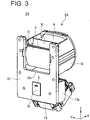
- FIG. 3 is a perspective view of the lamp unit 2A, as seen from the rear side, with a reflector unit 16 removed.
- FIG. 4 is a cross-sectional view illustrating a configuration of the lamp unit 2A.
- FIG. 5 is a schematic diagram illustrating an optical path of light in the lamp unit 2A.
- the present invention can be applied to a variable light distribution headlight (ADB) configured to variably control light distribution patterns to be projected toward the front of a vehicle body as a vehicular headlight (headlamp) mounted on the front of the vehicle body.
- ADB variable light distribution headlight
- the vehicular lamp 1A includes the lamp unit 2A.
- the vehicular lamp 1A has a structure in which the lamp unit 2A is disposed inside a lamp body composed of a housing having an open front surface (not shown) and a transparent lens cover configured to cover the opening of the housing.
- the lamp unit 2A of the present exemplary embodiment generally may include a light source 3, a projecting optical system 4, a liquid crystal element 5, a condensing optical system 6, a polarizing beam splitter 7, a reflecting optical system 8, a polarization rotation element 9, a first polarizing plate 10, and a second polarizing plate 11.
- the light source 3 can emit unpolarized light L.
- the light source 3 may adopt a light-emitting element such as a light-emitting diode (LED) that emits white light, for example.
- LEDs of a high output (high luminance) type for vehicle lighting may preferably be used.
- the light source 3 can emit the light L emitted by the LED radially toward the rear side (-X axis direction) in a state in which the LED is mounted on one surface (in this exemplary embodiment, the rear surface) of a mounting board 12.
- a light-emitting element such as a laser diode (LD) may be used other than the above-described LED.
- a light source other than the above-described light-emitting element may be used.
- the number of light-emitting elements is not limited to one, and may be two or more.
- the mounting board 12 may be formed of a rectangular printed wiring board on at least one surface of which wiring (not shown) electrically connected to the above-mentioned LED (light source 3) is provided.
- the light source 3 includes a plurality of LEDs
- the plurality of LEDs may be mounted in a state in which they are arranged at equal intervals in the widthwise direction of the mounting board 12.
- the mounting board 12 on which the above-mentioned LED (light source 3) has been mounted and a circuit board on which an LED driving circuit for driving the LED (light source 3) is provided are separately arranged, and the mounting board and the circuit board are electrically connected to each other via wiring cords called harnesses. As a result, the LED driving circuit is protected from the heat generated by the LED (light source 3).
- the lamp unit 2A of the present exemplary embodiment includes a heat sink 13 in which a plurality of heat dissipation fins 13a for dissipating heat generated by the light source 3 are provided on the front surface side, and a cooling fan 14 disposed on the front surface side of the heat sink 13.
- the mounting board 12 is attached to a position opposite to the heat dissipation fins 13a on the rear surface side of the heat sink 13 by screwing or the like.
- the mounting board 12 may be attached to the heat sink 13 via a heat transfer member such as a heat conduction grease.
- the heat sink 13 is formed, at least partially or entirely, of a metal material such as aluminum, copper, or the like having high thermal conductivity, a resin material, a composite material of these, or the like.
- the cooling fan 14 blows air toward the heat dissipation fins 13a. As a result, it is possible to efficiently dissipate heat transferred from the light source 3 to the heat sink 13 to the outside.
- the projection optical system 4 is composed of at least one or a plurality of (one in this exemplary embodiment) lenses (hereinafter, referred to as a projection lens 4) configured to project the light L emitted from the light source 3 toward the front (+X axis direction).
- the projection lens 4 is disposed on the front side of the liquid crystal element 5 while being held by a holder 15.
- the holder 15 is attached to the front side of the heat sink 13 positioned above the heat dissipation fins 13a by screwing or the like.
- the heat sink 13 is provided with a notched portion 13b which is notched so as to face the projection lens 4 (see FIGS. 3 and 4 ).
- the liquid crystal element 5 is formed of a light transmissive liquid crystal panel (LCD).
- the projection lens 4 has a rear focal point fp, and the liquid crystal element 5 is arranged in coincidence with the rear focal point fp of the projection lens 4. That is, the liquid crystal element 5 is located at or near the rear focal point fp of the projection lens 4.
- the liquid crystal element 5 is held inside the holder 15.
- the drive voltage applied between the electrodes is controlled by a liquid crystal drive circuit (not shown), so that the liquid crystal element 5 controls the image (light distribution pattern) of first light L1 and second light L2 projected by the projection lens 4 while modulating the light (the first light L1 and the second light L2 to be described later) passing therethrough.
- the liquid crystal element 5 may be of a segment type in which light modulation is switched by controlling a drive voltage applied between electrodes in one segment, or may be of a dot matrix type in which light modulation is switched in an arbitrary area by controlling a drive voltage applied between electrodes of dots (pixels) arranged in a matrix.
- the condensing optical system 6 includes a first reflector (hereinafter, called as the first reflector 6) configured to condense the light L emitted from the light source 3 toward the liquid crystal element 5.
- the first reflector 6 has a concave elliptical reflecting surface 6a formed such that its cross-sectional shape describes an elliptical line having two focal points fe1 and fe2.
- the first focal point fe1 of the elliptical reflecting surface 6a coincides with the position of the light source 3.
- the first reflector 6 reflects the light L from the light source 3 disposed in coincidence with the first focal point fe1 of the elliptical reflection surface 6a while focusing the light L toward the second focal point fe2 of the elliptical reflection surface 6a.
- the polarizing beam splitter 7 separates the light L emitted from the light source 3 into the first light L1 containing one polarization component (e.g., P-polarization component) and the second light L2 containing the other polarization component (e.g., S-polarization component).
- the polarizing beam splitter 7 is disposed in an optical path between the condensing optical system (the first reflector) 6 and the reflecting optical system (second reflector, which will be described later) 8.
- the polarizing beam splitter 7 for example, a wire grid method, an optical multilayer film, or the like can be used.
- the polarizing beam splitter 7 is not limited to those of a plate type having a flat plate shape, and may be those of a cube type in which two rectangular prisms are combined.
- the polarizing beam splitter 7 transmits the first light L1 of the light L emitted from the light source 3 toward the upper side (+Z axis direction) while reflecting the second light L2 toward the front side (+X axis direction).
- the polarizing beam splitter 7 reflects the second light L2 so that the condensing point C2 of the second light L2 coincides with the rear focal point fp of the projection lens 4.
- the reflecting optical system 8 is constituted by a second reflector (hereinafter referred to as a second reflector 8) that reflects the first light L1 toward the liquid crystal element 5.
- the second reflector 8 has a convex hyperbolic reflecting surface 8a whose cross-sectional shape is formed to draw a hyperbola having two focal points fh1 and fh2.
- the hyperbolic reflecting surface 8a has its first focal point fh1 in coincidence with the second focal point fe2 of the elliptical reflecting surface 6a, and its second focal point fh2 in coincidence with the rear focal point fp of the projection lens 4.
- the second reflector 8 is configured to reflect the first light L1 by the hyperbolic reflecting surface 8a so that the condensing point C1 of the first light L1 coincides with the rear focal point fp of the projection lens 4.
- the lamp unit 2A of the present exemplary embodiment includes a reflector unit 16 in which the first reflector 6 and the second reflector 8 are integrally formed.
- the reflector unit 16 is formed of, for example, a resin material.
- the elliptical reflection surface 6a and the hyperbolic reflection surface 8a are formed of a metallic reflection film having a high reflectance, for example, a metal alloy deposited by evaporation of an aluminum alloy or the like.
- the reflector unit 16 is attached to the rear surface of the heat sink 13 by screwing or the like while the polarizing beam splitter 7 is held inside the reflector unit 16.
- the polarization rotation element 9 is composed of a half wavelength ( ⁇ /2) plate disposed in an optical path between the polarizing beam splitter 7 and the liquid crystal element 5.
- the polarization rotation element 9 is attached to the front surface of the reflector unit 16 described above.
- the polarization rotation element 9 rotates the polarization direction of one of the first light L1 and the second light L2 (in the present exemplary embodiment, the first light L1), and transmits the light toward the liquid crystal element 5 in a state in which the polarization direction of the one light (first light L1) is made coincide with the polarization direction of the other light (in the present exemplary embodiment, the second light L2).
- the ⁇ /2 plate (polarization rotation element 9) is disposed in the optical path of the first light L1 between the second reflector 8 and the liquid crystal element 5.
- the ⁇ /2 plate converts the polarization direction of the first light L1 from P-polarized light to S-polarized light. This makes it possible to match the polarization directions of the first light L1 and the second light L2 with each other.
- a ⁇ /2 plate (polarization rotation element 9) only needs to be disposed in the optical path of the second light L2 between the polarizing beam splitter 7 and the liquid crystal element 5.
- an optical element configured to rotate the polarization direction such as a Faraday element or a liquid crystal element can be used other than the above-mentioned retardation plate such as a ⁇ /2 plate.
- the first polarizing plate 10 is disposed in an optical path between the liquid crystal element 5 and the projection lens 4. In the lamp unit 2A of the present exemplary embodiment, the first polarizing plate 10 is held inside the holder 15.
- the first polarizing plate 10 transmits light of a specific polarization component out of the first light L1 and the second light L2 having been modulated by the liquid crystal element 5. That is, the first polarizing plate 10 transmits the light of the polarization component corresponding to the light distribution pattern of the light controlled by the liquid crystal element 5, and blocks the light of the other polarization components. By doing so, the first light L1 and the second light L2 having been modulated by the liquid crystal element 5 can be selectively caused to transmit in accordance with the light distribution pattern of the light controlled by the liquid crystal element 5.
- the second polarizing plate 11 is disposed in the optical paths of the first light L1 and the second light L2 that enter the liquid crystal element 5.
- the second polarizing plate 11 is held inside the holder 15.
- the second polarizing plate 11 transmits the light of the polarization component (S-polarized light in this exemplary embodiment) having the same polarization direction out of the first light L1 and the second light L2, and blocks the light of the other polarization components.
- the degree of polarization of the first light L1 and the second light L2 that enter the liquid crystal element 5 can be improved.
- the second polarizing plate 11 can be omitted in some cases.
- first polarizing plate 10 and the second polarizing plate 11 described above generate heat by blocking (absorbing) light, it is preferable that they are disposed separately from the liquid crystal element 5.
- the control circuit unit calculates the region to be shielded by judging the surrounding information of a preceding vehicle, an oncoming vehicle, or the like using images obtained from cameras provided in the vehicle body and information of various sensors provided in the vehicle body, and transmits the information of the region to be shielded to the liquid crystal drive circuit as a control signal.
- the liquid crystal driving circuit controls the image (light distribution pattern) of the light L1 and light L2 projected by the projection lens 4 while controlling the driving of the liquid crystal element 5 on the basis of the control signal from the control circuit unit. As a result, it is possible to variably control the light distribution patterns of the light L1 and light L2 projected from the projection lens 4 toward the front of the vehicle body.
- the vehicular lamp 1A of the present exemplary embodiment serving as ADB can enlarge the driver's field of front vision at night by recognizing the surrounding conditions of a preceding vehicle, an oncoming vehicle, and the like with the in-vehicle cameras and the like, and shielding light that may give glare to the preceding vehicle, the oncoming vehicle, and the like.
- the light L emitted from the light source 3 can be reflected while being condensed toward the liquid crystal element 5 by the first reflector 6 (elliptical reflecting surface 6a). Furthermore, the light L emitted from the light source 3 can be separated into the first light L1 including one polarization component having transmitted through the polarizing beam splitter 7 and the second light L2 including the other polarization component reflected by the polarizing beam splitter 7.
- the first light L1 is reflected toward the liquid crystal element 5 by the second reflector 8 (hyperbolic reflective surface 8a).
- the second light L2 is reflected toward the liquid crystal element 5 by the polarizing beam splitter 7.
- the first light L1 and the second light L2 enter the liquid crystal element 5 in a state in which the polarization directions of the first light L1 and the second light L2 are matched (in coincidence) with each other by the polarizing rotation element 9 and the second polarizing plate 11.
- the first reflector 6 reflects the light L from the light source 3 disposed in coincidence with the first focal point fe1 of the elliptical reflection surface 6a while condensing the light L toward the second focal point fe2 of the elliptical reflection surface 6a.
- the second reflector 8 since the second reflector 8 has the hyperbolic reflecting surface 8a with the first focal point fh1 in coincidence with the second focal point fe2 of the elliptical reflecting surface 6a, and the second focal point fh2 in coincidence with the rear focal point fp of the projection lens 4, the second reflector 8 can reflect the first light L1 while condensing toward the second focal point fh2 of the hyperbolic reflecting surface 8a.
- the second reflector 8 reflects the first light L1 so that the condensing point C1 of the first light L1 coincides with the rear focal point fp of the projection lens 4.
- the polarizing beam splitter 7 reflects the second light L2 so that the condensing point C2 of the second light L2 coincides with the rear focal point fp of the projection lens 4.
- the first light L1 and the second light L2 are condensed at the shared condensing points C1 and C2, i.e., the rear focal point fp of the projector lens 4. Accordingly, without increasing the number of the light sources 3, the light of the two polarization components separated by the polarizing beam splitter 7, i.e., the first light L1 and the second light L2, can be condensed on one liquid crystal element 5, and the utilization efficiency of the light L emitted from the light source 3 can be increased.
- the liquid crystal element 5 is located at the shared condensing points C1 and C2, i.e., the rear focal point fp of the projection lens 4.
- the polarization directions of the first light L1 and the second light L2 that enter the liquid crystal element 5 can be made coincide with each other more properly.
- the luminous intensity of the light distribution patterns of the light L1 and light L2 projected from the projection lens 4 toward the front of the vehicle body can be increased.
- visibility in front of the vehicle body, particularly in a farther area can be enhanced, and safety can be further improved.
- the lamp unit 2A of the present exemplary embodiment there is no need to separately use liquid crystal elements 5, projection lenses 4, and the like for the respective two polarization components separated by the polarizing beam splitters 7, rather these components can be commonly used.
- the number of components constituting the lamp unit 2A can be reduced and the structure can be simplified, and thus the lamp unit 2A can be further downsized and lightened.
- the provision of the above-described lamp unit 2A can improve the utilization efficiency of the light emitted from the light source 3, and the reduced number of components and simplified structure can further downsize and lighten the entire lamp unit 2A.
- FIG. 6 is a perspective view of a lamp unit 2B of the vehicular lamp 1B, as seen from the front side.
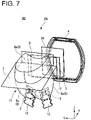
- FIG. 7 is a perspective view of the lamp unit 2B, as seen from the rear side.
- FIG. 8 is a front view illustrating the configuration of the lamp unit 2B.
- FIG. 9 is a rear view illustrating the configuration of the lamp unit 2B.
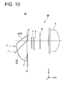
- FIG. 10 is a side view illustrating the configuration of the lamp unit 2B.
- FIG. 11 is a schematic diagram illustrating an optical path of light in the lamp unit 2B.
- the same reference numerals are assigned to the same parts as those of the vehicular lamp 1A (lamp unit 2A) in the drawings, and the description thereof will be omitted.
- the vehicular lamp 1B of the present exemplary embodiment includes the lamp unit 2B.
- the vehicular lamp 1B has a structure in which the lamp unit 2B is disposed inside a lamp body composed of a housing having an opening at its front surface (not shown) and a transparent lens cover covering the opening of the housing.
- the lamp unit 2B of the present exemplary embodiment includes a plurality of (two in the present exemplary embodiment) light sources 3 and a plurality of (two in the present exemplary embodiment) first reflectors 6 corresponding to the plurality of light sources 3, respectively.
- the lamp unit 2B of the present exemplary embodiment includes a reflector unit 17 in which the plurality of first reflectors 6, the polarizing beam splitter 7, and the second reflector 8 are integrally formed.
- the lamp unit 2B generally includes the projection lens (projection optical system) 4, the liquid crystal element 5, the polarization rotation element 9, the first polarizing plate 10, and the second polarizing plate 11 similarly to the lamp unit 2A described above.
- a plurality of (two in this embodiment) mounting boards 12 on which the light sources 3 are mounted are attached to the above-described heat sinks 13 (not shown in FIGS. 6 to 11 ) on the rear surface side thereof by screwing or the like.
- the plurality of first reflectors 6 reflect the light L from the respective light sources 3 arranged in coincidence with the first focal point fe1 of each of the elliptical reflective surfaces 6a while being condensed toward the second focal point fe2 of each of the elliptical reflective surfaces 6a.
- the second focal points fe2 of the elliptical reflecting surfaces 6a of the first reflectors 6 are located at the same position in terms of optical design. Therefore, the plurality of first reflectors 6 condense the light L emitted from the plurality of light sources 3 toward the mutually coincident focal point, i.e., the second focal point fe2.
- the second reflector 8 has the hyperbolic reflecting surface 8a with the first focal point fh1 that coincides with the shared second focal point fe2 of the elliptical reflecting surfaces 6a of the respective first reflectors 6, and the second focal point fh2 that coincides with the rear focal point fp of the projecting lens 4, so that the first light L1 is reflected while being condensed toward the second focal point fh2 of the hyperbolic reflecting surface 8a.
- the second reflector 8 reflects the first light L1 so that the condensing point C1 of the first light L1 coincides with the rear focal point fp of the projection lens 4.
- the polarizing beam splitter 7 reflects the second light L2 so that the condensing point C2 of the second light L2 coincides with the rear focal point fp of the projection lens 4.
- the first light L1 and the second light L2 separated by the polarizing beam splitter 7 out of the light L emitted from the plurality of light sources 3 described above are condensed at the mutually shared condensing points C1 and C2 (the rear focal point fp of the projection lens 4).
- the light of the two polarization components separated by the polarizing beam splitter 7, i.e., the first light L1 and the second light L2 can be condensed on the single liquid crystal element 5, and the utilization efficiency of the light L emitted from the plurality of light sources 3 can be increased.
- the liquid crystal element 5 is located at the shared condensing points C1 and C2, i.e., the rear focal point fp of the projection lens 4.
- the polarization directions of the first light L1 and the second light L2 that enter the liquid crystal element 5 can be made coincide with each other more properly.
- the lamp unit 2B of the present exemplary embodiment even when a plurality of light sources 3 are used, the luminous intensity of the light distribution patterns of the light L1 and light L2 projected from the projection lens 4 toward the front of the vehicle body can be increased. As a result, visibility in front of the vehicle body, particularly in the farther area, can be enhanced, and safety can be further improved.
- the lamp unit 2B of the present exemplary embodiment when the plurality of light sources 3 are used, components such as the polarizing beam splitter 7, the second reflector 8, the liquid crystal element 5, and the projection lens 4 can be commonly used (shared). Thus, even when a plurality of light sources 3 are used, the number of components constituting the lamp unit 2B can be reduced and the structure can be simplified, and the lamp unit 2B can be further reduced in size and weight.
- the provision of the above-described lamp unit 2B can improve the utilization efficiency of the light emitted from the plurality of light sources 3, and the reduced number of components and simplified structure can further downsize and lighten the lamp unit 2B.
- FIG. 12 is a schematic view illustrating the configuration of the lamp unit 1C included in the vehicular lamp 1C and the optical path of the light.
- the same reference numerals are assigned to the same parts as those of the vehicular lamp 1A (lamp unit 2A) in the drawings, and the description thereof will be omitted.
- the vehicular lamp 1C of the present exemplary embodiment includes the lamp unit 2C.
- the vehicular lamp 1C has a structure in which the lamp unit 2C is disposed inside a lamp body composed of a housing having an opening at its front surface (not shown) and a transparent lens cover covering the opening of the housing.
- the lamp unit 2C of the present exemplary embodiment includes, as a condensing optical system, a condenser lens 18 instead of the first reflector 6.
- the condenser lens 18 is composed of at least one or a plurality of lenses (in this embodiment, a single lens) configured to condense the light L emitted from the light source 3 toward the liquid crystal element 5.
- the condenser lens 18 is disposed in the optical path between the light source 3 and the polarizing beam splitter 7.
- the other components and configuration are the same as those of the lamp unit 2A.
- the light L emitted from the light source 3 is condensed toward the liquid crystal element 5 by the condenser lens 18.
- the light L emitted from the light source 3 is separated into first light L1 including one polarization component having transmitted through the polarizing beam splitter 7 and second light L2 including the other polarization component reflected by the polarizing beam splitter 7.
- the first light L1 is reflected toward the liquid crystal element 5 by the second reflector 8 (hyperbolic reflective surface 8a).
- the second light L2 is reflected toward the liquid crystal element 5 by the polarizing beam splitter 7. Furthermore, the first light L1 and the second light L2 enter the liquid crystal element 5 in a state in which the polarization directions of the first light L1 and the second light L2 are matched (in coincidence) with each other by the polarizing rotation element 9 and the second polarizing plate 11.
- the condenser lens 18 has a front focal point fc so as to condense the light L, emitted from the light source 3, toward the front focal point fc.
- the second reflector 8 since the second reflector 8 has the hyperbolic reflecting surface 8a with the first focal point fh1 in coincidence with the front focal point fc of the condenser lens 18, and the second focal point fh2 in coincidence with the rear focal point fp of the projection lens 4, the second reflector 8 can reflect the first light L1 while condensing toward the second focal point fh2 of the hyperbolic reflecting surface 8a.
- the second reflector 8 reflects the first light L1 so that the condensing point C1 of the first light L1 coincides with the rear focal point fp of the projection lens 4.
- the polarizing beam splitter 7 reflects the second light L2 so that the condensing point C2 of the second light L2 coincides with the rear focal point fp of the projection lens 4.
- the first light L1 and the second light L2 are condensed at the shared condensing points C1 and C2, i.e., the rear focal point fp of the projector lens 4. Accordingly, without increasing the number of the light sources 3, the light of the two polarization components separated by the polarizing beam splitter 7, i.e., the first light L1 and the second light L2, can be condensed on one liquid crystal element 5, and the utilization efficiency of the light L emitted from the light source 3 can be increased.
- the liquid crystal element 5 is located at the shared condensing points C1 and C2, i.e., the rear focal point fp of the projection lens 4.
- the polarization directions of the first light L1 and the second light L2 that enter the liquid crystal element 5 can be made coincide with each other further more.
- the luminous intensity of the light distribution patterns of the light L1 and light L2 projected from the projection lens 4 toward the front of the vehicle body can be increased.
- visibility in front of the vehicle body, particularly in the farther area can be enhanced, and safety can be further improved.
- the lamp unit 2C of the present exemplary embodiment there is no need to separately use liquid crystal element 5, projection lens 4, and the like for the respective two polarization components separated by the polarizing beam splitters 7, rather these components can be commonly used.
- the number of components constituting the lamp unit 2C can be reduced and the structure can be simplified, and thus the lamp unit 2C can be further downsized and lightened.
- the provision of the above-described lamp unit 2C can improve the utilization efficiency of the light emitted from the light source 3, and the reduced number of components and simplified structure can further downsize and lighten the lamp unit 2C.
- the polarizing beam splitter 7 is held inside the reflector units 16 and 17 in which the first reflector 6 and the second reflector 8 are integrally formed, but a light guide unit in which the first reflector 6 (elliptical reflection surface 6a), the second reflector 8 (hyperbolic reflection surface 8a), and the polarizing beam splitter 7 are integrally formed may be used.
- the light guide unit has a configuration in which the polarizing beam splitter 7 is disposed on the abutting surface of a light guiding body, and the elliptical reflection surface 6a and the hyperbolic reflection surface 8a are disposed on the outer peripheral surface of the light guiding body.
- the light guide unit the light L emitted from the light source 3 is guided inside the light guiding body, and the light of the two polarization components (the first light L1 and the second light L2) separated by the polarizing beam splitter 7 is reflected by the ellipsoidal reflection surface 6a and the hyperbolic reflection surface 8a.
- the same (similar) configuration as that of the first reflector 6 (elliptical reflection surface 6a), the second reflector 8 (hyperbolic reflection surface 8a), and the polarizing beam splitter 7 can be obtained.
- variable light distribution headlamp ADB
- present invention may also be applied to a variable light distribution headlamp (AFS: Adaptive Front-Lighting System) which ensures visibility in the vehicle traveling direction by controlling the liquid crystal element in accordance with the steering angle (turning angle) and the speed (vehicle speed) of the vehicle body traveling while turning so as to enlarge the illumination range of the passing beams in the vehicle traveling direction.
- ADB variable light distribution headlamp
- AFS Adaptive Front-Lighting System
- the present invention can also be applied to a bi-functional type vehicular lamp capable of switching a low-beam light distribution pattern including a cut-off line at the upper end as a passing beam (low beam) and a high-beam light distribution pattern positioned above the low-beam light distribution pattern as a traveling beam (high beam) by one lamp unit.
Landscapes
- Physics & Mathematics (AREA)
- Engineering & Computer Science (AREA)
- General Engineering & Computer Science (AREA)
- Nonlinear Science (AREA)
- Chemical & Material Sciences (AREA)
- Crystallography & Structural Chemistry (AREA)
- Optics & Photonics (AREA)
- General Physics & Mathematics (AREA)
- Mathematical Physics (AREA)
- Microelectronics & Electronic Packaging (AREA)
- Non-Portable Lighting Devices Or Systems Thereof (AREA)
- Fastening Of Light Sources Or Lamp Holders (AREA)
- Liquid Crystal (AREA)
Applications Claiming Priority (1)
| Application Number | Priority Date | Filing Date | Title |
|---|---|---|---|
| JP2018135041A JP7171283B2 (ja) | 2018-07-18 | 2018-07-18 | 車両用灯具 |
Publications (2)
| Publication Number | Publication Date |
|---|---|
| EP3597988A1 EP3597988A1 (en) | 2020-01-22 |
| EP3597988B1 true EP3597988B1 (en) | 2022-06-15 |
Family
ID=67437951
Family Applications (1)
| Application Number | Title | Priority Date | Filing Date |
|---|---|---|---|
| EP19186940.3A Active EP3597988B1 (en) | 2018-07-18 | 2019-07-18 | Vehicular lamp |
Country Status (4)
| Country | Link |
|---|---|
| US (1) | US10808905B2 (ja) |
| EP (1) | EP3597988B1 (ja) |
| JP (1) | JP7171283B2 (ja) |
| CN (1) | CN110736071B (ja) |
Families Citing this family (4)
| Publication number | Priority date | Publication date | Assignee | Title |
|---|---|---|---|---|
| JP2021150182A (ja) * | 2020-03-19 | 2021-09-27 | スタンレー電気株式会社 | ランプユニット、車両用灯具システム |
| JP7394696B2 (ja) * | 2020-04-24 | 2023-12-08 | スタンレー電気株式会社 | 車両用灯具システム |
| JP2022068967A (ja) * | 2020-10-23 | 2022-05-11 | スタンレー電気株式会社 | 車両用灯具及び光学素子 |
| JP2022179096A (ja) * | 2021-05-21 | 2022-12-02 | スタンレー電気株式会社 | 車両用灯具 |
Family Cites Families (23)
| Publication number | Priority date | Publication date | Assignee | Title |
|---|---|---|---|---|
| JPH01244934A (ja) * | 1988-03-28 | 1989-09-29 | Nissan Motor Co Ltd | 車両用前照灯装置 |
| JP3336664B2 (ja) * | 1993-03-10 | 2002-10-21 | セイコーエプソン株式会社 | 投写型表示装置 |
| JP2003297116A (ja) * | 2002-04-05 | 2003-10-17 | Honda Motor Co Ltd | 投光装置 |
| JP2006189781A (ja) * | 2004-12-08 | 2006-07-20 | Nitto Denko Corp | 液晶パネル及び液晶表示装置 |
| JP5448615B2 (ja) * | 2009-07-14 | 2014-03-19 | 株式会社小糸製作所 | 車両用前照灯 |
| JP5436318B2 (ja) * | 2010-04-26 | 2014-03-05 | 株式会社小糸製作所 | 車両用前照灯および車両用前照灯システム |
| JP2011249184A (ja) * | 2010-05-28 | 2011-12-08 | Koito Mfg Co Ltd | 車両用前照灯 |
| JP2012069458A (ja) * | 2010-09-27 | 2012-04-05 | Stanley Electric Co Ltd | 車両用灯具 |
| DE102010062465B4 (de) * | 2010-12-06 | 2021-02-04 | Coretronic Corporation | Leuchtvorrichtung |
| CN104344299A (zh) * | 2013-07-23 | 2015-02-11 | 鸿富锦精密工业(深圳)有限公司 | 车前灯灯具模组 |
| CN105745485B (zh) * | 2013-11-18 | 2019-04-02 | 麦克赛尔株式会社 | 固体光源装置和使用它的车辆用灯具、影像显示装置及固体光源装置的驱动方法 |
| DE102013113807A1 (de) | 2013-12-11 | 2015-06-11 | Hella Kgaa Hueck & Co. | Beleuchtungseinrichtung für ein Kraftfahrzeug |
| WO2015185469A1 (en) * | 2014-06-05 | 2015-12-10 | Koninklijke Philips N.V. | Luminescence concentrator with increased efficiency |
| DE102014113700A1 (de) * | 2014-09-23 | 2016-03-24 | Hella Kgaa Hueck & Co. | Scheinwerfer für Fahrzeuge |
| EP3216650A4 (en) * | 2014-11-07 | 2018-06-13 | Dai Nippon Printing Co., Ltd. | Lighting device |
| JP6564568B2 (ja) * | 2014-12-11 | 2019-08-21 | スタンレー電気株式会社 | 車両用前照灯ユニット、車両用前照灯システム |
| AT517306B1 (de) * | 2015-06-10 | 2017-08-15 | Zkw Group Gmbh | Scheinwerfer für Kraftfahrzeuge |
| DE102015115348A1 (de) * | 2015-09-11 | 2017-03-16 | Hella Kgaa Hueck & Co. | Beleuchtungseinrichtung für ein Kraftfahrzeug |
| DE102016109530A1 (de) | 2016-05-24 | 2017-11-30 | Dr. Ing. H.C. F. Porsche Aktiengesellschaft | Kraftfahrzeug-Scheinwerfer |
| JP2018004673A (ja) * | 2016-06-27 | 2018-01-11 | 日本精機株式会社 | 照明装置 |
| CN109937321B (zh) * | 2017-01-25 | 2021-09-17 | 麦克赛尔株式会社 | 前灯装置 |
| JP6865775B2 (ja) * | 2017-01-27 | 2021-04-28 | マクセル株式会社 | ヘッドライト装置 |
| JP6952541B2 (ja) * | 2017-09-11 | 2021-10-20 | スタンレー電気株式会社 | 車両用前照灯 |
-
2018
- 2018-07-18 JP JP2018135041A patent/JP7171283B2/ja active Active
-
2019
- 2019-07-17 US US16/513,731 patent/US10808905B2/en active Active
- 2019-07-18 CN CN201910649048.8A patent/CN110736071B/zh active Active
- 2019-07-18 EP EP19186940.3A patent/EP3597988B1/en active Active
Also Published As
| Publication number | Publication date |
|---|---|
| JP7171283B2 (ja) | 2022-11-15 |
| CN110736071A (zh) | 2020-01-31 |
| CN110736071B (zh) | 2023-11-14 |
| US20200025350A1 (en) | 2020-01-23 |
| EP3597988A1 (en) | 2020-01-22 |
| US10808905B2 (en) | 2020-10-20 |
| JP2020013697A (ja) | 2020-01-23 |
Similar Documents
| Publication | Publication Date | Title |
|---|---|---|
| EP3597988B1 (en) | Vehicular lamp | |
| EP2772682B1 (en) | Vehicle lamp and vehicle lighting system | |
| US7131759B2 (en) | Vehicular lamp and light source module | |
| US7165871B2 (en) | Lamp | |
| EP2187115B1 (en) | Vehicular lamp | |
| US10823360B2 (en) | Headlight device and bending headlight module thereof | |
| JP5468754B2 (ja) | 自動車ヘッドライト用のプロジェクションモジュール | |
| US9506615B2 (en) | Motor vehicle headlamp having a multi-function projection module | |
| JP6952541B2 (ja) | 車両用前照灯 | |
| CN105465713B (zh) | 用于机动车辆的发光照明和/或信号指示模块 | |
| US9447941B2 (en) | Lamp for vehicle | |
| JP4735424B2 (ja) | 車両用灯具 | |
| EP3537032B1 (en) | Lighting tool for vehicle | |
| JP7108359B2 (ja) | 車両用灯具 | |
| CN113757618B (zh) | 车辆用灯具 | |
| WO2021208536A1 (zh) | 初级光学结构、远光照明装置、防炫目远光灯及车辆 | |
| WO2022244677A1 (ja) | 車両用灯具 | |
| CN110296370B (zh) | 车辆用灯具 | |
| JP4168890B2 (ja) | 車両用灯具 | |
| JP2022127822A (ja) | 車両用灯具 | |
| JP7382199B2 (ja) | 車両用前照灯 | |
| JP7423371B2 (ja) | 車両用灯具 | |
| JP2022162292A (ja) | 車両用灯具 |
Legal Events
| Date | Code | Title | Description |
|---|---|---|---|
| PUAI | Public reference made under article 153(3) epc to a published international application that has entered the european phase |
Free format text: ORIGINAL CODE: 0009012 |
|
| STAA | Information on the status of an ep patent application or granted ep patent |
Free format text: STATUS: THE APPLICATION HAS BEEN PUBLISHED |
|
| AK | Designated contracting states |
Kind code of ref document: A1 Designated state(s): AL AT BE BG CH CY CZ DE DK EE ES FI FR GB GR HR HU IE IS IT LI LT LU LV MC MK MT NL NO PL PT RO RS SE SI SK SM TR |
|
| AX | Request for extension of the european patent |
Extension state: BA ME |
|
| STAA | Information on the status of an ep patent application or granted ep patent |
Free format text: STATUS: REQUEST FOR EXAMINATION WAS MADE |
|
| 17P | Request for examination filed |
Effective date: 20200722 |
|
| RBV | Designated contracting states (corrected) |
Designated state(s): AL AT BE BG CH CY CZ DE DK EE ES FI FR GB GR HR HU IE IS IT LI LT LU LV MC MK MT NL NO PL PT RO RS SE SI SK SM TR |
|
| GRAP | Despatch of communication of intention to grant a patent |
Free format text: ORIGINAL CODE: EPIDOSNIGR1 |
|
| STAA | Information on the status of an ep patent application or granted ep patent |
Free format text: STATUS: GRANT OF PATENT IS INTENDED |
|
| INTG | Intention to grant announced |
Effective date: 20220103 |
|
| GRAS | Grant fee paid |
Free format text: ORIGINAL CODE: EPIDOSNIGR3 |
|
| GRAA | (expected) grant |
Free format text: ORIGINAL CODE: 0009210 |
|
| STAA | Information on the status of an ep patent application or granted ep patent |
Free format text: STATUS: THE PATENT HAS BEEN GRANTED |
|
| AK | Designated contracting states |
Kind code of ref document: B1 Designated state(s): AL AT BE BG CH CY CZ DE DK EE ES FI FR GB GR HR HU IE IS IT LI LT LU LV MC MK MT NL NO PL PT RO RS SE SI SK SM TR |
|
| REG | Reference to a national code |
Ref country code: CH Ref legal event code: EP Ref country code: GB Ref legal event code: FG4D |
|
| REG | Reference to a national code |
Ref country code: IE Ref legal event code: FG4D |
|
| REG | Reference to a national code |
Ref country code: DE Ref legal event code: R096 Ref document number: 602019015826 Country of ref document: DE |
|
| REG | Reference to a national code |
Ref country code: AT Ref legal event code: REF Ref document number: 1498598 Country of ref document: AT Kind code of ref document: T Effective date: 20220715 |
|
| REG | Reference to a national code |
Ref country code: LT Ref legal event code: MG9D |
|
| REG | Reference to a national code |
Ref country code: NL Ref legal event code: MP Effective date: 20220615 |
|
| PG25 | Lapsed in a contracting state [announced via postgrant information from national office to epo] |
Ref country code: SE Free format text: LAPSE BECAUSE OF FAILURE TO SUBMIT A TRANSLATION OF THE DESCRIPTION OR TO PAY THE FEE WITHIN THE PRESCRIBED TIME-LIMIT Effective date: 20220615 Ref country code: NO Free format text: LAPSE BECAUSE OF FAILURE TO SUBMIT A TRANSLATION OF THE DESCRIPTION OR TO PAY THE FEE WITHIN THE PRESCRIBED TIME-LIMIT Effective date: 20220915 Ref country code: LT Free format text: LAPSE BECAUSE OF FAILURE TO SUBMIT A TRANSLATION OF THE DESCRIPTION OR TO PAY THE FEE WITHIN THE PRESCRIBED TIME-LIMIT Effective date: 20220615 Ref country code: HR Free format text: LAPSE BECAUSE OF FAILURE TO SUBMIT A TRANSLATION OF THE DESCRIPTION OR TO PAY THE FEE WITHIN THE PRESCRIBED TIME-LIMIT Effective date: 20220615 Ref country code: GR Free format text: LAPSE BECAUSE OF FAILURE TO SUBMIT A TRANSLATION OF THE DESCRIPTION OR TO PAY THE FEE WITHIN THE PRESCRIBED TIME-LIMIT Effective date: 20220916 Ref country code: FI Free format text: LAPSE BECAUSE OF FAILURE TO SUBMIT A TRANSLATION OF THE DESCRIPTION OR TO PAY THE FEE WITHIN THE PRESCRIBED TIME-LIMIT Effective date: 20220615 Ref country code: BG Free format text: LAPSE BECAUSE OF FAILURE TO SUBMIT A TRANSLATION OF THE DESCRIPTION OR TO PAY THE FEE WITHIN THE PRESCRIBED TIME-LIMIT Effective date: 20220915 |
|
| REG | Reference to a national code |
Ref country code: AT Ref legal event code: MK05 Ref document number: 1498598 Country of ref document: AT Kind code of ref document: T Effective date: 20220615 |
|
| PG25 | Lapsed in a contracting state [announced via postgrant information from national office to epo] |
Ref country code: RS Free format text: LAPSE BECAUSE OF FAILURE TO SUBMIT A TRANSLATION OF THE DESCRIPTION OR TO PAY THE FEE WITHIN THE PRESCRIBED TIME-LIMIT Effective date: 20220615 Ref country code: LV Free format text: LAPSE BECAUSE OF FAILURE TO SUBMIT A TRANSLATION OF THE DESCRIPTION OR TO PAY THE FEE WITHIN THE PRESCRIBED TIME-LIMIT Effective date: 20220615 |
|
| PG25 | Lapsed in a contracting state [announced via postgrant information from national office to epo] |
Ref country code: NL Free format text: LAPSE BECAUSE OF FAILURE TO SUBMIT A TRANSLATION OF THE DESCRIPTION OR TO PAY THE FEE WITHIN THE PRESCRIBED TIME-LIMIT Effective date: 20220615 |
|
| PG25 | Lapsed in a contracting state [announced via postgrant information from national office to epo] |
Ref country code: SM Free format text: LAPSE BECAUSE OF FAILURE TO SUBMIT A TRANSLATION OF THE DESCRIPTION OR TO PAY THE FEE WITHIN THE PRESCRIBED TIME-LIMIT Effective date: 20220615 Ref country code: SK Free format text: LAPSE BECAUSE OF FAILURE TO SUBMIT A TRANSLATION OF THE DESCRIPTION OR TO PAY THE FEE WITHIN THE PRESCRIBED TIME-LIMIT Effective date: 20220615 Ref country code: RO Free format text: LAPSE BECAUSE OF FAILURE TO SUBMIT A TRANSLATION OF THE DESCRIPTION OR TO PAY THE FEE WITHIN THE PRESCRIBED TIME-LIMIT Effective date: 20220615 Ref country code: PT Free format text: LAPSE BECAUSE OF FAILURE TO SUBMIT A TRANSLATION OF THE DESCRIPTION OR TO PAY THE FEE WITHIN THE PRESCRIBED TIME-LIMIT Effective date: 20221017 Ref country code: ES Free format text: LAPSE BECAUSE OF FAILURE TO SUBMIT A TRANSLATION OF THE DESCRIPTION OR TO PAY THE FEE WITHIN THE PRESCRIBED TIME-LIMIT Effective date: 20220615 Ref country code: EE Free format text: LAPSE BECAUSE OF FAILURE TO SUBMIT A TRANSLATION OF THE DESCRIPTION OR TO PAY THE FEE WITHIN THE PRESCRIBED TIME-LIMIT Effective date: 20220615 Ref country code: CZ Free format text: LAPSE BECAUSE OF FAILURE TO SUBMIT A TRANSLATION OF THE DESCRIPTION OR TO PAY THE FEE WITHIN THE PRESCRIBED TIME-LIMIT Effective date: 20220615 Ref country code: AT Free format text: LAPSE BECAUSE OF FAILURE TO SUBMIT A TRANSLATION OF THE DESCRIPTION OR TO PAY THE FEE WITHIN THE PRESCRIBED TIME-LIMIT Effective date: 20220615 |
|
| PG25 | Lapsed in a contracting state [announced via postgrant information from national office to epo] |
Ref country code: PL Free format text: LAPSE BECAUSE OF FAILURE TO SUBMIT A TRANSLATION OF THE DESCRIPTION OR TO PAY THE FEE WITHIN THE PRESCRIBED TIME-LIMIT Effective date: 20220615 Ref country code: IS Free format text: LAPSE BECAUSE OF FAILURE TO SUBMIT A TRANSLATION OF THE DESCRIPTION OR TO PAY THE FEE WITHIN THE PRESCRIBED TIME-LIMIT Effective date: 20221015 |
|
| REG | Reference to a national code |
Ref country code: CH Ref legal event code: PL |
|
| REG | Reference to a national code |
Ref country code: DE Ref legal event code: R097 Ref document number: 602019015826 Country of ref document: DE |
|
| REG | Reference to a national code |
Ref country code: BE Ref legal event code: MM Effective date: 20220731 |
|
| PG25 | Lapsed in a contracting state [announced via postgrant information from national office to epo] |
Ref country code: MC Free format text: LAPSE BECAUSE OF FAILURE TO SUBMIT A TRANSLATION OF THE DESCRIPTION OR TO PAY THE FEE WITHIN THE PRESCRIBED TIME-LIMIT Effective date: 20220615 Ref country code: AL Free format text: LAPSE BECAUSE OF FAILURE TO SUBMIT A TRANSLATION OF THE DESCRIPTION OR TO PAY THE FEE WITHIN THE PRESCRIBED TIME-LIMIT Effective date: 20220615 |
|
| PLBE | No opposition filed within time limit |
Free format text: ORIGINAL CODE: 0009261 |
|
| STAA | Information on the status of an ep patent application or granted ep patent |
Free format text: STATUS: NO OPPOSITION FILED WITHIN TIME LIMIT |
|
| PG25 | Lapsed in a contracting state [announced via postgrant information from national office to epo] |
Ref country code: LU Free format text: LAPSE BECAUSE OF NON-PAYMENT OF DUE FEES Effective date: 20220718 Ref country code: LI Free format text: LAPSE BECAUSE OF NON-PAYMENT OF DUE FEES Effective date: 20220731 Ref country code: DK Free format text: LAPSE BECAUSE OF FAILURE TO SUBMIT A TRANSLATION OF THE DESCRIPTION OR TO PAY THE FEE WITHIN THE PRESCRIBED TIME-LIMIT Effective date: 20220615 Ref country code: CH Free format text: LAPSE BECAUSE OF NON-PAYMENT OF DUE FEES Effective date: 20220731 |
|
| 26N | No opposition filed |
Effective date: 20230316 |
|
| PG25 | Lapsed in a contracting state [announced via postgrant information from national office to epo] |
Ref country code: SI Free format text: LAPSE BECAUSE OF FAILURE TO SUBMIT A TRANSLATION OF THE DESCRIPTION OR TO PAY THE FEE WITHIN THE PRESCRIBED TIME-LIMIT Effective date: 20220615 Ref country code: BE Free format text: LAPSE BECAUSE OF NON-PAYMENT OF DUE FEES Effective date: 20220731 |
|
| PG25 | Lapsed in a contracting state [announced via postgrant information from national office to epo] |
Ref country code: IE Free format text: LAPSE BECAUSE OF NON-PAYMENT OF DUE FEES Effective date: 20220718 |
|
| PGFP | Annual fee paid to national office [announced via postgrant information from national office to epo] |
Ref country code: FR Payment date: 20230620 Year of fee payment: 5 |
|
| PGFP | Annual fee paid to national office [announced via postgrant information from national office to epo] |
Ref country code: GB Payment date: 20230601 Year of fee payment: 5 |
|
| PGFP | Annual fee paid to national office [announced via postgrant information from national office to epo] |
Ref country code: DE Payment date: 20230531 Year of fee payment: 5 |
|
| PG25 | Lapsed in a contracting state [announced via postgrant information from national office to epo] |
Ref country code: IT Free format text: LAPSE BECAUSE OF FAILURE TO SUBMIT A TRANSLATION OF THE DESCRIPTION OR TO PAY THE FEE WITHIN THE PRESCRIBED TIME-LIMIT Effective date: 20220615 |
|
| PG25 | Lapsed in a contracting state [announced via postgrant information from national office to epo] |
Ref country code: HU Free format text: LAPSE BECAUSE OF FAILURE TO SUBMIT A TRANSLATION OF THE DESCRIPTION OR TO PAY THE FEE WITHIN THE PRESCRIBED TIME-LIMIT; INVALID AB INITIO Effective date: 20190718 |
|
| PG25 | Lapsed in a contracting state [announced via postgrant information from national office to epo] |
Ref country code: MK Free format text: LAPSE BECAUSE OF FAILURE TO SUBMIT A TRANSLATION OF THE DESCRIPTION OR TO PAY THE FEE WITHIN THE PRESCRIBED TIME-LIMIT Effective date: 20220615 Ref country code: CY Free format text: LAPSE BECAUSE OF FAILURE TO SUBMIT A TRANSLATION OF THE DESCRIPTION OR TO PAY THE FEE WITHIN THE PRESCRIBED TIME-LIMIT Effective date: 20220615 |