EP3597786B1 - Beschichtetes stahlblech - Google Patents
Beschichtetes stahlblech Download PDFInfo
- Publication number
- EP3597786B1 EP3597786B1 EP18767596.2A EP18767596A EP3597786B1 EP 3597786 B1 EP3597786 B1 EP 3597786B1 EP 18767596 A EP18767596 A EP 18767596A EP 3597786 B1 EP3597786 B1 EP 3597786B1
- Authority
- EP
- European Patent Office
- Prior art keywords
- phase
- steel sheet
- coating layer
- coated steel
- granular
- Prior art date
- Legal status (The legal status is an assumption and is not a legal conclusion. Google has not performed a legal analysis and makes no representation as to the accuracy of the status listed.)
- Active
Links
- 229910000831 Steel Inorganic materials 0.000 title claims description 173
- 239000010959 steel Substances 0.000 title claims description 173
- 239000011247 coating layer Substances 0.000 claims description 174
- 229910019743 Mg2Sn Inorganic materials 0.000 claims description 106
- 229910017708 MgZn2 Inorganic materials 0.000 claims description 70
- 239000010410 layer Substances 0.000 claims description 46
- 229910045601 alloy Inorganic materials 0.000 claims description 45
- 239000000956 alloy Substances 0.000 claims description 45
- 230000005496 eutectics Effects 0.000 claims description 43
- 239000000203 mixture Substances 0.000 claims description 30
- 239000000126 substance Substances 0.000 claims description 25
- 239000013078 crystal Substances 0.000 claims description 21
- 229910000765 intermetallic Inorganic materials 0.000 claims description 21
- 229910052725 zinc Inorganic materials 0.000 claims description 20
- 229910018084 Al-Fe Inorganic materials 0.000 claims description 12
- 229910018192 Al—Fe Inorganic materials 0.000 claims description 12
- 229910052804 chromium Inorganic materials 0.000 claims description 11
- 229910052759 nickel Inorganic materials 0.000 claims description 11
- 229910052782 aluminium Inorganic materials 0.000 claims description 10
- 229910052748 manganese Inorganic materials 0.000 claims description 10
- 229910052719 titanium Inorganic materials 0.000 claims description 10
- 229910052802 copper Inorganic materials 0.000 claims description 9
- 229910052758 niobium Inorganic materials 0.000 claims description 9
- 229910052720 vanadium Inorganic materials 0.000 claims description 9
- 239000012535 impurity Substances 0.000 claims description 8
- 229910052787 antimony Inorganic materials 0.000 claims description 7
- 229910052796 boron Inorganic materials 0.000 claims description 7
- 229910052745 lead Inorganic materials 0.000 claims description 7
- 229910052712 strontium Inorganic materials 0.000 claims description 7
- 229910052684 Cerium Inorganic materials 0.000 claims description 6
- 229910052746 lanthanum Inorganic materials 0.000 claims description 6
- 229910052749 magnesium Inorganic materials 0.000 claims description 6
- 239000006104 solid solution Substances 0.000 claims description 6
- 229910052738 indium Inorganic materials 0.000 claims description 5
- 229910052718 tin Inorganic materials 0.000 claims description 5
- 229910052797 bismuth Inorganic materials 0.000 claims description 4
- 229910052791 calcium Inorganic materials 0.000 claims description 4
- 229910052710 silicon Inorganic materials 0.000 claims description 4
- 229910052727 yttrium Inorganic materials 0.000 claims description 4
- 239000011701 zinc Substances 0.000 description 122
- 238000005260 corrosion Methods 0.000 description 100
- 230000007797 corrosion Effects 0.000 description 100
- 238000000576 coating method Methods 0.000 description 74
- 238000010422 painting Methods 0.000 description 73
- 239000011248 coating agent Substances 0.000 description 69
- 238000012360 testing method Methods 0.000 description 32
- 238000011282 treatment Methods 0.000 description 26
- 238000000034 method Methods 0.000 description 21
- 239000000758 substrate Substances 0.000 description 21
- 238000001816 cooling Methods 0.000 description 20
- 230000000007 visual effect Effects 0.000 description 15
- 229920005989 resin Polymers 0.000 description 14
- 239000011347 resin Substances 0.000 description 14
- 239000011324 bead Substances 0.000 description 13
- 239000003973 paint Substances 0.000 description 13
- 229910018137 Al-Zn Inorganic materials 0.000 description 12
- 229910018573 Al—Zn Inorganic materials 0.000 description 12
- 230000006872 improvement Effects 0.000 description 12
- 229910052751 metal Inorganic materials 0.000 description 12
- 239000002184 metal Substances 0.000 description 12
- HCHKCACWOHOZIP-UHFFFAOYSA-N Zinc Chemical compound [Zn] HCHKCACWOHOZIP-UHFFFAOYSA-N 0.000 description 10
- ZCDOYSPFYFSLEW-UHFFFAOYSA-N chromate(2-) Chemical compound [O-][Cr]([O-])(=O)=O ZCDOYSPFYFSLEW-UHFFFAOYSA-N 0.000 description 10
- 238000011156 evaluation Methods 0.000 description 10
- 230000002349 favourable effect Effects 0.000 description 10
- 239000011572 manganese Substances 0.000 description 10
- 239000004033 plastic Substances 0.000 description 10
- 229920003023 plastic Polymers 0.000 description 10
- 238000005452 bending Methods 0.000 description 9
- 239000011575 calcium Substances 0.000 description 9
- 239000000047 product Substances 0.000 description 9
- 230000015572 biosynthetic process Effects 0.000 description 8
- 230000000694 effects Effects 0.000 description 8
- 238000012545 processing Methods 0.000 description 8
- JEIPFZHSYJVQDO-UHFFFAOYSA-N iron(III) oxide Inorganic materials O=[Fe]O[Fe]=O JEIPFZHSYJVQDO-UHFFFAOYSA-N 0.000 description 7
- 238000005259 measurement Methods 0.000 description 7
- 229910019752 Mg2Si Inorganic materials 0.000 description 6
- NBIIXXVUZAFLBC-UHFFFAOYSA-N Phosphoric acid Chemical compound OP(O)(O)=O NBIIXXVUZAFLBC-UHFFFAOYSA-N 0.000 description 6
- 229910001425 magnesium ion Inorganic materials 0.000 description 6
- 238000002844 melting Methods 0.000 description 6
- 230000008018 melting Effects 0.000 description 6
- 239000000243 solution Substances 0.000 description 6
- 238000006243 chemical reaction Methods 0.000 description 4
- 239000004148 curcumin Substances 0.000 description 4
- 238000009792 diffusion process Methods 0.000 description 4
- 239000007789 gas Substances 0.000 description 4
- 238000004519 manufacturing process Methods 0.000 description 4
- 239000002151 riboflavin Substances 0.000 description 4
- 229910019142 PO4 Inorganic materials 0.000 description 3
- 238000005275 alloying Methods 0.000 description 3
- 229910000147 aluminium phosphate Inorganic materials 0.000 description 3
- 238000004458 analytical method Methods 0.000 description 3
- 238000011088 calibration curve Methods 0.000 description 3
- 125000000524 functional group Chemical group 0.000 description 3
- 238000013507 mapping Methods 0.000 description 3
- 239000000463 material Substances 0.000 description 3
- NBIIXXVUZAFLBC-UHFFFAOYSA-K phosphate Chemical compound [O-]P([O-])([O-])=O NBIIXXVUZAFLBC-UHFFFAOYSA-K 0.000 description 3
- 239000010452 phosphate Substances 0.000 description 3
- 230000002265 prevention Effects 0.000 description 3
- 238000007711 solidification Methods 0.000 description 3
- 230000008023 solidification Effects 0.000 description 3
- 238000006467 substitution reaction Methods 0.000 description 3
- XLYOFNOQVPJJNP-UHFFFAOYSA-N water Substances O XLYOFNOQVPJJNP-UHFFFAOYSA-N 0.000 description 3
- 239000004925 Acrylic resin Substances 0.000 description 2
- 229920000178 Acrylic resin Polymers 0.000 description 2
- 229910018134 Al-Mg Inorganic materials 0.000 description 2
- 229910018467 Al—Mg Inorganic materials 0.000 description 2
- 229910017706 MgZn Inorganic materials 0.000 description 2
- VYPSYNLAJGMNEJ-UHFFFAOYSA-N Silicium dioxide Chemical compound O=[Si]=O VYPSYNLAJGMNEJ-UHFFFAOYSA-N 0.000 description 2
- 239000004566 building material Substances 0.000 description 2
- 229910052799 carbon Inorganic materials 0.000 description 2
- 238000006757 chemical reactions by type Methods 0.000 description 2
- 150000001875 compounds Chemical class 0.000 description 2
- 238000005336 cracking Methods 0.000 description 2
- 238000004090 dissolution Methods 0.000 description 2
- 238000004070 electrodeposition Methods 0.000 description 2
- 238000005868 electrolysis reaction Methods 0.000 description 2
- 239000003822 epoxy resin Substances 0.000 description 2
- 238000001336 glow discharge atomic emission spectroscopy Methods 0.000 description 2
- 238000007654 immersion Methods 0.000 description 2
- 230000001788 irregular Effects 0.000 description 2
- 239000010687 lubricating oil Substances 0.000 description 2
- 238000000465 moulding Methods 0.000 description 2
- 239000000049 pigment Substances 0.000 description 2
- 229920000647 polyepoxide Polymers 0.000 description 2
- 239000002244 precipitate Substances 0.000 description 2
- 230000009257 reactivity Effects 0.000 description 2
- 238000005096 rolling process Methods 0.000 description 2
- 238000004544 sputter deposition Methods 0.000 description 2
- 239000004575 stone Substances 0.000 description 2
- 239000002344 surface layer Substances 0.000 description 2
- 230000009466 transformation Effects 0.000 description 2
- 238000005406 washing Methods 0.000 description 2
- 229910018191 Al—Fe—Si Inorganic materials 0.000 description 1
- -1 Argon ion Chemical class 0.000 description 1
- OKTJSMMVPCPJKN-UHFFFAOYSA-N Carbon Chemical compound [C] OKTJSMMVPCPJKN-UHFFFAOYSA-N 0.000 description 1
- 229910021328 Fe2Al5 Inorganic materials 0.000 description 1
- 229910000677 High-carbon steel Inorganic materials 0.000 description 1
- 229910001030 Iron–nickel alloy Inorganic materials 0.000 description 1
- 229910000655 Killed steel Inorganic materials 0.000 description 1
- 229910001209 Low-carbon steel Inorganic materials 0.000 description 1
- 229910017619 MgSn Inorganic materials 0.000 description 1
- 239000002174 Styrene-butadiene Substances 0.000 description 1
- 229910007570 Zn-Al Inorganic materials 0.000 description 1
- 238000010306 acid treatment Methods 0.000 description 1
- 239000002390 adhesive tape Substances 0.000 description 1
- 230000002411 adverse Effects 0.000 description 1
- XKRFYHLGVUSROY-UHFFFAOYSA-N argon Substances [Ar] XKRFYHLGVUSROY-UHFFFAOYSA-N 0.000 description 1
- 229910052786 argon Inorganic materials 0.000 description 1
- QVGXLLKOCUKJST-UHFFFAOYSA-N atomic oxygen Chemical compound [O] QVGXLLKOCUKJST-UHFFFAOYSA-N 0.000 description 1
- 230000004888 barrier function Effects 0.000 description 1
- MTAZNLWOLGHBHU-UHFFFAOYSA-N butadiene-styrene rubber Chemical compound C=CC=C.C=CC1=CC=CC=C1 MTAZNLWOLGHBHU-UHFFFAOYSA-N 0.000 description 1
- IQBJFLXHQFMQRP-UHFFFAOYSA-K calcium;zinc;phosphate Chemical compound [Ca+2].[Zn+2].[O-]P([O-])([O-])=O IQBJFLXHQFMQRP-UHFFFAOYSA-K 0.000 description 1
- KRVSOGSZCMJSLX-UHFFFAOYSA-L chromic acid Substances O[Cr](O)(=O)=O KRVSOGSZCMJSLX-UHFFFAOYSA-L 0.000 description 1
- 238000005097 cold rolling Methods 0.000 description 1
- 238000004040 coloring Methods 0.000 description 1
- 239000012141 concentrate Substances 0.000 description 1
- 239000000470 constituent Substances 0.000 description 1
- 230000001276 controlling effect Effects 0.000 description 1
- 239000003431 cross linking reagent Substances 0.000 description 1
- 125000004122 cyclic group Chemical group 0.000 description 1
- 230000003247 decreasing effect Effects 0.000 description 1
- 238000007598 dipping method Methods 0.000 description 1
- 238000009826 distribution Methods 0.000 description 1
- 239000000839 emulsion Substances 0.000 description 1
- 230000002708 enhancing effect Effects 0.000 description 1
- 238000000445 field-emission scanning electron microscopy Methods 0.000 description 1
- AWJWCTOOIBYHON-UHFFFAOYSA-N furo[3,4-b]pyrazine-5,7-dione Chemical compound C1=CN=C2C(=O)OC(=O)C2=N1 AWJWCTOOIBYHON-UHFFFAOYSA-N 0.000 description 1
- 230000005484 gravity Effects 0.000 description 1
- 238000000227 grinding Methods 0.000 description 1
- 238000010438 heat treatment Methods 0.000 description 1
- 238000005098 hot rolling Methods 0.000 description 1
- CPSYWNLKRDURMG-UHFFFAOYSA-L hydron;manganese(2+);phosphate Chemical compound [Mn+2].OP([O-])([O-])=O CPSYWNLKRDURMG-UHFFFAOYSA-L 0.000 description 1
- 239000004816 latex Substances 0.000 description 1
- 229920000126 latex Polymers 0.000 description 1
- 230000007246 mechanism Effects 0.000 description 1
- 238000002156 mixing Methods 0.000 description 1
- 229910052750 molybdenum Inorganic materials 0.000 description 1
- 239000000178 monomer Substances 0.000 description 1
- 230000006911 nucleation Effects 0.000 description 1
- 238000010899 nucleation Methods 0.000 description 1
- 239000001301 oxygen Substances 0.000 description 1
- 229910052760 oxygen Inorganic materials 0.000 description 1
- 230000035515 penetration Effects 0.000 description 1
- 238000005554 pickling Methods 0.000 description 1
- 229920001225 polyester resin Polymers 0.000 description 1
- 239000004645 polyester resin Substances 0.000 description 1
- 229920005672 polyolefin resin Polymers 0.000 description 1
- 229920005749 polyurethane resin Polymers 0.000 description 1
- 238000003825 pressing Methods 0.000 description 1
- 239000013079 quasicrystal Substances 0.000 description 1
- 239000002994 raw material Substances 0.000 description 1
- 230000001105 regulatory effect Effects 0.000 description 1
- RMAQACBXLXPBSY-UHFFFAOYSA-N silicic acid Chemical compound O[Si](O)(O)O RMAQACBXLXPBSY-UHFFFAOYSA-N 0.000 description 1
- 239000000377 silicon dioxide Substances 0.000 description 1
- 239000007787 solid Substances 0.000 description 1
- 238000003892 spreading Methods 0.000 description 1
- 230000007480 spreading Effects 0.000 description 1
- 238000009628 steelmaking Methods 0.000 description 1
- 239000011115 styrene butadiene Substances 0.000 description 1
- 229920003048 styrene butadiene rubber Polymers 0.000 description 1
- 229920001567 vinyl ester resin Polymers 0.000 description 1
- LRXTYHSAJDENHV-UHFFFAOYSA-H zinc phosphate Chemical compound [Zn+2].[Zn+2].[Zn+2].[O-]P([O-])([O-])=O.[O-]P([O-])([O-])=O LRXTYHSAJDENHV-UHFFFAOYSA-H 0.000 description 1
- 229910000165 zinc phosphate Inorganic materials 0.000 description 1
Images

Classifications
-
- C—CHEMISTRY; METALLURGY
- C22—METALLURGY; FERROUS OR NON-FERROUS ALLOYS; TREATMENT OF ALLOYS OR NON-FERROUS METALS
- C22C—ALLOYS
- C22C18/00—Alloys based on zinc
- C22C18/04—Alloys based on zinc with aluminium as the next major constituent
-
- C—CHEMISTRY; METALLURGY
- C23—COATING METALLIC MATERIAL; COATING MATERIAL WITH METALLIC MATERIAL; CHEMICAL SURFACE TREATMENT; DIFFUSION TREATMENT OF METALLIC MATERIAL; COATING BY VACUUM EVAPORATION, BY SPUTTERING, BY ION IMPLANTATION OR BY CHEMICAL VAPOUR DEPOSITION, IN GENERAL; INHIBITING CORROSION OF METALLIC MATERIAL OR INCRUSTATION IN GENERAL
- C23C—COATING METALLIC MATERIAL; COATING MATERIAL WITH METALLIC MATERIAL; SURFACE TREATMENT OF METALLIC MATERIAL BY DIFFUSION INTO THE SURFACE, BY CHEMICAL CONVERSION OR SUBSTITUTION; COATING BY VACUUM EVAPORATION, BY SPUTTERING, BY ION IMPLANTATION OR BY CHEMICAL VAPOUR DEPOSITION, IN GENERAL
- C23C2/00—Hot-dipping or immersion processes for applying the coating material in the molten state without affecting the shape; Apparatus therefor
- C23C2/04—Hot-dipping or immersion processes for applying the coating material in the molten state without affecting the shape; Apparatus therefor characterised by the coating material
- C23C2/06—Zinc or cadmium or alloys based thereon
-
- C—CHEMISTRY; METALLURGY
- C23—COATING METALLIC MATERIAL; COATING MATERIAL WITH METALLIC MATERIAL; CHEMICAL SURFACE TREATMENT; DIFFUSION TREATMENT OF METALLIC MATERIAL; COATING BY VACUUM EVAPORATION, BY SPUTTERING, BY ION IMPLANTATION OR BY CHEMICAL VAPOUR DEPOSITION, IN GENERAL; INHIBITING CORROSION OF METALLIC MATERIAL OR INCRUSTATION IN GENERAL
- C23C—COATING METALLIC MATERIAL; COATING MATERIAL WITH METALLIC MATERIAL; SURFACE TREATMENT OF METALLIC MATERIAL BY DIFFUSION INTO THE SURFACE, BY CHEMICAL CONVERSION OR SUBSTITUTION; COATING BY VACUUM EVAPORATION, BY SPUTTERING, BY ION IMPLANTATION OR BY CHEMICAL VAPOUR DEPOSITION, IN GENERAL
- C23C2/00—Hot-dipping or immersion processes for applying the coating material in the molten state without affecting the shape; Apparatus therefor
- C23C2/04—Hot-dipping or immersion processes for applying the coating material in the molten state without affecting the shape; Apparatus therefor characterised by the coating material
- C23C2/12—Aluminium or alloys based thereon
-
- B—PERFORMING OPERATIONS; TRANSPORTING
- B32—LAYERED PRODUCTS
- B32B—LAYERED PRODUCTS, i.e. PRODUCTS BUILT-UP OF STRATA OF FLAT OR NON-FLAT, e.g. CELLULAR OR HONEYCOMB, FORM
- B32B15/00—Layered products comprising a layer of metal
- B32B15/01—Layered products comprising a layer of metal all layers being exclusively metallic
- B32B15/012—Layered products comprising a layer of metal all layers being exclusively metallic one layer being formed of an iron alloy or steel, another layer being formed of aluminium or an aluminium alloy
-
- B—PERFORMING OPERATIONS; TRANSPORTING
- B32—LAYERED PRODUCTS
- B32B—LAYERED PRODUCTS, i.e. PRODUCTS BUILT-UP OF STRATA OF FLAT OR NON-FLAT, e.g. CELLULAR OR HONEYCOMB, FORM
- B32B15/00—Layered products comprising a layer of metal
- B32B15/01—Layered products comprising a layer of metal all layers being exclusively metallic
- B32B15/013—Layered products comprising a layer of metal all layers being exclusively metallic one layer being formed of an iron alloy or steel, another layer being formed of a metal other than iron or aluminium
-
- C—CHEMISTRY; METALLURGY
- C22—METALLURGY; FERROUS OR NON-FERROUS ALLOYS; TREATMENT OF ALLOYS OR NON-FERROUS METALS
- C22C—ALLOYS
- C22C21/00—Alloys based on aluminium
- C22C21/10—Alloys based on aluminium with zinc as the next major constituent
-
- C—CHEMISTRY; METALLURGY
- C23—COATING METALLIC MATERIAL; COATING MATERIAL WITH METALLIC MATERIAL; CHEMICAL SURFACE TREATMENT; DIFFUSION TREATMENT OF METALLIC MATERIAL; COATING BY VACUUM EVAPORATION, BY SPUTTERING, BY ION IMPLANTATION OR BY CHEMICAL VAPOUR DEPOSITION, IN GENERAL; INHIBITING CORROSION OF METALLIC MATERIAL OR INCRUSTATION IN GENERAL
- C23C—COATING METALLIC MATERIAL; COATING MATERIAL WITH METALLIC MATERIAL; SURFACE TREATMENT OF METALLIC MATERIAL BY DIFFUSION INTO THE SURFACE, BY CHEMICAL CONVERSION OR SUBSTITUTION; COATING BY VACUUM EVAPORATION, BY SPUTTERING, BY ION IMPLANTATION OR BY CHEMICAL VAPOUR DEPOSITION, IN GENERAL
- C23C2/00—Hot-dipping or immersion processes for applying the coating material in the molten state without affecting the shape; Apparatus therefor
- C23C2/34—Hot-dipping or immersion processes for applying the coating material in the molten state without affecting the shape; Apparatus therefor characterised by the shape of the material to be treated
- C23C2/36—Elongated material
- C23C2/40—Plates; Strips
-
- C—CHEMISTRY; METALLURGY
- C23—COATING METALLIC MATERIAL; COATING MATERIAL WITH METALLIC MATERIAL; CHEMICAL SURFACE TREATMENT; DIFFUSION TREATMENT OF METALLIC MATERIAL; COATING BY VACUUM EVAPORATION, BY SPUTTERING, BY ION IMPLANTATION OR BY CHEMICAL VAPOUR DEPOSITION, IN GENERAL; INHIBITING CORROSION OF METALLIC MATERIAL OR INCRUSTATION IN GENERAL
- C23C—COATING METALLIC MATERIAL; COATING MATERIAL WITH METALLIC MATERIAL; SURFACE TREATMENT OF METALLIC MATERIAL BY DIFFUSION INTO THE SURFACE, BY CHEMICAL CONVERSION OR SUBSTITUTION; COATING BY VACUUM EVAPORATION, BY SPUTTERING, BY ION IMPLANTATION OR BY CHEMICAL VAPOUR DEPOSITION, IN GENERAL
- C23C28/00—Coating for obtaining at least two superposed coatings either by methods not provided for in a single one of groups C23C2/00 - C23C26/00 or by combinations of methods provided for in subclasses C23C and C25C or C25D
- C23C28/02—Coating for obtaining at least two superposed coatings either by methods not provided for in a single one of groups C23C2/00 - C23C26/00 or by combinations of methods provided for in subclasses C23C and C25C or C25D only coatings only including layers of metallic material
- C23C28/021—Coating for obtaining at least two superposed coatings either by methods not provided for in a single one of groups C23C2/00 - C23C26/00 or by combinations of methods provided for in subclasses C23C and C25C or C25D only coatings only including layers of metallic material including at least one metal alloy layer
-
- C—CHEMISTRY; METALLURGY
- C23—COATING METALLIC MATERIAL; COATING MATERIAL WITH METALLIC MATERIAL; CHEMICAL SURFACE TREATMENT; DIFFUSION TREATMENT OF METALLIC MATERIAL; COATING BY VACUUM EVAPORATION, BY SPUTTERING, BY ION IMPLANTATION OR BY CHEMICAL VAPOUR DEPOSITION, IN GENERAL; INHIBITING CORROSION OF METALLIC MATERIAL OR INCRUSTATION IN GENERAL
- C23C—COATING METALLIC MATERIAL; COATING MATERIAL WITH METALLIC MATERIAL; SURFACE TREATMENT OF METALLIC MATERIAL BY DIFFUSION INTO THE SURFACE, BY CHEMICAL CONVERSION OR SUBSTITUTION; COATING BY VACUUM EVAPORATION, BY SPUTTERING, BY ION IMPLANTATION OR BY CHEMICAL VAPOUR DEPOSITION, IN GENERAL
- C23C28/00—Coating for obtaining at least two superposed coatings either by methods not provided for in a single one of groups C23C2/00 - C23C26/00 or by combinations of methods provided for in subclasses C23C and C25C or C25D
- C23C28/02—Coating for obtaining at least two superposed coatings either by methods not provided for in a single one of groups C23C2/00 - C23C26/00 or by combinations of methods provided for in subclasses C23C and C25C or C25D only coatings only including layers of metallic material
- C23C28/023—Coating for obtaining at least two superposed coatings either by methods not provided for in a single one of groups C23C2/00 - C23C26/00 or by combinations of methods provided for in subclasses C23C and C25C or C25D only coatings only including layers of metallic material only coatings of metal elements only
- C23C28/025—Coating for obtaining at least two superposed coatings either by methods not provided for in a single one of groups C23C2/00 - C23C26/00 or by combinations of methods provided for in subclasses C23C and C25C or C25D only coatings only including layers of metallic material only coatings of metal elements only with at least one zinc-based layer
-
- Y—GENERAL TAGGING OF NEW TECHNOLOGICAL DEVELOPMENTS; GENERAL TAGGING OF CROSS-SECTIONAL TECHNOLOGIES SPANNING OVER SEVERAL SECTIONS OF THE IPC; TECHNICAL SUBJECTS COVERED BY FORMER USPC CROSS-REFERENCE ART COLLECTIONS [XRACs] AND DIGESTS
- Y10—TECHNICAL SUBJECTS COVERED BY FORMER USPC
- Y10T—TECHNICAL SUBJECTS COVERED BY FORMER US CLASSIFICATION
- Y10T428/00—Stock material or miscellaneous articles
- Y10T428/12—All metal or with adjacent metals
- Y10T428/12493—Composite; i.e., plural, adjacent, spatially distinct metal components [e.g., layers, joint, etc.]
- Y10T428/12771—Transition metal-base component
- Y10T428/12785—Group IIB metal-base component
- Y10T428/12792—Zn-base component
- Y10T428/12799—Next to Fe-base component [e.g., galvanized]
Definitions
- the present disclosure relates to a coated steel sheet.
- the alloyed hot-dip zinc-coated steel sheet is a coated steel sheet for which firstly hot-dip zinc-coating is performed on a steel sheet and then an alloying heat treatment is performed thereon such that the weldability and corrosion resistance after painting are improved by means of diffusion of Fe from the steel sheet (substrate steel sheet) in the coating layer.
- a coated steel sheet described in Patent Literature 1 is representatively used as a coated steel sheet for automobiles in Japan.
- a coated steel sheet for automobile is used in a state formed into a complex shape from a sheet form, therefore it is in many cases subjected to press forming.
- the coating layer becomes hard due to diffusion of Fe from the substrate steel sheet. Therefore, the coating layer is easily detached, and there is a unique problem such as powdering or flaking that is not experienced in a hot-dip zinc-coated steel sheet having a soft coating layer.
- the coating layer is prone to be damaged by an external pressure, and once a crack is generated, the crack propagates to an interface between the coating layer and the steel substrate (steel sheet). And it is regarded as a problem that the coating layer is prone to be detached from the interface with the steel substrate (steel sheet) as a starting point to cause falling.
- the steel substrate (steel sheet) tends to be exposed due to simultaneous detachment a paint and a coating layer by an impingement of a stone (chipping) kicked up by a traveling vehicle. Therefore, its corrosion may be more severe than a coated steel sheet provided with a soft coating layer which is not alloyed.
- the alloyed hot-dip zinc-coated steel sheet contains Fe in the coating layer. Therefore, when such chipping occurs, reddish-brown rust is readily generated due to corrosion of the coating layer, which causes a problem on the appearance of the automobile.
- a hot-dip zinc-coating steel sheet is mainly used in North America, Europe, etc.
- a hot-dip zinc-coating steel sheet which has not undergone an alloying treatment is resistant to chipping.
- Fe is not contained in the coating layer in contrast to an alloyed hot-dip zinc-coated steel sheet, red rust in the initial stage of corrosion is also less likely to appear.
- the coating layer is easily corroded under the paint film to raise the paint film (blistering). Consequently, a hot-dip zinc-coating steel sheet is by no means suitable for an automobile coated steel sheet.
- a hot-dip Al-Zn coated steel sheet As a method of enhancing the corrosion resistance of a hot-dip Zn coating, there is, for example, a method of adding Al in the Zn coating layer.
- a hot-dip Al-Zn coated steel sheet As a high corrosion resistance coated steel sheet, as a high corrosion resistance coated steel sheet, a hot-dip Al-Zn coated steel sheet is widely put to practical use.
- the coating layer of such a hot-dip Al-Zn coated steel sheet is constituted with a dendrite-like ⁇ -Al phase (dendritic structure) crystallized first from the molten state, and a structure consisting of a Zn phase and an Al phase formed in the interstices of the dendritic structures (interdendritic structure).
- the dendritic structure is passivated, and the interdendritic structure has a higher Zn concentration than the dendritic structure. Therefore, corrosion concentrates on the interdendritic structure.
- Patent Literature 3 discloses a hot-dip Zn-Al-Mg coated steel sheet in which the corrosion resistance is improved by forming a Zn/Al/MgZn 2 ternary eutectic structure containing a Mg compound such as MgZn 2 in a coating layer. It is considered that the inclusion of Mg improves the sacrificial corrosion protection property of the coating layer to improve the anticorrosion effect of the steel substrate.
- Patent Literature 4 discloses a hot-dip Al-Zn coated steel sheet in which the corrosion resistance after painting is improved by breaking down a passive state of the dendritic structure by inclusion of Sn or In.
- Patent Literature 5 and 6 describe a hot-dip Al-Zn alloy coated steel sheet which contains Mg and Sn in combination. In Patent Literature 5 and 6, it is described that the hot-dip Al-Zn alloy coated steel sheet is superior in corrosion resistance after painting and/or workability.
- JP 2002-180225 A and JP 2001-064759 A describe hot-dip metal coated steel products and CA 2959289 A1 deals with quasi crystal-containing plated steel sheets.
- EP 3 575 433 A1 is prior art under Art. 54(3) EPC and deals with plated steels.
- the interdendritic structure has lower hardness than the dendritic structure. Therefore, due to the difference in the hardness between the interdendritic structure and the dendritic structure, deformation is concentrated in the interdendritic structure during press working. As a result, it is known that a crack is developed in the coating layer to reach the steel substrate. Since corrosion is promoted in the vicinity of a crack where the steel substrate is exposed, the corrosion resistance after painting at a processed area has not been satisfactory.
- a MgZn 2 phase included in the coating layer of the hot-dip Zn-Al-Mg coated steel sheet described in Patent Literature 3 is brittle. Therefore, when the coated steel sheet is subjected to processing, there is a risk that a large number of cracks may be generated starting from the Zn/Al/MgZn 2 ternary eutectic structure. Since the steel substrate is exposed when cracks are generated, there has been also a problem that the corrosion resistance after painting at a processed area cannot be secured.
- the resulting hot-dip Al-Zn alloy coated steel sheet is inferior in workability, and causes a crack in the coating layer at the time of pressing. Therefore, it is considered that corrosion propagates in the processed area starting from the crack.
- An object of an aspect of the present disclosure is to provide a coated steel sheet excellent in corrosion resistance after painting and workability.
- a coated steel sheet excellent in corrosion resistance after painting and workability can be provided.
- the indication of "%" with respect to the content of each element in a chemical composition means “% by mass”.
- a numerical range expressed by "x to y" includes the values of x and y in the range as the minimum and maximum values, respectively.
- the content of an element of a chemical composition may be expressed as the amount of an element (for example, the amount of Zn, the amount of Mg, or the like), or the concentration of an element (for example, the concentration of Zn, the concentration of Mg, or the like).
- the "corrosion resistance after painting” refers to the corrosion resistant property of the coating layer itself.
- the "sacrificial corrosion protection property” refers to a property of suppressing the corrosion of an area where a steel substrate is exposed (for example, a cut end surface of a coated steel sheet, an area where cracking occurred during processing, or an area where a steel substrate was exposed by detachment of the coating layer).
- the “equivalent circle diameter” is a diameter of a circle having the same area as the region defined by the outline of a phase, which is identified in a cross section of a coating layer (a cross section cut in the thickness direction of the coating layer).
- C direction means the direction perpendicular to the rolling direction of a steel sheet.
- L direction means the direction parallel to the rolling direction of a steel sheet.
- the coating layer has a predetermined chemical composition.
- the coating layer has a granular Mg 2 Sn phase-containing structure in an area fraction of from 5 to 65%, and a structure containing a solid solution of Zn and Al (hereinafter, for convenience, also referred to as "dendritic structure).
- the granular Mg 2 Sn phase-containing structure is a structure constituted with a Zn phase and a granular Mg 2 Sn phase having a crystal grain size of less than 1 ⁇ m dispersed in the Zn phase.
- the coated steel sheet of the present disclosure can be a coated steel sheet that is superior in corrosion resistance after painting and workability by virtue of the above constitution.
- the coated steel sheet of the present disclosure was invented based on the following findings.
- the inventors investigated the corrosion resistance after painting and the workability of a coating layer suitable for a coated steel sheet for automotive applications, building materials applications, etc. As a result, the following findings were obtained.
- a Mg 2 Sn phase has more favorable plastic deformability as compared to a MgZn 2 phase.
- the structure as a whole expresses favorable plastic deformability, which contributes to improvement of the workability.
- the Mg 2 Sn phase serves as a supply source of Mg ions in a corrosive environment, and since Mg ions make the corrosion product to an insulating film, corrosion under the paint film in a painted state may be suppressed.
- a granular Mg 2 Sn phase-containing structure constituted with a Zn phase and a granular Mg 2 Sn phase having a crystal grain size of less than 1 ⁇ m dispersed in the Zn phase is made to be present at a predetermined amount in terms of area fraction, both the corrosion resistance after painting and the workability are enhanced. Specifically, when the area fraction of the granular Mg 2 Sn phase-containing structure is 5% or more, the workability and the corrosion resistance after painting become superior to a commercially available coated steel sheet.
- the coated steel sheet of the present disclosure is a coated steel sheet superior in corrosion resistance after painting and workability.
- the coated steel sheet of the present disclosure has a granular layer-dispersed structure that exhibits plastic deformability be present in the coating layer, it can be also superior in resistance to chipping and attain extension of the lifetime of a coated steel sheet after painting.
- the coated steel sheet of the present disclosure contains a predetermined amount of Al in the coating layer, and has a dendritic structure that raises the melting point of the coating layer. Therefore, it can be also superior in resistance to seizure, and can suppress the coating layer from sticking to a press mold during press molding. That is, it is possible for the coated steel sheet of the present disclosure to be superior in both corrosion resistance after painting and press formability.
- a coated steel sheet for automotive use In particular, in the case of a coated steel sheet for automotive use, the workability and the period until onset of paint film blistering or red rusting from a cut are regarded as important. Therefore, a coated steel sheet having a coating layer superior in corrosion resistance after painting and workability is suitable for automotive applications.
- coated steel sheet of the present disclosure will be described in detail below.
- a steel sheet used as an original sheet for coating there is no particular restriction on a steel sheet used as an original sheet for coating, and various steel sheets of an Al-killed steel, an ultra-low carbon steel, a high carbon steel, various high tensile strength steels, a Ni, Cr-containing steel, or the like can be used.
- a steelmaking method, the strength of a steel, or a pretreatment of steel sheet such as a hot rolling method, a pickling method, or a cold rolling method.
- the chemical composition of a coated steel sheet includes Al, Mg, Sn, and Si as essential elements, and the balance is Zn and impurities.
- the chemical composition of a coated steel sheet may include at least one of Bi, In, Ca, Y, La, Ce, Cr, Ti, Ni, Co, V, Nb, Cu, Mn, Sr, Sb, Pb and B as an optional element. That is, the optional element needs not be contained.
- the content of each element in the coating layer means the average content of each element contained in the entire coating layer.
- Al is an essential element for improving the corrosion resistance after painting and the seizure resistance of a coating layer. Most of Al is present as an Al phase inside a dendritic structure in the coating layer.
- the dendritic structure described later is not passivated due to the effect of Sn contained, and in a state not to become a factor for decreasing the corrosion resistance after painting. Meanwhile, when the melting point of the coating layer is low, there arises a problem of seizure of a metal in the coating layer with a press mold. However, as the Al concentration becomes higher, the area fraction of the dendritic structure that is a high melting point structure increases. Therefore, as a result, it is possible to suppress the coating layer from sticking to the press mold at the time of press molding (namely, the resistance to seizure is improved).
- the Al concentration required to secure the area fraction of the dendritic structure capable of developing sufficient resistance to seizure is 15% or more. Therefore, the lower limit of the Al concentration is set at 15%.
- a preferable Al concentration is 20% or more.
- the upper limit of the Al concentration is set at 60%.
- a preferable Al concentration is 40% or less.
- Mg is an essential element for forming a granular Mg 2 Sn phase-containing structure in a coating layer to impart favorable corrosion resistance after painting and workability to the coating layer.
- Mg is present in the coating layer in a form of a Mg-containing intermetallic compound, and dissolved into a corrosive environment as Mg ions under a corrosive environment.
- Mg ions convert a Zn-based corrosion product to an insulating film, and rust to a barrier film. From the above, penetration of a corrosion factor into the coating layer and under the paint film can be suppressed so as to contribute to improvement of the corrosion resistance after painting.
- Most of Mg is contained in a granular Mg 2 Sn phase-containing structure.
- the formation of the granular Mg 2 Sn phase-containing structure improves both the corrosion resistance after painting and the workability.
- the Mg concentration required to improve the corrosion resistance after painting and the workability is 0.5%. Therefore, the lower limit of the Mg concentration is set at 0.5%.
- a preferable Mg concentration is 1.0% or more.
- the upper limit of the Mg concentration is set at 8.0%. From the viewpoint of suppressing formation of the massive MgZn 2 phase that impairs the workability, a preferable Mg concentration is 3.0% or less. A more preferable Mg concentration is 2.0% or less.
- Sn is an essential element for forming a granular Mg 2 Sn phase-containing structure in a coating layer together with Mg to impart favorable corrosion resistance after painting and workability to the coating layer. Further, Sn is an element having an effect of suppressing formation of a massive MgZn 2 phase together with a Zn/Al/MgZn 2 ternary eutectic structure.
- Sn is also an element that enhances the corrosion resistance after painting and the workability of the coating layer.
- the lower limit of the Sn concentration is set at 0.5%.
- a preferable Sn concentration is 0.1% or more, and a more preferable Sn concentration is 1.5% or more.
- the upper limit of the Sn concentration is set at 20.0%. From the viewpoint of improving the corrosion resistance after painting, a preferable Sn concentration is 7.5% or less, and a more preferable Sn concentration is 5.0% or less.
- Si when contained in a coating bath, is an element that suppresses the reactivity of Zn and Al contained in the coating bath with Fe element in an original sheet for coating. That is, Si is an essential element to control the formation behavior of an interfacial alloy layer composed of an Al-Fe intermetallic compound having an effect on the adhesion and workability of the coating layer (in particular, an interfacial alloy layer containing or consisting of Fe 2 Al 5 ) by controlling the reactivity between the coating layer and the steel substrate.
- the minimum Si concentration necessary for suppressing the interfacial alloy layer is 0.05%.
- the Si concentration is less than 0.05%, an interfacial alloy layer grows immediately after dipping an original sheet for coating in the coating bath to make it difficult for the coating layer to acquire favorable ductility, and therefore the workability tends to decrease. Consequently, the lower limit of the Si concentration is set at 0.05%.
- a preferable Si concentration is 0.2% or more.
- the Si concentration exceeds 1.50%, a potentially nobler Si phase remains in the coating layer, and functions as a cathode zone in corrosion. As a result, it leads to decrease in corrosion resistance after painting. Therefore, the upper limit of the Si concentration is set at 1.50%.
- a preferable Si concentration is 1.0% or less.
- Si may occasionally exist in the coating layer as a Mg 2 Si phase which is an intermetallic compound with Mg, but insofar as the area fraction of the Mg 2 Si phase is 5% or less, it does not affect the performance at all.
- the lower limit of the Bi concentration should be more than 0% (preferably 0.1% or more, and more preferably 3.0% or more).
- the upper limit of the Bi concentration should be 5.0% or less (preferably 0.5% or less, and more preferably 0.1% or less).
- the lower limit of the In concentration should be more than 0% (preferably 0.1% or more, and more preferably 3.0% or more).
- the upper limit of the In concentration is set at 2.0% or less (preferably 0.3% or less).
- the lower limit of the Ca concentration should be more than 0% (preferably 0.05% or more).
- the upper limit of the Ca concentration is set at 3.00% or less (preferably 1.0% or less).
- the lower limit of the Y concentration should be more than 0% (preferably 0.1% or more).
- the upper limit of the Y concentration is set at 0.5% or less (preferably 0.3% or less).
- La and Ce are elements contributing to improvement of the workability. Therefore, the lower limits of the La concentration and the Ce concentration should be respectively more than 0% (preferably 0.1% or more).
- the upper limits of the La concentration and the Ce concentration are respectively set at 0.5% or less (preferably 0.3% or less).
- the concentrations of Cr, Ti, Ni, Co, V, Nb, Cu, and Mn increase, the corrosion resistance after painting tends to deteriorate. Therefore, the upper limits of the concentration of Cr, Ti, Ni, Co, V, Nb, Cu, and Mn are respectively set at 0.25% or less.
- Sr, Sb, Pb, and B are elements contributing to improvement of the workability. Therefore, the lower limits of the concentrations of Sr, Sb, Pb, and B should be respectively more than 0 (preferably 0.05% or more, and more preferably 0.1% or more).
- the concentrations of Sr, Sb, Pb, and B increase, the corrosion resistance after painting tends to deteriorate. Therefore, the upper limits of the concentrations of Sr, Sb, Pb, and B are respectively set at 0.5% or less (preferably 0.1% or less).
- the balance of the chemical composition of the coating layer is Zn and impurities.
- Zn is contained in the coating layer at a certain concentration or more in order to properly secure the sacrificial protection performance of the coating layer, the corrosion resistance after painting, and the painting substrate treatment property. From these viewpoints, the chemical composition of the coating layer is mostly occupied by Al and Zn.
- the impurities refer to components included in a raw material or components entered in the production process, which are not intentionally added.
- a small amount of a component such as Fe may be mixed in into the coating layer as an impurity due to mutual atomic diffusion between the steel substrate (steel sheet) and the coating bath.
- the coating layer when a coating layer is formed by a hot-dip metal coating method, the coating layer may contain Fe at a certain concentration as an impurity. It has been confirmed that the performance is not adversely affected by Fe up to a concentration in the coating layer of 3.0%.
- the content of Mg is preferably from 0.5% to 3.0%, and the content of Sn is preferably from 1.0% to 7.5%.
- the corrosion resistance after painting and the workability are further improved.
- the content of Al is from 20% to 60%
- the content of Mg is from 1.0% to 2.0%
- the content of Sn is from 1.0% to 5.0%
- the content of Si is from 0.05% to 1.0% in the chemical composition of a coating layer.
- Mg % by mass ⁇ Sn % by mass ⁇ 2.5 ⁇ Mg % by mass In order to further improve the corrosion resistance after painting and the workability, it is preferable that a granular Mg 2 Sn phase-containing structure is sufficiently formed, and the formation of a Zn/Al/MgZn 2 ternary eutectic structure and a massive MgZn 2 phase is sufficiently suppressed.
- the content of Sn and the content of Mg preferably satisfy the following Formula (1), and more preferably satisfy the following Formula (2).
- each atomic symbol indicates the content of the element in terms of % by mass.
- the coating layer has a granular Mg 2 Sn phase-containing structure and a dendritic structure (structure containing a solid solution of Zn and Al).
- the coating layer has in some cases a massive MgZn 2 phase with an equivalent circle diameter of 1 ⁇ m or more, a massive Zn phase with an equivalent circle diameter of 2 ⁇ m or more, a Zn/Al/MgZn 2 ternary eutectic structure, or the like as a structure other than the granular Mg 2 Sn phase-containing structure
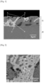
- FIG. 1 shows a backscattered electron image (BSE image) of an example of the coating layer of the coated steel sheet of the present disclosure taken with an SEM at a magnification of 2000x.
- BSE image backscattered electron image
- the coated steel sheet has, for example, a coating layer 1, a steel sheet 2, and an interfacial alloy layer 3 composed of an Al-Fe intermetallic compound between the coating layer 1 and the steel sheet 2.
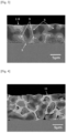
- the structure of the coating layer 1 is mainly constituted with a granular Mg 2 Sn phase-containing structure 4, and a dendritic structure 5. Further, as shown in FIG. 2 , which is an enlarged view of the region A in FIG. 1 , the granular Mg 2 Sn phase-containing structure 4 has a structure in which a granular Mg 2 Sn phase 8 with a crystal grain size of less than 1 ⁇ m is dispersed in a Zn phase 7.
- the dendritic structure 5 corresponds to the gray-colored region as well as the black-colored region surrounded by the former region.
- the difference in color between the two regions is due to the difference in the Al concentrations.
- the dendritic structure 5 with a low Al concentration is the gray-colored region
- the gray-colored dendritic structure 5 with a high Al concentration is the black-colored region.
- the coating layer 1 may occasionally contain a massive MgZn 2 phase 6 (see FIG. 1 and FIG. 2 ), a massive Zn phase 10 (see FIG. 3 ), and a Zn/Al/MgZn 2 ternary eutectic structure 9 (see FIG. 3 ).
- the granular Mg 2 Sn phase-containing structure is constituted with a Zn phase and a granular Mg 2 Sn phase having a crystal grain size of less than 1 ⁇ m dispersed in the Zn phase. That is, in the granular Mg 2 Sn phase-containing structure, the granular Mg 2 Sn phase is contained (that is, included) in the Zn phase.
- the crystal grain size of the granular Mg 2 Sn phase is an equivalent circle diameter.
- the granular Mg 2 Sn phase-containing structure is a structure in which the granular Mg 2 Sn phase with a crystal grain size of less than 1 ⁇ m is dispersed in the Zn phase at a number density of from 1 to 25/ ⁇ m.
- the crystal grain size of the granular Mg 2 Sn phase is less than 1 ⁇ m, the stress to be exerted on the boundary between the granular Mg 2 Sn phase and the Zn phase can be suppressed. For this reason, it is possible to sufficiently maintain the plastic deformability of the granular Mg 2 Sn phase while preventing the granular Mg 2 Sn phase from becoming a starting point of crack generation. Meanwhile, when the crystal grain size of the granular Mg 2 Sn phase exceeds 1 ⁇ m, the stress to be exerted on the boundary between the granular Mg 2 Sn phase and the Zn phase increases and there arises a risk that the granular Mg 2 Sn phase may become a starting point of crack generation, which is not preferable.
- the Mg concentration is from 1 to 10 % by mass
- the Sn concentration is from 1 to 25 % by mass
- the Al concentration is from 1 to 8 % by mass
- the balance consists of Zn, and impurities of less than about 2 % by mass.
- the composition of the entire granular Mg 2 Sn phase-containing structure may also include the above-mentioned optional elements that can be included in the chemical composition of the coating layer.
- a granular phase of an intermetallic compound corresponding to any of the following (1) to (5) is also regarded as the granular Mg 2 Sn phase.
- the granular Mg 2 Sn phase-containing structure includes a Mg 2 Sn phase which is a brittle Mg-containing intermetallic compound as described above, the Mg 2 Sn phase has higher plastic deformability compared to a MgZn 2 phase.
- the Mg 2 Sn phase serves as a supply source of Mg ions in a corrosive environment, and the Mg ions make the corrosion product to an insulating film, so that corrosion under the paint film in a painted state may be suppressed.
- the improving effect of the corrosion resistance after painting and the workability by the granular Mg 2 Sn phase-containing structure increases as the area fraction of the granular Mg 2 Sn phase-containing structure existing in the coating layer becomes higher.
- the lower limit of the area fraction of the granular Mg 2 Sn phase-containing structure is set at 5%. From the viewpoint of reliably improving both the corrosion resistance after painting and the workability, the area fraction of the granular Mg 2 Sn phase-containing structure is preferably 20% or more, and more preferably 30% or more.
- the upper limit of the area fraction of the granular Mg 2 Sn phase-containing structure is set at 65%. From the viewpoint of stable production, the area fraction of the granular Mg 2 Sn phase-containing structure is preferably 60% or less.
- the area fraction of the granular Mg 2 Sn phase-containing structure is from 5 to 65%.
- the area fraction of the granular Mg 2 Sn phase-containing structure is preferably from 20 to 60%, and more preferably from 30 to 60%.
- a dendritic structure is a structure containing a solid solution of Zn and Al.
- a dendritic structure is a structure finely separated to Al phases and Zn phases, and is a structure with the Al concentration of from 15 to 85% and the Zn concentration of from 15 to 85%. Therefore, a dendritic structure is a structure which has fundamentally favorable plastic deformability, and can contribute to improvement of the workability of the coating layer. In addition, it is also a structure contributing to improvement of the seizure resistance.
- the area fraction of the dendritic structure is 35% or more. From the viewpoint of imparting excellent workability to the coating layer, the area fraction of the dendritic structure is preferably 40% or more. Meanwhile, from the viewpoint of production, the upper limit value with respect to the dendritic structure is 95%. From the viewpoint of improving the corrosion resistance after painting and the workability by the granular phase dispersed phase, the dendritic structure occupies preferably 80% or less, more preferably 70% or less.
- the area fraction of the dendritic structure is from 35 to 95%, preferably from 35 or 40 to 80%, and further preferably from 35 or 40 to 70%.
- a massive Zn phase is present in an irregular form in the coating layer, and is a massive Zn phase having an equivalent circle diameter of 2 ⁇ m or more.
- the upper limit of the equivalent circle diameter of the massive Zn phase is not particularly limited, but is, for example, 10 ⁇ m or less.
- the area fraction of the massive Zn phase is from 0 to 20%, preferably from 0 to 10%, and further preferably 0%.
- a massive MgZn 2 phase is present in an irregular form in the coating layer and is a massive Zn phase having an equivalent circle diameter of 1 ⁇ m or more, for instance 2 ⁇ m or more.
- the upper limit of the equivalent circle diameter of a massive MgZn 2 phase is not particularly limited, but is, for example, 10 ⁇ m or less.
- the massive MgZn 2 phase is a brittle phase and tends to become a starting point of cracking at the time of processing. Corrosion may be accelerated in the vicinity of the crack which may cause decrease in corrosion resistance after painting at a processed part. As the area fraction of the massive MgZn 2 phase increases, the corrosion resistance after painting and the workability tend to decrease. Therefore, from the viewpoint of securing corrosion resistance after painting and workability, the area fraction of the massive MgZn 2 phase is 20% or less. From the viewpoint of securing sufficient corrosion resistance after painting and workability, the area fraction of the massive MgZn 2 phase is preferably 5% or less. The area fraction of the massive MgZn 2 phase is most preferably 0% (namely, it is most preferable that a massive MgZn 2 phase is not included).
- the area fraction of the massive MgZn 2 phase is from 0 to 20%, preferably from 0 to 5%, and further preferably 0%.
- the Zn/Al/MgZn 2 ternary eutectic structure is a structure consisting of an Al phase, a Zn phase, and a MgZn phase. Since the size varies depending on the component composition, the shape of each phase is indeterminate. However, since in a eutectic structure, element movement during solidification is suppressed due to transformation at a constant temperature, the respective phases form an intricate pattern, and ordinarily the respective phases finely precipitate (see FIG. 5 ).
- the respective phases are configured such that the Zn phase is large and forms islands, the MgZn phase is second largest and fills the gaps of the Zn phases, and the Al phase is dispersed in a spot pattern among the MgZn 2 phases.
- the constituent phases are not changed by the component composition, the positional relationship depends on the component variation just before solidification and there are a case where the MgZn 2 phase precipitates to form islands, and a case where the Al phase, or the MgZn 2 phase does so.
- the MgZn 2 phase in the ternary eutectic structure which is brittle and susceptible to corrosion, tends to become a starting point of a crack at the time of processing. Corrosion may be accelerated in the vicinity of the crack, which may cause decrease in the corrosion resistance after painting of a processed part. As the area fraction of the Zn/Al/MgZn 2 ternary eutectic structure increases, the corrosion resistance after painting and the workability tend to decrease.
- the area fraction of the Zn/Al/MgZn 2 ternary eutectic structure is 3% or less. From the viewpoint of securing sufficient corrosion resistance after painting and workability, the area fraction of the Zn/Al/MgZn 2 ternary eutectic structure is preferably 0% (namely, it is most preferable that the Zn/Al/MgZn 2 ternary eutectic structure is not included).
- the area fraction of the Zn/Al/MgZn 2 ternary eutectic structure is from 0 to 3%, and preferably 0%.
- the thickness of the coating layer is, for example, about 100 ⁇ m or less. Since the thickness of the entire coating layer depends on the coating conditions, the upper limit and the lower limit of the thickness of the entire coating layer are not particularly restricted. For example, the thickness of the entire coating layer is related to the viscosity and the specific gravity of the coating bath in the conventional hot-dip metal coating method. Further, the coating amount in terms of weight per unit area may be adjusted by the drawing speed of the steel sheet (original sheet for coating) and the intensity of the wiping. Therefore, the lower limit of the thickness of the entire coating layer is, for example, about 2 ⁇ m. Meanwhile, the thickness of the coating layer, which can be produced by a hot-dip metal coating method, is about 95 ⁇ m due to the own weight and uniformity of the coating metal.
- the thickness of the coating layer is preferably from 2 to 95 ⁇ m.
- the coated steel sheet of the present disclosure may further have an interfacial alloy layer composed of an Al-Fe intermetallic compound between the steel sheet and the coating layer.
- an interfacial alloy layer composed of an Al-Fe intermetallic compound of 3 ⁇ m or less is formed between the coating layer and the steel sheet.
- an interfacial alloy layer is not necessarily formed depending on the formation conditions of a coating layer.
- the interfacial alloy layer preferably has a thickness of 100 nm or more in order to ensure the adhesion between the steel substrate (steel sheet) and the coating layer. Meanwhile, since the Al-Fe intermetallic compound composing the interfacial alloy layer is a brittle intermetallic compound, when the thickness of the interfacial alloy layer exceeds 1.5 ⁇ m, the resistance to chipping may be reduced.
- the thickness of the interfacial alloy layer is preferably from 100 nm to 1.5 ⁇ m.
- the interfacial alloy layer Since the interfacial alloy layer is in a solid state in which Si is dissolved, it has a role of suppressing an alloying reaction between the coating layer and the steel substrate.
- the interfacial alloy layer composed of the Al-Fe intermetallic compound is a layer in which the Al 5 Fe phase is the main phase.
- the Al-Fe alloy layer is formed by mutual atomic diffusion of the steel substrate (steel sheet) and the coating bath.
- the interfacial alloy layer may partially contain only a small amount of an AlFe phase, an Al 3 Fe phase, an Al 5 Fe 2 phase, or the like.
- the interfacial alloy layer may also contain various elements such as Zn or Si, which are components of the coating layer.
- various elements such as Zn or Si, which are components of the coating layer.
- Si when Si is incorporated into the interfacial alloy layer, an Al-Fe-Si intermetallic compound is formed in the interfacial alloy layer.
- the interfacial alloy layer may include a pre-coating component (for example, Ni).
- a pre-coating component for example, Ni
- an Al-Fe-Ni intermetallic compound is formed in the interfacial alloy layer.
- the interfacial alloy layer composed of an Al-Fe intermetallic compound means a layer which includes the above-described various modes of alloy layers besides the alloy layer constituted mainly with an Al 5 Fe phase
- the coated steel of the present disclosure is obtained by forming a coating layer on the surface (that is, one side or both sides) of an original sheet for coating by a hot-dip metal coating method.
- a Sendzimir method, a pre-coating method, or the like may be applied.
- Ni may be contained in an "Interfacial alloy layer composed of an Al-Fe intermetallic compound" which may be formed when the coating layer is heated.
- a coating bath is formed by mixing a pure metal or an alloy into the range of the chemical composition of the above-mentioned coating layer, and melting the same in a range of 450 to 650°C as an initial make-up of electrolytic bath.
- an original sheet for coating whose surface is sufficiently reduced is immersed in the coating bath which is kept at a predetermined bath temperature after the initial make-up of electrolytic bath, taken out, and then cooled down thereby completing a coating layer on the surface of the original sheet for coating (steel sheet).
- wiping with a N 2 gas is performed immediately after the original sheet for coating is taken out from the coating bath.
- the cooling rate in the temperature range from immediately after removal of the original sheet for coating from the coating bath (that is, the coating bath temperature) to 320°C is set at 10°C/s or more, and the cooling rate in the temperature range of from 320°C to 280°C is set at 6°C/s or less.
- the backscattered electron image (BSE image) with an SEM of the cross section of the coating layer of the coated steel sheet of the present disclosure shown in FIG. 1 is a backscattered electron image (BSE image) with an SEM of the cross section of the coating layer of the coated steel sheet prepared using the cooling rate of 10°C/s in the temperature range from the temperature of the coating bath to 320°C, and the cooling rate of 6°C/s in the temperature range of from 320°C to 280°C.
- the cooling rate in the temperature range from immediately after removal of the original sheet for coating from the coating bath that is, the coating bath temperature
- the cooling rate in the temperature range of from 320°C to 280°C is 6°C/s or less
- a sufficient amount of the granular Mg 2 Sn phase-containing structure 4 is not necessarily formed.
- the granular Mg 2 Sn phase-containing structure 4 is not formed in the coating layer 1, rather, a Zn/Al/MgZn 2 ternary eutectic structure 9 is formed together with a dendritic structure 5
- the cooling rate is not changed between the temperature range from immediately after removal of the original sheet for coating from the coating bath (that is, the coating bath temperature) to 320°C, and the temperature range of from 320°C to 280°C, a sufficient amount of the granular Mg 2 Sn phase-containing structure 4 is not necessarily formed.
- a granular Mg 2 Sn phase-containing structure 4 is not formed in the coating layer 1. Instead, a structure 11 in which a plate-like Mg 2 Sn phase is mixed in the Zn phase is formed.
- the chemical component of a coating layer is measured by the following method.
- calibration curves for quantitatively analyzing the respective elements are prepared by GDS (radio-frequency glow discharge-optical emission spectroscopy). Thereafter, the chemical components in the depth direction of the coating layer under test are measured.
- an analysis area of 4 mm ⁇ or more is measured at 10 positions or more at a sputtering rate in a range of from 0.04 to 0.1 ⁇ m/sec.
- the average value of the elemental concentration at each place is regarded as the elemental concentration of the chemical composition.
- the area fraction of a structure (provided, a Zn/Al/MgZn 2 ternary eutectic structure is excluded) of the coating layer is measured by the following method.
- a FE-SEM equipped with an EDS energy dispersive X-ray analyzer
- a test piece having a cross section (cross section cut in the thickness direction of the coating layer) of 25 mm in the C direction and 15 mm in the L direction is cut out from the coated steel sheet.
- the obtained test piece is embedded in a resin, and CP (cross session polisher) processing is applied to the cross section of the coating layer to be measured.
- CP cross session polisher
- a backscattered electron image with an SEM and an element mapping image with an EDS of the cross section of the coating layer are created.
- the magnification is 5000x
- the visual field size is 50 ⁇ m long ⁇ 200 ⁇ m wide.
- Each region in a structure is identified based on the backscattered electron image with an SEM and the element mapping image with an EDS.
- a computer image processing is performed such that a range corresponding to the 3 values to be displayed by each structure included in the coating layer exhibits a specific color (for example, only a specific structure is exhibited as a white image, and then the area (number of pixels), etc. of each structure in the visual field is calculated).
- a range corresponding to the 3 values to be displayed by each structure included in the coating layer exhibits a specific color (for example, only a specific structure is exhibited as a white image, and then the area (number of pixels), etc. of each structure in the visual field is calculated).
- the area fraction of each structure of the coating layer is defined as the average value of the area fractions of the structure measured for each of 5 visual fields in an optional cross section (cross section cut in the thickness direction of the coating layer) according to the above-described operation.
- the area fraction of a granular Mg 2 Sn phase-containing structure is the area fraction of a Zn phase, in the region of which presence of the granular Mg 2 Sn phase having a crystal grain size of less than 1 ⁇ m in the number density of from 1 to 25/ ⁇ m 2 is confirmed, provided that the area of the granular Mg 2 Sn phase is also counted.
- the area fraction of a dendritic structure is the area fraction of the region occupied by of a solid solution of Zn and Al (the structure showing the Al concentration of from 15 to 85%, and the Zn concentration of from 15 to 85%).
- the area fraction of a massive MgZn 2 phase is the area fraction of the MgZn 2 phase having an equivalent circle diameter of 1 ⁇ m or more.
- the area fraction of a massive Zn phase is the area fraction of the Zn phase having an equivalent circle diameter of 2 ⁇ m or more.
- the average crystal grain size of a granular Mg 2 Sn phase is measured as follows. AN SEM backscattered electron image of a cross section of the coating layer obtained with respect to the visual field in a size of 10 ⁇ m ⁇ 10 ⁇ m at a magnification of 10000x is visually examined to select granular Mg 2 Sn phases having the top five crystal grain sizes out of granular Mg 2 Sn phases having the crystal grain size of less than 1 ⁇ m recognized in the visual field. This operation is performed for five visual fields, and the arithmetic average of totally 25 crystal grain sizes is regarded as the average crystal grain size of granular Mg 2 Sn phases having the crystal grain size of less than 1 ⁇ m.
- the number density of a granular Mg 2 Sn phase is determined by observing an SEM backscattered electron image of a cross section of the coating layer for the visual field in a size of 12 ⁇ m ⁇ 12 ⁇ m at a magnification of 10000x, counting the number of grain granular Mg 2 Sn phases with a crystal grain size of less than 1 ⁇ m present in an optional granular Mg 2 Sn phase-containing structure in a size of 12 ⁇ m ⁇ 12 ⁇ m, and calculating the number of granular Mg 2 Sn phases per unit area ( ⁇ m 2 ).
- Identification and a measurement of the area fraction of a Zn/Al/MgZn 2 ternary eutectic structure in the coating layer are performed by the following method.
- a structure in an SEM backscattered electron image in which three phases of an Al phase, a Zn phase, and a MgZn 2 phase have formed a eutectic, is identified by the same method as the measurement of the area fraction of each structure in the coating layer.
- a part of the structure is observed by means of a rectangular visual field in a size of 3 ⁇ m ⁇ 4 ⁇ m (diagonal: 5 ⁇ m) at a magnification of 30000x (see FIG. 5 ).
- the structure may be divided into a 1 ⁇ m-square grid-like pattern, and when each phase is included within a single grid in a number of 1 or more respectively, it may be judged as a ternary eutectic structure.
- the above operation is repeated to grasp the outline (region) of the ternary eutectic structure while confirming the continuity of the ternary eutectic structure. Then, the area fraction of the grasped ternary eutectic structure in the coating layer occupied in the SEM backscattered electron image is determined.
- the area fraction of the ternary eutectic structure is defined as the average value of the area fraction of the ternary eutectic structure obtained in at least five visual fields in an optional cross section (cross section cut in the thickness direction of the coating layer) according to the above-described operation.
- the average equivalent circle diameters of a massive MgZn 2 phase and a massive Zn phase are measured by the following method.
- the top five equivalent circular diameters are selected with respect to each identified phase type. Then, this operation is performed for five visual fields, and the arithmetic average of totally 25 equivalent circular diameters is defined as the average equivalent circle diameter of a massive MgZn 2 phase, or a massive Zn phase.
- the thickness of an interfacial alloy layer composed of an Al-Fe intermetallic compound is measured as follows.
- the thickness of the identified interfacial alloy layer is measured at each of optional 5 positions.
- the arithmetic average of the data at 5 positions is defined as the thickness of the interfacial alloy layer.
- a post-treatment applicable to the coated steel sheet of the present disclosure will be described below.
- the chromate treatment there are an electrolytic chromate treatment in which a chromate film is formed by electrolysis, a reaction type chromate treatment in which a film is formed utilizing a reaction with a material, and a surplus treatment solution is washed away, and a coating type chromate treatment in which a treatment solution is coated on an object and then dried without washing with water to form a film. Any of the above may be used.
- electrolytic chromate treatment examples include electrolytic chromate treatments using chromic acid, silica sol, a resin (such as phosphoric acid, acrylic resin, vinyl ester resin, vinyl acetate acrylic emulsion, carboxylated styrene butadiene latex, or diisopropanolamine-modified epoxy resin), and hard silica.
- chromic acid such as phosphoric acid, acrylic resin, vinyl ester resin, vinyl acetate acrylic emulsion, carboxylated styrene butadiene latex, or diisopropanolamine-modified epoxy resin
- a resin such as phosphoric acid, acrylic resin, vinyl ester resin, vinyl acetate acrylic emulsion, carboxylated styrene butadiene latex, or diisopropanolamine-modified epoxy resin
- hard silica such as phosphoric acid, acrylic resin, vinyl ester resin, vinyl acetate acrylic emulsion, carboxylated sty
- Examples of the phosphate treatment include a zinc phosphate treatment, a calcium zinc phosphate treatment, and a manganese phosphate treatment.
- the chromate-free treatment is particularly preferable because it is environmentally-friendly.
- an organic resin a single, or a mixture of two or more organic resins (not modified) may be used, or a single, or a mixture of two or more organic resins to be obtained by modifying at least one other organic resin in the presence of at least one organic resin may be used.
- the organic resin film may contain an optional coloring pigment or rust prevention pigment. It may be also used after it is formed into an aqueous system by dissolving or dispersing it in water.
- the surface of the original sheet for coating was reduced by a N 2 -5% H 2 gas at 800°C in a furnace with an oxygen concentration of 20 ppm or less, cooled with a N 2 gas, and when the temperature of the sheet to be immersed reached the bath temperature +20°C, the sheet was immersed in the coating bath for about 3 sec. After immersion in the coating bath, the sheet was pulled up at a pulling rate of 100 mm/sec. At the time of pulling up, the coating amount was adjusted with an N 2 wiping gas.
- the coating layer was cooled from the temperature of the coating bath to room temperature under the conditions written in Table 1 to produce a coated steel sheet.
- the average equivalent circle diameters of the following structures of the coating layer of the obtained coated steel sheet were measured according to the method described above.
- the average equivalent circle diameter is denoted as "equivalent circle diameter”.
- the thickness of the interfacial alloy layer of the obtained coated steel sheet was measured according to the method described above.
- An SEM backscattered electron image (BSE image) of No. 29 shown in Table 1 was obtained.
- the SEM backscattered electron image (BSE image) of No. 29 shown in Table 1 is shown in FIG. 1 and FIG. 2 .
- the coating layer 1 was mainly constituted with granular Mg 2 Sn phase-containing structures 4 and dendritic structures 5. Then, the average crystal grain size and the number density of the granular Mg 2 Sn phase 8 formed in the granular Mg 2 Sn phase-containing structure 4 shown in FIG. 2 were examined.
- test piece of 30 mm in C direction ⁇ 60 mm in L direction (L) was cut out.
- the test piece was bent by 180° in the C direction (1T bending), and the crest of the worked part of the coating layer was observed with an SEM, and the number of cracks present at the crest (1.6 mm ⁇ 30 mm) was counted.
- test piece in which three test pieces with the same thickness were sandwiched inside, and a test piece in which five test pieces with the same thickness were sandwiched inside were respectively bent in the C direction by 180° (3T bending and 5T bending). Similarly, the numbers of cracks were counted.
- the rating criteria were: in a case where the average number of crack was 0, namely there was no crack, it was rated as "A”; in a case where the average number of cracks was from 1 to 20, it was rated as "B”; in a case where the average number of cracks was from 21 to 100, it was rated as "C”; and in a case where the average number of cracks was 101 or more, it was rated as "D".
- test piece of 50 mm in C direction ⁇ 100 mm in L direction was cut out.
- a Zn phosphoric acid treatment (SD5350 system: Specifications of Nipponpaint Industrial Coatings Co., Ltd.) was applied to the surface of the coating layer of the test piece.
- a 20 ⁇ m-thick paint film was formed on the Zn phosphoric acid-treated surface of the coating layer of the test piece by electropainting (PN110 POWERNIX Gray: Specifications of Nipponpaint Industrial Coatings Co., Ltd.), and baked at a baking temperature of 150°C for 20 min to form an electrodeposited film.
- electropainting PN110 POWERNIX Gray: Specifications of Nipponpaint Industrial Coatings Co., Ltd.
- test piece was subjected to a combined cyclic corrosion test according to JASO (M609-91). And the maximum blistering widths at 8 positions around the cross cuts respectively after execution of 30, 60, 90, and 150 cycles were measured, and the average value was calculated.
- the corrosion resistance after painting was rated by this blistering width.
- the rating criteria were: respectively after execution of 30, 60, 90, and 150 cycles according to JASO (M609-91), in a case where the blistering width from the cross cut was 1 mm or less, it was rated as "A”; in a case where the same was more than 1 mm but not more than 2 mm, it was rated as "B", in a case where the same was more than 2 mm but not more than 4 mm, it was rated as "C”; and in a case where red rust appeared, it was rated as "D".
- a test piece with a coating layer which surface was provided with an electrodeposition coating, was prepared in the same manner as in the evaluation of corrosion resistance after painting. On the electrodeposition coating surface, further intermediate painting, top coat painting, and clear painting were conducted to form the respective paint films, such that the total film thickness became 40 ⁇ m.
- the resistance to chipping was evaluated by this average detachment diameter.
- the smaller average detachment diameter means the better resistance to chipping.
- the rating criteria were: in a case where the average detachment diameter was less than 1.0 mm, it was rated as "A”; in a case where the average detachment diameter was not less than 1.0 mm but less than 1.5 mm, it was rated as "B”; in a case where the average detachment diameter was not less than 1.5 mm but less than 3.0, it was rated as "C”; and in a case where the average detachment diameter was not less than 3.0 mm, it was rated as "D".
- Evaluation of the resistance to seizure of a coating layer was performed as follows.
- Each two test pieces of 80 mm in the C direction and 350 mm in the L direction were cut out from the obtained coated steel sheet.
- a draw-bead working was applied to the two test pieces using jigs that simulate a die and a bead, such that sliding occurred over the length of 150 mm or more between the coating forming layer forming surface of the test piece and the die shoulder as well as the bead portion.
- the radii of curvature of the die shoulder and the bead portion, which were used as jigs in the test were 2 mmR and 5 mmR respectively
- the pushing pressure of the die was 60 kN/m 2
- the drawing rate in the draw-bead working was 2 m/min.
- a lubricating oil (550S, produced by Nihon Parkerizing Co., Ltd.) was applied on to both the surfaces of the test piece at, in total, 10 mg/m 2 .
- each two primary test pieces of 80 mm wide ⁇ 350 mm long were sampled, and a draw-bead working was applied to them using jigs that simulate a die and a bead, such that sliding occurred over the length of 150 mm or more between a surface treated surface of the steel sheet and the die shoulder as well as the bead portion for evaluation of the resistance to seizure.
- the radii of curvature of the die shoulder and the bead portion, which were used as jigs in the test were 2 mmR and 5 mmR respectively
- the pushing pressure of the die was 60 kN/m 2
- the drawing rate in the draw-bead working was 2 m/min.
- a lubricating oil (550S, produced by Nihon Parkerizing Co., Ltd.) was applied on to both the surfaces of the test piece at, in total, 0.5 g/m 2 .
- the rating criteria were: in a case where there was no visually recognizable seizure between the coating layer and the die or bead, it was rated as "A”; in a case where there was visually recognizable mild seizure between the coating layer and the die or bead, it was rated as "B”; and in a case where there was visually recognizable significant seizure between the coating layer and the die or bead, it was rated as "D".
Claims (9)
- Ein beschichtetes Stahlblech, umfassend ein Stahlblech und eine auf zumindest einem Teil einer Oberfläche des Stahlblechs bereitgestellte Überzugsschicht, wobei:die Überzugsschicht eine chemische Zusammensetzung aufweist, die, ausgedrückt als Massen-%:Al: von 15% bis 60%,Mg: von 0,5% bis 8,0%,Sn: von 0,5% bis 20,0%,Si: von 0,05% bis 1,50%,Bi: von 0% bis 5,0%,In: von 0% bis 2,0%,Ca: von 0% bis 3,0%,Y: von 0% bis 0,5%,La: von 0% bis 0,5%,Ce: von 0% bis 0,5%,Cr: von 0% bis 0,25%,Ti: von 0% bis 0,25%,Ni: von 0% bis 0,25%,Co: von 0% bis 0,25%,V: von 0% bis 0,25%,Nb: von 0% bis 0,25%,Cu: von 0% bis 0,25%,Mn: von 0% bis 0,25%,Sr: von 0% bis 0,5%,Sb: von 0% bis 0,5%,Pb: von 0% bis 0,5%,B: von 0% bis 0,5% undeinen Rest bestehend aus Zn und Verunreinigungen umfasst, wobei:die Überzugsschicht eine granuläre Mg2Sn-Phase enthaltende Struktur in einem Flächenanteil von 5 bis 65%, eine Struktur, die eine feste Lösung von Zn und Al enthält, in einem Flächenanteil von 35% bis 95%, eine massive MgZn2-Phase mit einem Äquivalentkreisdurchmesser von 1 µm oder mehr in einem Flächenanteil von 0% bis 20%, eine massive Zn-Phase mit einem Äquivalentkreisdurchmesser von 2 µm oder mehr in einem Flächenanteil von 0% bis 20% und eine ternäre eutektische Zn/Al/MgZn2-Struktur in einem Flächenanteil von 0% bis 3% aufweist; unddie granuläre Mg2Sn-Phase enthaltende Struktur eine Struktur ist, die aus einer Zn-Phase und einer granulären Mg2Sn-Phase mit einer Kristallkorngröße von weniger als 1 µm, dispergiert in der Zn-Phase, besteht.
- Das beschichtete Stahlblech nach Anspruch 1, wobei ein Mg-Gehalt von 0,5% bis 3,0% und ein Sn-Gehalt von 1,0% bis 7,5%, ausgedrückt als Massen-%, beträgt.
- Das beschichtete Stahlblech nach Anspruch 1 oder 2, wobei ein Al-Gehalt von 20% bis 60%, ein Mg-Gehalt von 1,0% bis 2,0%, ein Sn-Gehalt von 1,0% bis 5,0% und ein Si-Gehalt von 0,05% bis 1,0%, ausgedrückt als Massen-%, beträgt.
- Das beschichtete Stahlblech nach einem der Ansprüche 1 bis 3, wobei ein Sn-Gehalt und ein Mg-Gehalt die folgende Formel (1) erfüllen:

- Das beschichtete Stahlblech nach einem der Ansprüche 1 bis 4, wobei der Flächenanteil der granuläre Mg2Sn-Phase enthaltenden Struktur von 20% bis 60% beträgt.
- Das beschichtete Stahlblech nach einem der Ansprüche 1 bis 5, wobei der Flächenanteil der granuläre Mg2Sn-Phase enthaltenden Struktur von 30% bis 60% beträgt.
- Das beschichtete Stahlblech nach einem der Ansprüche 1 bis 6, wobei die Überzugsschicht eine massive MgZn2-Phase mit einem Äquivalentkreisdurchmesser von 1 µm oder mehr in einem Flächenanteil von 0% bis 5% aufweist.
- Das beschichtete Stahlblech nach einem der Ansprüche 1 bis 7, wobei die Überzugsschicht eine massive Zn-Phase mit einem Äquivalentkreisdurchmesser von 2 µm oder mehr in einem Flächenanteil von 0% bis 10% aufweist.
- Das beschichtete Stahlblech nach einem der Ansprüche 1 bis 8, weiter umfassend eine Grenzflächen-Legierungsschicht mit einer Dicke von 100 nm bis 1,5 µm, die aus einer intermetallischen Al-Fe-Verbindung besteht, zwischen dem Stahlblech und der Überzugsschicht.
Applications Claiming Priority (2)
| Application Number | Priority Date | Filing Date | Title |
|---|---|---|---|
| JP2017053150 | 2017-03-17 | ||
| PCT/JP2018/010627 WO2018169084A1 (ja) | 2017-03-17 | 2018-03-16 | めっき鋼板 |
Publications (4)
| Publication Number | Publication Date |
|---|---|
| EP3597786A1 EP3597786A1 (de) | 2020-01-22 |
| EP3597786A4 EP3597786A4 (de) | 2020-08-12 |
| EP3597786C0 EP3597786C0 (de) | 2023-08-09 |
| EP3597786B1 true EP3597786B1 (de) | 2023-08-09 |
Family
ID=63523886
Family Applications (1)
| Application Number | Title | Priority Date | Filing Date |
|---|---|---|---|
| EP18767596.2A Active EP3597786B1 (de) | 2017-03-17 | 2018-03-16 | Beschichtetes stahlblech |
Country Status (15)
| Country | Link |
|---|---|
| US (1) | US11236409B2 (de) |
| EP (1) | EP3597786B1 (de) |
| JP (1) | JP6428975B1 (de) |
| KR (1) | KR102266075B1 (de) |
| CN (1) | CN110431249B (de) |
| AU (1) | AU2018235734B2 (de) |
| BR (1) | BR112019018900A2 (de) |
| ES (1) | ES2958769T3 (de) |
| HU (1) | HUE063660T2 (de) |
| MX (1) | MX2019010927A (de) |
| PH (1) | PH12019502094A1 (de) |
| PL (1) | PL3597786T3 (de) |
| SG (1) | SG11201908424QA (de) |
| TW (1) | TWI666341B (de) |
| WO (1) | WO2018169084A1 (de) |
Families Citing this family (9)
| Publication number | Priority date | Publication date | Assignee | Title |
|---|---|---|---|---|
| KR102354447B1 (ko) * | 2018-09-27 | 2022-03-21 | 주식회사 포스코 | 용접액화취성에 대한 저항성과 도금밀착성이 우수한 고내식 도금강판 |
| KR102613418B1 (ko) * | 2019-06-27 | 2023-12-14 | 닛폰세이테츠 가부시키가이샤 | 도금 강재 |
| BR112022008863A2 (pt) * | 2019-11-14 | 2022-08-23 | Nippon Steel Corp | Material de aço revestido |
| KR102297298B1 (ko) * | 2019-12-06 | 2021-09-03 | 주식회사 포스코 | 굽힘 가공성 및 내식성이 우수한 용융아연도금강판 및 이의 제조방법 |
| JP7406100B2 (ja) | 2020-04-21 | 2023-12-27 | 日本製鉄株式会社 | めっき線及びその製造方法 |
| CN117280070B (zh) * | 2021-09-07 | 2024-04-19 | 日本制铁株式会社 | 热浸镀钢材 |
| CN117545870A (zh) * | 2022-03-31 | 2024-02-09 | 现代制铁株式会社 | 具有优异的加工性和耐腐蚀性的镀层钢材 |
| WO2023238940A1 (ja) * | 2022-06-10 | 2023-12-14 | 日本製鉄株式会社 | Zn-Al-Mg系溶融めっき鋼板 |
| CN115478239A (zh) * | 2022-08-23 | 2022-12-16 | 马鞍山钢铁股份有限公司 | 一种成形性能优良的铝锌镁镀层钢板及其制造方法 |
Family Cites Families (19)
| Publication number | Priority date | Publication date | Assignee | Title |
|---|---|---|---|---|
| JPS467161Y1 (de) | 1968-03-19 | 1971-03-13 | ||
| JPS56152955A (en) * | 1980-04-25 | 1981-11-26 | Nippon Steel Corp | Hot dipping composition for steel sheet coated with zinc alloy by hot dipping |
| DE69730212T2 (de) | 1996-12-13 | 2005-08-18 | Nisshin Steel Co., Ltd. | HEISSTAUCH Zn-Al-Mg BESCHICHTETES STAHLBLECH MIT HERVORRAGENDEN KORROSIONSEIGENSCHAFTEN UND OBERFLÄCHENAUSSEHEN UND VERFAHREN ZUR HERSTELLUNG |
| JP3149129B2 (ja) * | 1997-03-04 | 2001-03-26 | 日新製鋼株式会社 | 耐食性および表面外観の良好な溶融Zn−Al−Mg系めっき鋼板およびその製造法 |
| JP3229292B2 (ja) * | 1999-05-24 | 2001-11-19 | 新日本製鐵株式会社 | 加工部と端面の耐食性に優れためっき鋼板および塗装鋼板 |
| JP3212977B2 (ja) | 1999-08-27 | 2001-09-25 | 新日本製鐵株式会社 | 加工性に優れる溶融めっき鋼材 |
| US6465114B1 (en) | 1999-05-24 | 2002-10-15 | Nippon Steel Corporation | -Zn coated steel material, ZN coated steel sheet and painted steel sheet excellent in corrosion resistance, and method of producing the same |
| JP3567430B2 (ja) | 1999-07-02 | 2004-09-22 | 日新製鋼株式会社 | 耐食性に優れた塗装金属板 |
| JP4136286B2 (ja) * | 1999-08-09 | 2008-08-20 | 新日本製鐵株式会社 | 耐食性に優れたZn−Al−Mg−Si合金めっき鋼材およびその製造方法 |
| JP2001239383A (ja) | 2000-02-25 | 2001-09-04 | Nippon Sharyo Seizo Kaisha Ltd | レーザ切断方法および装置 |
| JP2002180225A (ja) * | 2000-12-13 | 2002-06-26 | Nippon Steel Corp | 耐食性、加工性に優れためっき鋼板 |
| JP2003253416A (ja) | 2002-02-27 | 2003-09-10 | Jfe Steel Kk | 合金化溶融亜鉛めっき鋼板 |
| JP3735360B2 (ja) | 2003-07-01 | 2006-01-18 | 新日本製鐵株式会社 | 外観に優れた溶融Zn−Mg−Al系めっき鋼板の製造方法 |
| JP5895266B2 (ja) | 2013-02-15 | 2016-03-30 | 株式会社川上鉄工所 | 鍛造物の製造方法 |
| JP5994856B2 (ja) | 2013-03-28 | 2016-09-21 | Jfeスチール株式会社 | 溶融Al−Zn系めっき鋼板及びその製造方法 |
| JP6112131B2 (ja) | 2014-04-23 | 2017-04-12 | Jfeスチール株式会社 | 溶融Al−Zn系めっき鋼板及びその製造方法 |
| CN106605007B (zh) * | 2014-09-05 | 2019-03-05 | 新日铁住金株式会社 | 含有准晶体的镀覆钢板以及含有准晶体的镀覆钢板的制造方法 |
| JP6786203B2 (ja) | 2015-09-10 | 2020-11-18 | 五洋建設株式会社 | 潜堤構築材料およびこの材料を用いた潜堤構造 |
| MY193147A (en) * | 2017-01-27 | 2022-09-26 | Nippon Steel Corp | Coated steel product |
-
2018
- 2018-03-16 US US16/493,942 patent/US11236409B2/en active Active
- 2018-03-16 CN CN201880017124.7A patent/CN110431249B/zh active Active
- 2018-03-16 BR BR112019018900A patent/BR112019018900A2/pt not_active IP Right Cessation
- 2018-03-16 KR KR1020197027406A patent/KR102266075B1/ko active IP Right Grant
- 2018-03-16 EP EP18767596.2A patent/EP3597786B1/de active Active
- 2018-03-16 ES ES18767596T patent/ES2958769T3/es active Active
- 2018-03-16 MX MX2019010927A patent/MX2019010927A/es unknown
- 2018-03-16 SG SG11201908424Q patent/SG11201908424QA/en unknown
- 2018-03-16 PL PL18767596.2T patent/PL3597786T3/pl unknown
- 2018-03-16 JP JP2018533719A patent/JP6428975B1/ja active Active
- 2018-03-16 AU AU2018235734A patent/AU2018235734B2/en active Active
- 2018-03-16 WO PCT/JP2018/010627 patent/WO2018169084A1/ja active Application Filing
- 2018-03-16 HU HUE18767596A patent/HUE063660T2/hu unknown
- 2018-03-19 TW TW107109245A patent/TWI666341B/zh active
-
2019
- 2019-09-13 PH PH12019502094A patent/PH12019502094A1/en unknown
Also Published As
| Publication number | Publication date |
|---|---|
| EP3597786C0 (de) | 2023-08-09 |
| CN110431249B (zh) | 2022-03-08 |
| BR112019018900A2 (pt) | 2020-05-19 |
| KR20190120284A (ko) | 2019-10-23 |
| JPWO2018169084A1 (ja) | 2019-03-22 |
| SG11201908424QA (en) | 2019-10-30 |
| WO2018169084A1 (ja) | 2018-09-20 |
| TWI666341B (zh) | 2019-07-21 |
| TW201837207A (zh) | 2018-10-16 |
| EP3597786A1 (de) | 2020-01-22 |
| MX2019010927A (es) | 2019-10-21 |
| AU2018235734B2 (en) | 2020-08-27 |
| KR102266075B1 (ko) | 2021-06-18 |
| AU2018235734A1 (en) | 2019-10-17 |
| US11236409B2 (en) | 2022-02-01 |
| ES2958769T3 (es) | 2024-02-14 |
| PH12019502094A1 (en) | 2020-03-09 |
| US20210079498A1 (en) | 2021-03-18 |
| HUE063660T2 (hu) | 2024-01-28 |
| CN110431249A (zh) | 2019-11-08 |
| JP6428975B1 (ja) | 2018-11-28 |
| PL3597786T3 (pl) | 2023-09-25 |
| EP3597786A4 (de) | 2020-08-12 |
Similar Documents
| Publication | Publication Date | Title |
|---|---|---|
| EP3597787B1 (de) | Beschichtetes stahlblech | |
| EP3597786B1 (de) | Beschichtetes stahlblech | |
| KR102516012B1 (ko) | 도금 강판 | |
| US11371129B2 (en) | Molten Zn-based plated steel sheet having superior corrosion resistance after being coated | |
| EP3266900B1 (de) | Mit geschmolzenem al-zn-mg-si plattiertes stahlblech | |
| KR102384674B1 (ko) | 내식성, 내골링성, 가공성 및 표면 품질이 우수한 도금 강판 및 이의 제조방법 | |
| CN117026132A (zh) | 熔融Al-Zn-Mg-Si-Sr镀覆钢板及其制造方法 | |
| EP4234735A1 (de) | Plattiertes stahlmaterial | |
| EP4060075A1 (de) | Plattiertes stahlmaterial | |
| TWI654338B (zh) | Fused Zn-based plated steel sheet with excellent corrosion resistance after painting |
Legal Events
| Date | Code | Title | Description |
|---|---|---|---|
| STAA | Information on the status of an ep patent application or granted ep patent |
Free format text: STATUS: THE INTERNATIONAL PUBLICATION HAS BEEN MADE |
|
| PUAI | Public reference made under article 153(3) epc to a published international application that has entered the european phase |
Free format text: ORIGINAL CODE: 0009012 |
|
| STAA | Information on the status of an ep patent application or granted ep patent |
Free format text: STATUS: REQUEST FOR EXAMINATION WAS MADE |
|
| 17P | Request for examination filed |
Effective date: 20191017 |
|
| AK | Designated contracting states |
Kind code of ref document: A1 Designated state(s): AL AT BE BG CH CY CZ DE DK EE ES FI FR GB GR HR HU IE IS IT LI LT LU LV MC MK MT NL NO PL PT RO RS SE SI SK SM TR |
|
| AX | Request for extension of the european patent |
Extension state: BA ME |
|
| DAV | Request for validation of the european patent (deleted) | ||
| DAX | Request for extension of the european patent (deleted) | ||
| A4 | Supplementary search report drawn up and despatched |
Effective date: 20200710 |
|
| RIC1 | Information provided on ipc code assigned before grant |
Ipc: C22C 18/04 20060101ALI20200706BHEP Ipc: C23C 2/06 20060101AFI20200706BHEP Ipc: C23C 2/12 20060101ALI20200706BHEP Ipc: C23C 28/02 20060101ALI20200706BHEP Ipc: C22C 21/10 20060101ALI20200706BHEP Ipc: C23C 2/40 20060101ALI20200706BHEP |
|
| STAA | Information on the status of an ep patent application or granted ep patent |
Free format text: STATUS: EXAMINATION IS IN PROGRESS |
|
| 17Q | First examination report despatched |
Effective date: 20220324 |
|
| GRAP | Despatch of communication of intention to grant a patent |
Free format text: ORIGINAL CODE: EPIDOSNIGR1 |
|
| STAA | Information on the status of an ep patent application or granted ep patent |
Free format text: STATUS: GRANT OF PATENT IS INTENDED |
|
| RIC1 | Information provided on ipc code assigned before grant |
Ipc: C23C 28/02 20060101ALI20230131BHEP Ipc: C23C 2/40 20060101ALI20230131BHEP Ipc: C23C 2/12 20060101ALI20230131BHEP Ipc: C23C 2/06 20060101AFI20230131BHEP |
|
| INTG | Intention to grant announced |
Effective date: 20230302 |
|
| GRAS | Grant fee paid |
Free format text: ORIGINAL CODE: EPIDOSNIGR3 |
|
| GRAA | (expected) grant |
Free format text: ORIGINAL CODE: 0009210 |
|
| STAA | Information on the status of an ep patent application or granted ep patent |
Free format text: STATUS: THE PATENT HAS BEEN GRANTED |
|
| AK | Designated contracting states |
Kind code of ref document: B1 Designated state(s): AL AT BE BG CH CY CZ DE DK EE ES FI FR GB GR HR HU IE IS IT LI LT LU LV MC MK MT NL NO PL PT RO RS SE SI SK SM TR |
|
| REG | Reference to a national code |
Ref country code: GB Ref legal event code: FG4D |
|
| REG | Reference to a national code |
Ref country code: CH Ref legal event code: EP |
|
| REG | Reference to a national code |
Ref country code: IE Ref legal event code: FG4D |
|
| REG | Reference to a national code |
Ref country code: DE Ref legal event code: R096 Ref document number: 602018055039 Country of ref document: DE |
|
| U01 | Request for unitary effect filed |
Effective date: 20230822 |
|
| U07 | Unitary effect registered |
Designated state(s): AT BE BG DE DK EE FI FR IT LT LU LV MT NL PT SE SI Effective date: 20230825 |
|
| PG25 | Lapsed in a contracting state [announced via postgrant information from national office to epo] |
Ref country code: GR Free format text: LAPSE BECAUSE OF FAILURE TO SUBMIT A TRANSLATION OF THE DESCRIPTION OR TO PAY THE FEE WITHIN THE PRESCRIBED TIME-LIMIT Effective date: 20231110 |
|
| PG25 | Lapsed in a contracting state [announced via postgrant information from national office to epo] |
Ref country code: IS Free format text: LAPSE BECAUSE OF FAILURE TO SUBMIT A TRANSLATION OF THE DESCRIPTION OR TO PAY THE FEE WITHIN THE PRESCRIBED TIME-LIMIT Effective date: 20231209 |
|
| REG | Reference to a national code |
Ref country code: HU Ref legal event code: AG4A Ref document number: E063660 Country of ref document: HU |
|
| PG25 | Lapsed in a contracting state [announced via postgrant information from national office to epo] |
Ref country code: RS Free format text: LAPSE BECAUSE OF FAILURE TO SUBMIT A TRANSLATION OF THE DESCRIPTION OR TO PAY THE FEE WITHIN THE PRESCRIBED TIME-LIMIT Effective date: 20230809 Ref country code: NO Free format text: LAPSE BECAUSE OF FAILURE TO SUBMIT A TRANSLATION OF THE DESCRIPTION OR TO PAY THE FEE WITHIN THE PRESCRIBED TIME-LIMIT Effective date: 20231109 Ref country code: IS Free format text: LAPSE BECAUSE OF FAILURE TO SUBMIT A TRANSLATION OF THE DESCRIPTION OR TO PAY THE FEE WITHIN THE PRESCRIBED TIME-LIMIT Effective date: 20231209 Ref country code: HR Free format text: LAPSE BECAUSE OF FAILURE TO SUBMIT A TRANSLATION OF THE DESCRIPTION OR TO PAY THE FEE WITHIN THE PRESCRIBED TIME-LIMIT Effective date: 20230809 Ref country code: GR Free format text: LAPSE BECAUSE OF FAILURE TO SUBMIT A TRANSLATION OF THE DESCRIPTION OR TO PAY THE FEE WITHIN THE PRESCRIBED TIME-LIMIT Effective date: 20231110 |
|
| REG | Reference to a national code |
Ref country code: ES Ref legal event code: FG2A Ref document number: 2958769 Country of ref document: ES Kind code of ref document: T3 Effective date: 20240214 |
|
| U20 | Renewal fee paid [unitary effect] |
Year of fee payment: 7 Effective date: 20240207 |