EP3597073B1 - Stoss-resilient gelagerte tisch-vorrichtung - Google Patents
Stoss-resilient gelagerte tisch-vorrichtung Download PDFInfo
- Publication number
- EP3597073B1 EP3597073B1 EP19186293.7A EP19186293A EP3597073B1 EP 3597073 B1 EP3597073 B1 EP 3597073B1 EP 19186293 A EP19186293 A EP 19186293A EP 3597073 B1 EP3597073 B1 EP 3597073B1
- Authority
- EP
- European Patent Office
- Prior art keywords
- damping
- table top
- main side
- side edge
- carrier platform
- Prior art date
- Legal status (The legal status is an assumption and is not a legal conclusion. Google has not performed a legal analysis and makes no representation as to the accuracy of the status listed.)
- Active
Links
Images


Classifications
-
- A—HUMAN NECESSITIES
- A47—FURNITURE; DOMESTIC ARTICLES OR APPLIANCES; COFFEE MILLS; SPICE MILLS; SUCTION CLEANERS IN GENERAL
- A47B—TABLES; DESKS; OFFICE FURNITURE; CABINETS; DRAWERS; GENERAL DETAILS OF FURNITURE
- A47B13/00—Details of tables or desks
- A47B13/003—Connecting table tops to underframes
-
- B—PERFORMING OPERATIONS; TRANSPORTING
- B60—VEHICLES IN GENERAL
- B60N—SEATS SPECIALLY ADAPTED FOR VEHICLES; VEHICLE PASSENGER ACCOMMODATION NOT OTHERWISE PROVIDED FOR
- B60N3/00—Arrangements or adaptations of other passenger fittings, not otherwise provided for
- B60N3/001—Arrangements or adaptations of other passenger fittings, not otherwise provided for of tables or trays
-
- A—HUMAN NECESSITIES
- A47—FURNITURE; DOMESTIC ARTICLES OR APPLIANCES; COFFEE MILLS; SPICE MILLS; SUCTION CLEANERS IN GENERAL
- A47B—TABLES; DESKS; OFFICE FURNITURE; CABINETS; DRAWERS; GENERAL DETAILS OF FURNITURE
- A47B3/00—Folding or stowable tables
- A47B3/12—Stowable tables with detachable top leaves
-
- A—HUMAN NECESSITIES
- A47—FURNITURE; DOMESTIC ARTICLES OR APPLIANCES; COFFEE MILLS; SPICE MILLS; SUCTION CLEANERS IN GENERAL
- A47B—TABLES; DESKS; OFFICE FURNITURE; CABINETS; DRAWERS; GENERAL DETAILS OF FURNITURE
- A47B5/00—Suspended or hinged panels forming a table; Wall tables
-
- B—PERFORMING OPERATIONS; TRANSPORTING
- B61—RAILWAYS
- B61D—BODY DETAILS OR KINDS OF RAILWAY VEHICLES
- B61D37/00—Other furniture or furnishings
-
- F—MECHANICAL ENGINEERING; LIGHTING; HEATING; WEAPONS; BLASTING
- F16—ENGINEERING ELEMENTS AND UNITS; GENERAL MEASURES FOR PRODUCING AND MAINTAINING EFFECTIVE FUNCTIONING OF MACHINES OR INSTALLATIONS; THERMAL INSULATION IN GENERAL
- F16F—SPRINGS; SHOCK-ABSORBERS; MEANS FOR DAMPING VIBRATION
- F16F1/00—Springs
- F16F1/36—Springs made of rubber or other material having high internal friction, e.g. thermoplastic elastomers
-
- F—MECHANICAL ENGINEERING; LIGHTING; HEATING; WEAPONS; BLASTING
- F16—ENGINEERING ELEMENTS AND UNITS; GENERAL MEASURES FOR PRODUCING AND MAINTAINING EFFECTIVE FUNCTIONING OF MACHINES OR INSTALLATIONS; THERMAL INSULATION IN GENERAL
- F16F—SPRINGS; SHOCK-ABSORBERS; MEANS FOR DAMPING VIBRATION
- F16F7/00—Vibration-dampers; Shock-absorbers
- F16F7/12—Vibration-dampers; Shock-absorbers using plastic deformation of members
- F16F7/123—Deformation involving a bending action, e.g. strap moving through multiple rollers, folding of members
-
- F—MECHANICAL ENGINEERING; LIGHTING; HEATING; WEAPONS; BLASTING
- F16—ENGINEERING ELEMENTS AND UNITS; GENERAL MEASURES FOR PRODUCING AND MAINTAINING EFFECTIVE FUNCTIONING OF MACHINES OR INSTALLATIONS; THERMAL INSULATION IN GENERAL
- F16F—SPRINGS; SHOCK-ABSORBERS; MEANS FOR DAMPING VIBRATION
- F16F9/00—Springs, vibration-dampers, shock-absorbers, or similarly-constructed movement-dampers using a fluid or the equivalent as damping medium
- F16F9/02—Springs, vibration-dampers, shock-absorbers, or similarly-constructed movement-dampers using a fluid or the equivalent as damping medium using gas only or vacuum
-
- F—MECHANICAL ENGINEERING; LIGHTING; HEATING; WEAPONS; BLASTING
- F16—ENGINEERING ELEMENTS AND UNITS; GENERAL MEASURES FOR PRODUCING AND MAINTAINING EFFECTIVE FUNCTIONING OF MACHINES OR INSTALLATIONS; THERMAL INSULATION IN GENERAL
- F16F—SPRINGS; SHOCK-ABSORBERS; MEANS FOR DAMPING VIBRATION
- F16F9/00—Springs, vibration-dampers, shock-absorbers, or similarly-constructed movement-dampers using a fluid or the equivalent as damping medium
- F16F9/10—Springs, vibration-dampers, shock-absorbers, or similarly-constructed movement-dampers using a fluid or the equivalent as damping medium using liquid only; using a fluid of which the nature is immaterial
-
- B—PERFORMING OPERATIONS; TRANSPORTING
- B64—AIRCRAFT; AVIATION; COSMONAUTICS
- B64D—EQUIPMENT FOR FITTING IN OR TO AIRCRAFT; FLIGHT SUITS; PARACHUTES; ARRANGEMENT OR MOUNTING OF POWER PLANTS OR PROPULSION TRANSMISSIONS IN AIRCRAFT
- B64D11/00—Passenger or crew accommodation; Flight-deck installations not otherwise provided for
- B64D11/06—Arrangements of seats, or adaptations or details specially adapted for aircraft seats
- B64D11/0638—Arrangements of seats, or adaptations or details specially adapted for aircraft seats with foldable tables, trays or cup holders
-
- F—MECHANICAL ENGINEERING; LIGHTING; HEATING; WEAPONS; BLASTING
- F16—ENGINEERING ELEMENTS AND UNITS; GENERAL MEASURES FOR PRODUCING AND MAINTAINING EFFECTIVE FUNCTIONING OF MACHINES OR INSTALLATIONS; THERMAL INSULATION IN GENERAL
- F16F—SPRINGS; SHOCK-ABSORBERS; MEANS FOR DAMPING VIBRATION
- F16F1/00—Springs
- F16F1/02—Springs made of steel or other material having low internal friction; Wound, torsion, leaf, cup, ring or the like springs, the material of the spring not being relevant
- F16F1/04—Wound springs
-
- F—MECHANICAL ENGINEERING; LIGHTING; HEATING; WEAPONS; BLASTING
- F16—ENGINEERING ELEMENTS AND UNITS; GENERAL MEASURES FOR PRODUCING AND MAINTAINING EFFECTIVE FUNCTIONING OF MACHINES OR INSTALLATIONS; THERMAL INSULATION IN GENERAL
- F16F—SPRINGS; SHOCK-ABSORBERS; MEANS FOR DAMPING VIBRATION
- F16F2224/00—Materials; Material properties
- F16F2224/02—Materials; Material properties solids
-
- F—MECHANICAL ENGINEERING; LIGHTING; HEATING; WEAPONS; BLASTING
- F16—ENGINEERING ELEMENTS AND UNITS; GENERAL MEASURES FOR PRODUCING AND MAINTAINING EFFECTIVE FUNCTIONING OF MACHINES OR INSTALLATIONS; THERMAL INSULATION IN GENERAL
- F16F—SPRINGS; SHOCK-ABSORBERS; MEANS FOR DAMPING VIBRATION
- F16F2224/00—Materials; Material properties
- F16F2224/02—Materials; Material properties solids
- F16F2224/0233—Materials; Material properties solids deforming plastically in operation
Definitions
- the invention relates to a table device with a table top which is coupled to a support strut for the purpose of a holder.
- the support strut can be supported directly on a wall or indirectly on a standing surface.
- Table devices of the type mentioned are used in the prior art as storage devices for objects of the most varied of types.
- the known table devices have the disadvantage that when mounted in a wagon of a train or within a coach, due to a fixed connection to the interior lining of the wagon or coach, they create a bumper edge for sudden acceleration such as in particular a sudden braking process of the vehicle concerned represent a person sitting at this table and ever pose a significant risk of injury to the person concerned after a sudden acceleration that acts as a shock.
- Such a table device is for example from U.S. 5,174,225 A known.
- the object of the invention is therefore to create a table device for mounting inside a movable interior such as a wagon of a train, a ship or a coach, in which there is a risk of injury to a person in the neighborhood in the event of a jerky acceleration, especially in the direction of travel compared to the known table devices is significantly reduced.
- this object is achieved according to the invention in that the table top is attached to a support platform provided with mechanical damping elements and is indirectly connected to the support strut via the mechanical damping elements.
- Preferred embodiments of the invention are the subject matter of the subclaims, the elements of which act in the sense of a further improvement of the approach to the solution of the object on which the invention is based.
- the table top is attached to a support platform provided with mechanical damping elements and is indirectly connected to the support strut via the mechanical damping elements, in the event of a sudden acceleration of one in the vicinity of the Table device located person in relation to the table device a damping of an impact of the person Reached against an edge of the table top in question, whereby a significant reduction in the risk of injury compared to the rigidly suspended table tops of the prior art can be recorded.
- the support strut, the carrier platform and the table top are aligned horizontally.
- the damping elements are oriented horizontally on a carrier platform in order to achieve maximum effectiveness when acceleration is to be expected in the horizontal direction.
- the damping elements are integrated according to the invention within the relevant recesses in a carrier platform.
- the table top of the table device is rectangular and provided with two main side edges aligned parallel to one another and two secondary side edges that are shorter than the main side edges and aligned parallel to one another, the damping elements being aligned at right angles to the main side edges of the table top.
- a shock absorption is provided on a first of the two main side edges and two damping elements are provided for a shock absorption on a second of the two main side edges.
- a first damping element of the two damping elements for damping a shock on the first main side edge is arranged in the area of a first secondary side edge of the table top
- a second damping element of the two damping elements for damping a shock on the first The main side edge is arranged in the area of a second secondary side edge of the table top.
- a first damping element of the two damping elements for damping a shock on the second main side edge is arranged according to the invention in the area of a first secondary side edge of the table top, and a second damping element of the two damping elements for damping a shock on the second
- the main side edge is preferably arranged in the area of a second secondary side edge of the table top.
- a damping element is to be selected depending on the mass of a table top and the hardness of an expected impact of a person against the table top.
- a damping element can be made from an elastic plastic material, the damping element then preferably being designed to be long and narrow and mounted in a form-fitting manner in a long and narrow cavity in the carrier platform.
- a damping element is formed by a plastically compressible damping body which is undulated in a linear direction and which is introduced in a form-fitting manner into a long, narrow cavity in the carrier platform.
- a plastic deformation takes place during an upsetting process of the damping body only from a predetermined, defined strength of an impulse acting on an edge of the table top.
- a damping element can be formed by a spiral spring, a gas spring or a hydraulic spring, which is introduced in a form-fitting manner into a long, narrow cavity in the carrier platform.
- the illustrated table device 100 contains a table top 110 which, for the purpose of attachment to the interior lining of a wagon of a train, is coupled with a support strut 120, the free end of which can be firmly attached to a wall of a wagon.
- the table top 110 is on a with mechanical damping elements 130, 131; 130 ', 131' provided carrier platform 140 is attached and via the mechanical damping elements 130, 131; 130 ', 131' indirectly connected to the support strut 120.
- the support strut 120, the support platform 140 and the table top 110 are aligned horizontally in a conventional manner.
- the damping elements 130, 131; 130 ', 131' are attached to a support platform 140 in a horizontally oriented manner and are integrated into the support platform 140 within a respective recess 132, 133, 132 ', 133'.
- the table top 110 is rectangular and contains two main side edges 111, 112 aligned parallel to one another and two secondary side edges 113, 114 that are shorter than the main side edges 111, 112 and aligned parallel to one another, wherein the damping elements 130, 131; 130 ', 131' are aligned at right angles to the main side edges 111, 112 of the table top 110.
- damping elements 130 ', 131' are provided for damping a shock from a person in the vicinity of the table device 100 on a first of the two main side edges 111, 112 and two damping elements 130, 131 are provided for damping an impact of a person in the vicinity of the table device 100 on a second of the two main side edges 111, 112 is provided.
- a first damping element 130 'of the two damping elements 130', 131 'for damping an impact on the first main side edge 111 is arranged in the area of a first secondary side edge 113 of the table top 110 and a second damping element 131' of the two damping Elements 130 ′, 131 ′ for damping an impact on the first main side edge 111 are arranged in the region of a second secondary side edge 114 of the table top 110.
- a first damping element 130 of the two damping elements 130, 131 for damping an impact on the second main side edge 112 is arranged in the area of a first secondary side edge 113 of the table top 110 and a second damping element 131 of the two damping elements 130, 131 for damping a shock to the second main side edge 112, the table top 110 is arranged in the region of a second secondary side edge 114.
- Each damping element 130, 131; 130 ', 131' is elastic from an undulating in the linear direction compressible damping body formed, the form-fitting in a long and narrow cavity 132, 133; 132 ', 133' of the carrier platform 140 is introduced.
Landscapes
- Engineering & Computer Science (AREA)
- General Engineering & Computer Science (AREA)
- Mechanical Engineering (AREA)
- Transportation (AREA)
- Tables And Desks Characterized By Structural Shape (AREA)
- Vibration Prevention Devices (AREA)
- Passenger Equipment (AREA)
Description
- Die Erfindung betrifft eine Tisch-Vorrichtung mit einer Tischplatte, die zum Zweck einer Halterung mit einer Stützstrebe gekoppelt ist. Die Stützstrebe kann dabei direkt an einer Wand oder indirekt an einer Standoberfläche abgestützt sein.
- Tisch-Vorrichtungen der eingangs genannten Art werden im Stand der Technik als Ablageeinrichtungen für Gegenstände unterschiedlichster Art verwendet. Die bekannten Tisch-Vorrichtungen weisen indes den Nachteil auf, dass sie bei Anbringung in einem Waggon eines Zuges oder innerhalb eines Reisebusses aufgrund einer festen Verbindung mit der Innenauskleidung des Waggons oder Reisebusses bei einer abrupten Beschleunigung wie insbesondere einem plötzlichen Bremsvorgang eines betreffenden Fahrzeuges eine Stoßkante für eine an diesem Tisch sitzende Person darstellen und je nach Heftigkeit einer als Stoß wirkenden ruckartigen Beschleunigung eine u. U. deutliche Verletzungsgefahr für die betreffende Person darstellen. Eine derartige Tisch-Vorrichtung ist beispielsweise aus der
US 5 174 225 A bekannt. - Aufgabe der Erfindung ist es deshalb, eine Tisch-Vorrichtung zur Anbringung im Inneren eines bewegbaren Interieurs wie beispielsweise eines Waggons eines Zuges, eines Schiffes oder eines Reisebusses zu schaffen, bei der eine Verletzungsgefahr einer in der Nachbarschaft befindlichen Person bei einer ruckartigen Beschleunigung insbesondere in Fahrtrichtung gegenüber den bekannten Tisch-Vorrichtungen deutlich gemindert ist.
- Für eine Tisch-Vorrichtung der eingangs genannten Art wird diese Aufgabe erfindungsgemäß dadurch gelöst, dass die Tischplatte an einer mit mechanischen Dämpfungs-Elementen versehenen Trägerplattform befestigt ist und über die mechanischen Dämpfungs-Elemente indirekt mit der Stützstrebe verbunden ist.
- Bevorzugte Ausführungsformen der Erfindung sind Gegenstand der Unteransprüche, deren Elemente im Sinne einer weiteren Verbesserung des Lösungsansatzes der der Erfindung zugrunde gelegten Aufgabe wirken.
- Bei der erfindungsgemäßen Tisch-Vorrichtung wird mit Hilfe der Merkmalskombination, dass die Tischplatte an einer mit mechanischen Dämpfungs-Elementen versehenen Trägerplattform befestigt ist und über die mechanischen Dämpfungs-Elemente indirekt mit der Stützstrebe verbunden ist, im Falle einer plötzlichen Beschleunigung einer in der Nachbarschaft der Tisch-Vorrichtung befindlichen Person in Relation zur Tisch-Vorrichtung eine Dämpfung eines Aufpralls der Person gegen eine Kante der betreffenden Tischplatte erreicht, wodurch eine deutliche Minderung einer Verletzungsgefahr gegenüber den starr suspendierten Tischplatten des Standes der Technik zu verzeichnen ist.
- Erfindungsgemäß ist vorgesehen, dass die Stützstrebe, die Trägerplattform sowie die Tischplatte horizontal ausgerichtet sind.
- Erfindungsgemäß sind die Dämpfungs-Elemente horizontal orientiert an einer Trägerplattform ausgerichtet, um bei einer zu erwartenden Beschleunigung in horizontaler Richtung eine maximale Wirksamkeit zu erbringen.
- Um nicht störend zu wirken und keine Verletzungsgefahr darzustellen und zum Schutz vor ungewollten mechanischen Einwirkungen von außen sind die Dämpfungs-Elemente erfindungsgemäß innerhalb betreffender Aussparungen in eine Trägerplattform integriert.
- Erfindungsgemäß ist die Tischplatte der Tisch-Vorrichtung rechteckförmig ausgebildet und mit zwei zueinander parallel ausgerichteten Hauptseitenkanten und zwei kürzer als die Hauptseitenkanten ausgebildeten, zueinander parallel ausgerichteten Nebenseitenkanten versehen, wobei die Dämpfungs-Elemente rechtwinklig zu den Hauptseitenkanten der Tischplatte ausgerichtet sind.
- Um eine gleichförmige unidirektionale Dämpfung zu bewirken sind dabei erfindungsgemäß jeweils zwei Dämpfungs-Elemente für eine Dämpfung eines Stoßes auf eine erste der beiden Hauptseitenkanten vorgesehen und jeweils zwei Dämpfungs-Elemente für eine Dämpfung eines Stoßes auf eine zweite der beiden Hauptseitenkanten vorgesehen.
- Erfindungsgemäß ist dabei ein erstes Dämpfungs-Element der beiden Dämpfungs-Elemente für eine Dämpfung eines Stoßes auf die erste Hauptseitenkante im Bereich einer ersten Nebenseitenkante der Tischplatte angeordnet, und ein zweites Dämpfungs-Element der beiden Dämpfungs-Elemente für eine Dämpfung eines Stoßes auf die erste Hauptseitenkante ist im Bereich einer zweiten Nebenseitenkante der Tischplatte angeordnet.
- Dementsprechend ist ein erstes Dämpfungs-Element der beiden Dämpfungs-Elemente für eine Dämpfung eines Stoßes auf die zweite Hauptseitenkante erfindungsgemäß im Bereich einer ersten Nebenseitenkante der Tischplatte angeordnet, und ein zweites Dämpfungs-Element der beiden Dämpfungs-Elemente für eine Dämpfung eines Stoßes auf die zweite Hauptseitenkante ist vorzugsweise im Bereich einer zweiten Nebenseitenkante der Tischplatte angeordnet.
- Die Beschaffenheit eines Dämpfungselementes ist je nach Masse einer Tischplatte und der Härte eines zu erwartenden Stoßes einer Person gegen die Tischplatte zu wählen. So kann ein Dämpfungs-Element beispielsweise aus einem elastischen Kunststoffmaterial hergestellt sein, wobei das Dämpfungs-Element dann vorzugsweise langschmal ausgebildet ist und formschlüssig in einer langschmalen Höhlung der Trägerplattform gelagert ist.
- Erfindungsgemäß ist ein Dämpfungs-Element von einem in linearer Richtung onduliert ausgebildeten plastisch stauchbaren Dämpfungskörper gebildet ist, der formschlüssig in eine langschmale Höhlung der Trägerplattform eingebracht ist. Erfindungsgemäß erfolgt dabei eine plastische Verformung bei einem Stauchvorgang des Dämpfungskörpers erst ab einer vorgegeben definierten Stärke eines auf eine Kante der Tischplatte wirkenden Impulses.
- Generell kann ein Dämpfungs-Element von einer Spiralfeder, einer Gasfeder oder einer hydraulischen Feder gebildet sein, die formschlüssig in eine langschmale Höhlung der Trägerplattform eingebracht ist.
- Die erfindungsgemäße Tisch-Vorrichtung wird im Folgenden anhand einer bevorzugten Ausführungsform erläutert, die in den Figuren der Zeichnungen dargestellt sind. Darin zeigen:
- Fig. 1
- eine bevorzugte Ausführungsform der Lagerungselemente einer erfindungsgemäßen TischVorrichtung in einer Explosionsansicht von schräg unten;
- Fig. 2
- in
Fig. 1 dargestellte bevorzugte Ausführungsform der zusammengesetzten Lagerungselemente einer erfindungsgemäßen Tisch-Vorrichtung in einer Ansicht von schräg unten; - Fig. 3
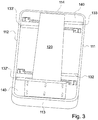
- in
Fig. 1 dargestellte bevorzugte Ausführungsform der zusammengesetzten Lagerungselemente einer erfindungsgemäßen Tisch-Vorrichtung in einer Ansicht von unten. - Die in den
Figuren 1 bis 3 dargestellte erfindungsgemäße Tisch-Vorrichtung 100 enthält eine Tischplatte 110, die zum Zweck einer Befestigung mit der Innenverkleidung eines Waggons eines Zuges mit einer Stützstrebe 120 gekoppelt ist, deren freies Ende an einer Wand eines Waggons fest anbringbar ist. Die Tischplatte 110 ist dabei an einer mit mechanischen Dämpfungs-Elementen 130, 131; 130', 131' versehenen Trägerplattform 140 angebracht und über die mechanischen Dämpfungs-Elemente 130, 131; 130', 131' indirekt mit der Stützstrebe 120 verbunden. Die Stützstrebe 120, die Trägerplattform 140 sowie die Tischplatte 110 sind in herkömmlicher Weise horizontal ausgerichtet. - Die Dämpfungs-Elemente 130, 131; 130', 131' sind horizontal orientiert an einer Trägerplattform 140 angebracht und dabei innerhalb einer jeweiligen Aussparung 132, 133, 132', 133' in die Trägerplattform 140 integriert.
- Die Tischplatte 110 ist rechteckförmig ausgebildet und enthält zwei zueinander parallel ausgerichtete Hauptseitenkanten 111, 112 und zwei kürzer als die Hauptseitenkanten 111, 112 ausgebildete, zueinander parallel ausgerichtete Nebenseitenkanten 113, 114, wobei die Dämpfungs-Elemente 130, 131; 130', 131' rechtwinklig zu den Hauptseitenkanten 111, 112 der Tischplatte 110 ausgerichtet sind.
- Jeweils zwei Dämpfungs-Elemente 130', 131' sind für eine Dämpfung eines Stoßes einer in der Nachbarschaft der Tisch-Vorrichtung 100 befindlichen Person auf eine erste der beiden Hauptseitenkanten 111, 112 vorgesehen und jeweils zwei Dämpfungs-Elemente 130, 131 sind für eine Dämpfung eines Stoßes einer in der Nachbarschaft der Tisch-Vorrichtung 100 befindlichen Person auf eine zweite der beiden Hauptseitenkanten 111, 112 vorgesehen.
- Ein erstes Dämpfungs-Element 130' der beiden Dämpfungs-Elemente 130', 131' für eine Dämpfung eines Stoßes auf die erste Hauptseitenkante 111 ist im Bereich einer ersten Nebenseitenkante 113 der Tischplatte 110 angeordnet und ein zweites Dämpfungs-Element 131' der beiden Dämpfungs-Elemente 130', 131' für eine Dämpfung eines Stoßes auf die erste Hauptseitenkante 111 ist im Bereich einer zweiten Nebenseitenkante 114 der Tischplatte 110 angeordnet.
- Ein erstes Dämpfungs-Element 130 der beiden Dämpfungs-Elemente 130, 131 für eine Dämpfung eines Stoßes auf die zweite Hauptseitenkante 112 ist im Bereich einer ersten Nebenseitenkante 113 der Tischplatte 110 angeordnet und ein zweites Dämpfungs-Element 131 der beiden Dämpfungs-Elemente 130, 131 für eine Dämpfung eines Stoßes auf die zweite Hauptseitenkante 112 ist im Bereich einer zweiten Nebenseitenkante 114 der Tischplatte 110 angeordnet.
- Jedes Dämpfungs-Element 130, 131; 130', 131' ist von einem in linearer Richtung onduliert ausgebildeten elastisch stauchbaren Dämpfungskörper gebildet, der formschlüssig in eine langschmale Höhlung 132, 133; 132', 133' der Trägerplattform 140 eingebracht ist.
- Das oben erläuterte Ausführungsbeispiel der Erfindung dient lediglich dem Zweck eines besseren Verständnisses der durch die Ansprüche vorgegebenen erfindungsgemäßen Lehre, die als solche durch das Ausführungsbeispiel nicht eingeschränkt ist.
- 110
- Tisch-Vorrichtung
- 110
- Tischplatte
- 111, 112
- Hauptseitenkante
- 113, 114
- Nebenseitenkante
- 120
- Stützstrebe
- 130, 131, 130', 131'
- Dämpfungs-Elemente
- 132, 133, 132', 133'
- Aussparungen
- 140
- Trägerplattform
Bezugszeichenliste
Claims (5)
- Tisch-Vorrichtung (100) mit einer Tischplatte (110), die zum Zweck einer Halterung mit einer Stützstrebe (120) gekoppelt ist, wobei die Tischplatte (110) an einer mit mechanischen Dämpfungs-Elementen (130, 131; 130', 131') versehenen Trägerplattform (140) befestigt ist und über die mechanischen Dämpfungs-Elemente (130, 131; 130', 131') indirekt mit der Stützstrebe (120) verbunden ist, die Stützstrebe (120), die Trägerplattform (140) sowie die Tischplatte (110) horizontal ausgerichtet sind und die Dämpfungs-Elemente (130, 131; 130', 131') horizontal orientiert an einer Trägerplattform (140) ausgerichtet sind, wobei die Dämpfungs-Elemente (130, 131; 130', 131') innerhalb betreffender Aussparungen (132, 133; 132', 133') in eine Trägerplattform (140) integriert sind und wobei die Tischplatte (110) rechteckförmig ausgebildet ist und zwei zueinander parallel ausgerichtete Hauptseitenkanten (111, 112) und zwei kürzer als die Hauptseitenkanten (111, 112) ausgebildete, zueinander parallel ausgerichtete Nebenseitenkanten (113, 114) enthält, wobei die Dämpfungs-Elemente (130, 131; 130', 131') rechtwinklig zu den Hauptseitenkanten (111, 112) der Tischplatte (110) ausgerichtet sind, wobei- jeweils zwei Dämpfungs-Elemente (130', 131') für eine Dämpfung eines Stoßes auf eine erste (111) der beiden Hauptseitenkanten (111, 112) vorgesehen sind und jeweils zwei Dämpfungs-Elemente (130, 131) für eine Dämpfung eines Stoßes auf eine zweite (112) der beiden Hauptseitenkanten (111, 112) vorgesehen sind, wobei- ein erstes Dämpfungs-Element (130') der beiden Dämpfungs-Elemente (130', 131') für eine Dämpfung eines Stoßes auf die erste Hauptseitenkante (111) im Bereich einer ersten Nebenseitenkante (113) der Tischplatte (110) angeordnet ist und ein zweites Dämpfungs-Element (131') der beiden Dämpfungs-Elemente (130', 131') für eine Dämpfung eines Stoßes auf die erste Hauptseitenkante (111) im Bereich einer zweiten Nebenseitenkante (114) der Tischplatte (110) angeordnet ist, und- ein erstes Dämpfungs-Element (130) der beiden Dämpfungs-Elemente (130, 131) für eine Dämpfung eines Stoßes auf die zweite Hauptseitenkante (112) im Bereich einer ersten Nebenseitenkante (113) der Tischplatte (110) angeordnet ist und ein zweites Dämpfungs-Element (131) der beiden Dämpfungs-Elemente (130, 131) für eine Dämpfung eines Stoßes auf die zweite Hauptseitenkante (112) im Bereich einer zweiten Nebenseitenkante (114) der Tischplatte (110) angeordnet ist, und wobei- ein Dämpfungs-Element (130, 131; 130', 131') von einem in linearer Richtung onduliert ausgebildeten plastisch stauchbaren Dämpfungskörper gebildet ist, der formschlüssig in eine langschmale Höhlung (132, 133; 132', 133') der Trägerplattform (140) eingebracht ist, wobei- eine plastische Verformung bei einem Stauchvorgang eines Dämpfungskörpers (130, 131; 130', 131') erst ab einer vorgegeben definierten Stärke eines auf eine Kante der Tischplatte (110) wirkenden Impulses erfolgt.
- Tisch-Vorrichtung (100) nach Anspruch 1, dadurch gekennzeichnet, dass ein Dämpfungs-Element (130, 131; 130', 131') aus einem elastischen Kunststoffmaterial hergestellt ist.
- Tisch-Vorrichtung (100) nach einem der vorhergehenden Ansprüche, dadurch gekennzeichnet, dass ein Dämpfungs-Element (130, 131; 130', 131') langschmal ausgebildet ist und formschlüssig in einer langschmalen Höhlung (132, 133; 132', 133') der Trägerplattform (140) gelagert ist.
- Tisch-Vorrichtung (100) nach einem der Ansprüche 1 bis 3, dadurch gekennzeichnet, dass ein Dämpfungs-Element (130, 131; 130', 131') von einer Gasfeder gebildet ist, die formschlüssig in eine langschmale Höhlung (132, 133; 132', 133') der Trägerplattform (140) eingebracht ist.
- Tisch-Vorrichtung (100) nach einem der Ansprüche 1 bis 3, dadurch gekennzeichnet, dass ein Dämpfungs-Element (130, 131; 130', 131') von einer hydraulischen Feder gebildet ist, die formschlüssig in eine langschmale Höhlung (132, 133; 132' 133') der Trägerplattform (140) eingebracht ist.
Applications Claiming Priority (1)
| Application Number | Priority Date | Filing Date | Title |
|---|---|---|---|
| DE102018117399.7A DE102018117399B3 (de) | 2018-07-18 | 2018-07-18 | Stoss-resilient gelagerte tisch-vorrichtung |
Publications (2)
| Publication Number | Publication Date |
|---|---|
| EP3597073A1 EP3597073A1 (de) | 2020-01-22 |
| EP3597073B1 true EP3597073B1 (de) | 2021-09-08 |
Family
ID=68337054
Family Applications (1)
| Application Number | Title | Priority Date | Filing Date |
|---|---|---|---|
| EP19186293.7A Active EP3597073B1 (de) | 2018-07-18 | 2019-07-15 | Stoss-resilient gelagerte tisch-vorrichtung |
Country Status (4)
| Country | Link |
|---|---|
| US (1) | US10829021B2 (de) |
| EP (1) | EP3597073B1 (de) |
| DE (1) | DE102018117399B3 (de) |
| ES (1) | ES2898998T3 (de) |
Families Citing this family (4)
| Publication number | Priority date | Publication date | Assignee | Title |
|---|---|---|---|---|
| IT201800020806A1 (it) * | 2018-12-21 | 2020-06-21 | Ciesse S P A | Tavolo di arredo per un mezzo di trasporto |
| DE102019209658A1 (de) * | 2019-07-02 | 2021-01-07 | Siemens Mobility GmbH | Vorrichtung für ein Schienenfahrzeug und Schienenfahrzeug |
| US11718215B2 (en) * | 2021-10-04 | 2023-08-08 | Airworthy, Inc. | Energy absorbing table for vehicles |
| AT525871B1 (de) * | 2022-07-07 | 2023-09-15 | Seisenbacher Gmbh | Tisch mit beweglichem Führungselement |
Citations (1)
| Publication number | Priority date | Publication date | Assignee | Title |
|---|---|---|---|---|
| EP3081112A1 (de) * | 2015-04-14 | 2016-10-19 | Cerantola S.P.A. | Vorrichtung zum kippen und verriegeln der auflagefläche eines tisches |
Family Cites Families (26)
| Publication number | Priority date | Publication date | Assignee | Title |
|---|---|---|---|---|
| US3985374A (en) * | 1975-07-07 | 1976-10-12 | Tadeusz Powaska | Automobile passenger's individual table |
| US5174225A (en) * | 1990-09-05 | 1992-12-29 | Colby Metal, Inc. | Releasable and tiltable table top |
| US5658050A (en) * | 1996-01-11 | 1997-08-19 | Milsco Manufacturing Company | Vehicle seat with inflatable bladder |
| US6182583B1 (en) * | 1997-09-08 | 2001-02-06 | John E. Larson | Height adjustable pedestal for chairs and tables |
| EP1195307B1 (de) * | 2000-10-06 | 2003-09-10 | Saira Alluminio SpA | Stossdämpfender Tisch, insbesondere für Transportmittel |
| DE102009034511A1 (de) * | 2009-07-23 | 2011-01-27 | Siemens Aktiengesellschaft | Vorrichtung zur Anbindung eines Tisches an die Seitenwand eines Fahrzeuges |
| US20110206894A1 (en) * | 2010-02-24 | 2011-08-25 | Tsai Irwin Y W | Crash Energy Absorbing Furniture Top |
| US8182023B2 (en) * | 2010-03-16 | 2012-05-22 | Sabic Innovative Plastics Ip B.V. | Plastically deformable spring energy management systems and methods for making and using the same |
| US9518629B2 (en) * | 2011-03-14 | 2016-12-13 | Robert Gilkes | Protective device for sports equipment |
| US20130071609A1 (en) * | 2011-09-19 | 2013-03-21 | MitiGator, LLC | Cushioning structure |
| US8985216B2 (en) * | 2012-01-20 | 2015-03-24 | Baker Hughes Incorporated | Hydraulic shock absorber for sliding sleeves |
| US8667910B2 (en) * | 2012-02-24 | 2014-03-11 | Chingdar Enterprise Co., Ltd. | Table furniture assembling structure |
| FR2994410B1 (fr) * | 2012-08-08 | 2015-10-02 | Materiaux Et Tech Composites S M T C Soc D | Table pour l'amenagement d'un vehicule, en particulier de transport en commun |
| DE102013208362A1 (de) * | 2013-05-07 | 2014-11-13 | Siemens Aktiengesellschaft | Fahrgasttisch |
| TWI544144B (zh) * | 2013-11-19 | 2016-08-01 | Nat Inst Chung Shan Science & Technology | Hydraulic energy conversion device |
| DE202014101504U1 (de) * | 2014-03-31 | 2015-07-06 | Grass Gmbh & Co. Kg | Vorrichtung zur Beeinflussung der Bewegung eines Möbelteils und Möbelteil |
| US9295325B2 (en) * | 2014-06-24 | 2016-03-29 | Kustom Seating Unlimited, Inc. | Energy absorbent table |
| WO2016089759A1 (en) * | 2014-12-01 | 2016-06-09 | Zodiac Seats Us Llc | Tray table assembly |
| DE102015105618A1 (de) * | 2015-04-13 | 2016-10-13 | Recaro Aircraft Seating Gmbh & Co. Kg | Flugzeugsitzvorrichtung |
| KR101694017B1 (ko) * | 2015-06-26 | 2017-01-06 | 현대자동차주식회사 | 차량용 접이식 테이블 어셈블리 |
| FR3041310B1 (fr) * | 2015-09-17 | 2018-10-26 | Alstom Transport Technologies | Dispositif de confort, notamment pour vehicule ferroviaire, comprenant une table amovible perfectionnee |
| WO2017175031A1 (en) * | 2016-04-05 | 2017-10-12 | Nasiri Asghar | Passenger compartment for commercial passenger transportation vehicles |
| CN107191536A (zh) * | 2017-06-28 | 2017-09-22 | 杨舜琦 | 一种多用途减震桌板 |
| FR3071210B1 (fr) * | 2017-09-18 | 2019-10-18 | Alstom Transport Technologies | Dispositif de fixation d'un plateau de table |
| TWI651224B (zh) * | 2017-11-21 | 2019-02-21 | 財團法人金屬工業研究發展中心 | 衝擊吸能裝置 |
| US10485332B2 (en) * | 2018-03-21 | 2019-11-26 | Kustom Seating Unlimited, Inc. | Locking mechanism for a table |
-
2018
- 2018-07-18 DE DE102018117399.7A patent/DE102018117399B3/de active Active
-
2019
- 2019-07-15 EP EP19186293.7A patent/EP3597073B1/de active Active
- 2019-07-15 ES ES19186293T patent/ES2898998T3/es active Active
- 2019-07-18 US US16/515,368 patent/US10829021B2/en active Active
Patent Citations (1)
| Publication number | Priority date | Publication date | Assignee | Title |
|---|---|---|---|---|
| EP3081112A1 (de) * | 2015-04-14 | 2016-10-19 | Cerantola S.P.A. | Vorrichtung zum kippen und verriegeln der auflagefläche eines tisches |
Also Published As
| Publication number | Publication date |
|---|---|
| EP3597073A1 (de) | 2020-01-22 |
| US20200023762A1 (en) | 2020-01-23 |
| ES2898998T3 (es) | 2022-03-09 |
| DE102018117399B3 (de) | 2019-11-14 |
| US10829021B2 (en) | 2020-11-10 |
Similar Documents
| Publication | Publication Date | Title |
|---|---|---|
| EP3597073B1 (de) | Stoss-resilient gelagerte tisch-vorrichtung | |
| DE10308371B4 (de) | Sicherheitseinrichtung | |
| DE1780008A1 (de) | Anordnung eines Sitzes in einem Fahrzeug | |
| AT521048B1 (de) | Tisch für ein fahrzeug | |
| DE112007001067T5 (de) | Druck/Druck-Schloss | |
| DE102012106794A1 (de) | STOßFÄNGERTRÄGERVORRICHTUNG FÜR EIN FAHRZEUG | |
| DE10234928B4 (de) | Stoßdämpfer für ein Zweirad | |
| DE202010016444U1 (de) | Vorrichtung zur Befestigung von Tür- oder Klappenscharnieren oder anderen Elementen an den Türen oder Klappen oder an der Karosserie von Kraftfahrzeugen. | |
| DE102017201356A1 (de) | Sitzträger für einen Fahrzeugsitz | |
| DE102014008712A1 (de) | Fahrzeugfrontstruktur | |
| DE102015110436B3 (de) | Kraftfahrzeug | |
| WO2007042106A1 (de) | Fahrzeugsitz mit einer höhen- und/oder neigungsverstellvorrichtung und verriegelungsmitteln | |
| WO2004087474A1 (de) | Vorruchtung zum schutz von personen bei einem frontalaufprall auf ein kraftfahrzeug | |
| DE102013114157B4 (de) | Türverriegelungsvorrichtung für ein Nutzfahrzeug | |
| EP3643565A1 (de) | Vorrichtung, system und verfahren zum sichern einer last in einem fahrzeug | |
| DE69313577T2 (de) | Verbesserung an Türgriffen mit einer plattenförmigen Handhabe | |
| DE102019119932A1 (de) | Unterfahrschutz | |
| EP3741598B1 (de) | Schwenkbare stossstange | |
| DE102014220703B4 (de) | Anordnung im Bereich eines Montageträgers im Vorderwagen eines Kraftfahrzeuges | |
| DE202010014750U1 (de) | Lagerung für Endpunktlager von Federlatten eines Bettlattenrostes | |
| DE102021123611A1 (de) | Kraftfahrzeugschlossgesperre insbesondere Kraftfahrzeugtürschlossgesperre | |
| DE102005016922A1 (de) | Einrichtung zur Abstützung einer Fronthaube an einem Karosserieteil eines Kraftfahrzeuges | |
| DE19817143A1 (de) | Lagerteil für mindestens eine schwenkbare Rückenlehne eines Fahrzeugsitzes | |
| DE202019106114U1 (de) | Türfeststeller für Nutzfahrzeugaufbauten | |
| EP1907262A1 (de) | Fahrzeugaufbau für nutzfahrzeuge |
Legal Events
| Date | Code | Title | Description |
|---|---|---|---|
| PUAI | Public reference made under article 153(3) epc to a published international application that has entered the european phase |
Free format text: ORIGINAL CODE: 0009012 |
|
| STAA | Information on the status of an ep patent application or granted ep patent |
Free format text: STATUS: THE APPLICATION HAS BEEN PUBLISHED |
|
| AK | Designated contracting states |
Kind code of ref document: A1 Designated state(s): AL AT BE BG CH CY CZ DE DK EE ES FI FR GB GR HR HU IE IS IT LI LT LU LV MC MK MT NL NO PL PT RO RS SE SI SK SM TR |
|
| AX | Request for extension of the european patent |
Extension state: BA ME |
|
| STAA | Information on the status of an ep patent application or granted ep patent |
Free format text: STATUS: REQUEST FOR EXAMINATION WAS MADE |
|
| 17P | Request for examination filed |
Effective date: 20200304 |
|
| STAA | Information on the status of an ep patent application or granted ep patent |
Free format text: STATUS: EXAMINATION IS IN PROGRESS |
|
| 17Q | First examination report despatched |
Effective date: 20201201 |
|
| GRAP | Despatch of communication of intention to grant a patent |
Free format text: ORIGINAL CODE: EPIDOSNIGR1 |
|
| STAA | Information on the status of an ep patent application or granted ep patent |
Free format text: STATUS: GRANT OF PATENT IS INTENDED |
|
| INTG | Intention to grant announced |
Effective date: 20210609 |
|
| GRAS | Grant fee paid |
Free format text: ORIGINAL CODE: EPIDOSNIGR3 |
|
| GRAA | (expected) grant |
Free format text: ORIGINAL CODE: 0009210 |
|
| STAA | Information on the status of an ep patent application or granted ep patent |
Free format text: STATUS: THE PATENT HAS BEEN GRANTED |
|
| AK | Designated contracting states |
Kind code of ref document: B1 Designated state(s): AL AT BE BG CH CY CZ DE DK EE ES FI FR GB GR HR HU IE IS IT LI LT LU LV MC MK MT NL NO PL PT RO RS SE SI SK SM TR |
|
| REG | Reference to a national code |
Ref country code: GB Ref legal event code: FG4D Free format text: NOT ENGLISH |
|
| REG | Reference to a national code |
Ref country code: CH Ref legal event code: EP Ref country code: AT Ref legal event code: REF Ref document number: 1427750 Country of ref document: AT Kind code of ref document: T Effective date: 20210915 |
|
| REG | Reference to a national code |
Ref country code: DE Ref legal event code: R096 Ref document number: 502019002239 Country of ref document: DE |
|
| REG | Reference to a national code |
Ref country code: IE Ref legal event code: FG4D Free format text: LANGUAGE OF EP DOCUMENT: GERMAN |
|
| REG | Reference to a national code |
Ref country code: LT Ref legal event code: MG9D |
|
| REG | Reference to a national code |
Ref country code: NL Ref legal event code: MP Effective date: 20210908 |
|
| PG25 | Lapsed in a contracting state [announced via postgrant information from national office to epo] |
Ref country code: RS Free format text: LAPSE BECAUSE OF FAILURE TO SUBMIT A TRANSLATION OF THE DESCRIPTION OR TO PAY THE FEE WITHIN THE PRESCRIBED TIME-LIMIT Effective date: 20210908 Ref country code: SE Free format text: LAPSE BECAUSE OF FAILURE TO SUBMIT A TRANSLATION OF THE DESCRIPTION OR TO PAY THE FEE WITHIN THE PRESCRIBED TIME-LIMIT Effective date: 20210908 Ref country code: FI Free format text: LAPSE BECAUSE OF FAILURE TO SUBMIT A TRANSLATION OF THE DESCRIPTION OR TO PAY THE FEE WITHIN THE PRESCRIBED TIME-LIMIT Effective date: 20210908 Ref country code: NO Free format text: LAPSE BECAUSE OF FAILURE TO SUBMIT A TRANSLATION OF THE DESCRIPTION OR TO PAY THE FEE WITHIN THE PRESCRIBED TIME-LIMIT Effective date: 20211208 Ref country code: HR Free format text: LAPSE BECAUSE OF FAILURE TO SUBMIT A TRANSLATION OF THE DESCRIPTION OR TO PAY THE FEE WITHIN THE PRESCRIBED TIME-LIMIT Effective date: 20210908 Ref country code: BG Free format text: LAPSE BECAUSE OF FAILURE TO SUBMIT A TRANSLATION OF THE DESCRIPTION OR TO PAY THE FEE WITHIN THE PRESCRIBED TIME-LIMIT Effective date: 20211208 Ref country code: LT Free format text: LAPSE BECAUSE OF FAILURE TO SUBMIT A TRANSLATION OF THE DESCRIPTION OR TO PAY THE FEE WITHIN THE PRESCRIBED TIME-LIMIT Effective date: 20210908 |
|
| PG25 | Lapsed in a contracting state [announced via postgrant information from national office to epo] |
Ref country code: LV Free format text: LAPSE BECAUSE OF FAILURE TO SUBMIT A TRANSLATION OF THE DESCRIPTION OR TO PAY THE FEE WITHIN THE PRESCRIBED TIME-LIMIT Effective date: 20210908 Ref country code: GR Free format text: LAPSE BECAUSE OF FAILURE TO SUBMIT A TRANSLATION OF THE DESCRIPTION OR TO PAY THE FEE WITHIN THE PRESCRIBED TIME-LIMIT Effective date: 20211209 |
|
| REG | Reference to a national code |
Ref country code: ES Ref legal event code: FG2A Ref document number: 2898998 Country of ref document: ES Kind code of ref document: T3 Effective date: 20220309 |
|
| PG25 | Lapsed in a contracting state [announced via postgrant information from national office to epo] |
Ref country code: IS Free format text: LAPSE BECAUSE OF FAILURE TO SUBMIT A TRANSLATION OF THE DESCRIPTION OR TO PAY THE FEE WITHIN THE PRESCRIBED TIME-LIMIT Effective date: 20220108 Ref country code: SM Free format text: LAPSE BECAUSE OF FAILURE TO SUBMIT A TRANSLATION OF THE DESCRIPTION OR TO PAY THE FEE WITHIN THE PRESCRIBED TIME-LIMIT Effective date: 20210908 Ref country code: SK Free format text: LAPSE BECAUSE OF FAILURE TO SUBMIT A TRANSLATION OF THE DESCRIPTION OR TO PAY THE FEE WITHIN THE PRESCRIBED TIME-LIMIT Effective date: 20210908 Ref country code: RO Free format text: LAPSE BECAUSE OF FAILURE TO SUBMIT A TRANSLATION OF THE DESCRIPTION OR TO PAY THE FEE WITHIN THE PRESCRIBED TIME-LIMIT Effective date: 20210908 Ref country code: PT Free format text: LAPSE BECAUSE OF FAILURE TO SUBMIT A TRANSLATION OF THE DESCRIPTION OR TO PAY THE FEE WITHIN THE PRESCRIBED TIME-LIMIT Effective date: 20220110 Ref country code: PL Free format text: LAPSE BECAUSE OF FAILURE TO SUBMIT A TRANSLATION OF THE DESCRIPTION OR TO PAY THE FEE WITHIN THE PRESCRIBED TIME-LIMIT Effective date: 20210908 Ref country code: NL Free format text: LAPSE BECAUSE OF FAILURE TO SUBMIT A TRANSLATION OF THE DESCRIPTION OR TO PAY THE FEE WITHIN THE PRESCRIBED TIME-LIMIT Effective date: 20210908 Ref country code: EE Free format text: LAPSE BECAUSE OF FAILURE TO SUBMIT A TRANSLATION OF THE DESCRIPTION OR TO PAY THE FEE WITHIN THE PRESCRIBED TIME-LIMIT Effective date: 20210908 Ref country code: CZ Free format text: LAPSE BECAUSE OF FAILURE TO SUBMIT A TRANSLATION OF THE DESCRIPTION OR TO PAY THE FEE WITHIN THE PRESCRIBED TIME-LIMIT Effective date: 20210908 Ref country code: AL Free format text: LAPSE BECAUSE OF FAILURE TO SUBMIT A TRANSLATION OF THE DESCRIPTION OR TO PAY THE FEE WITHIN THE PRESCRIBED TIME-LIMIT Effective date: 20210908 |
|
| REG | Reference to a national code |
Ref country code: DE Ref legal event code: R097 Ref document number: 502019002239 Country of ref document: DE |
|
| PLBE | No opposition filed within time limit |
Free format text: ORIGINAL CODE: 0009261 |
|
| STAA | Information on the status of an ep patent application or granted ep patent |
Free format text: STATUS: NO OPPOSITION FILED WITHIN TIME LIMIT |
|
| PG25 | Lapsed in a contracting state [announced via postgrant information from national office to epo] |
Ref country code: DK Free format text: LAPSE BECAUSE OF FAILURE TO SUBMIT A TRANSLATION OF THE DESCRIPTION OR TO PAY THE FEE WITHIN THE PRESCRIBED TIME-LIMIT Effective date: 20210908 |
|
| 26N | No opposition filed |
Effective date: 20220609 |
|
| PG25 | Lapsed in a contracting state [announced via postgrant information from national office to epo] |
Ref country code: SI Free format text: LAPSE BECAUSE OF FAILURE TO SUBMIT A TRANSLATION OF THE DESCRIPTION OR TO PAY THE FEE WITHIN THE PRESCRIBED TIME-LIMIT Effective date: 20210908 |
|
| PG25 | Lapsed in a contracting state [announced via postgrant information from national office to epo] |
Ref country code: IT Free format text: LAPSE BECAUSE OF FAILURE TO SUBMIT A TRANSLATION OF THE DESCRIPTION OR TO PAY THE FEE WITHIN THE PRESCRIBED TIME-LIMIT Effective date: 20210908 |
|
| PG25 | Lapsed in a contracting state [announced via postgrant information from national office to epo] |
Ref country code: MC Free format text: LAPSE BECAUSE OF FAILURE TO SUBMIT A TRANSLATION OF THE DESCRIPTION OR TO PAY THE FEE WITHIN THE PRESCRIBED TIME-LIMIT Effective date: 20210908 |
|
| REG | Reference to a national code |
Ref country code: BE Ref legal event code: MM Effective date: 20220731 |
|
| PG25 | Lapsed in a contracting state [announced via postgrant information from national office to epo] |
Ref country code: LU Free format text: LAPSE BECAUSE OF NON-PAYMENT OF DUE FEES Effective date: 20220715 |
|
| PG25 | Lapsed in a contracting state [announced via postgrant information from national office to epo] |
Ref country code: BE Free format text: LAPSE BECAUSE OF NON-PAYMENT OF DUE FEES Effective date: 20220731 |
|
| PG25 | Lapsed in a contracting state [announced via postgrant information from national office to epo] |
Ref country code: IE Free format text: LAPSE BECAUSE OF NON-PAYMENT OF DUE FEES Effective date: 20220715 |
|
| PGFP | Annual fee paid to national office [announced via postgrant information from national office to epo] |
Ref country code: ES Payment date: 20230801 Year of fee payment: 5 Ref country code: CH Payment date: 20230801 Year of fee payment: 5 |
|
| PGFP | Annual fee paid to national office [announced via postgrant information from national office to epo] |
Ref country code: FR Payment date: 20230706 Year of fee payment: 5 |
|
| GBPC | Gb: european patent ceased through non-payment of renewal fee |
Effective date: 20230715 |
|
| PG25 | Lapsed in a contracting state [announced via postgrant information from national office to epo] |
Ref country code: HU Free format text: LAPSE BECAUSE OF FAILURE TO SUBMIT A TRANSLATION OF THE DESCRIPTION OR TO PAY THE FEE WITHIN THE PRESCRIBED TIME-LIMIT; INVALID AB INITIO Effective date: 20190715 |
|
| PG25 | Lapsed in a contracting state [announced via postgrant information from national office to epo] |
Ref country code: MK Free format text: LAPSE BECAUSE OF FAILURE TO SUBMIT A TRANSLATION OF THE DESCRIPTION OR TO PAY THE FEE WITHIN THE PRESCRIBED TIME-LIMIT Effective date: 20210908 Ref country code: CY Free format text: LAPSE BECAUSE OF FAILURE TO SUBMIT A TRANSLATION OF THE DESCRIPTION OR TO PAY THE FEE WITHIN THE PRESCRIBED TIME-LIMIT Effective date: 20210908 Ref country code: GB Free format text: LAPSE BECAUSE OF NON-PAYMENT OF DUE FEES Effective date: 20230715 |
|
| PG25 | Lapsed in a contracting state [announced via postgrant information from national office to epo] |
Ref country code: MT Free format text: LAPSE BECAUSE OF FAILURE TO SUBMIT A TRANSLATION OF THE DESCRIPTION OR TO PAY THE FEE WITHIN THE PRESCRIBED TIME-LIMIT Effective date: 20210908 |
|
| REG | Reference to a national code |
Ref country code: CH Ref legal event code: PL |
|
| PG25 | Lapsed in a contracting state [announced via postgrant information from national office to epo] |
Ref country code: CH Free format text: LAPSE BECAUSE OF NON-PAYMENT OF DUE FEES Effective date: 20240731 |
|
| PG25 | Lapsed in a contracting state [announced via postgrant information from national office to epo] |
Ref country code: FR Free format text: LAPSE BECAUSE OF NON-PAYMENT OF DUE FEES Effective date: 20240731 |
|
| REG | Reference to a national code |
Ref country code: ES Ref legal event code: FD2A Effective date: 20250828 |
|
| REG | Reference to a national code |
Ref country code: AT Ref legal event code: MM01 Ref document number: 1427750 Country of ref document: AT Kind code of ref document: T Effective date: 20240715 |
|
| PG25 | Lapsed in a contracting state [announced via postgrant information from national office to epo] |
Ref country code: ES Free format text: LAPSE BECAUSE OF NON-PAYMENT OF DUE FEES Effective date: 20240716 |
|
| PGFP | Annual fee paid to national office [announced via postgrant information from national office to epo] |
Ref country code: DE Payment date: 20250526 Year of fee payment: 7 |
|
| PG25 | Lapsed in a contracting state [announced via postgrant information from national office to epo] |
Ref country code: AT Free format text: LAPSE BECAUSE OF NON-PAYMENT OF DUE FEES Effective date: 20240715 |
|
| PG25 | Lapsed in a contracting state [announced via postgrant information from national office to epo] |
Ref country code: TR Free format text: LAPSE BECAUSE OF FAILURE TO SUBMIT A TRANSLATION OF THE DESCRIPTION OR TO PAY THE FEE WITHIN THE PRESCRIBED TIME-LIMIT Effective date: 20210908 |
|
| PGFP | Annual fee paid to national office [announced via postgrant information from national office to epo] |
Ref country code: AT Payment date: 20260410 Year of fee payment: 5 |