EP3593045B1 - Brenner mit verbesserter blende - Google Patents
Brenner mit verbesserter blende Download PDFInfo
- Publication number
- EP3593045B1 EP3593045B1 EP18710405.4A EP18710405A EP3593045B1 EP 3593045 B1 EP3593045 B1 EP 3593045B1 EP 18710405 A EP18710405 A EP 18710405A EP 3593045 B1 EP3593045 B1 EP 3593045B1
- Authority
- EP
- European Patent Office
- Prior art keywords
- light
- light opening
- burner
- opening
- air inlet
- Prior art date
- Legal status (The legal status is an assumption and is not a legal conclusion. Google has not performed a legal analysis and makes no representation as to the accuracy of the status listed.)
- Active
Links
Images


Classifications
-
- F—MECHANICAL ENGINEERING; LIGHTING; HEATING; WEAPONS; BLASTING
- F23—COMBUSTION APPARATUS; COMBUSTION PROCESSES
- F23D—BURNERS
- F23D14/00—Burners for combustion of a gas, e.g. of a gas stored under pressure as a liquid
- F23D14/46—Details
- F23D14/72—Safety devices, e.g. operative in case of failure of gas supply
- F23D14/725—Protection against flame failure by using flame detection devices
-
- F—MECHANICAL ENGINEERING; LIGHTING; HEATING; WEAPONS; BLASTING
- F23—COMBUSTION APPARATUS; COMBUSTION PROCESSES
- F23M—CASINGS, LININGS, WALLS OR DOORS SPECIALLY ADAPTED FOR COMBUSTION CHAMBERS, e.g. FIREBRIDGES; DEVICES FOR DEFLECTING AIR, FLAMES OR COMBUSTION PRODUCTS IN COMBUSTION CHAMBERS; SAFETY ARRANGEMENTS SPECIALLY ADAPTED FOR COMBUSTION APPARATUS; DETAILS OF COMBUSTION CHAMBERS, NOT OTHERWISE PROVIDED FOR
- F23M11/00—Safety arrangements
- F23M11/04—Means for supervising combustion, e.g. windows
- F23M11/045—Means for supervising combustion, e.g. windows by observing the flame
-
- F—MECHANICAL ENGINEERING; LIGHTING; HEATING; WEAPONS; BLASTING
- F23—COMBUSTION APPARATUS; COMBUSTION PROCESSES
- F23N—REGULATING OR CONTROLLING COMBUSTION
- F23N5/00—Systems for controlling combustion
- F23N5/02—Systems for controlling combustion using devices responsive to thermal changes or to thermal expansion of a medium
- F23N5/08—Systems for controlling combustion using devices responsive to thermal changes or to thermal expansion of a medium using light-sensitive elements
-
- F—MECHANICAL ENGINEERING; LIGHTING; HEATING; WEAPONS; BLASTING
- F23—COMBUSTION APPARATUS; COMBUSTION PROCESSES
- F23N—REGULATING OR CONTROLLING COMBUSTION
- F23N5/00—Systems for controlling combustion
- F23N5/24—Preventing development of abnormal or undesired conditions, i.e. safety arrangements
- F23N5/242—Preventing development of abnormal or undesired conditions, i.e. safety arrangements using electronic means
-
- F—MECHANICAL ENGINEERING; LIGHTING; HEATING; WEAPONS; BLASTING
- F23—COMBUSTION APPARATUS; COMBUSTION PROCESSES
- F23D—BURNERS
- F23D2209/00—Safety arrangements
-
- F—MECHANICAL ENGINEERING; LIGHTING; HEATING; WEAPONS; BLASTING
- F23—COMBUSTION APPARATUS; COMBUSTION PROCESSES
- F23D—BURNERS
- F23D2900/00—Special features of, or arrangements for burners using fluid fuels or solid fuels suspended in a carrier gas
- F23D2900/00016—Preventing or reducing deposit build-up on burner parts, e.g. from carbon
-
- F—MECHANICAL ENGINEERING; LIGHTING; HEATING; WEAPONS; BLASTING
- F23—COMBUSTION APPARATUS; COMBUSTION PROCESSES
- F23N—REGULATING OR CONTROLLING COMBUSTION
- F23N2229/00—Flame sensors
-
- F—MECHANICAL ENGINEERING; LIGHTING; HEATING; WEAPONS; BLASTING
- F23—COMBUSTION APPARATUS; COMBUSTION PROCESSES
- F23N—REGULATING OR CONTROLLING COMBUSTION
- F23N2231/00—Fail safe
- F23N2231/06—Fail safe for flame failures
-
- F—MECHANICAL ENGINEERING; LIGHTING; HEATING; WEAPONS; BLASTING
- F23—COMBUSTION APPARATUS; COMBUSTION PROCESSES
- F23N—REGULATING OR CONTROLLING COMBUSTION
- F23N2900/00—Special features of, or arrangements for controlling combustion
- F23N2900/05005—Mounting arrangements for sensing, detecting or measuring devices
Definitions
- the present invention relates to a burner, in particular for a vehicle heater, with a screen which separates an inner combustion area from an outer area.
- motor vehicles are often equipped with vehicle heaters, which in particular serve as auxiliary heaters and / or auxiliary heaters.
- vehicle heaters which in particular serve as auxiliary heaters and / or auxiliary heaters.
- Such heating devices are also used in other environments, for example in boats, caravans and other mobile or stationary areas.
- the same fuel is often burned in the vehicle heater that is also used for combustion in the drive engine of the motor vehicle, that is to say in particular diesel fuel or gasoline.
- This fuel stored in the vehicle must be converted into a gaseous state for the purpose of combustion.
- use is made primarily of the principles of atomization and / or evaporation.
- an atomizer nozzle can be provided for this purpose, by means of which the fuel is first converted into droplet form, in order then to pass into the gaseous state due to the thermal energy present in the vehicle heater.
- the oxidizing agent required for combustion is continuously fed to the combustion area in the vehicle heater in the form of a flow of combustion air.
- a device for flame detection is also assigned to the burners of the vehicle heaters. This is a sensor of whatever type that detects the presence of a flame in the burner and forwards a corresponding signal to a control unit of the vehicle heater.
- control and regulation parameters of the vehicle heater are set, for example in the sense of a modification of the burner operation after successful ignition of the burner or in the event of an intentional or unintentional extinction of the flame, in which case the fuel supply is interrupted in particular.
- FIG Figure 13 An example of a nozzle burner known from the prior art is shown in FIG Figure 13 shown in a partially cut-away representation.
- a detail of this nozzle burner represents Figure 14
- the burner 10 ' has an inner combustion region 16' which is delimited by a funnel-shaped wall 58.
- the funnel-shaped wall 58 is shown partially cut open in this illustration. This allows insight into the inner combustion area 16 '.
- a nozzle 60 can be seen to which fuel can be fed.
- the inner combustion area 16 ' is further delimited by a screen 14', which is shown cut off here, the screen 14 'having an essentially circular disk-shaped shape.
- An edge 64 of the funnel-shaped wall 58 rests on the diaphragm 14 ′.
- the inner combustion area 16 ' is largely delimited by the interaction of the funnel-shaped wall 58 and the diaphragm 14'.
- the funnel-shaped wall 58 tapers starting from the diaphragm 14 'and has an opening 66 on its side facing away from the diaphragm 14' to allow the distribution of fuel and combustion air and the formation of a flame in the further combustion chamber.
- Fuel is fed to the nozzle 60 via a line (not shown here) which passes through the diaphragm 14 'from the side of the diaphragm 14' facing away from the nozzle 60.
- the combustion air required for the combustion is supplied to the inner combustion area 16 ′ via openings 68.
- the diaphragm 14 'itself has a light opening 28 ", which has a diameter of 12 mm, for example. This allows light to exit from the inner combustion area 16' into the outer area 18 'of the burner 10'. This light reaches a light-sensitive sensor, for example a photodiode, which is arranged in the outer area 18 'of the burner 10' and which is used for flame detection.
- the light opening 28 ′′ is covered with a mica disk 70 so that no combustion air can pass through the light opening 28 ′′ into the inner combustion area 16 ′.
- Figure 14 allows a view of the screen 14 'from the side of the screen 14' facing away from the nozzle 60 and the funnel-shaped wall 58; the mica washer 70 fastened to the screen 14 'with the rivets 72 can be fully seen here. It completely covers the light opening 28 ′′.
- the nozzle burner 10 'constructed in this way works largely reliably.
- the mica disk 70 prevents the entry of defective air through the large light opening 28 "of the diaphragm 14 'from the outer area 18' into the inner combustion area 16 '.
- a sensor arranged in the outer area 18' can reliably detect the presence of the flame in the inner combustion area 16 '.
- the invention is based on the object of eliminating the disadvantages of the burners known from the prior art.
- a maintenance-free burner is provided which ensures reliable flame detection, excludes the occurrence of defective air which flows into the inner combustion area and at the same time offers large tolerances in its assembly.
- the present invention describes a burner, in particular for a vehicle heater, with a screen that separates an inner combustion area from an outer area separates, wherein a light-sensitive sensor is arranged in the outer area, wherein at least two separate air inlet openings are provided in the screen, wherein one of the at least two air inlet openings is also designed as a light opening, which also allows light to pass through from the inner combustion area the light-sensitive sensor arranged in the outer area, wherein the at least two air inlet openings are shaped so that the same amounts of combustion air flow into the inner combustion area per unit of time, and wherein the aperture is transparent and / or the light opening is one of the not designed as a light opening Air inlet openings has a different shape, so that an illumination area defined by the light opening is larger than a reference illumination area which is defined by one of the at least two air inlet openings that is not designed as a light opening.
- the light opening just like the remaining air inlet openings, serves to supply combustion air into the inner combustion area, the occurrence of incorrect air flows due to leaks in the area of the screen can be reliably prevented.
- the partial mass flow of combustion air supplied per unit of time can be adjusted and evened out or directed through the diaphragm via the pressure loss.
- the diaphragm can also be viewed as a flow straightener.
- the uniform supply is ensured by the formations of the air inlet openings and the light opening, that is to say by their respective edges surrounding the opening areas.
- the at least one air inlet opening and the light opening have the same pressure loss in the sense of a throttling effect for the combustion air flowing through, which can for example be approximately expressed by an identical hydraulic diameter, provided that the respective outer shape of the at least one air inlet opening and the light opening are not too far from one Circle shape deviates. This ensures that the same amounts of combustion air per unit of time flow through the respective openings.
- essentially the same amounts of combustion air or the same amounts of combustion air are regarded as two amounts of combustion air which differ from one another by a maximum of 20 percent, preferably by a maximum of 10 percent, particularly preferably by a maximum of 5 percent. The smaller of the two combustion air quantities can be viewed as defining the 100 percent.
- two amounts of combustion air can be viewed as essentially the same amounts of combustion air or the same amounts of combustion air, which differ from one another by a maximum of 15 percent, preferably by a maximum of 10 percent, particularly preferably by a maximum of 5 percent.
- the greater of the two combustion air quantities can be viewed as defining 100 percent.
- the "deviation" relates to the amount of combustion air through the light opening compared to the respective amount of combustion air through an air inlet opening.
- the pressure drop across the light opening can be determined experimentally, for example, and matched to the pressure drop across the air inlet openings.
- the reliability of the flame detection by the light-sensitive sensor with respect to incorrect positioning of the diaphragm can also be improved that can occur in particular during assembly.
- the screen is transparent, light can also reach the light-sensitive sensor beyond the edge of the light opening from the inner combustion area. If the illumination area defined by the light opening is larger than the reference illumination area which is defined by one of the at least two air inlet openings, the tolerance to incorrect positioning of the diaphragm is also increased.
- the area that lies in the plane of the light-sensitive sensor and is illuminated by a reference opening with the shape of one of the at least two air inlet openings, which is not designed as a light opening, from the inner combustion area can be defined as the reference illumination area when the reference opening is on would be brought to the intended position for the light opening. If the light-sensitive sensor lies within the reference illumination area, reliable flame detection is possible because it is illuminated.
- the illumination area defined by the light opening itself can be determined in the same way as the reference illumination area.
- the illumination surface can be larger than the reference illumination surface due to the different shape of the light opening from the other air inlet openings, or at least have a greater tolerance with respect to misorientations of the diaphragm, in particular rotations. If the diaphragm is transparent, the area to be illuminated is essentially unlimited. A distinction between the light opening and the air inlet opening is purely formal in the case of a transparent panel, due to the unlimited illumination area.
- the “light opening” is arranged so far away from the light-sensitive sensor that it is only reached by light beams from the inner combustion area that have passed through the transparent material of the transparent screen. This case should also be viewed explicitly as the passage of light through the light opening from the inner combustion area to the light sensor arranged in the outer area.
- the light opening and the air inlet openings can, for example, subsequently be punched, cut, milled, drilled, lasered into the cover or introduced into the cover using another manufacturing method known to the person skilled in the art.
- the screen in the case of a transparent screen, it is also possible for the screen to comprise a light opening which, in the absence of an opening through which air can pass, does not simultaneously serve as an air inlet opening.
- the light opening can be defined as the area of the transparent screen through which the light falls through the transparent material of the screen from the inner combustion area onto the light sensor arranged in the outer area.
- the screen has at least one air inlet opening.
- the screen consists of a metallic material or a heat-resistant plastic or a transparent mineral.
- a heat-resistant plastic which is suitable for the present application belongs, for example, to the class of polyethersulfones.
- polyether sulfones can have a high level of transparency paired with rigidity and temperature resistance.
- a suitable transparent mineral can be mica, for example.
- the at least two air inlet openings jointly define a geometric pattern with a multiple axis of rotation with respect to their respective center points in the plane of the diaphragm. This arrangement allows a particularly uniform supply of combustion air to the inner combustion area through the diaphragm.
- the light opening consists of several individual openings that are separate from one another.
- the reference illumination area defined by the light opening in the plane of the light-sensitive sensor can turn out to be particularly large.
- Shapes for possible individual openings or the light opening as a whole are, for example, rosette shapes, star shapes, grid shapes, unstructured shapes, shapes made up of geometric elements such as circles, rectangles and triangles, and modifications of absolutely symmetrical basic shapes. In any case, however, the specified pressure loss at the light opening must always be guaranteed with sufficient stability of the diaphragm.
- the individual openings, which together form the light opening form a grid pattern.
- the provision of a grid pattern represents In the area of the reference illumination surface defined by the light opening, a substantially uniform brightness of the light emerging from the inner area through the light opening is ensured. Irrespective of any incorrect positioning of the diaphragm, this enables uniform signal detection by the light-sensitive sensor, which is advantageous for flame detection.
- the outer edge of the grid pattern can, for example, resemble a segment of a circular ring, so that the screen has a particularly high tolerance to twisting during assembly. Furthermore, the outer edge of the grating pattern can be viewed as the edge of the light opening.
- the grid pattern can be regular, for example.
- the light opening comprises slot-like areas at least in sections.
- the illumination area defined by the light opening can also be enlarged compared to a reference illumination area by providing intermittent slot-like areas.
- intermittently slot-like areas incorrect positioning of the panel, in particular with regard to a rotation of the panel during assembly, can be compensated for particularly easily.
- the screen is at least partially thermally insulated from other components of the burner.
- Thermal insulation of the screen from other components of the burner can reduce the temperature load on the screen, so that more temperature-sensitive materials, which are usually cheaper or easier to process, can be used to manufacture the screen.
- the thermal insulation of the screen can be provided, for example, in the form of seals on the outer edge of the screen with respect to other components of the burner that delimit the inner combustion chamber.
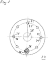
- Figure 1 shows a diaphragm with a first light opening.
- the diaphragm 14 shown is essentially circular.
- a row of air inlet openings 22, 24, 26 with their respective centers 22 ', 24' and 26 ' can be seen.
- further air inlet openings which are not identified in more detail with reference symbols, can be seen.
- In the lower area of the diaphragm 14 there is also an opening specially shaped as a light opening 28 in the diaphragm 14 recognizable.
- the light opening 28 is not closed and also serves for the passage of combustion air through the aperture 14.
- the light opening 28 has a center point 28 '.
- All center points 22 ', 24', 26 ', 28' of the air inlet openings 22, 24, 26 and the further air inlet opening designed as a light opening 28 are arranged concentrically around a center point of the diaphragm 14, which represents a multiple axis of rotation 38.
- the center points of all air inlet openings and the air inlet opening designed as a light opening can be brought into congruence again and again by successive rotations of the diaphragm 14 by 45 ° each, so that in the present case there is an eightfold axis of rotation 38.
- This high symmetry enables combustion air to pass extremely evenly through the aperture 14.
- the in Figure 1 The outer shape of the light opening 28 shown resembles approximately a six-armed 'snowflake'.
- the in Figure 1 The passage area exposed to the light opening 28 shown is dimensioned such that the pressure drop at the light opening 28 corresponds to the respective pressure drop at the individual light openings 22, 24, 26, which are not designed as light openings. In this way, when a burner equipped with the screen 14 is in operation, the same amount of combustion air per unit of time will pass through each of the air inlet openings 22, 24, 26 and the light opening 28 through the screen 14.
- the light opening 28 enlarge the area "illuminated" by the light opening 28, that is to say the illuminated area.
- the light opening 28 including the constrictions contouring the light opening 28 is significantly larger than the other air inlet openings 22, 24, 26, which are not designed as a light opening.
- the light opening 28 resembles a star. Nevertheless, the same amount of combustion air per unit of time passes through the aperture through the light opening 28 as through the other individual air inlet openings.
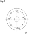
- Figure 2 shows an aperture with a reference aperture.
- a reference opening 40 is shown at the same position of the diaphragm 14.
- the reference opening 40 has the same external shape and the same dimensions as the other air inlet openings 22, 24, 26.
- the reference opening which therefore corresponds to one of the other air inlet openings 22, 24, 26 in terms of its shape, defines a reference illumination area, which is described below in connection with the Figures 10 to 12 will be explained in more detail.
- the light opening 28 can preferably be designed in such a way that its external shape is identical to the outer shapes of the remaining air inlet openings 22, 24, 26. This has the advantage that the panel 14 is particularly easy to manufacture overall. Due to the transparency of the diaphragm 14, the resulting illuminated area is essentially unlimited, regardless of the shape of the light opening 28, since light can pass through the entire diaphragm 14.
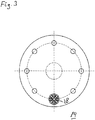
- Figure 3 shows a diaphragm with a second light opening 28.
- the in Figure 3 The light opening 28 shown consists of a plurality of individual openings, each of which is separated from the adjacent openings by thin webs. The multiplicity of individual openings and the thin webs separating these individual openings from one another are together significantly larger than the other air inlet openings that are not designed as light openings 28.
- illustrated light opening 28 is composed as a combination of several geometric shapes. Nevertheless, the same amount of combustion air per unit of time passes through the aperture through the light opening 28 as through the other individual air inlet openings.
- Figure 4 shows a diaphragm with a third light opening.
- light opening 28 just like that in Figure 3 illustrated light opening 28, from a plurality of individual openings separated by thin webs, which in their entirety are reminiscent of the shape of a flower or a rosette made of "pieces of cake".
- the large number of individual openings and the thin webs separating them from one another are together significantly larger in terms of their area than the other air inlet openings, which are not designed as light openings. Nevertheless, the same amount of combustion air per unit of time passes through the aperture through the light opening 28 as through the other individual air inlet openings.
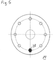
- Figure 5 shows another aperture with a fourth light opening.
- the light opening 28 shown is designed as a regular grid with square grid openings which in their entirety, i.e. the grid openings and the individual webs separating the grid openings, have a significantly larger area than the other air inlet openings that are not designed as light openings 28. Nevertheless, the same amount of combustion air per unit of time passes through the aperture through the light opening 28 as through the other individual air inlet openings.
- Any other geometric basic elements for the grid providing the light opening are also conceivable. This also includes lattices of unstructured shapes that are made up of a multitude of differing polygonal shapes Grid openings and individual webs separating the polygonal grid openings from each other.
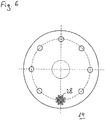
- Figure 6 shows another aperture with a fifth light opening.
- the light opening 28 shown is constructed as a regular arrangement of circular individual openings, each of which is arranged on circular lines around a central opening.
- the individual openings, together with the webs separating the individual openings are significantly larger than the other air inlet openings, which are not designed as light openings. Nevertheless, the same amount of combustion air per unit of time passes through the aperture through the light opening 28 as through the other individual air inlet openings.
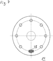
- Figure 7 shows another diaphragm with a sixth light opening.
- the light opening 28 shown comprises a central opening and, separated therefrom by thin webs, a multiplicity of surrounding smaller openings.
- the smaller openings are arranged essentially along a concentric circumferential line on which the center points of the remaining air inlet openings and the light opening 28 itself also lie.
- the outer shape of the large number of individual openings and the thin webs separating them from one another is correspondingly oval. This oval shape makes the in Figure 7
- the light opening 28 shown especially to compensate for a rotation of the diaphragm 14 about the axis of rotation 38
- the light opening 28 shown passes the same amount of combustion air per unit of time through the screen as through the other individual air inlet openings.
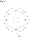
- Figure 8 shows another diaphragm with a seventh light opening.
- the light opening 28 shown consists of a central opening which is laterally framed by crescent moon-like secondary openings. In this way, an oval-like overall shape of the light opening 28, which is subdivided by two webs, is created, which tolerates twisting of the diaphragm particularly well during its assembly Figure 8
- the light opening 28 shown passes the same amount of combustion air per unit of time through the screen as through the other individual air inlet openings.
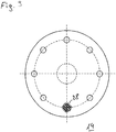
- Figure 9 shows another aperture with an eighth light aperture.
- the light opening shown consists of a large number of narrow slits arranged parallel to one another, each of which is separated from one another by thin webs.
- the orientation of the slots can essentially be chosen freely. Even with the in Figure 9 illustrated light opening 28 the same amount of combustion air per unit of time passes through the screen as through the other individual air inlet openings.
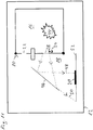
- FIG. 10 shows a vehicle heater with burner in a schematically simplified manner.
- the vehicle heater 12 with the burner 10 can be seen.
- the burner 10 comprises an inner combustion area 16 and an outer area 18, the inner combustion area 16 being separated from the outer area 18 by a screen 14.
- Fuel is fed into the inner combustion region 16 via a fuel feed 42, which can be designed, for example, as an atomizer nozzle with a connected fuel line.
- Combustion air is supplied from the outer area 18 into the inner combustion area 16 through the screen 14, the combustion air flowing through air inlet openings 22 and a light opening 28. In a simplified manner, only one air inlet opening 22 is shown.
- An insulating seal 56 which can in particular be arranged on an edge of the screen 14, can thermally isolate the screen 14 from other components of the burner 10, in particular components that delimit the inner combustion region 16. In addition to the thermal insulation, the insulating seal 56 can also prevent a leak at the edge of the screen, so that no defective air can pass from the outer area 18 into the inner combustion area 16 at the edge of the screen 14.
- a flame 44 is usually present in the inner combustion region 16 during operation of the vehicle heater 12. The flame 44 emits light which exits through the light opening 28 from the inner combustion region 16 into the outer region 18. The outer edge of the light opening 28 delimits the bundle of light rays falling out of the inner combustion region 16, edge rays 48, 50 being indicated.
- a deflection device 46 can also be seen, which can be designed as a reflective surface, for example, and which deflects the beam emerging through the light opening 28 from the inner combustion area 16 in the direction of a light-sensitive sensor 20, which is arranged in a plane 52. As long as the light-sensitive sensor 20 lies in the area between the marginal rays 48, 50, reliable detection of the flame 44 in the inner combustion area 16 by the light-sensitive sensor 20 is guaranteed.
- the position and size of the light opening 28 in the beam path can vary slightly, so that the area illuminated by the light rays that is covered by the edge rays 48 , 50 is limited, may differ in its position from device to device.
- the marginal rays 48, 50 can illuminate an area which is completely next to the light-sensitive area Sensor 20 is located or is only partially illuminated, so that reliable detection of flame 44 is no longer guaranteed.
- the marginal rays 48, 50 define an illumination surface in the plane 52 in which the light-sensitive sensor 20 is arranged, which is indicated below the plane 52 by the double arrow.
- a possible subdivision of the light opening 28 into a multitude of individual openings by thin webs or similar opaque sections is not relevant for the illumination area, since then a multitude of marginal rays produce overlapping individual areas in the plane 52, which together form the illumination area. If the screen 14 itself is transparent, the illuminated surface has practically no edge.
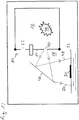
- Figure 11 shows a vehicle heater with burner in a schematically simplified manner with an offset diaphragm.
- the in Figure 11 The vehicle heater 12 shown is the light opening 28 opposite the one in FIG Figure 10
- the situation shown is shifted by an offset 54. Due to the offset 54, the optical conditions change in such a way that the two edge rays 48, 50 in the figure hit the plane 52 offset to the left and the light-sensitive sensor 20 is only partially illuminated.
- the offset 54 of the light opening 28 can arise, for example, as a result of an imprecise assembly of the diaphragm 14, for example due to an installation of the diaphragm 14 that is rotated with respect to a desired position.
- Figure 12 shows a vehicle heater with burner in a schematically simplified manner with reference opening in the panel.
- a reference opening 40 is shown in FIG Figure 12 instead of the one in the Figures 10 and 11 existing light opening 28 in the aperture 14 is provided.
- the reference opening 40 can in particular have the same dimensions as the other air inlet openings 22 in the screen 14.
- the marginal rays 48, 50 given by the reference opening 40 limit the reference illumination area on the plane 52, which is indicated by the smaller double arrow below the plane 52.
- the larger double arrow below corresponds to that in Figure 10 shown double arrow, which belongs to the illumination area which is defined by the light opening 28 which is further opposite the reference opening 40.
Landscapes
- Engineering & Computer Science (AREA)
- Chemical & Material Sciences (AREA)
- Combustion & Propulsion (AREA)
- Mechanical Engineering (AREA)
- General Engineering & Computer Science (AREA)
- Control Of Combustion (AREA)
- Gas Burners (AREA)
- Air-Conditioning For Vehicles (AREA)
Priority Applications (1)
| Application Number | Priority Date | Filing Date | Title |
|---|---|---|---|
| PL18710405T PL3593045T3 (pl) | 2017-03-07 | 2018-03-06 | Palnik z ulepszoną przysłoną |
Applications Claiming Priority (2)
| Application Number | Priority Date | Filing Date | Title |
|---|---|---|---|
| DE102017104769.7A DE102017104769B4 (de) | 2017-03-07 | 2017-03-07 | Brenner mit verbesserter Blende |
| PCT/EP2018/055481 WO2018162486A1 (de) | 2017-03-07 | 2018-03-06 | Brenner mit verbesserter blende |
Publications (2)
| Publication Number | Publication Date |
|---|---|
| EP3593045A1 EP3593045A1 (de) | 2020-01-15 |
| EP3593045B1 true EP3593045B1 (de) | 2021-10-13 |
Family
ID=61622559
Family Applications (1)
| Application Number | Title | Priority Date | Filing Date |
|---|---|---|---|
| EP18710405.4A Active EP3593045B1 (de) | 2017-03-07 | 2018-03-06 | Brenner mit verbesserter blende |
Country Status (7)
| Country | Link |
|---|---|
| US (1) | US11365881B2 (pl) |
| EP (1) | EP3593045B1 (pl) |
| CN (1) | CN110382962B (pl) |
| DE (1) | DE102017104769B4 (pl) |
| PL (1) | PL3593045T3 (pl) |
| RU (1) | RU2721744C1 (pl) |
| WO (1) | WO2018162486A1 (pl) |
Families Citing this family (2)
| Publication number | Priority date | Publication date | Assignee | Title |
|---|---|---|---|---|
| KR20210151149A (ko) * | 2019-04-15 | 2021-12-13 | 온포인트 테크놀로지스, 엘엘씨 | 광학 화염 센서 |
| DE102022134666A1 (de) * | 2022-12-23 | 2024-07-04 | Viessmann Climate Solutions Se | Heizgerät |
Citations (2)
| Publication number | Priority date | Publication date | Assignee | Title |
|---|---|---|---|---|
| JP2009250489A (ja) * | 2008-04-03 | 2009-10-29 | Toshiharu Fukai | バーナーの火炎検知手段 |
| JP2014105906A (ja) * | 2012-11-26 | 2014-06-09 | Miura Co Ltd | 火炎検出装置 |
Family Cites Families (21)
| Publication number | Priority date | Publication date | Assignee | Title |
|---|---|---|---|---|
| GB491714A (en) * | 1937-03-01 | 1938-09-01 | G C Pillinger & Co Ltd | Improvements relating to automatic control systems for heating burners |
| US2304641A (en) * | 1940-05-04 | 1942-12-08 | Brown Instr Co | Control apparatus |
| US3055416A (en) * | 1959-12-29 | 1962-09-25 | Babcock & Wilcox Co | Flame detector arrangements |
| US3185846A (en) * | 1961-05-16 | 1965-05-25 | Bailey Meter Co | Ultra-violet radiation flame monitor |
| DE1221755B (de) * | 1963-12-19 | 1966-07-28 | Appbau Eugen Schrag Kommanditg | Steuer- und Sicherheitsvorrichtung fuer Gas- oder OElfeuerung |
| GB1214521A (en) * | 1968-02-22 | 1970-12-02 | Memco Electronics Ltd | Improvements relating to multi-burner furnaces |
| JPS58190617A (ja) * | 1982-04-28 | 1983-11-07 | Iseki & Co Ltd | 燃焼装置における火炎の検出装置 |
| JPS60501913A (ja) * | 1983-07-25 | 1985-11-07 | クオンタム グル−プ インコ−ポレイテツド | 光電制御装置 |
| DE3501719A1 (de) | 1984-07-28 | 1986-01-30 | Webasto-Werk W. Baier GmbH & Co, 8035 Gauting | Brennstoffbetriebenes heizgeraet |
| US5120975A (en) * | 1990-03-23 | 1992-06-09 | General Electric Company | Gas turbine flame detection system with reflected flame radiation attenuator |
| DE4430196C1 (de) | 1994-08-25 | 1996-01-18 | Eberspaecher J | Fahrzeugheizgerät mit Flammenwächter |
| DE19903767C2 (de) | 1999-01-30 | 2001-05-17 | Webasto Thermosysteme Gmbh | Fahrzeug-Heizgerät mit Gasblasendetektor |
| EP1130318A1 (en) * | 2000-03-03 | 2001-09-05 | IABER S.p.A. | Pasted air box glass |
| DE10110560B4 (de) * | 2001-03-05 | 2009-11-26 | Webasto Ag | Fahrzeug-Heizgerät |
| EP1411573A2 (en) * | 2002-10-16 | 2004-04-21 | Matsushita Electric Industrial Co., Ltd. | Burner, hydrogen generator, and fuel cell power generation system |
| US7775052B2 (en) * | 2004-05-07 | 2010-08-17 | Delavan Inc | Active combustion control system for gas turbine engines |
| AU2008226060B2 (en) * | 2007-03-13 | 2011-04-21 | Thomas Merklein | Method for the camera-assisted detection of the radiation intensity of a gaseous chemical reaction product and uses of said method and corresponding device |
| DE102011077437A1 (de) | 2011-06-10 | 2012-12-13 | Webasto Ag | Fahrzeugheizgerät und Verfahren zum Betreiben eines Fahrzeugheizgerätes |
| JP2015086968A (ja) * | 2013-10-31 | 2015-05-07 | 三菱日立パワーシステムズ株式会社 | 多段減圧装置およびボイラ |
| EP3029647B1 (de) * | 2014-12-04 | 2017-05-31 | Siemens Schweiz AG | Offener Streulichtrauchmelder, insbesondere mit einer Sidelooker-LED |
| CN205079259U (zh) * | 2015-10-22 | 2016-03-09 | 山东多乐采暖设备有限责任公司 | 一种带挡板的观火装置 |
-
2017
- 2017-03-07 DE DE102017104769.7A patent/DE102017104769B4/de not_active Expired - Fee Related
-
2018
- 2018-03-06 CN CN201880016370.0A patent/CN110382962B/zh not_active Expired - Fee Related
- 2018-03-06 RU RU2019127918A patent/RU2721744C1/ru active
- 2018-03-06 EP EP18710405.4A patent/EP3593045B1/de active Active
- 2018-03-06 WO PCT/EP2018/055481 patent/WO2018162486A1/de not_active Ceased
- 2018-03-06 PL PL18710405T patent/PL3593045T3/pl unknown
- 2018-03-06 US US16/489,230 patent/US11365881B2/en active Active
Patent Citations (2)
| Publication number | Priority date | Publication date | Assignee | Title |
|---|---|---|---|---|
| JP2009250489A (ja) * | 2008-04-03 | 2009-10-29 | Toshiharu Fukai | バーナーの火炎検知手段 |
| JP2014105906A (ja) * | 2012-11-26 | 2014-06-09 | Miura Co Ltd | 火炎検出装置 |
Also Published As
| Publication number | Publication date |
|---|---|
| CN110382962A (zh) | 2019-10-25 |
| DE102017104769A1 (de) | 2018-09-13 |
| US11365881B2 (en) | 2022-06-21 |
| DE102017104769B4 (de) | 2019-12-05 |
| PL3593045T3 (pl) | 2022-01-31 |
| EP3593045A1 (de) | 2020-01-15 |
| RU2721744C1 (ru) | 2020-05-21 |
| CN110382962B (zh) | 2021-01-12 |
| WO2018162486A1 (de) | 2018-09-13 |
| US20200011527A1 (en) | 2020-01-09 |
Similar Documents
| Publication | Publication Date | Title |
|---|---|---|
| DE3143394C2 (de) | Wandaufbau für die Brennkammer eines Gasturbinentriebwerks | |
| EP2423599B1 (de) | Verfahren zum Betrieb einer Brenneranordnung sowie Brenneranordnung zur Durchführung des Verfahrens | |
| DE69315233T2 (de) | Gaskochherdbrenner mit drei konzentrischen Flammen | |
| EP2090826B1 (de) | Gasbrennerkopf | |
| WO2015062890A1 (de) | Luftdüse | |
| EP2312953B1 (de) | Backofen mit schwadenapparat | |
| EP1129287B1 (de) | Einspritzdüse für brennkraftmaschinen mit einer ringnut in der düsennadel | |
| DE102017118450A1 (de) | Luftausströmer für ein Fahrzeug | |
| EP3593045B1 (de) | Brenner mit verbesserter blende | |
| DE1529097A1 (de) | Einrichtung zur Regelung bzw. Steuerung der Brennmittelzufuhr fuer Brennersaetze mit Haupt- und Zuendbrenner | |
| EP2618054A2 (de) | Gasbrenner mit wenigstens drei Flammenkreisen | |
| EP3254027B1 (de) | Gasverteilervorrichtung für einen atmosphärischen gasbrenner | |
| DE3012588C2 (de) | Strahlungsbrenner, insbesondere für gasförmigen Brennstoff | |
| DE4301779A1 (de) | Stauscheibe für Öl- und Gasbrenner | |
| DE19538364C5 (de) | Vorrichtung zur Schnellerwärmung von Metall-Preßbolzen | |
| WO2017032424A1 (de) | Kühlluftoptimiertes metallisches hitzeschildelement | |
| DE102013213277A1 (de) | Luftausströmer | |
| DE69708212T2 (de) | Flammenverteilungsvorrichtung für einen Brenner eines Heisswassergerätes | |
| DE60314226T2 (de) | Sprühmusterelement und Kraftstoffeinspritzventil mit demselben | |
| EP3485196B1 (de) | Brenner und fahrzeugheizgerät | |
| DE19713407A1 (de) | Atmosphärischer Gasbrenner | |
| EP1300233A1 (de) | Verfahren und Vorrichtung zum Beheizen eines Plastifizierzylinders | |
| DE69200857T2 (de) | Mischer von Luft und Verbrennungsgas für Gasbrenner von Industrieöfen. | |
| DE3942451C2 (pl) | ||
| DE202017006737U1 (de) | Brenner mit verbesserter Blende |
Legal Events
| Date | Code | Title | Description |
|---|---|---|---|
| STAA | Information on the status of an ep patent application or granted ep patent |
Free format text: STATUS: UNKNOWN |
|
| STAA | Information on the status of an ep patent application or granted ep patent |
Free format text: STATUS: THE INTERNATIONAL PUBLICATION HAS BEEN MADE |
|
| PUAI | Public reference made under article 153(3) epc to a published international application that has entered the european phase |
Free format text: ORIGINAL CODE: 0009012 |
|
| STAA | Information on the status of an ep patent application or granted ep patent |
Free format text: STATUS: REQUEST FOR EXAMINATION WAS MADE |
|
| 17P | Request for examination filed |
Effective date: 20190718 |
|
| AK | Designated contracting states |
Kind code of ref document: A1 Designated state(s): AL AT BE BG CH CY CZ DE DK EE ES FI FR GB GR HR HU IE IS IT LI LT LU LV MC MK MT NL NO PL PT RO RS SE SI SK SM TR |
|
| AX | Request for extension of the european patent |
Extension state: BA ME |
|
| DAV | Request for validation of the european patent (deleted) | ||
| DAX | Request for extension of the european patent (deleted) | ||
| GRAP | Despatch of communication of intention to grant a patent |
Free format text: ORIGINAL CODE: EPIDOSNIGR1 |
|
| STAA | Information on the status of an ep patent application or granted ep patent |
Free format text: STATUS: GRANT OF PATENT IS INTENDED |
|
| INTG | Intention to grant announced |
Effective date: 20210120 |
|
| GRAJ | Information related to disapproval of communication of intention to grant by the applicant or resumption of examination proceedings by the epo deleted |
Free format text: ORIGINAL CODE: EPIDOSDIGR1 |
|
| STAA | Information on the status of an ep patent application or granted ep patent |
Free format text: STATUS: REQUEST FOR EXAMINATION WAS MADE |
|
| INTC | Intention to grant announced (deleted) | ||
| GRAP | Despatch of communication of intention to grant a patent |
Free format text: ORIGINAL CODE: EPIDOSNIGR1 |
|
| STAA | Information on the status of an ep patent application or granted ep patent |
Free format text: STATUS: GRANT OF PATENT IS INTENDED |
|
| INTG | Intention to grant announced |
Effective date: 20210504 |
|
| GRAS | Grant fee paid |
Free format text: ORIGINAL CODE: EPIDOSNIGR3 |
|
| GRAA | (expected) grant |
Free format text: ORIGINAL CODE: 0009210 |
|
| STAA | Information on the status of an ep patent application or granted ep patent |
Free format text: STATUS: THE PATENT HAS BEEN GRANTED |
|
| AK | Designated contracting states |
Kind code of ref document: B1 Designated state(s): AL AT BE BG CH CY CZ DE DK EE ES FI FR GB GR HR HU IE IS IT LI LT LU LV MC MK MT NL NO PL PT RO RS SE SI SK SM TR |
|
| REG | Reference to a national code |
Ref country code: GB Ref legal event code: FG4D Free format text: NOT ENGLISH |
|
| REG | Reference to a national code |
Ref country code: CH Ref legal event code: EP |
|
| REG | Reference to a national code |
Ref country code: DE Ref legal event code: R096 Ref document number: 502018007429 Country of ref document: DE |
|
| REG | Reference to a national code |
Ref country code: IE Ref legal event code: FG4D Free format text: LANGUAGE OF EP DOCUMENT: GERMAN |
|
| REG | Reference to a national code |
Ref country code: AT Ref legal event code: REF Ref document number: 1438447 Country of ref document: AT Kind code of ref document: T Effective date: 20211115 |
|
| REG | Reference to a national code |
Ref country code: LT Ref legal event code: MG9D |
|
| REG | Reference to a national code |
Ref country code: NL Ref legal event code: MP Effective date: 20211013 |
|
| PG25 | Lapsed in a contracting state [announced via postgrant information from national office to epo] |
Ref country code: RS Free format text: LAPSE BECAUSE OF FAILURE TO SUBMIT A TRANSLATION OF THE DESCRIPTION OR TO PAY THE FEE WITHIN THE PRESCRIBED TIME-LIMIT Effective date: 20211013 Ref country code: LT Free format text: LAPSE BECAUSE OF FAILURE TO SUBMIT A TRANSLATION OF THE DESCRIPTION OR TO PAY THE FEE WITHIN THE PRESCRIBED TIME-LIMIT Effective date: 20211013 Ref country code: FI Free format text: LAPSE BECAUSE OF FAILURE TO SUBMIT A TRANSLATION OF THE DESCRIPTION OR TO PAY THE FEE WITHIN THE PRESCRIBED TIME-LIMIT Effective date: 20211013 Ref country code: BG Free format text: LAPSE BECAUSE OF FAILURE TO SUBMIT A TRANSLATION OF THE DESCRIPTION OR TO PAY THE FEE WITHIN THE PRESCRIBED TIME-LIMIT Effective date: 20220113 |
|
| PG25 | Lapsed in a contracting state [announced via postgrant information from national office to epo] |
Ref country code: IS Free format text: LAPSE BECAUSE OF FAILURE TO SUBMIT A TRANSLATION OF THE DESCRIPTION OR TO PAY THE FEE WITHIN THE PRESCRIBED TIME-LIMIT Effective date: 20220213 Ref country code: SE Free format text: LAPSE BECAUSE OF FAILURE TO SUBMIT A TRANSLATION OF THE DESCRIPTION OR TO PAY THE FEE WITHIN THE PRESCRIBED TIME-LIMIT Effective date: 20211013 Ref country code: PT Free format text: LAPSE BECAUSE OF FAILURE TO SUBMIT A TRANSLATION OF THE DESCRIPTION OR TO PAY THE FEE WITHIN THE PRESCRIBED TIME-LIMIT Effective date: 20220214 Ref country code: NO Free format text: LAPSE BECAUSE OF FAILURE TO SUBMIT A TRANSLATION OF THE DESCRIPTION OR TO PAY THE FEE WITHIN THE PRESCRIBED TIME-LIMIT Effective date: 20220113 Ref country code: NL Free format text: LAPSE BECAUSE OF FAILURE TO SUBMIT A TRANSLATION OF THE DESCRIPTION OR TO PAY THE FEE WITHIN THE PRESCRIBED TIME-LIMIT Effective date: 20211013 Ref country code: LV Free format text: LAPSE BECAUSE OF FAILURE TO SUBMIT A TRANSLATION OF THE DESCRIPTION OR TO PAY THE FEE WITHIN THE PRESCRIBED TIME-LIMIT Effective date: 20211013 Ref country code: HR Free format text: LAPSE BECAUSE OF FAILURE TO SUBMIT A TRANSLATION OF THE DESCRIPTION OR TO PAY THE FEE WITHIN THE PRESCRIBED TIME-LIMIT Effective date: 20211013 Ref country code: GR Free format text: LAPSE BECAUSE OF FAILURE TO SUBMIT A TRANSLATION OF THE DESCRIPTION OR TO PAY THE FEE WITHIN THE PRESCRIBED TIME-LIMIT Effective date: 20220114 Ref country code: ES Free format text: LAPSE BECAUSE OF FAILURE TO SUBMIT A TRANSLATION OF THE DESCRIPTION OR TO PAY THE FEE WITHIN THE PRESCRIBED TIME-LIMIT Effective date: 20211013 |
|
| REG | Reference to a national code |
Ref country code: DE Ref legal event code: R097 Ref document number: 502018007429 Country of ref document: DE |
|
| PG25 | Lapsed in a contracting state [announced via postgrant information from national office to epo] |
Ref country code: SM Free format text: LAPSE BECAUSE OF FAILURE TO SUBMIT A TRANSLATION OF THE DESCRIPTION OR TO PAY THE FEE WITHIN THE PRESCRIBED TIME-LIMIT Effective date: 20211013 Ref country code: SK Free format text: LAPSE BECAUSE OF FAILURE TO SUBMIT A TRANSLATION OF THE DESCRIPTION OR TO PAY THE FEE WITHIN THE PRESCRIBED TIME-LIMIT Effective date: 20211013 Ref country code: RO Free format text: LAPSE BECAUSE OF FAILURE TO SUBMIT A TRANSLATION OF THE DESCRIPTION OR TO PAY THE FEE WITHIN THE PRESCRIBED TIME-LIMIT Effective date: 20211013 Ref country code: EE Free format text: LAPSE BECAUSE OF FAILURE TO SUBMIT A TRANSLATION OF THE DESCRIPTION OR TO PAY THE FEE WITHIN THE PRESCRIBED TIME-LIMIT Effective date: 20211013 Ref country code: DK Free format text: LAPSE BECAUSE OF FAILURE TO SUBMIT A TRANSLATION OF THE DESCRIPTION OR TO PAY THE FEE WITHIN THE PRESCRIBED TIME-LIMIT Effective date: 20211013 Ref country code: CZ Free format text: LAPSE BECAUSE OF FAILURE TO SUBMIT A TRANSLATION OF THE DESCRIPTION OR TO PAY THE FEE WITHIN THE PRESCRIBED TIME-LIMIT Effective date: 20211013 |
|
| PLBE | No opposition filed within time limit |
Free format text: ORIGINAL CODE: 0009261 |
|
| STAA | Information on the status of an ep patent application or granted ep patent |
Free format text: STATUS: NO OPPOSITION FILED WITHIN TIME LIMIT |
|
| 26N | No opposition filed |
Effective date: 20220714 |
|
| PG25 | Lapsed in a contracting state [announced via postgrant information from national office to epo] |
Ref country code: MC Free format text: LAPSE BECAUSE OF FAILURE TO SUBMIT A TRANSLATION OF THE DESCRIPTION OR TO PAY THE FEE WITHIN THE PRESCRIBED TIME-LIMIT Effective date: 20211013 Ref country code: AL Free format text: LAPSE BECAUSE OF FAILURE TO SUBMIT A TRANSLATION OF THE DESCRIPTION OR TO PAY THE FEE WITHIN THE PRESCRIBED TIME-LIMIT Effective date: 20211013 |
|
| REG | Reference to a national code |
Ref country code: CH Ref legal event code: PL |
|
| GBPC | Gb: european patent ceased through non-payment of renewal fee |
Effective date: 20220306 |
|
| PG25 | Lapsed in a contracting state [announced via postgrant information from national office to epo] |
Ref country code: SI Free format text: LAPSE BECAUSE OF FAILURE TO SUBMIT A TRANSLATION OF THE DESCRIPTION OR TO PAY THE FEE WITHIN THE PRESCRIBED TIME-LIMIT Effective date: 20211013 |
|
| REG | Reference to a national code |
Ref country code: BE Ref legal event code: MM Effective date: 20220331 |
|
| PG25 | Lapsed in a contracting state [announced via postgrant information from national office to epo] |
Ref country code: LU Free format text: LAPSE BECAUSE OF NON-PAYMENT OF DUE FEES Effective date: 20220306 Ref country code: LI Free format text: LAPSE BECAUSE OF NON-PAYMENT OF DUE FEES Effective date: 20220331 Ref country code: IE Free format text: LAPSE BECAUSE OF NON-PAYMENT OF DUE FEES Effective date: 20220306 Ref country code: GB Free format text: LAPSE BECAUSE OF NON-PAYMENT OF DUE FEES Effective date: 20220306 Ref country code: FR Free format text: LAPSE BECAUSE OF NON-PAYMENT OF DUE FEES Effective date: 20220331 Ref country code: CH Free format text: LAPSE BECAUSE OF NON-PAYMENT OF DUE FEES Effective date: 20220331 |
|
| PG25 | Lapsed in a contracting state [announced via postgrant information from national office to epo] |
Ref country code: BE Free format text: LAPSE BECAUSE OF NON-PAYMENT OF DUE FEES Effective date: 20220331 |
|
| PG25 | Lapsed in a contracting state [announced via postgrant information from national office to epo] |
Ref country code: IT Free format text: LAPSE BECAUSE OF FAILURE TO SUBMIT A TRANSLATION OF THE DESCRIPTION OR TO PAY THE FEE WITHIN THE PRESCRIBED TIME-LIMIT Effective date: 20211013 |
|
| PG25 | Lapsed in a contracting state [announced via postgrant information from national office to epo] |
Ref country code: MK Free format text: LAPSE BECAUSE OF FAILURE TO SUBMIT A TRANSLATION OF THE DESCRIPTION OR TO PAY THE FEE WITHIN THE PRESCRIBED TIME-LIMIT Effective date: 20211013 Ref country code: CY Free format text: LAPSE BECAUSE OF FAILURE TO SUBMIT A TRANSLATION OF THE DESCRIPTION OR TO PAY THE FEE WITHIN THE PRESCRIBED TIME-LIMIT Effective date: 20211013 |
|
| PGFP | Annual fee paid to national office [announced via postgrant information from national office to epo] |
Ref country code: DE Payment date: 20240321 Year of fee payment: 7 |
|
| REG | Reference to a national code |
Ref country code: AT Ref legal event code: MM01 Ref document number: 1438447 Country of ref document: AT Kind code of ref document: T Effective date: 20230306 |
|
| PG25 | Lapsed in a contracting state [announced via postgrant information from national office to epo] |
Ref country code: HU Free format text: LAPSE BECAUSE OF FAILURE TO SUBMIT A TRANSLATION OF THE DESCRIPTION OR TO PAY THE FEE WITHIN THE PRESCRIBED TIME-LIMIT; INVALID AB INITIO Effective date: 20180306 |
|
| PGFP | Annual fee paid to national office [announced via postgrant information from national office to epo] |
Ref country code: PL Payment date: 20240222 Year of fee payment: 7 |
|
| PG25 | Lapsed in a contracting state [announced via postgrant information from national office to epo] |
Ref country code: AT Free format text: LAPSE BECAUSE OF NON-PAYMENT OF DUE FEES Effective date: 20230306 |
|
| PG25 | Lapsed in a contracting state [announced via postgrant information from national office to epo] |
Ref country code: AT Free format text: LAPSE BECAUSE OF NON-PAYMENT OF DUE FEES Effective date: 20230306 |
|
| PG25 | Lapsed in a contracting state [announced via postgrant information from national office to epo] |
Ref country code: MT Free format text: LAPSE BECAUSE OF FAILURE TO SUBMIT A TRANSLATION OF THE DESCRIPTION OR TO PAY THE FEE WITHIN THE PRESCRIBED TIME-LIMIT Effective date: 20211013 |
|
| REG | Reference to a national code |
Ref country code: DE Ref legal event code: R119 Ref document number: 502018007429 Country of ref document: DE |
|
| PG25 | Lapsed in a contracting state [announced via postgrant information from national office to epo] |
Ref country code: TR Free format text: LAPSE BECAUSE OF FAILURE TO SUBMIT A TRANSLATION OF THE DESCRIPTION OR TO PAY THE FEE WITHIN THE PRESCRIBED TIME-LIMIT Effective date: 20211013 |
|
| PG25 | Lapsed in a contracting state [announced via postgrant information from national office to epo] |
Ref country code: DE Free format text: LAPSE BECAUSE OF NON-PAYMENT OF DUE FEES Effective date: 20251001 |
|
| PGFP | Annual fee paid to national office [announced via postgrant information from national office to epo] |
Ref country code: AT Payment date: 20260410 Year of fee payment: 5 |