EP3592893B1 - Vorrichtung und verfahren zur sprühbehandlung von gewebe - Google Patents
Vorrichtung und verfahren zur sprühbehandlung von gewebe Download PDFInfo
- Publication number
- EP3592893B1 EP3592893B1 EP18702551.5A EP18702551A EP3592893B1 EP 3592893 B1 EP3592893 B1 EP 3592893B1 EP 18702551 A EP18702551 A EP 18702551A EP 3592893 B1 EP3592893 B1 EP 3592893B1
- Authority
- EP
- European Patent Office
- Prior art keywords
- fabric
- nozzle
- fluid
- spray
- traverse
- Prior art date
- Legal status (The legal status is an assumption and is not a legal conclusion. Google has not performed a legal analysis and makes no representation as to the accuracy of the status listed.)
- Active
Links
Images


Classifications
-
- B—PERFORMING OPERATIONS; TRANSPORTING
- B05—SPRAYING OR ATOMISING IN GENERAL; APPLYING FLUENT MATERIALS TO SURFACES, IN GENERAL
- B05B—SPRAYING APPARATUS; ATOMISING APPARATUS; NOZZLES
- B05B13/00—Machines or plants for applying liquids or other fluent materials to surfaces of objects or other work by spraying, not covered by groups B05B1/00 - B05B11/00
- B05B13/02—Means for supporting work; Arrangement or mounting of spray heads; Adaptation or arrangement of means for feeding work
- B05B13/04—Means for supporting work; Arrangement or mounting of spray heads; Adaptation or arrangement of means for feeding work the spray heads being moved during spraying operation
- B05B13/0463—Installation or apparatus for applying liquid or other fluent material to moving work of indefinite length
- B05B13/0468—Installation or apparatus for applying liquid or other fluent material to moving work of indefinite length with reciprocating or oscillating spray heads
- B05B13/0473—Installation or apparatus for applying liquid or other fluent material to moving work of indefinite length with reciprocating or oscillating spray heads with spray heads reciprocating along a straight line
-
- B—PERFORMING OPERATIONS; TRANSPORTING
- B41—PRINTING; LINING MACHINES; TYPEWRITERS; STAMPS
- B41J—TYPEWRITERS; SELECTIVE PRINTING MECHANISMS, i.e. MECHANISMS PRINTING OTHERWISE THAN FROM A FORME; CORRECTION OF TYPOGRAPHICAL ERRORS
- B41J11/00—Devices or arrangements of selective printing mechanisms, e.g. ink-jet printers or thermal printers, for supporting or handling copy material in sheet or web form
- B41J11/0015—Devices or arrangements of selective printing mechanisms, e.g. ink-jet printers or thermal printers, for supporting or handling copy material in sheet or web form for treating before, during or after printing or for uniform coating or laminating the copy material before or after printing
-
- B—PERFORMING OPERATIONS; TRANSPORTING
- B41—PRINTING; LINING MACHINES; TYPEWRITERS; STAMPS
- B41J—TYPEWRITERS; SELECTIVE PRINTING MECHANISMS, i.e. MECHANISMS PRINTING OTHERWISE THAN FROM A FORME; CORRECTION OF TYPOGRAPHICAL ERRORS
- B41J29/00—Details of, or accessories for, typewriters or selective printing mechanisms not otherwise provided for
- B41J29/17—Cleaning arrangements
-
- B—PERFORMING OPERATIONS; TRANSPORTING
- B41—PRINTING; LINING MACHINES; TYPEWRITERS; STAMPS
- B41J—TYPEWRITERS; SELECTIVE PRINTING MECHANISMS, i.e. MECHANISMS PRINTING OTHERWISE THAN FROM A FORME; CORRECTION OF TYPOGRAPHICAL ERRORS
- B41J3/00—Typewriters or selective printing or marking mechanisms characterised by the purpose for which they are constructed
- B41J3/407—Typewriters or selective printing or marking mechanisms characterised by the purpose for which they are constructed for marking on special material
- B41J3/4078—Printing on textile
-
- D—TEXTILES; PAPER
- D06—TREATMENT OF TEXTILES OR THE LIKE; LAUNDERING; FLEXIBLE MATERIALS NOT OTHERWISE PROVIDED FOR
- D06B—TREATING TEXTILE MATERIALS USING LIQUIDS, GASES OR VAPOURS
- D06B1/00—Applying liquids, gases or vapours onto textile materials to effect treatment, e.g. washing, dyeing, bleaching, sizing or impregnating
- D06B1/02—Applying liquids, gases or vapours onto textile materials to effect treatment, e.g. washing, dyeing, bleaching, sizing or impregnating by spraying or projecting
-
- D—TEXTILES; PAPER
- D06—TREATMENT OF TEXTILES OR THE LIKE; LAUNDERING; FLEXIBLE MATERIALS NOT OTHERWISE PROVIDED FOR
- D06B—TREATING TEXTILE MATERIALS USING LIQUIDS, GASES OR VAPOURS
- D06B15/00—Removing liquids, gases or vapours from textile materials in association with treatment of the materials by liquids, gases or vapours
-
- D—TEXTILES; PAPER
- D06—TREATMENT OF TEXTILES OR THE LIKE; LAUNDERING; FLEXIBLE MATERIALS NOT OTHERWISE PROVIDED FOR
- D06B—TREATING TEXTILE MATERIALS USING LIQUIDS, GASES OR VAPOURS
- D06B23/00—Component parts, details, or accessories of apparatus or machines, specially adapted for the treating of textile materials, not restricted to a particular kind of apparatus, provided for in groups D06B1/00 - D06B21/00
- D06B23/30—Means for cleaning apparatus or machines, or parts thereof
-
- D—TEXTILES; PAPER
- D06—TREATMENT OF TEXTILES OR THE LIKE; LAUNDERING; FLEXIBLE MATERIALS NOT OTHERWISE PROVIDED FOR
- D06B—TREATING TEXTILE MATERIALS USING LIQUIDS, GASES OR VAPOURS
- D06B5/00—Forcing liquids, gases or vapours through textile materials to effect treatment, e.g. washing, dyeing, bleaching, sizing impregnating
- D06B5/02—Forcing liquids, gases or vapours through textile materials to effect treatment, e.g. washing, dyeing, bleaching, sizing impregnating through moving materials of indefinite length
- D06B5/08—Forcing liquids, gases or vapours through textile materials to effect treatment, e.g. washing, dyeing, bleaching, sizing impregnating through moving materials of indefinite length through fabrics
-
- D—TEXTILES; PAPER
- D06—TREATMENT OF TEXTILES OR THE LIKE; LAUNDERING; FLEXIBLE MATERIALS NOT OTHERWISE PROVIDED FOR
- D06P—DYEING OR PRINTING TEXTILES; DYEING LEATHER, FURS OR SOLID MACROMOLECULAR SUBSTANCES IN ANY FORM
- D06P5/00—Other features in dyeing or printing textiles, or dyeing leather, furs, or solid macromolecular substances in any form
- D06P5/002—Locally enhancing dye affinity of a textile material by chemical means
-
- B—PERFORMING OPERATIONS; TRANSPORTING
- B41—PRINTING; LINING MACHINES; TYPEWRITERS; STAMPS
- B41M—PRINTING, DUPLICATING, MARKING, OR COPYING PROCESSES; COLOUR PRINTING
- B41M5/00—Duplicating or marking methods; Sheet materials for use therein
- B41M5/0011—Pre-treatment or treatment during printing of the recording material, e.g. heating, irradiating
- B41M5/0017—Application of ink-fixing material, e.g. mordant, precipitating agent, on the substrate prior to printing, e.g. by ink-jet printing, coating or spraying
Definitions
- the disclosure relates to an improved apparatus and method for treating a substrate and in particular to a substrate that can be wound and unwound from a roll or wheel such as a fabric or card or corrugated card.
- a substrate that can be wound and unwound from a roll or wheel such as a fabric or card or corrugated card.
- the apparatus is particularly suited to use with treating fabric.
- a known apparatus (1) for pre-treating fabric is shown schematically in Figure 1 .
- untreated fabric is provided as a roll (2).
- the fabric (10) can be fed as a continuous sheet through a cleaner (3) to remove any lint broken down from the fabric (10) when unrolling and any dust present on the fabric (10).
- the fabric (10) is then submersed in a chemical bath (4) so that the fabric (10) becomes fully embedded with the pre-treatment chemicals.
- the pre-treatment chemicals are selected to meet the printing requirements. However, because the fabric (10) is immersed in the chemical bath, it is not easy to change the pre-treatment chemicals, for example in order to facilitate a change in printing ink type, without affecting down-time or fabric (10) integrity.
- lint and/or dust may further accumulate on the fabric (10) and may need to be further removed by another cleaning station (not shown).
- the fabric (10) is then passed through a mangle (5) to remove excess fluid and then onto a stationary drier (6) before the dried pre-treated fabric (10) is rolled (7) for storage/dispatch.
- the drier known as a stenter, is a large, stationary machine through which fabric (10) is continually passed.
- the slow warm-up and cool-down times of the stenter mean that the stenter is generally used in a steady state operation. Generally speaking, once the stenter is turned on, it is left on for hours, if not days.
- the fabric (10) Each time the fabric (10) is manipulated or, in the least, in contact with another surface, the fabric (10) suffers localised damage.
- the localised damage results in the generation of lint (8) as shown in Figure 2 .
- any areas containing the lint particles (8) having ink embedded thereon can result in patches void of ink (9) as the lint (8) flakes off. This effect also occurs due to the presence of dust or any other loose material on the surface of the pre-treated fabric.
- the consequence of lint and/or dust (8) present on a fabric (10) prior to printing is that the final finish quality is inferior due to the loss of ink (9) and the patchy finish.
- the fabric When printing onto a pre-treated fabric by inkjet, the fabric is first treated as described and is then supplied in roll form to the printer.
- the two processes of pre-treatment and printing are separate (i.e. offline) because, unlike the pre-treatment process which feeds the fabric continuously, the nature of the inkjet printing process means that the fabric movement is intermittent.
- the current solution is therefore to supply individual printers with the specifically pre-treated roll of fabric. It is currently impractical to use the known systems to produce a continuous sheet of fabric that comprises different runs of chemical pre-treatment.
- the known pre-treatment system cannot easily stop and start because the down time between changes in line process conditions is too long.
- the known pre-treatment system is inflexible and lacks transient control (i.e. cannot quickly respond to changes in system setup).
- the pre-treated fabric is held still. This allows the inkjet heads to move across the width of the fabric and propel ink onto the fabric. Once a row or pass of ink has embedded onto the fabric, the fabric moves forward until the process starts again. This stepwise printing motion is different to the continuous motion on the pre-treatment process. Achieving compatibility between the two processes poses a challenge. Generally, the wider the roll of fabric, the longer the fabric must be held in position because the speed of the side-to-side movement of the inkjet head is fixed. If the fabric is held stationary in the stationary drier for too long, the fabric would begin to suffer thermal damage by scorching.
- GB210361A describes improvements relating to colour-projecting machines.
- WO2010/125129A1 describes a print carriage having two inkjet heads.
- US4282729A describes an application of foam compositions containing a colouring agent onto a textile fabric.
- pre-treatment and printing process require the fabric to be coated with liquid, for instance pre-treatment chemicals.
- liquid for instance pre-treatment chemicals.
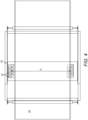
- FIG 3 shows a side view of a fabric treatment apparatus (100).
- Fabric (10) is fed (preferably as a roll) into a cleaning station (20) provided at the input end (A) of the apparatus (100).
- the cleaning station (20) as shown more clearly in Figure 8 , comprises air suction units incorporating a high pressure water supply and an adhesive coated roller (24) that removes lint or loose debris such as dust from the fabric.
- Air suction units (22) operate by vacuum effect to clean the adhesive roller and detach the loose material temporarily adhered to the roller (24) as the roller (24) rotatably contacts the fabric (10).
- the air suction units (22) remove the loose debris from the roller (24) so that the roller (24) can continue to effectively adhere debris from the fabric (10).
- the suction units (22) move along the roller (24) in a traverse direction to the direction of fabric (10) movement as shown in Figure 5 .
- the air suction units (22) therefore move in an axial direction parallel to the longitudinal axis of the roller (24) and effectively sweep the rollers (24) as they go.
- the movement of the fabric (10) through the cleaning station (20) is substantially constant or is at least continuous so that no breaks in fabric (10) movement occur. This allows the fabric (10) to be continually fed through the system (100) without interruption.
- the roller is cleaned off-line.
- the fabric (10) is fed towards a dancing roller (30), the function of which is more clearly shown in Figures 9a to 9c .
- the dancing roller (30) converts the continuous motion of the fabric (10) exiting the cleaning station (20) into intermittent motion for supply to the rest of the apparatus (100). This allows the treatment process to be integrated as one with a printing process comprising an inkjet printer.
- the dancing roller also known as an accumulator
- FIGs 9a to 9c show the dancing roller (30) in operation.
- Fabric (10) is divided into four lengths (10a,10b,10c,10d). Each length represents a time block of unity and is therefore equal in length when a constant feeding speed is used.
- the dancing roller (30) has a displaceable axis so that the dancing roller (30) axis moves with respect to the axes of the cleaning rollers.
- the dancing roller (30) moves away from adjacent rollers in a downward direction (C1) as shown in Figure 9b .
- the downward motion is simultaneous with the feeding motion and preferably operates at the same velocity. This allows one end of the first length of fabric (10a) to remain effectively stationary.
- the dancing roller (30) continues to move downwards as more fabric (10) is fed from the adjacent roller. This ensures that the fabric (10) does not slacken.
- the dancing roller (30) returns to the initial position in an upward direction (C2) as shown in Figure 9d . This allows the three lengths of fabric (10a,10b,10c) to be fed towards the next station.
- the dancing roller (30) converts continuous motion to intermittent motion so that an inkjet printer can be integrated with a pre-treatment station (20).
- the treatment station (40) comprises a moveable treatment zone (i.e. a spraying zone) is delineated by the extent of fluid spraying by the nozzles (42) on to the fabric (10).
- the spraying zone moves by an arm (46) in a transverse direction (D) across the width of the fabric (10), as shown in Figure 4 .
- the nozzles (42) spray fluid, i.e. pre-treatment chemicals onto one side of the fabric (10) only (i.e. the top side), while moving back and forth in a direction orthogonal to the direction of fabric (10) movement through the apparatus (100).
- a mechanical atomisation nozzle may be used which avoids the use of air. This allows smaller droplets to be sprayed towards the fabric (10) so that a consistent distribution of treatment fluid is transferred onto the fabric (10). During the fluid spraying stage, the fabric is held substantially constant due to the movement of the dancing roller (30) even though the fabric (10) is continuously fed through the cleaning station (20).
- the spraying zone is arranged such that the fabric (10) in contact with rollers (48) is not sprayed onto because contact with the rollers (48) can affect the integrity of the fabric (10) causing localised deformation compared to regions not in contact with the rollers (48). Therefore, only the unsupported fabric (10) is sprayed. That is, the spraying zone is arranged to act on an area between two supporting rollers.
- the duration, flow rate, pressure, volume, and average droplet size distance of the spray can be controlled in order to intimately affect the transfer or pre-treatment chemical to the fabric (10). For example, a pressure of between 50-100 bar can be used with or without a mechanical atomisation nozzle. However a pressure of between 20 and 45 bar has been found to work well and in particular around 30-35 bar.
- a high velocity spray may be used.
- the spray may be provided as a fine mist of vapour. Therefore, the penetration distance into the fabric (10) from one side of the fabric (10) can be varied. For example, a penetration level between 50-75% can be easily achieved.
- a barrier (44) is placed below the fabric (10).
- the post-treatment process may transfer chemicals onto the fabric (10) in order to make the fabric (10) water repellent.
- the treatment station (40) has the ability to control the penetration level of the treatment fluid by, for example, varying the speed of movement, the pressure, volume, flow rate of fluid ejection and the number of nozzles. This means that there is no need for a mangle to draw excess fluid out of the fabric (10), which helps to make the apparatus (100) more compact and efficient. There is also no need to submerge the fabric (10) in a fluid bath, which improves the quality control of the fluid and avoids the need to store treatment fluid in a reservoir. Furthermore, rollers are not directly exposed to the treatment chemicals during spraying.
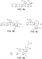
- Figure 12 shows an exemplary spray coating station (240) wherein a nozzle (250) is mounted to traverse the fabric in one direction whilst simultaneously oscillating in a back-and forth motion in a second direction.
- the nozzle is arranged to at least partially traverses the fabric (10) to cause fluid (252) to be emitted thereby coating onto the fabric (10) through gravity.
- the nozzle is caused to oscillate as shown by the arrows (254) whilst fluid is being emitted.
- the spray zone of the nozzle is increased by the oscillation, whilst also allowing the density distribution in the oscillation direction to be unevenly distributed such that fabric under the centre of the oscillation is coated with a greater density of fluid than fabric towards the edges of the spray zone.
- the fabric is arranged to move relative to the nozzle, for instance by an increment in the length direction of the fabric.
- the nozzle can then make a return traverse to coat a second and subsequent spray zone on the fabric.
- the nozzle may be arranged to step along the fabric to make multiple passes, before indexing the fabric forward.
- multiple nozzles may be provided and the fabric stepped a greater distance between each pass or passes of the nozzles.
- the nozzle (252) is selected to provide a spray of fluid having a suitable spray pattern.
- the nozzle may create a constant spray pattern across the projected spray area.
- the oscillation may be a swinging motion wherein the amount of fluid emitted at the centre of an oscillation is caused to be greater than the amount of fluid emitted towards the extremes of oscillation.
- the traverse is envisaged as moving in a linear direction across the fabric.
- the traverse When integrated with an incremental movement of fabric through an ink jet printer, the traverse would be substantially perpendicular to the lengthwise incremental movement of the fabric.
- the nozzle is mounted on an arm or other movement means that moves a nozzle mount.
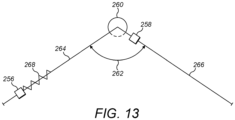
- the direction of the traverse may be at an angle to the perpendicular of the length of the fabric as shown in Figure 13 , for instance.
- the movement means moves the nozzle mount simultaneously in a two axis, such as the length and with axis of the fabric so that the nozzle moves in a non-linear direction.
- nozzles there may be two nozzles (256, 258) each of which is able to partially traverse a length of fabric, whilst simultaneously oscillating so that fluid is oscillated unevenly across the spray zone in the oscillating direction.
- the two nozzles may be arranged spaced in an oscillating direction so that two overlapping spray zones are deposited in a single traverse.
- the two nozzles may be mounted on a common nozzle mount.
- the nozzles may be arranged in line so that fluid is sprayed at a common region (260) with the traverse of one nozzle coating to one side from the common region and the traverse of the other nozzle coating to the other side.
- each nozzle of the plurality of nozzles may be arranged to coat a first respective spray zone and then to move relative to the fabric.
- the nozzles are mechanically arranged to move.
- each nozzle is arranged to coat a second respective spray zone adjacent and at least partially overlapping the respective first spray zone corresponding to that nozzle.
- Further spray zones may be created.
- the first nozzle coats in two or more successive spray zones a first area
- the second and each subsequent nozzle creates a second spray area of at least first and second spray zones. The increments being such that the first and second spray areas overlap.
- the fabric incrementally moves to provide an uncoated area under each spray nozzle.
- the multiple inline nozzles may combine to lay a linear spray zone, or, as shown in Figure 13 , the plurality of nozzles may form an inclusive angle (262) of the traverse (264) of less than 180°.
- the angle (262) may be more than 10° or more than 20° or more than 30° or more than 40° or less than 70° or less than 60° or less than 50°.
- Only one nozzle (256, 258) at a time may effect a print at the common region.
- one, or more than one nozzle may move in both directions of traverse and the fabric may be moved relative to the or each nozzle after laying a coating in one direction of traverse before effecting coating in the reverse direction.
- the traverse may be in a direction perpendicular to the length of the fabric over at least part of the extent of the traverse.
- the apparatus is suitably controllable so that the rate of traverse and rate of fluid egress from the nozzles is controllable and customisable to the fabric and fluid being coated.
- the method may comprise varying the amount of fluid being emitted during different parts of the oscillation.
- the method may comprise varying the extent of the oscillation.
- the method may comprise causing the extent of the swinging oscillation to be more than 5° or more than 10° or more than 20° or less than 60° or less than 50° or less than 40°.
- an oscillation having an angular movement of between 5° and 10° has been found to work well.
- the frequency of oscillation may be varied.
- the frequency oscillation may be between 1Hz and 100Hz, but a frequency of between 25Hz and 40Hz and in particular around 32Hz has been found to work well.
- the speed of movement in the traverse direction may be varied.
- the rate that fluid is emitted may be varied.
- the distance between the fabric and the fluid nozzle may be varied.
- each nozzle may be mounted to a nozzle mount via a pivot.
- a directly controlled motor could then be used to turn the nozzle to rotate through an angle to achieve the oscillation.
- a periodic oscillation is required wherein the rate of angular movement has a sinusoidal function.
- this is achievable with a directly controlled motor, but it has been found a more achievable system is to mechanically mount the nozzle to rotate about a pivot point through a mechanical coupling.
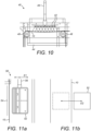
- a carriage (270) may carry the nozzle and thus cause the nozzle to effect the traverse.
- the carriage (270) includes an endless belt (272) looped around opposed wheels (274, 276) at least one of which is driven.
- the belt supports the nozzle 250 by two wheels (278, 280) that rest on the upper surface which wheels travel with the belt as the belt moves and guide the belt to drive a driving wheel 282.
- the driving wheel (282) located between the wheels (278 and 280) bears against the underside of the belt and the linear direction of the belt may be deformed slightly or the belt extends under the wheels (278, 280) and over the driving wheel (282).
- the driving wheel (282) frictionally engages with the belt and is caused to rotate as the belt moves.
- the nozzle (250) is mounted on a pivot (284).
- a reciprocating lever (286) is connected to the nozzle at a location spaced from the pivot (284).
- the lever (280) is mounted about a pivot (288).
- a further lever (290) is pivotally connected to the reciprocating lever as a pivot (292) spaced from the pivot (288).
- the further lever (290) is also connected to the driving wheel (282) at a pivot (294), radially spaced from the axis (296) of the driving wheel (282).
- a motor may be directly or indirectly connected to the pivot (284) of the fluid nozzle to effect the oscillation thereof.
- the motor may drive the fluid nozzle in alternative directions.
- the motor may be controlled to vary the extent of oscillation.
- a controller may control any one or more of the extent of oscillation, the frequency of oscillation, the speed of the traverse, the rate that fluid is emitted or the distance between the fluid nozzles and the fabric.
- the oscillation means can be achieved in a number of ways so that the nozzle tilts about an axis, typically a horizontal axis so as to divert the spray at varying angles to the vertical and therefore achieve the uneven distribution across the spay zone.
- a second configuration of the nozzle is shown. It will be appreciated that the machine may be configured to swap between previous swinging configuration and the second configuration and that this is particularly achievable by mounting the nozzle to the shaft of a stepper motor that can be directly controlled to rotate through angular movements.
- the nozzle 350 is mounted to the shaft of a motor 360.
- the motor can operate in the first configuration by swinging about a centre of oscillation, for instance the centre of oscillation is substantially vertical.
- the motor rotates the nozzle to be arranged with a principal direction angled to the vertical.
- the principal direction is indicated by arrow 351 and is the main direction that fluid is emitted from the centre of the nozzle.
- the angle to the vertical is shown as angle ⁇ .
- the angle ⁇ is around 45o.
- alternative angles are envisaged based on optimisation for the fluid and fabric.
- the angling of the nozzle causes the spray distribution to become uneven.
- the two extents of the spray pattern are indicated by lines 353 and 352. Due to the gravitational effects the spray distribution of the coating is caused to be heaviest nearest the nozzle at extent 353 and lightest furthest from the nozzle at extent 352. It has been further found that by oscillating the nozzle through short angular turns, the vibration causes the droplet pattern from the nozzle to be disturbed and therefore reduce localised hotspots within the spray pattern density.
- a more even coating can be achieved.
- Figure 15 shows a further configuration of the oscillation arrangement to cause the fluid nozzle 450 to oscillate
- a bobbin 416 is arranged in an electromagnetic system 410 that acts on the bobbin 416 to cause the bobbin to move in a side-to-side oscillating arrangement.
- the electromagnetic system comprises first 412 and second 414 electromagnets.
- the bobbin 416 is a fixed magnet. Consequently, by turning the respective first and second electromagnets on and off, the bobbin can be urged towards each electromagnet.
- a yoke arm 418 connects the bobbin 416 to the fluid nozzle 450.
- the fluid nozzle is arranged to pivot about a pivot point 460.
- the pivot is a vibration mount that resists movement by urging the nozzle back to the datum.
- the vibration mount is suitably a resilient material able to twist. One end of the material is fixed to the nozzle and the other end fixed to an anchor. The nozzle rotates by twisting the material. The natural resiliency of the material urges the nozzle back to the datum.
- the vibration mount can therefore combine with the electromagnetic forces to smooth the movement and reduce dwell or delay at the directional change.
- the fabric (10) is intermittently fed to a drying station (50) as shown in Figure 3 .
- the drying station includes means for applying heat energy.
- the emitter supported by a drying support.
- the emitter comprises a heating element.
- the emitter comprises a reflective backing.
- the emitter is chosen and tuned to emit radiation of certain range of wavelengths. Conveniently, the range is suitably chosen for the fabric and coating to be dried. In some examples, the emitter is arranged to emit predominantly a narrow range of wavelengths. In one example, the emitter is arranged to emit close to a single wavelength.
- a wavelength of more than 1.3 ⁇ m (micrometres) is chosen.
- a wavelength of 1.38 ⁇ m is selected.
- a colour temperature in a range of 2000-2200 K (Kelvin) is chosen. In some examples, the colour temperature is 2100 K.
- the emitter comprises a highly reflective backplate to increase the efficiency of the transfer of energy to the fabric.
- a highly reflective plate may be placed opposite to the emitter in a direction of emission such that, in use, fabric is located between the emitter and the highly reflective plate.
- the highly reflective plate is arranged to reflect emitted energy.
- emitted energy which has passed the fabric may thereby be redirected towards the fabric.
- the drying station comprises means for transferring mass from the fabric during the drying process.
- the drying station is configured to remove fluid, preferably moisture, resulting from the drying process.
- the amount of heat energy emitted by a drying head of the drying station is chosen for quickly drying the fabric and removing any resulting vapour. In some examples, such may be achieved within a few seconds per square meter and, in one example, one second per square meter.
- the drying station which is more clearly shown in Figures 11a and 11b , comprises a moveable infrared drier (52).
- a length of fabric (10) placed between the infrared drier (52) and a heat shield (54), such as a reflector is heated by the thermal energy transferred by the infrared radiation.
- the region of thermal energy emitted from the infrared drier (52) is the drying zone.
- the proximity of the infrared drier (52) to the fabric can be varied in order to affect the speed of drying and/or heating.
- a distance of between 100-200mm can be used when the infrared drier (52) is static or a closer distance of between 25-100mm, or preferably 10-50mm, can be used when there is relative movement between the infrared drier (52) are the fabric (i.e. the infrared driver (52) is continuously moving).
- the use of an infrared drier (52) allows the drying means to be turned on and off as required because the infrared drier (52) can warm up quickly without detrimental performance effects.
- the drying zone can be well controlled. For example, the speed of the drier (52) relative to the fabric (10) can be varied as well as the distance between the drier (52) and the fabric (10).
- a moveable arm (56) connected to the infrared drier (52) is configured to move relative to the fabric (10) when the fabric (10) is held in position.
- the infrared drier (52) may move towards or away from the fabric (10) in a first direction (E1) and side-to-side in a second direction (E2), substantially orthogonal to the first direction (E1).
- the infrared drier (52) may move beyond the edges of the fabric (10). This helps to evenly spread the distribution of heat and avoid scorching of the fabric (10).
- the sideways movement of the infrared heater (52), i.e. in the second direction, is preferably timed according to the movement of the dancing roller (30) and the spraying of the fabric (10).
- the fabric can be held in position in a stop-start nature to allow sections of the fabric (10) to be acted on at once.
- the drier (52) may rotate away from the fabric (10) such that the drying rate of the fabric (10) is reduced even if the drier (52) remains on.
- air movement over the fabric (10) may be used by blowing or suction force in order to encourage the removal of fluid particles from the fabric (10).
- the infrared drier (52) may move in an up and down direction, i.e. a third direction, which is substantially orthogonal to the first and second directions. This ads further configurability depending on the type of drying required.
- the fabric is sent through a printing station, which may be a separate station.
- a printing station which may be a separate station.
- the printing nozzles acting on the fabric (10) move across the fabric (10) in a side-to-side motion.
- the fabric (10) is held substantially stationary in order to allow the ink to be passed onto the fabric (10) in a linear fashion.
- An array of nozzles arranged in a column i.e. along the fabric (10) may be used in order to concurrently move across the fabric (10) and act on a larger surface area.
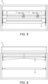
- Figures 5 and 6 show the front and back views of the apparatus, respectively.
- the rollers (12) are elongate to reduce inertial load and accommodate fabric (10) that may be at least 3m in width.
- the rollers (12) each has a rotation axis which may be powered or unpowered. Therefore, some rollers (12) may be used to drive the fabric (10) forward or may freewheel such that they spin freely.
- the axes of the rollers (12) are shown attached to framework (14) that provides the structure of the apparatus (100).
- Figure 7 shows a flow diagram of the apparatus (100) as a whole.
- the apparatus (100) is configured to receive a roll of fabric (10) and input the fabric (10) as a continuous length.
- the fabric is continuously fed to a cleaning stage (210), where debris is removed from the fabric (10) from at least one side of the fabric (10).
- the continuous motion of the fabric (10) movement is then changed into intermittent motion. Therefore sections of the fabric (10) are then fed to a spraying stage (220), whereby the fabric (10) is coated from at least one side with a pre-treatment fluid.
- the amount of penetration is controlled in order to embed the fabric (10) accordingly.
- sections of the fabric (10) are intermittently fed to a drying station (230), where the fabric (10) is dried in and the pre-treatment fluid is retained by the fabric (10).
- This drying action may extend to a heating action in order to prepare the fabric (10) for printing by inkjet.
- the fabric (10) is fed to a printing stage (240), whereby the fabric (10) is printed on by ink. This allows graphics to be applied to the pre-treated and dried fabric (10) before being outputted (250) for delivery or storage.
- the apparatus minimises changeover disruption so that a different pre-treatment chemical can be quickly and more conveniently changed.
- the extent of chemical penetration into the fabric can be controlled by the use of nozzles to provide a more flexible method of coating the fabric.
- the moveable drier and/or improved transient nature of the drier prevents the fabric being scorched and allows the drying process to be unaffected when stationary.
- the moveable drying and/or spraying zone allows the fabric to be held in position.
- the apparatus provides greater customisation and flexibility for improved efficiency and reduced downtime.
- each various part may also be used in isolation and provide benefits to known drying or coating systems.
- the material treatment station can be used in isolation to provide advantages over known padding and stenter processes. For instance, it has been found that by spraying the treatment a lower amount of chemicals need to be used in the treatment. That is, in the padding and stenter process, the fabric absorbs more treatment fluid than it needs, Whereas by spraying a more controlled delivery process is achieved. As such, not only can the coating be completed with less chemicals, but because less chemicals are used, different chemicals can be used.
- the padding and stenter process uses a relatively dilute treatment, for instance around 80% water. In contrast, a less dilute treatment fluid can be used in the spray treatment process herein described because the treatment process is more controlled. As such, it has been found that significant energy savings can be made due less energy being required to evaporate the water from the treatment from the substrate.
- the method of coating and the spray coating apparatus provides a more uniform distribution of fluid, particularly at the joins between successive spray zones.
- a further advantage is that the printing on the fabric is effected at a faster speed.
Landscapes
- Engineering & Computer Science (AREA)
- Textile Engineering (AREA)
- Chemical & Material Sciences (AREA)
- Chemical Kinetics & Catalysis (AREA)
- General Chemical & Material Sciences (AREA)
- Materials Engineering (AREA)
- Treatment Of Fiber Materials (AREA)
Claims (13)
- Verfahren zum Beschichten eines Gewebes (10) mit einer gleichmäßigen Beschichtungsverteilung eines Fluids, wobei das Verfahren umfasst:Bewirken, dass mindestens eine Düse (250, 350) die Länge eines Gewebes (10) zumindest teilweise in einer ersten Richtung abfährt, während gleichzeitig Fluid emittiert und die mindestens eine Düse (250, 350) geschwenkt wird, um dadurch das Gewebe (10) in einer ersten Sprühzone ungleichmäßig zu beschichten.anschließend Bewirken einer relativen Bewegung des Gewebes (10) und der mindestens einen Düse (250, 350) in Längsrichtung des Gewebes (10), wobei die erste Richtung einen Winkel zur Längsrichtung des Gewebes (10) bildet; undanschließend Bewirken, dass die mindestens eine Düse (250, 350) eine zweite Länge des Gewebes (10) in einer zweiten Richtung abfährt, während gleichzeitig Fluid emittiert und die mindestens eine Düse (250, 350) pendelt, um dadurch das Gewebe (10) in einer zweiten Sprühzone ungleichmäßig zu beschichten,wobei die erste Richtung und die zweite Richtung entgegengesetzte Richtungen sind, undjede Sprühzone eine andere Sprühzone zumindest teilweise überlappt.
- Verfahren nach Anspruch 1, wobei das Verfahren das Bewirken einer Pendelbewegung der mindestens einen Düse (250, 350) umfasst, sodass die Sprühzone eine stärkste Fluidverteilung in der Mitte der Pendelbewegung und eine leichteste Fluidverteilung an den zwei Enden der Pendelbewegung erfährt.
- Verfahren nach Anspruch 1, wobei das Verfahren umfasst, dass die mindestens eine Düse (250, 350) so angeordnet wird, dass sie eine primäre Fluidaustrittsrichtung aufweist, die zur Vertikalen geneigt ist, sodass die Sprühzone dadurch veranlasst wird, die schwerste Fluidverteilung nahe der mindestens einen Düse (250, 350) und die leichteste Fluidverteilung am weitesten von der mindestens einen Düse (250, 350) entfernt aufzuweisen.
- Verfahren nach einem der vorhergehenden Ansprüche, wobei zumindest ein Teil der Abfahrbewegung in einer Richtung rechtwinklig zur Länge des Gewebes (10) über zumindest einen Teil des Abfahrweges ausgeführt wird.
- Verfahren nach einem der vorhergehenden Ansprüche, wobei die Menge des während der verschiedenen Teile der Pendelbewegung emittierten Fluids verändert wird.
- Sprühbeschichtungsvorrichtung (240) zum Auftragen einer gleichmäßigen Beschichtungsverteilung eines Fluids auf ein Gewebe (10), wobei die Sprühbeschichtungsvorrichtung (240) umfasst:einen Schlitten (270), der eine Düse (250, 350) trägt, wobei der Schlitten (270) dazu angeordnet ist, die Düse (250) in einer ersten Richtung und in einer zweiten Richtung zu tragen, um das Gewebe (10) zumindest teilweise zu abzufahren, wobei die erste Richtung und die zweite Richtung entgegengesetzte Richtungen sind; undBewegungsmittel, die dazu ausgelegt sind, das Gewebe (10) relativ zur Düse (250, 350) in Längsrichtung des Gewebes (10) zu bewegen, wobei die erste Richtung einen Winkel zur Längsrichtung des Gewebes (10) bildet;dadurch gekennzeichnet, dass:die Düse (250, 350) mit einem Pendelaggregat (360) an dem Schlitten (270) befestigt ist, das dazu eingerichtet ist, die Düse (250, 350) in einer Pendelrichtung pendeln zu lassen; sodass die Düse (250) beim Abfahren in der ersten Richtung eine ungleichmäßige Fluidverteilung in einer ersten Sprühzone und beim Abfahren in der zweiten Richtung eine ungleichmäßige Fluidverteilung in einer zweiten Sprühzone emittiert; undumfassend eine Fluidzufuhreinrichtung zum Zuführen von Fluid zu der Düse (250, 350), sodass Fluid aus der Düse (250, 350) gesprüht wird, während sie sich gleichzeitig bewegt und pendelt, sodass jede Sprühzone eine andere Sprühzone zumindest teilweise überlappt.
- Sprühbeschichtungsvorrichtung (240) nach Anspruch 6, mit einer Steuervorrichtung, die dazu eingerichtet ist, im Betrieb das Pendelmaß des Pendelaggregats (360), die Pendelfrequenz des Pendelaggregats (360), die Bewegungsgeschwindigkeit des Schlittens (270), die Menge der durch die Düse (250, 350) emittierten Fluids oder den Abstand zwischen der Düse (250, 350) und einem Gewebe (10) zu steuern.
- Sprühbeschichtungsvorrichtung (240) nach Anspruch 6, bei der die Düse (250, 350) drehbar an dem Schlitten (270) angebracht ist.
- Sprühbeschichtungsvorrichtung (240) nach Anspruch 8, bei der das Pendelaggregat (360) einen Pendelhebel (286) enthält, der mit der Düse (250, 350) an einer Stelle verbunden ist, die von der Schwenkverbindung der Düse (250, 350) beabstandet ist.
- Sprühbeschichtungsvorrichtung (240) nach Anspruch 9, bei der der Pendelhebel (286) schwenkbar an der Düse (250, 350) angebracht ist und der Hebel im Gebrauch durch einen weiteren Hebel (290), der schwenkbar mit dem Pendelhebel (286) verbunden ist, zum Pendeln veranlasst wird, wobei der weitere Hebel (290) ebenfalls schwenkbar mit einem Drehelement in einem Abstand von der Schwenkverbindung des Drehelements verbunden ist.
- Sprühvorrichtung nach Anspruch 10, wobei das Drehelement im Gebrauch durch Reibungseingriff mit einem Riemen (272) des Schlittens (270) in Drehung versetzt wird, wobei der Riemen (272) die Abfahrbewegung der Düse (250, 350) bewirkt.
- Sprühbeschichtungsvorrichtung (240) nach Anspruch 8, mit einem Motor (360), der dazu eingerichtet ist, im Betrieb eine Pendelbewegung der Düse (250, 350) zu bewirken.
- Sprühbeschichtungsvorrichtung (240) nach einem der Ansprüche 6 bis 12, mit mindestens zwei Düsen (250), die jeweils durch einen Schlitten (270) getragen und dazu veranlasst werden, das Gewebe (10) zumindest teilweise in einer Richtung abzufahren, und wobei jede Düse (250, 350) ein Pendelaggregat (360) aufweist, das dazu eingerichtet ist, beim gleichzeitigen Abfahren und Pendeln ein Fluid zu emittieren.
Applications Claiming Priority (2)
| Application Number | Priority Date | Filing Date | Title |
|---|---|---|---|
| GB1703599.9A GB2560327B (en) | 2017-03-07 | 2017-03-07 | Apparatus and method for spray treating fabric |
| PCT/GB2018/050241 WO2018162872A1 (en) | 2017-03-07 | 2018-01-26 | Apparatus and method for spray treating fabric |
Publications (3)
| Publication Number | Publication Date |
|---|---|
| EP3592893A1 EP3592893A1 (de) | 2020-01-15 |
| EP3592893B1 true EP3592893B1 (de) | 2024-09-11 |
| EP3592893C0 EP3592893C0 (de) | 2024-09-11 |
Family
ID=58543995
Family Applications (1)
| Application Number | Title | Priority Date | Filing Date |
|---|---|---|---|
| EP18702551.5A Active EP3592893B1 (de) | 2017-03-07 | 2018-01-26 | Vorrichtung und verfahren zur sprühbehandlung von gewebe |
Country Status (5)
| Country | Link |
|---|---|
| US (1) | US11472213B2 (de) |
| EP (1) | EP3592893B1 (de) |
| CN (1) | CN110382763B (de) |
| GB (1) | GB2560327B (de) |
| WO (1) | WO2018162872A1 (de) |
Families Citing this family (7)
| Publication number | Priority date | Publication date | Assignee | Title |
|---|---|---|---|---|
| GB2560327B (en) | 2017-03-07 | 2019-04-17 | Technijet Digital Ltd | Apparatus and method for spray treating fabric |
| US10940501B2 (en) | 2018-01-30 | 2021-03-09 | Ford Motor Company | Composite ultrasonic material applicators with individually addressable micro-applicators and methods of use thereof |
| US11504980B2 (en) * | 2018-12-13 | 2022-11-22 | ColDesi, Inc. | Apparatus and methods for processing digitally printed textile materials |
| CN114635242A (zh) * | 2022-03-23 | 2022-06-17 | 杭州职业技术学院 | 一种聚乳酸纤维面料生产加工用染色装置 |
| NL2036315B1 (nl) * | 2023-11-20 | 2025-06-02 | Printable B V | Inrichting en werkwijze voor het bedekken van een substraat |
| CN117565562B (zh) * | 2023-11-23 | 2025-06-24 | 武汉市新发工艺五金钢模工具有限责任公司 | 一种点阵喷印组件、单元和设备 |
| CN120486060B (zh) * | 2025-07-17 | 2025-11-14 | 中国人民解放军中部战区总医院 | 一种智能电控喷涂装置及纳米纤维骨修复膜的制备方法 |
Family Cites Families (15)
| Publication number | Priority date | Publication date | Assignee | Title |
|---|---|---|---|---|
| GB210361A (en) * | 1923-07-09 | 1924-01-31 | Alphonse Emile Verge | Improvements in or relating to colour-projecting machines |
| US2770216A (en) * | 1955-08-10 | 1956-11-13 | Alexander Smith Inc | Spraying apparatus for web material |
| US4156041A (en) * | 1975-11-27 | 1979-05-22 | Imperial Chemical Industries Limited | Deposition of polyurethane foam-forming liquid reaction mixture |
| GB1543729A (en) * | 1975-11-27 | 1979-04-04 | Ici Ltd | Apparatus and process for depositing liquid reaction mixtures onto continuously moving sheet material |
| DE2928563A1 (de) | 1979-07-14 | 1981-01-29 | Vepa Ag | Vorrichtung zum antreiben einer beschichtungseinrichtung |
| US4282729A (en) | 1979-09-28 | 1981-08-11 | United Merchants And Manufacturers, Inc. | Foam random dyeing system |
| JPH06262478A (ja) * | 1993-03-10 | 1994-09-20 | Enshu Ltd | ノズルの噴射方向自動制御装置 |
| US6036123A (en) * | 1999-01-29 | 2000-03-14 | West; Richard A. | Apparatus for applying foam material to a substrate |
| DE10232984A1 (de) * | 2002-07-19 | 2004-02-05 | Steag Hamatech Ag | Düsenanordnung zum Aufbringen einer Flüssigkeit auf ein Substrat |
| ATE425287T1 (de) | 2003-09-22 | 2009-03-15 | Ten Cate Advanced Textiles Bv | Verfahren und vorrichtung zur digitalen verbesserung von textil |
| US7118629B2 (en) * | 2004-07-06 | 2006-10-10 | James W Davidson | Apparatus for applying a coating to a roof or other substrate |
| KR100677579B1 (ko) * | 2005-04-26 | 2007-02-02 | 삼성전자주식회사 | 잉크젯 화상형성장치 |
| ES2351944T3 (es) * | 2007-10-31 | 2011-02-14 | Xennia Holland Bv | Disposición de cabezales de impresión y procedimiento para la deposición de una sustancia. |
| GB0907362D0 (en) * | 2009-04-29 | 2009-06-10 | Ten Cate Itex B V | Print carriage |
| GB2560327B (en) | 2017-03-07 | 2019-04-17 | Technijet Digital Ltd | Apparatus and method for spray treating fabric |
-
2017
- 2017-03-07 GB GB1703599.9A patent/GB2560327B/en active Active
-
2018
- 2018-01-26 US US16/491,327 patent/US11472213B2/en active Active
- 2018-01-26 EP EP18702551.5A patent/EP3592893B1/de active Active
- 2018-01-26 WO PCT/GB2018/050241 patent/WO2018162872A1/en not_active Ceased
- 2018-01-26 CN CN201880016608.XA patent/CN110382763B/zh active Active
Also Published As
| Publication number | Publication date |
|---|---|
| CN110382763A (zh) | 2019-10-25 |
| WO2018162872A1 (en) | 2018-09-13 |
| EP3592893A1 (de) | 2020-01-15 |
| US20200016913A1 (en) | 2020-01-16 |
| CN110382763B (zh) | 2022-06-10 |
| EP3592893C0 (de) | 2024-09-11 |
| GB201703599D0 (en) | 2017-04-19 |
| GB2560327A (en) | 2018-09-12 |
| US11472213B2 (en) | 2022-10-18 |
| GB2560327B (en) | 2019-04-17 |
Similar Documents
| Publication | Publication Date | Title |
|---|---|---|
| EP3592893B1 (de) | Vorrichtung und verfahren zur sprühbehandlung von gewebe | |
| JP2004058031A (ja) | 液体吹付付与装置、それを使用した液体の吹き付け付与方法、及び薬液 | |
| CN113840953B (zh) | 数字化纺织品印刷的方法和设备 | |
| JP2013078748A (ja) | 塗布方法および塗布装置 | |
| CN108351168B (zh) | 用于处理织物的设备和方法 | |
| CN201099050Y (zh) | 一种同步双面数码喷绘机 | |
| KR102131953B1 (ko) | 코팅액 도포장치 | |
| JP6251246B2 (ja) | フレキソ・コーティング装置のオンデマンド動作 | |
| JP6720659B2 (ja) | 基材の液切り装置 | |
| US20210107298A1 (en) | Liquid ejecting device | |
| KR101603605B1 (ko) | 인쇄장치 및 인쇄방법 | |
| JP2017019622A (ja) | 液体吐出装置、及び搬送ベルト洗浄方法 | |
| CN116638869A (zh) | 印刷系统以及处理装置 | |
| JP3593870B2 (ja) | 抄紙機のカンバス汚染防止方法及びそのための抄紙機のドライパート | |
| CA3226028A1 (en) | Apparatus and method for increasing colourfastness | |
| KR100762750B1 (ko) | 코팅제 도포량 자동조절이 가능한 원단 코팅기 | |
| JP5504573B2 (ja) | 塗布液の塗布方法 | |
| JP7782300B2 (ja) | 印刷システム及び処理装置 | |
| WO2009136429A1 (ja) | マスキング装置およびそれを備えたプラズマディスプレイパネル製造システム | |
| JP4785376B2 (ja) | 塗布装置および塗布方法 | |
| JP3336265B2 (ja) | 画像形成装置 | |
| JP2014034141A (ja) | 液滴噴射装置 | |
| KR200277109Y1 (ko) | 컬러염료 분사장치 | |
| JP4982836B2 (ja) | ラミネート装置 | |
| JP2017105045A (ja) | 液体吐出装置 |
Legal Events
| Date | Code | Title | Description |
|---|---|---|---|
| STAA | Information on the status of an ep patent application or granted ep patent |
Free format text: STATUS: UNKNOWN |
|
| STAA | Information on the status of an ep patent application or granted ep patent |
Free format text: STATUS: THE INTERNATIONAL PUBLICATION HAS BEEN MADE |
|
| PUAI | Public reference made under article 153(3) epc to a published international application that has entered the european phase |
Free format text: ORIGINAL CODE: 0009012 |
|
| STAA | Information on the status of an ep patent application or granted ep patent |
Free format text: STATUS: REQUEST FOR EXAMINATION WAS MADE |
|
| 17P | Request for examination filed |
Effective date: 20190902 |
|
| AK | Designated contracting states |
Kind code of ref document: A1 Designated state(s): AL AT BE BG CH CY CZ DE DK EE ES FI FR GB GR HR HU IE IS IT LI LT LU LV MC MK MT NL NO PL PT RO RS SE SI SK SM TR |
|
| AX | Request for extension of the european patent |
Extension state: BA ME |
|
| DAV | Request for validation of the european patent (deleted) | ||
| DAX | Request for extension of the european patent (deleted) | ||
| STAA | Information on the status of an ep patent application or granted ep patent |
Free format text: STATUS: EXAMINATION IS IN PROGRESS |
|
| 17Q | First examination report despatched |
Effective date: 20210702 |
|
| RAP1 | Party data changed (applicant data changed or rights of an application transferred) |
Owner name: DURST GROUP AG |
|
| 111L | Licence recorded |
Designated state(s): AL AT BE BG CH CY CZ DE DK EE ES FI FR GB GR HR HU IE IS IT LT LU LV MC MK MT NL NO PL PT RO RS SE SI SK SM TR Name of requester: TECHNIJET LTD, GB Effective date: 20220208 |
|
| GRAP | Despatch of communication of intention to grant a patent |
Free format text: ORIGINAL CODE: EPIDOSNIGR1 |
|
| STAA | Information on the status of an ep patent application or granted ep patent |
Free format text: STATUS: GRANT OF PATENT IS INTENDED |
|
| INTG | Intention to grant announced |
Effective date: 20240410 |
|
| GRAS | Grant fee paid |
Free format text: ORIGINAL CODE: EPIDOSNIGR3 |
|
| GRAA | (expected) grant |
Free format text: ORIGINAL CODE: 0009210 |
|
| STAA | Information on the status of an ep patent application or granted ep patent |
Free format text: STATUS: THE PATENT HAS BEEN GRANTED |
|
| 111L | Licence recorded |
Designated state(s): AL AT BE BG CH CY CZ DE DK EE ES FI FR GB GR HR HU IE IS IT LT LU LV MC MK MT NL NO PL PT RO RS SE SI SK SM TR Name of requester: TECHNIJET LTD, GB Effective date: 20220208 |
|
| AK | Designated contracting states |
Kind code of ref document: B1 Designated state(s): AL AT BE BG CH CY CZ DE DK EE ES FI FR GB GR HR HU IE IS IT LI LT LU LV MC MK MT NL NO PL PT RO RS SE SI SK SM TR |
|
| REG | Reference to a national code |
Ref country code: GB Ref legal event code: FG4D |
|
| REG | Reference to a national code |
Ref country code: CH Ref legal event code: EP |
|
| REG | Reference to a national code |
Ref country code: DE Ref legal event code: R096 Ref document number: 602018074203 Country of ref document: DE |
|
| REG | Reference to a national code |
Ref country code: IE Ref legal event code: FG4D |
|
| U01 | Request for unitary effect filed |
Effective date: 20240921 |
|
| U07 | Unitary effect registered |
Designated state(s): AT BE BG DE DK EE FI FR IT LT LU LV MT NL PT RO SE SI Effective date: 20241015 |
|
| PG25 | Lapsed in a contracting state [announced via postgrant information from national office to epo] |
Ref country code: NO Free format text: LAPSE BECAUSE OF FAILURE TO SUBMIT A TRANSLATION OF THE DESCRIPTION OR TO PAY THE FEE WITHIN THE PRESCRIBED TIME-LIMIT Effective date: 20241211 |
|
| PG25 | Lapsed in a contracting state [announced via postgrant information from national office to epo] |
Ref country code: GR Free format text: LAPSE BECAUSE OF FAILURE TO SUBMIT A TRANSLATION OF THE DESCRIPTION OR TO PAY THE FEE WITHIN THE PRESCRIBED TIME-LIMIT Effective date: 20241212 |
|
| PG25 | Lapsed in a contracting state [announced via postgrant information from national office to epo] |
Ref country code: HR Free format text: LAPSE BECAUSE OF FAILURE TO SUBMIT A TRANSLATION OF THE DESCRIPTION OR TO PAY THE FEE WITHIN THE PRESCRIBED TIME-LIMIT Effective date: 20240911 |
|
| PG25 | Lapsed in a contracting state [announced via postgrant information from national office to epo] |
Ref country code: ES Free format text: LAPSE BECAUSE OF FAILURE TO SUBMIT A TRANSLATION OF THE DESCRIPTION OR TO PAY THE FEE WITHIN THE PRESCRIBED TIME-LIMIT Effective date: 20240911 Ref country code: RS Free format text: LAPSE BECAUSE OF FAILURE TO SUBMIT A TRANSLATION OF THE DESCRIPTION OR TO PAY THE FEE WITHIN THE PRESCRIBED TIME-LIMIT Effective date: 20241211 |
|
| PG25 | Lapsed in a contracting state [announced via postgrant information from national office to epo] |
Ref country code: RS Free format text: LAPSE BECAUSE OF FAILURE TO SUBMIT A TRANSLATION OF THE DESCRIPTION OR TO PAY THE FEE WITHIN THE PRESCRIBED TIME-LIMIT Effective date: 20241211 Ref country code: NO Free format text: LAPSE BECAUSE OF FAILURE TO SUBMIT A TRANSLATION OF THE DESCRIPTION OR TO PAY THE FEE WITHIN THE PRESCRIBED TIME-LIMIT Effective date: 20241211 Ref country code: HR Free format text: LAPSE BECAUSE OF FAILURE TO SUBMIT A TRANSLATION OF THE DESCRIPTION OR TO PAY THE FEE WITHIN THE PRESCRIBED TIME-LIMIT Effective date: 20240911 Ref country code: GR Free format text: LAPSE BECAUSE OF FAILURE TO SUBMIT A TRANSLATION OF THE DESCRIPTION OR TO PAY THE FEE WITHIN THE PRESCRIBED TIME-LIMIT Effective date: 20241212 Ref country code: ES Free format text: LAPSE BECAUSE OF FAILURE TO SUBMIT A TRANSLATION OF THE DESCRIPTION OR TO PAY THE FEE WITHIN THE PRESCRIBED TIME-LIMIT Effective date: 20240911 |
|
| U20 | Renewal fee for the european patent with unitary effect paid |
Year of fee payment: 8 Effective date: 20250127 |
|
| PG25 | Lapsed in a contracting state [announced via postgrant information from national office to epo] |
Ref country code: IS Free format text: LAPSE BECAUSE OF FAILURE TO SUBMIT A TRANSLATION OF THE DESCRIPTION OR TO PAY THE FEE WITHIN THE PRESCRIBED TIME-LIMIT Effective date: 20250111 |
|
| PG25 | Lapsed in a contracting state [announced via postgrant information from national office to epo] |
Ref country code: SM Free format text: LAPSE BECAUSE OF FAILURE TO SUBMIT A TRANSLATION OF THE DESCRIPTION OR TO PAY THE FEE WITHIN THE PRESCRIBED TIME-LIMIT Effective date: 20240911 |
|
| PG25 | Lapsed in a contracting state [announced via postgrant information from national office to epo] |
Ref country code: CZ Free format text: LAPSE BECAUSE OF FAILURE TO SUBMIT A TRANSLATION OF THE DESCRIPTION OR TO PAY THE FEE WITHIN THE PRESCRIBED TIME-LIMIT Effective date: 20240911 Ref country code: PL Free format text: LAPSE BECAUSE OF FAILURE TO SUBMIT A TRANSLATION OF THE DESCRIPTION OR TO PAY THE FEE WITHIN THE PRESCRIBED TIME-LIMIT Effective date: 20240911 |
|
| PG25 | Lapsed in a contracting state [announced via postgrant information from national office to epo] |
Ref country code: SK Free format text: LAPSE BECAUSE OF FAILURE TO SUBMIT A TRANSLATION OF THE DESCRIPTION OR TO PAY THE FEE WITHIN THE PRESCRIBED TIME-LIMIT Effective date: 20240911 |
|
| PLBE | No opposition filed within time limit |
Free format text: ORIGINAL CODE: 0009261 |
|
| STAA | Information on the status of an ep patent application or granted ep patent |
Free format text: STATUS: NO OPPOSITION FILED WITHIN TIME LIMIT |
|
| 26N | No opposition filed |
Effective date: 20250612 |
|
| REG | Reference to a national code |
Ref country code: CH Ref legal event code: PL |
|
| PG25 | Lapsed in a contracting state [announced via postgrant information from national office to epo] |
Ref country code: MC Free format text: LAPSE BECAUSE OF FAILURE TO SUBMIT A TRANSLATION OF THE DESCRIPTION OR TO PAY THE FEE WITHIN THE PRESCRIBED TIME-LIMIT Effective date: 20240911 |
|
| GBPC | Gb: european patent ceased through non-payment of renewal fee |
Effective date: 20250126 |
|
| PG25 | Lapsed in a contracting state [announced via postgrant information from national office to epo] |
Ref country code: GB Free format text: LAPSE BECAUSE OF NON-PAYMENT OF DUE FEES Effective date: 20250126 |
|
| PG25 | Lapsed in a contracting state [announced via postgrant information from national office to epo] |
Ref country code: CH Free format text: LAPSE BECAUSE OF NON-PAYMENT OF DUE FEES Effective date: 20250131 |