EP3589861B1 - Membrane et palier à amortissement hydraulique - Google Patents
Membrane et palier à amortissement hydraulique Download PDFInfo
- Publication number
- EP3589861B1 EP3589861B1 EP18712534.9A EP18712534A EP3589861B1 EP 3589861 B1 EP3589861 B1 EP 3589861B1 EP 18712534 A EP18712534 A EP 18712534A EP 3589861 B1 EP3589861 B1 EP 3589861B1
- Authority
- EP
- European Patent Office
- Prior art keywords
- elastomer body
- bearing
- leg
- core
- membrane
- Prior art date
- Legal status (The legal status is an assumption and is not a legal conclusion. Google has not performed a legal analysis and makes no representation as to the accuracy of the status listed.)
- Active
Links
- 238000013016 damping Methods 0.000 title claims description 63
- 239000012528 membrane Substances 0.000 title description 94
- 229920001971 elastomer Polymers 0.000 claims description 119
- 239000000806 elastomer Substances 0.000 claims description 115
- 239000012530 fluid Substances 0.000 claims description 40
- 210000004379 membrane Anatomy 0.000 description 98
- 230000036316 preload Effects 0.000 description 13
- 238000005086 pumping Methods 0.000 description 10
- 230000000694 effects Effects 0.000 description 9
- 239000000463 material Substances 0.000 description 7
- 239000002184 metal Substances 0.000 description 6
- 239000004033 plastic Substances 0.000 description 6
- 238000010521 absorption reaction Methods 0.000 description 5
- 230000003068 static effect Effects 0.000 description 5
- 238000009434 installation Methods 0.000 description 4
- 238000005096 rolling process Methods 0.000 description 3
- 230000008961 swelling Effects 0.000 description 3
- 238000004073 vulcanization Methods 0.000 description 3
- 238000005452 bending Methods 0.000 description 2
- 239000013536 elastomeric material Substances 0.000 description 2
- 125000001145 hydrido group Chemical group *[H] 0.000 description 2
- 210000003734 kidney Anatomy 0.000 description 2
- 238000000034 method Methods 0.000 description 2
- 238000003825 pressing Methods 0.000 description 2
- 238000007789 sealing Methods 0.000 description 2
- 230000008719 thickening Effects 0.000 description 2
- 238000003466 welding Methods 0.000 description 2
- 230000005540 biological transmission Effects 0.000 description 1
- 230000001419 dependent effect Effects 0.000 description 1
- ZZUFCTLCJUWOSV-UHFFFAOYSA-N furosemide Chemical compound C1=C(Cl)C(S(=O)(=O)N)=CC(C(O)=O)=C1NCC1=CC=CO1 ZZUFCTLCJUWOSV-UHFFFAOYSA-N 0.000 description 1
- 230000000149 penetrating effect Effects 0.000 description 1
- 230000000284 resting effect Effects 0.000 description 1
Images

Classifications
-
- F—MECHANICAL ENGINEERING; LIGHTING; HEATING; WEAPONS; BLASTING
- F16—ENGINEERING ELEMENTS AND UNITS; GENERAL MEASURES FOR PRODUCING AND MAINTAINING EFFECTIVE FUNCTIONING OF MACHINES OR INSTALLATIONS; THERMAL INSULATION IN GENERAL
- F16F—SPRINGS; SHOCK-ABSORBERS; MEANS FOR DAMPING VIBRATION
- F16F13/00—Units comprising springs of the non-fluid type as well as vibration-dampers, shock-absorbers, or fluid springs
- F16F13/04—Units comprising springs of the non-fluid type as well as vibration-dampers, shock-absorbers, or fluid springs comprising both a plastics spring and a damper, e.g. a friction damper
- F16F13/06—Units comprising springs of the non-fluid type as well as vibration-dampers, shock-absorbers, or fluid springs comprising both a plastics spring and a damper, e.g. a friction damper the damper being a fluid damper, e.g. the plastics spring not forming a part of the wall of the fluid chamber of the damper
- F16F13/08—Units comprising springs of the non-fluid type as well as vibration-dampers, shock-absorbers, or fluid springs comprising both a plastics spring and a damper, e.g. a friction damper the damper being a fluid damper, e.g. the plastics spring not forming a part of the wall of the fluid chamber of the damper the plastics spring forming at least a part of the wall of the fluid chamber of the damper
- F16F13/10—Units comprising springs of the non-fluid type as well as vibration-dampers, shock-absorbers, or fluid springs comprising both a plastics spring and a damper, e.g. a friction damper the damper being a fluid damper, e.g. the plastics spring not forming a part of the wall of the fluid chamber of the damper the plastics spring forming at least a part of the wall of the fluid chamber of the damper the wall being at least in part formed by a flexible membrane or the like
- F16F13/105—Units comprising springs of the non-fluid type as well as vibration-dampers, shock-absorbers, or fluid springs comprising both a plastics spring and a damper, e.g. a friction damper the damper being a fluid damper, e.g. the plastics spring not forming a part of the wall of the fluid chamber of the damper the plastics spring forming at least a part of the wall of the fluid chamber of the damper the wall being at least in part formed by a flexible membrane or the like characterised by features of partitions between two working chambers
- F16F13/106—Design of constituent elastomeric parts, e.g. decoupling valve elements, or of immediate abutments therefor, e.g. cages
-
- F—MECHANICAL ENGINEERING; LIGHTING; HEATING; WEAPONS; BLASTING
- F16—ENGINEERING ELEMENTS AND UNITS; GENERAL MEASURES FOR PRODUCING AND MAINTAINING EFFECTIVE FUNCTIONING OF MACHINES OR INSTALLATIONS; THERMAL INSULATION IN GENERAL
- F16F—SPRINGS; SHOCK-ABSORBERS; MEANS FOR DAMPING VIBRATION
- F16F13/00—Units comprising springs of the non-fluid type as well as vibration-dampers, shock-absorbers, or fluid springs
- F16F13/04—Units comprising springs of the non-fluid type as well as vibration-dampers, shock-absorbers, or fluid springs comprising both a plastics spring and a damper, e.g. a friction damper
- F16F13/06—Units comprising springs of the non-fluid type as well as vibration-dampers, shock-absorbers, or fluid springs comprising both a plastics spring and a damper, e.g. a friction damper the damper being a fluid damper, e.g. the plastics spring not forming a part of the wall of the fluid chamber of the damper
- F16F13/08—Units comprising springs of the non-fluid type as well as vibration-dampers, shock-absorbers, or fluid springs comprising both a plastics spring and a damper, e.g. a friction damper the damper being a fluid damper, e.g. the plastics spring not forming a part of the wall of the fluid chamber of the damper the plastics spring forming at least a part of the wall of the fluid chamber of the damper
- F16F13/14—Units of the bushing type, i.e. loaded predominantly radially
- F16F13/1427—Units of the bushing type, i.e. loaded predominantly radially characterised by features of flexible walls of equilibration chambers; decoupling or self-tuning means
-
- B—PERFORMING OPERATIONS; TRANSPORTING
- B60—VEHICLES IN GENERAL
- B60G—VEHICLE SUSPENSION ARRANGEMENTS
- B60G2204/00—Indexing codes related to suspensions per se or to auxiliary parts
- B60G2204/10—Mounting of suspension elements
- B60G2204/14—Mounting of suspension arms
- B60G2204/143—Mounting of suspension arms on the vehicle body or chassis
-
- B—PERFORMING OPERATIONS; TRANSPORTING
- B60—VEHICLES IN GENERAL
- B60G—VEHICLE SUSPENSION ARRANGEMENTS
- B60G2204/00—Indexing codes related to suspensions per se or to auxiliary parts
- B60G2204/40—Auxiliary suspension parts; Adjustment of suspensions
- B60G2204/41—Elastic mounts, e.g. bushings
- B60G2204/4106—Elastokinematic mounts
- B60G2204/41062—Elastokinematic mounts hydromounts; interconnected mounts
-
- B—PERFORMING OPERATIONS; TRANSPORTING
- B60—VEHICLES IN GENERAL
- B60K—ARRANGEMENT OR MOUNTING OF PROPULSION UNITS OR OF TRANSMISSIONS IN VEHICLES; ARRANGEMENT OR MOUNTING OF PLURAL DIVERSE PRIME-MOVERS IN VEHICLES; AUXILIARY DRIVES FOR VEHICLES; INSTRUMENTATION OR DASHBOARDS FOR VEHICLES; ARRANGEMENTS IN CONNECTION WITH COOLING, AIR INTAKE, GAS EXHAUST OR FUEL SUPPLY OF PROPULSION UNITS IN VEHICLES
- B60K5/00—Arrangement or mounting of internal-combustion or jet-propulsion units
- B60K5/12—Arrangement of engine supports
- B60K5/1208—Resilient supports
-
- F—MECHANICAL ENGINEERING; LIGHTING; HEATING; WEAPONS; BLASTING
- F16—ENGINEERING ELEMENTS AND UNITS; GENERAL MEASURES FOR PRODUCING AND MAINTAINING EFFECTIVE FUNCTIONING OF MACHINES OR INSTALLATIONS; THERMAL INSULATION IN GENERAL
- F16F—SPRINGS; SHOCK-ABSORBERS; MEANS FOR DAMPING VIBRATION
- F16F13/00—Units comprising springs of the non-fluid type as well as vibration-dampers, shock-absorbers, or fluid springs
- F16F13/04—Units comprising springs of the non-fluid type as well as vibration-dampers, shock-absorbers, or fluid springs comprising both a plastics spring and a damper, e.g. a friction damper
- F16F13/06—Units comprising springs of the non-fluid type as well as vibration-dampers, shock-absorbers, or fluid springs comprising both a plastics spring and a damper, e.g. a friction damper the damper being a fluid damper, e.g. the plastics spring not forming a part of the wall of the fluid chamber of the damper
- F16F13/08—Units comprising springs of the non-fluid type as well as vibration-dampers, shock-absorbers, or fluid springs comprising both a plastics spring and a damper, e.g. a friction damper the damper being a fluid damper, e.g. the plastics spring not forming a part of the wall of the fluid chamber of the damper the plastics spring forming at least a part of the wall of the fluid chamber of the damper
- F16F13/10—Units comprising springs of the non-fluid type as well as vibration-dampers, shock-absorbers, or fluid springs comprising both a plastics spring and a damper, e.g. a friction damper the damper being a fluid damper, e.g. the plastics spring not forming a part of the wall of the fluid chamber of the damper the plastics spring forming at least a part of the wall of the fluid chamber of the damper the wall being at least in part formed by a flexible membrane or the like
- F16F13/103—Units comprising springs of the non-fluid type as well as vibration-dampers, shock-absorbers, or fluid springs comprising both a plastics spring and a damper, e.g. a friction damper the damper being a fluid damper, e.g. the plastics spring not forming a part of the wall of the fluid chamber of the damper the plastics spring forming at least a part of the wall of the fluid chamber of the damper the wall being at least in part formed by a flexible membrane or the like characterised by method of assembly, production or treatment
-
- F—MECHANICAL ENGINEERING; LIGHTING; HEATING; WEAPONS; BLASTING
- F16—ENGINEERING ELEMENTS AND UNITS; GENERAL MEASURES FOR PRODUCING AND MAINTAINING EFFECTIVE FUNCTIONING OF MACHINES OR INSTALLATIONS; THERMAL INSULATION IN GENERAL
- F16F—SPRINGS; SHOCK-ABSORBERS; MEANS FOR DAMPING VIBRATION
- F16F13/00—Units comprising springs of the non-fluid type as well as vibration-dampers, shock-absorbers, or fluid springs
- F16F13/04—Units comprising springs of the non-fluid type as well as vibration-dampers, shock-absorbers, or fluid springs comprising both a plastics spring and a damper, e.g. a friction damper
- F16F13/26—Units comprising springs of the non-fluid type as well as vibration-dampers, shock-absorbers, or fluid springs comprising both a plastics spring and a damper, e.g. a friction damper characterised by adjusting or regulating devices responsive to exterior conditions
-
- F—MECHANICAL ENGINEERING; LIGHTING; HEATING; WEAPONS; BLASTING
- F16—ENGINEERING ELEMENTS AND UNITS; GENERAL MEASURES FOR PRODUCING AND MAINTAINING EFFECTIVE FUNCTIONING OF MACHINES OR INSTALLATIONS; THERMAL INSULATION IN GENERAL
- F16F—SPRINGS; SHOCK-ABSORBERS; MEANS FOR DAMPING VIBRATION
- F16F2222/00—Special physical effects, e.g. nature of damping effects
- F16F2222/12—Fluid damping
Definitions
- the present invention relates to a membrane for a hydraulically damping bearing, in particular an intermediate membrane for a hydraulically damping bearing, which has a first leg, a second leg and a base connecting the two legs to one another.
- the invention further relates to a bearing that is hydraulically dampened in the axial direction, in particular a subframe bearing that is hydraulically dampened in the axial direction, a body mount that is hydraulically dampened in the axial direction, a strut bearing that is hydraulically dampened in the axial direction or an assembly bearing that is hydraulically dampened in the axial direction of a motor vehicle with such a membrane.
- Hydraulically damping bearings of the type mentioned above are also known as hydro bearings and are used as chassis bearings, such as subframe bearings, body mounts or strut bearings, or as aggregate bearings in motor vehicles to dampen and/or absorb vibrations. They are characterized by their fluid chambers that are stacked axially on top of one another, separated from one another by membranes and/or elastomer bodies and connected to one another via a damping channel in a fluid-conducting manner. During a relative movement from core to outer sleeve or vice versa in the axial direction, one of the two working chambers is compressed or the other is enlarged. This causes the fluid in it to flow from one chamber to the other working chamber via the damping channel. This achieves a damping and/or absorption effect.
- the present invention relates to a hydraulically damping bearing which is used in the chassis area and in particular for supporting a subframe of a motor vehicle.
- a bearing can also be referred to as a subframe bearing and serves to support and dampen the loads acting on a Subframe acting forces and vibrations.
- the bearing is inserted into a tubular receiving eye formed in the subframe or bolted to a flange. This limits the radial installation space of the axially damping bearing by the diameter of the receiving eye or the flange. A large part of the bearing and its fluid chambers are accommodated in this radially limited installation space.
- the membranes and/or elastomer bodies delimiting the fluid chambers are limited in length and can therefore only withstand limited radial and/or axial deflections of the hydro bearing over their lifetime.
- the membranes also swell due to the dynamic internal pressure in the fluid chambers.
- static axial paths in the design position also known as the KO position, occur, which are superimposed on the dynamic paths during ferry operation.
- a hydraulically damping bearing has an intermediate membrane that has two legs and a U-shaped base that connects the legs. The legs extend from the base with a constant thickness. The radially outer leg is longer than the radially inner leg and has a thicker foot area than the inner leg.
- a hydraulically damping bearing has a membrane which has a first leg, a second leg and a base connecting the two legs to one another, wherein an average thickness of one of the legs is at least twice as thick as that of the other leg, wherein the cross-section of the leg, which is on average at least twice as thick, continuously widens starting from the base, wherein the leg, which is on average at least twice as thick, has a first length and the other leg has a second length, wherein the first length is at least twice as great as the second length, wherein the leg, which is on average at least twice as thick, forms the radially outer leg.
- the present invention is based on the object of creating a membrane and a hydraulically damping bearing which allow a large mobility in the translational directions and high inflation stiffness while at the same time offering improved damping and a long service life.
- the present invention is based on the object of creating a membrane and a hydraulically damping bearing which have a high mobility in the translational directions and a high inflation stiffness and at the same time have improved damping and a long service life.
- the X-direction is understood to mean the direction in which a motor vehicle moves.
- the Y-direction is understood to mean a direction perpendicular to the direction of travel, and the Z-direction is understood to mean the direction at the height of the motor vehicle, which represents the axial direction of the bearing.
- a membrane for a hydraulically damping bearing in particular an intermediate membrane for a hydraulically damping bearing, is proposed, which has a first leg, a second leg and a base connecting the two legs to one another, wherein an average thickness of one of the legs is at least twice as thick as that of the other leg.
- average thickness is understood to mean the average value of the thickness of a leg over its entire length, i.e. from the base to its free end.
- the membrane can perform large movements in the axial direction and/or in the radial direction.
- the membrane is insensitive to swelling due to high differential pressures between the two fluid chambers filled with fluid. In most operating conditions, this leads to a high inflation stiffness of the membrane, which results in a large pump volume and thus in an improved damping effect.
- this design ensures that the membrane is very stiff when there are differential pressures between the fluid chambers.
- the base is U-shaped with a uniform thickness, with the legs protruding from the U-shaped base.
- the membrane is largely rotationally symmetrical about an axis of symmetry.
- the cross-section of the leg which is on average at least twice as thick, expands starting from the base.
- the leg which is on average at least twice as thick, expands continuously.
- the leg which is on average at least twice as thick, can, for example, increase in a funnel shape starting from the base.
- the leg which is at least twice as thick, is very rigid in comparison to the other leg, but at the same time it has a harmonious bending line for large translational deflections, which leads to low tensile stress and thus a long service life of the intermediate membrane.
- the leg which is on average twice as thick, bends in the direction of the core at a pressure difference at which the fluid chamber designed as a working chamber has a higher pressure than the fluid chamber designed as a compensation chamber, with the base connecting the two legs resting against the core.
- the membrane is particularly rigid when inflated, so that a high pumping performance and thus a high level of damping can be achieved.
- the leg which is on average twice as thick, has a first length and the other leg has a second length, with the first length being greater than the second length. This is necessary because the longer leg is responsible for the high mobility in translational directions.
- the first length is at least twice as long as the second length.
- the upper surface and the lower surface of the membrane can each have as even a profile as possible, so that the membrane does not have any major jumps in thickness.
- the length of each leg is defined by the distance in the Z direction between the lower reversal point of the base and the highest connection point of the respective leg.
- the mathematical derivative of the function describing the upper surface is zero at the reversal point of the base.
- the derivative of the functions describing the lower geometry of the legs whose mathematical derivative either becomes zero at its highest point, alternatively runs out into a rigid connection area or can exhibit a discontinuity.
- the upper connection point of the radially outer membrane is defined in such a way that beyond this point no significant stretching occurs in the elastomer of the connection due to the movements of the membrane.
- the leg that is on average at least twice as thick forms the radially outer leg. This results in a better combination of the bending line of the radially outer leg and a roll fold in the base and thus a longer service life when a movement in the Z direction is superimposed on a movement in the Y direction. In addition, better support of the base against an inner sleeve and/or a core of a hydraulically dampened bearing is achieved.
- the legs have a connecting section at their extremities, which can be connected in a form-fitting, force-fitting and/or material-fitting manner to a core or an inner tube and/or an outer tube of a hydraulically dampening layer.
- the connecting sections can be provided at the end with fastening elements for fastening to an outer tube or a core or an inner tube.
- the surfaces of the connecting section and/or inner sleeve and the radially inner leg facing each other are spaced apart, with a distance A of between approximately 1 mm and approximately 10 mm.
- the distance A is between approximately 2 mm and approximately 3 mm.
- the connecting sections are connected to an inner sleeve and/or an outer sleeve, wherein the inner sleeve can be pushed onto the core and the outer sleeve can be inserted into the outer tube.
- This allows the membrane to be manufactured as a separate component and then mounted onto a core, in particular an inner tube, or inserted into an outer tube.
- the inner sleeve can be pressed onto a core and the outer sleeve can be pressed into an outer tube.
- the inner sleeve can have a diameter that is smaller than the outer diameter of the core and the outer sleeve can have an outer diameter that is larger than the inner diameter of the outer tube.
- the inner sleeve and the outer sleeve can be integrally connected to the intermediate membrane.
- the inner sleeve and the outer sleeve can be made of metal or plastic.
- a damping channel is introduced into the outer sleeve of the membrane.
- a bearing that is hydraulically dampened in the axial direction in particular a subframe bearing that is hydraulically dampened in the axial direction, a body mount that is hydraulically dampened in the axial direction, a strut bearing that is hydraulically dampened in the axial direction or an assembly bearing that is hydraulically dampened in the axial direction, which can be inserted into a receiving eye of a motor vehicle, is proposed.
- the hydraulically dampening bearing has a core and an outer tube surrounding the core, wherein a first elastomer body, a membrane and a second elastomer body are arranged between the core and the outer tube, wherein the first elastomer body and the membrane delimit a first fluid chamber and the membrane and the second elastomer body delimit a second fluid chamber, and wherein the fluid chambers are filled with a fluid and are connected to one another in a fluid-conducting manner via a damping channel.
- the hydraulically damping bearing comprises the membrane according to the invention, the hydraulically damping bearing has a high inflation stiffness, a high pumping capacity and, as a result, an improved damping or absorption effect.
- the first fluid chamber delimited by the first elastomer body and the membrane can also be referred to as the working chamber and the second fluid chamber delimited by the membrane and the second elastomer body can also be referred to as the compensation chamber.
- the first elastomer body can be geometrically designed in such a way that it can be produced in a vulcanization tool without strips opening at the sides. This means that the first elastomer body can be produced easily and inexpensively.
- a third elastomer body can be arranged between the core and the outer tube.
- the first elastomer body is an axial bearing.
- the third elastomer body can be a radial bearing.
- at least one intermediate plate is introduced into the third elastomer body.
- the second elastomer body is a compensating membrane.
- the first elastomer body designed as an axial bearing
- the third elastomer body designed as a radial bearing
- the radial bearing has a low rigidity in the Z direction.
- the thrust bearing can accommodate high static, axial preloads or loads in the Z direction during operation over its intended service life.
- the axially damping hydro bearing can be easily adjusted to the desired Z designation and Z progression.
- the compensating diaphragm, the intermediate diaphragm and the radial bearing can be installed preloaded during assembly so that they have reduced or no axial deflection in the KO position due to the axial preload acting on the bearing in the Z direction. This promotes the service life of the compensating diaphragm, the intermediate diaphragm and the radial bearing.
- the absorption of the preloads in the Z direction by the axial bearing also means that the elastomer in the radial bearing has no or only minimal preload-related expansion.
- the radial bearing can be designed with a low rubber thickness and thus high rigidity in the Y direction, without the service life of the radial bearing being negatively affected by the high preload acting on the bearing. This means that there is a high probability that large elastomer or rubber tracks with complex intermediate sheet metal structures can be avoided to set the required rigidity ratios.
- the bearing has, in an advantageous embodiment, in addition to the compensating membrane, a separate radial bearing with an intermediate plate, which can have a rigidity in the Y direction that is at least a factor of 10 greater than its rigidity in the Z direction.
- the axial bearing can advantageously have a stiffness in the Z direction that is at least a factor of 2 greater than the stiffness of the radial bearing in the Z direction.
- the first elastomer body is connected to the outer sleeve in a form-fitting, force-fitting and/or material-fitting manner.
- the first elastomer body can thus be vulcanized onto the outer tube, in particular onto a collar section formed on the outer tube.
- the first elastomer body can be vulcanized onto a ring with or without a collar structure, which is connected to the outer tube.
- the ring can be connected to the outer tube by rolling or flanging, for example, by flanging or rolling the collar of the outer tube.
- the ring and the outer tube can be firmly connected to the outer tube using laser beam welding, provided the ring is also made of plastic.
- a separate rubber seal can be arranged between the outer tube and the ring, but the weld seam can also serve to fix and seal at the same time.
- the first elastomer body, the second elastomer body and/or the third elastomer body are connected to the outer tube and/or the core in a form-fitting, force-fitting and/or material-fitting manner.
- the first elastomer body, the second elastomer body and/or the third elastomer body can each be provided at the end with fastening elements for form-fitting, force-fitting and/or material-fitting fastening to the outer tube or the core.
- These fastening elements can contain seals, in particular in the event that no material-fitting connection to the outer tube or core is provided.
- the first elastomer body, the second elastomer body and/or the third elastomer body can be vulcanized to the outer tube and/or the core.
- the second elastomer body and/or the third elastomer body advantageously have an inner sleeve and/or an outer sleeve, wherein the inner sleeve can be pushed onto the core and the outer sleeve can be inserted into the outer tube.
- the second elastomer body and/or the third elastomer body can be manufactured as separate components in order to have a great deal of design freedom in the geometry of the elastomer body and can then be mounted on the core or inserted into the outer tube in order to prestress the second elastomer body and/or the third elastomer body axially against the first elastomer body.
- the inner sleeve can be pressed onto the core and the outer sleeve can be pressed into the outer tube.
- the inner sleeve can have a diameter that is smaller than the outer diameter of the core and the outer sleeve can have an outer diameter that is larger than the inner diameter of the outer tube.
- the inner sleeve and the outer sleeve can be integrally connected to the second elastomer body and/or the third elastomer body.
- the inner sleeve and the outer sleeve can be made of metal or plastic.
- the first elastomer body protrudes from the outer tube in the axial direction in such a way that the first elastomer body is arranged essentially outside the receiving eye when inserted. Since the first elastomer body is arranged outside the receiving eye, it is not limited radially to the receiving eye, but only geometrically by the available installation space outside the receiving eye, so that the first elastomer body can have a large outer diameter and thus a large expansion length. This allows the first elastomer body to be designed to be particularly durable. In addition, the first elastomer body, which also functions as a pump membrane, can generate a large effective pumping area with a large outer diameter.
- the first elastomer body can absorb high static preloads.
- the axial rigidity can be easily adjusted by overlapping the core and outer tube in the axial direction. Since the first elastomer body does not have a significant overlap between the inner and outer connection in the radial direction, the contribution of the first elastomer body to the overall radial stiffness of the bearing is only small, and the radial deflections of the bearing in the first elastomer body only cause small additional compressive and tensile strains. This means that a service life-proof state can be set at high preloads and at the same time the first elastomer body can work mainly in the compressive range.
- the core is advantageously connected to a stop plate at the end.
- the first elastomer body can have at least one stop which is spaced apart from the stop plate in the axial direction and limits a relative movement of the core to the outer tube in the axial direction.
- the stops can be formed from the same material as the first elastomer body.
- the stop plate can be formed from the same material as the core or can be a separate part which is connected to the core in a form-fitting, force-fitting and/or material-fitting manner.
- the first elastomer body can be connected to the stop plate in a material-fitting manner, for example by means of vulcanization or a post-bonding process. but it is also possible that the elastomer body does not have a material connection with the stop plate.
- the third elastomer body has stops that are spaced apart from the core.
- the stops advantageously act in the X direction. Since the stops are spaced apart from the core, the third elastomer body has a low rigidity in the X direction.
- the stops limit a relative movement of the core and outer sleeve in the X direction and thus increase the service life of the third elastomer body.
- the stops are advantageously connected to the outer sleeve.
- the stops can be formed from the same material as the third elastomer body.
- the third elastomer body is advantageously designed as a kidney bearing. The kidneys are also advantageously closed with a thin elastomer membrane formed from the same material as the elastomer body in order to prevent foreign bodies and dirt from penetrating the interior of the bearing.
- the third elastomer body has at least one intermediate plate.
- the intermediate plate can be vulcanized into the elastomer body.
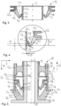
- a hydraulically damping bearing 10 in particular a hydraulically damping subframe bearing, which serves to support a subframe (not shown) of a motor vehicle.
- the bearing 10 is inserted into a receiving eye (not shown) of the subframe.
- the bearing 10 has a core 12 and an outer tube 14 that surrounds the core 12, forming a gap.
- the core 12 has a through-opening 13 through which a fastening element for fastening the bearing 10 to the vehicle body can be passed.
- the bearing 10 is inserted, in particular pressed, into a receiving eye of a subframe via the outer tube 14.
- the core 12 and the outer tube 14 can be made of metal or plastic.
- first elastomer body 15 is designed as an axial bearing 16
- second elastomer body 21 is designed as a radial bearing 18
- membrane 19 is designed as an intermediate membrane 20
- second elastomer body 21 is designed as a compensating membrane 22.
- the axial bearing 16 and the intermediate membrane 20 delimit a first fluid chamber 24, and the intermediate membrane 20 and the compensating membrane 22 delimit a second fluid chamber 26.
- Both fluid chambers 24, 26 are filled with a fluid and are fluidically connected to one another via a damping channel 28.
- the axial bearing 16 has a first elastomer body 15 which is approximately hollow conical and is integrally connected, in particular vulcanized, to the core 12 and the outer tube 14.
- the first elastomer body 15 is connected to the outer tube 14 in such a way that it protrudes from the outer tube 14 in the axial direction A.
- the first elastomer body 15 is arranged essentially outside a receiving eye in the inserted state.
- the outer tube 14 has a collar section 32 to which the first elastomer body 15 is vulcanized.
- the first elastomer body 15 is vulcanized to an inner surface of the outer tube 14.
- the core 12 has a stop plate 34 projecting vertically from the core 12 at the end.
- the stop plate 34 can be formed from the same material as the core 12, as in Fig.1 shown, or a separate part that can be positively, non-positively and/or materially connected to the core 12, as in Fig.2
- the first elastomer body 15 is vulcanized onto an outside of the core 12.
- the first elastomer body 15 can be connected to the stop plate 34 in a material-locking manner by means of vulcanization or a post-bonding process.
- the first elastomer body 15 can rest completely or partially against the stop plate 34 without adhesion or can not touch it in the KO position.
- the first elastomer body 15 has first stops 36, which are spaced from the stop plate to limit relative movement of core 12 and outer tube 14.
- the second elastomer body 21 designed as a radial bearing 18 has an inner sleeve 40a and an outer sleeve 42a.
- the second elastomer body 21 extends in the radial direction R and is integrally connected, in particular vulcanized, to the inner sleeve 40a and the outer sleeve 42a.
- the radial bearing 18 is attached to the core 12 and the outer tube 14 via the sleeves 40a, 42a by pushing the inner sleeve 40a onto the core 12, in particular pressing it on, and inserting the outer sleeve 42a into the opening of the outer tube 14, in particular pressing it in.
- the inner sleeve 40a can have a diameter that is smaller than the outer diameter of the core 12 and the outer sleeve 42a can have an outer diameter that is larger than the inner diameter of the outer tube 14.
- the radial bearing 18 has second stops 44 which are spaced apart from the core 12 or the inner sleeve 40a.
- the second stops 44 are formed from the same material as the second elastomer body 21.
- the radial bearing 18 is followed by the compensating membrane 22, which has an inner sleeve 40b and an outer sleeve 42b for fastening to the core 12 or in the outer tube 14.
- the compensating membrane 22 has an inner sleeve 40b and an outer sleeve 42b for fastening to the core 12 or in the outer tube 14.
- sealing elements are to be provided, for example, on the inner sleeve 40b and outer sleeve 42b.
- the inner sleeve 40b is pushed onto the core 12, in particular pressed on, and the outer sleeve 42b is inserted into the opening of the outer tube 14, in particular pressed in.
- the inner sleeve 40b can have a diameter that is smaller than the outer diameter of the core 12 and the outer sleeve 42b can have an outer diameter that is larger than the inner diameter of the outer tube 14.
- the compensating membrane 22 is made of an elastomeric material.
- the intermediate membrane 20 is arranged between the compensating membrane 22 and the axial bearing 16 and has an inner sleeve 40c and an outer sleeve 42c for fastening to the core 12 or in the outer tube 14.
- the inner sleeve 40b is pushed onto the core 12, in particular pressed on. and the outer sleeve 42b is inserted, in particular pressed, into the opening of the outer tube 14.
- the inner sleeve 40b can have a diameter that is smaller than the outer diameter of the core 12 and the outer sleeve 42b can have an outer diameter that is larger than the inner diameter of the outer tube 14.
- the damping channel 28 is introduced into the outer sleeve 42c.
- the intermediate membrane 20 is made of an elastomeric material.
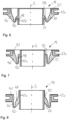
- the intermediate membrane 20 is largely rotationally symmetrical about an axis of symmetry S, wherein the intermediate membrane 20 has a first leg 46, a second leg 48 and a base 50 connecting the two legs to one another.
- the base 50 is approximately U-shaped.
- the first leg 46 is arranged radially on the outside, wherein an average thickness of the first leg 46 is at least twice as thick as the average thickness of the second leg 48.
- the first leg 46 expands continuously starting from the base 50, in particular the first leg 46 increases in a funnel shape.
- the first leg 46 has a connecting section 51 at the end, which is integrally connected to the outer sleeve 42c, in particular vulcanized thereto. As in Fig.3 As can be seen, the connecting section 51 encloses the outer sleeve 42c.
- the second leg 48 has a connecting section 51 at the end in the form of a thickening 52, which is materially connected, in particular vulcanized, to an outer side of the inner sleeve 42c.
- the intermediate membrane 20 can perform large movements in the axial direction A and/or in the radial direction R and at the same time is very rigid when there are differential pressures between the fluid chambers 24, 26; in particular, the base 50 can rest against the outer sleeve 40b when there are large movements in the axial direction A and a simultaneously occurring high differential pressure with high pressure in the first fluid chamber 24 and low pressure in the second fluid chamber 26.
- the intermediate membrane 20 has a high rigidity, which results in improved damping.
- Fig.4 the lengths of the legs 46, 48 and a distance A of the base 50 from the inner sleeve 42c are shown.
- the first leg 46 has a first length L1 and the second leg 48 has a second length L2, the first length L1 being greater than the second length L2.
- the first length L1 is three times as large as the second length L2. This is necessary because the longer leg is responsible for the high mobility in translational directions. At the same time, however, a greater length leads to low inflation stiffness and thus lower pumping performance. This is compensated for by the greater thickness of the longer leg. This creates a membrane geometry that is characterized by a long service life, but at the same time also allows a good pumping effect in the axial direction.
- each leg 46, 48 is defined by the distance in the Z direction between the lower reversal point U of the base 50 and the highest connection point P1, P2 of the respective leg 46, 48.
- the mathematical derivative of the function describing the upper surface is zero at the reversal point U of the base 50.
- the upper connection point of the radially outer leg is defined in such a way that beyond this point no significant strains occur in the elastomer of the connection area due to the movements of the membrane 19.
- the mutually facing surfaces of the inner sleeve 40c and the second leg 48 are spaced apart from each other, with a distance D of between approximately 1 mm and approximately 10 mm.
- the distance A is between approximately 2 mm and approximately 3 mm. This achieves a high pumping power and thus a high damping at large amplitudes.
- the base 50 of the membrane 19 can rest against a core or an inner tube at large amplitudes and thus become more rigid, which leads to high damping.
- the axial bearing 16 primarily absorbs the axial preloads acting on the bearing 10 in the Z direction.
- the Z loads during driving operation are also largely absorbed by the axial bearing 16, while the radial bearing 18 absorbs the majority of the radial loads occurring in the Y direction during operation and at the same time has a low axial rigidity or low radial rigidity in the X direction due to the distance of the second stops 44 from the core 12.
- the axial bearing 16 protrudes from the outer tube 14 in the axial direction A in such a way that the axial bearing 14 is arranged essentially outside the receiving eye when inserted.
- the axial bearing 16 Since the axial bearing 16 is arranged outside the receiving eye, it is not limited radially by the receiving eye, but only geometrically by the available installation space outside the receiving eye, so that the axial bearing 16 has a large outer diameter and thus a large expansion length. Due to the previously described different stiffness contributions in the Y and Z directions of the axial bearing 16 and radial bearing 18 and the arrangement of the axial bearing 16 outside the receiving eye, the axially damping bearing 10 can absorb high static loads or axial preloads and can be designed to last for a long time. In addition, the basic stiffness and the dynamic properties of the bearing 10 can be easily coordinated.
- the compensating membrane 22 and the intermediate membrane 20 can be installed preloaded during assembly so that they are in the KO position as shown in the Figures 1, 2 and 4 shown, have a reduced or even no axial deflection due to the static load or axial preload acting on the axial bearing 16 in the Z direction.
- the length of the first leg 46 is at least twice as long as that of the second leg 48. This allows the membrane 19 to perform large movements in the axial direction A and/or in the radial direction R.
- the average thickness of the first leg 46 is at least twice as large as that of the second leg 48. This makes the membrane 19 insensitive to swelling due to high differential pressures between the two fluid chambers 22, 24 filled with fluid. In most operating conditions, this leads to a high inflation stiffness of the membrane 19, which results in a large pump volume and thus in an improved damping effect.
- this design ensures that the membrane 19 is very stiff when there are differential pressures between the fluid chambers 22, 24.
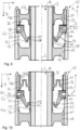
- a second embodiment of the hydraulic bearing 10 is shown, which differs from the first embodiment in the fastening of the first elastomer body 15 to the outer tube 14.
- the first elastomer body 15 is vulcanized to a ring 54 with a collar 56, by means of which the first elastomer body 15 is connected to the outer tube 14.
- the ring 54 is inserted into the outer tube 14, whereby the ring can be connected to the outer tube 14 in a form-fitting, force-fitting and/or material-fitting manner.
- the ring 54 is made from a plastic in the same way as the outer tube 15, it is connected to the outer tube 14 in a material-fitting and at the same time sealing manner, for example by means of laser transmission welding.
- ring 54 and/or the outer tube 15 are made from a metal, both are connected to one another in a form-fitting and/or force-fitting manner, for example by flanging or rolling the collar 56.
- a rubber seal (not shown) can be inserted between the ring 54 and the outer tube 14 to seal the second fluid chamber 26.
- a second embodiment of the membrane 19 designed as an intermediate membrane 20 is shown, which differs from the first embodiment in that that the first leg 46 is vulcanized to a projection 58 protruding from the inner sleeve 40b.
- a third embodiment of the membrane 19 designed as an intermediate membrane 20 is shown, which differs from the first embodiment in that the second leg 48 is longer.
- the length L2 of the second leg 48 corresponds to the length L1 of the first leg 46. This reduces the expansions in the intermediate membrane 20 that occur during movements in the axial direction A and/or in the radial direction, so that the intermediate membrane 20 has a long service life and is also dynamically soft.
- a fourth embodiment of the membrane 19 is shown, which differs from the other embodiments in that the radially inner second leg 48 is at least twice as thick as the radially outer first leg 48.
- a third embodiment of the hydraulically damping bearing 10 is shown, which differs from the first two embodiments in that no radial bearing 18 is present and the second elastomer body 21 is thicker compared to the previous embodiments.
- a fourth embodiment of the hydraulically damping bearing 10 is shown, which differs from the third embodiment in that the second elastomer body 21 is thin-walled and has the shape of a bellows 60. Since the second elastomer body 21 has the shape of a thin-walled bellows 60, the second fluid chamber 26 is a low-pressure compensation chamber.
- the membrane 19 is characterized in that the average thickness of one leg is at least twice as large as the other leg.
- the membrane 19 can perform large movements in the axial direction A and/or in the radial directions R and is insensitive to swelling due to high differential pressures between the two fluid chambers 24, 26 filled with fluid. This leads to a high inflation stiffness in most operating conditions. of the membrane 19, which results in a large pump volume and thus in an improved damping effect.
- this design ensures that the membrane 19 is very stiff at differential pressures between the fluid chambers 24, 26.
Landscapes
- Engineering & Computer Science (AREA)
- General Engineering & Computer Science (AREA)
- Mechanical Engineering (AREA)
- Combined Devices Of Dampers And Springs (AREA)
Claims (12)
- Membrane (19) pour un palier à amortissement hydraulique (10), qui présente une première branche (46), une deuxième branche (48) et une base (50) reliant les deux branches (46, 48) entre elles, caractérisée en ce que la base (50) est réalisée en forme de U avec une épaisseur uniforme et les branches (46, 48) font saillie de la base en forme de U (50), une épaisseur moyenne de l'une des branches (46, 48) étant au moins deux fois plus épaisse que celle de l'autre branche (46, 48), la section transversale de la branche (46, 48) en moyenne au moins deux fois plus épaisse s'élargit en continu à partir de la base (50), la branche (46, 48) en moyenne au moins deux fois plus épaisse présentant une première longueur (L1) et l'autre branche (46, 48) une deuxième longueur (L2), la première longueur (L1) étant au moins deux fois plus grande que la deuxième longueur (L2), la branche (46, 48) en moyenne au moins deux fois plus épaisse formant la branche située radialement à l'extérieur.
- Membrane selon l'une des revendications précédentes, caractérisée en ce que les branches (46, 48) présentent à leurs extrémités une section de liaison (51) qui peut être reliée par une liaison par la forme, par une liaison par la force et/ou par une liaison par le matièrau à un noyau (12) et/ou à un tube extérieur (14) d'une couche d'amortissement hydraulique (10).
- Membrane selon l'une des revendications précédentes, caractérisée en ce que les surfaces tournées l'une vers l'autre de la section de liaison (51) et/ou d'un manchon intérieur (40c) et de la branche radialement intérieure (48) sont espacées l'une de l'autre, une distance (D) étant comprise entre environ 1 mm et environ 10 mm.
- Membrane selon la revendication 2 ou 3, caractérisée en ce que les sections de liaison (51) sont reliées à une douille intérieure (40c) et/ou à une douille extérieure (42c), la douille intérieure (40c) pouvant être enfilée sur le noyau (12) et la douille extérieure (42c) pouvant être insérée dans le tube extérieur (14), un canal d'amortissement (28) étant de préférence ménagé dans la douille extérieure (42c) de la membrane (19).
- Support à amortissement hydraulique (10) présentant un noyau (12) et un tube extérieur (14) entourant le noyau (12), un premier corps élastomère (15), une membrane (19) selon l'une des revendications 1 à 4 et un deuxième corps élastomère (21) étant disposés entre le noyau (12) et le tube extérieur (14), le premier corps élastomère (15) et la membrane (19) délimitant une première chambre à fluide (24) et la membrane (19) et le deuxième corps élastomère (21) délimitant une deuxième chambre à fluide (26), et les chambres à fluide (24, 26) étant remplies d'un fluide et reliées entre elles par un canal d'amortissement (28) de manière à conduire le fluide.
- Support à amortissement hydraulique selon la revendication 5, caractérisé en ce qu'un troisième corps élastomère (17) est disposé entre le noyau (12) et le tube extérieur (14), dans lequel, de préférence, le premier corps élastomère (15), le deuxième corps élastomère (21) et/ou le troisième corps élastomère (17) est relié au noyau (12) et/ou à la douille extérieure (42a, 42b, 42c) par une liaison par la forme, par une liaison par la force et/ou par une liaison par le matériau ; le deuxième corps élastomère (21) et/ou le troisième corps élastomère (17) présentant de préférence une douille intérieure (40a, 40b) et/ou une douille extérieure (42a, 42b), la douille intérieure (40a, 40b) pouvant être enfilée sur le noyau (12) et la douille extérieure (42a, 42b) pouvant être insérée dans le tube extérieur (14).
- Support à amortissement hydraulique selon la revendication 5 ou 6, caractérisé en ce que le premier corps élastomère (15) est un palier axial (16).
- Support à amortissement hydraulique selon la revendication 6 ou 7, caractérisé en ce que le troisième corps élastomère (17) est un support radial (18).
- Support à amortissement hydraulique selon l'une des revendications 5 à 8, caractérisé en ce que le deuxième corps élastomère (21) est une membrane d'équilibrage (22).
- Support à amortissement hydraulique (10) selon l'une des revendications 8 ou 9, caractérisé en ce que le palier radial (18) présente une rigidité dans la direction Y qui est supérieure d'au moins un facteur 10 à sa rigidité dans la direction Z.
- Support à amortissement hydraulique (10) selon l'une des revendications 8 à 10, caractérisé en ce que le palier axial (16) présente une rigidité dans la direction Z qui est supérieure d'au moins un facteur 2 à la rigidité du palier radial (18) dans la direction Z.
- Support à amortissement hydraulique (10) selon l'une des revendications 5 à 11, caractérisé en ce que le premier corps en élastomère (15), le deuxième corps en élastomère (21) et/ou le troisième corps en élastomère (17) est relié au noyau (12) et/ou à la douille extérieure (42a, 42b, 42c) par une liaison par la forme, par une liaison par la force et/ou par une liaison par le matériau.
Applications Claiming Priority (1)
| Application Number | Priority Date | Filing Date | Title |
|---|---|---|---|
| PCT/EP2018/056120 WO2019174715A1 (fr) | 2018-03-12 | 2018-03-12 | Membrane et palier à amortissement hydraulique |
Publications (2)
| Publication Number | Publication Date |
|---|---|
| EP3589861A1 EP3589861A1 (fr) | 2020-01-08 |
| EP3589861B1 true EP3589861B1 (fr) | 2024-05-01 |
Family
ID=61750090
Family Applications (1)
| Application Number | Title | Priority Date | Filing Date |
|---|---|---|---|
| EP18712534.9A Active EP3589861B1 (fr) | 2018-03-12 | 2018-03-12 | Membrane et palier à amortissement hydraulique |
Country Status (4)
| Country | Link |
|---|---|
| US (1) | US11448285B2 (fr) |
| EP (1) | EP3589861B1 (fr) |
| CN (1) | CN110709623B (fr) |
| WO (1) | WO2019174715A1 (fr) |
Families Citing this family (2)
| Publication number | Priority date | Publication date | Assignee | Title |
|---|---|---|---|---|
| DE102020113527A1 (de) | 2020-05-19 | 2021-11-25 | Vibracoustic Se | Axialdämpfendes, hydraulisches Elastomerlager |
| CN114475200A (zh) * | 2020-10-23 | 2022-05-13 | 现代自动车株式会社 | 用于制造车辆的模块化安装结构和组合方法 |
Citations (1)
| Publication number | Priority date | Publication date | Assignee | Title |
|---|---|---|---|---|
| US20130187318A1 (en) * | 2010-09-22 | 2013-07-25 | Bridgestone Corporation | Anti-vibration device |
Family Cites Families (27)
| Publication number | Priority date | Publication date | Assignee | Title |
|---|---|---|---|---|
| IT1159378B (it) * | 1983-03-15 | 1987-02-25 | Siette Spa | Sopporto elastico ammortizzante particolarmente per motori di autoveicoli cabine di autocarri e simili applicazioni |
| JPH0650135B2 (ja) | 1988-07-28 | 1994-06-29 | 東洋ゴム工業株式会社 | 液体封入式ボディマウント |
| JPH0815041A (ja) | 1994-06-30 | 1996-01-19 | Toshiba Corp | 熱塊検出装置 |
| JPH08152041A (ja) * | 1994-11-28 | 1996-06-11 | Bridgestone Corp | 防振装置 |
| JPH08177945A (ja) * | 1994-12-21 | 1996-07-12 | Tokai Rubber Ind Ltd | 流体封入式筒型防振装置 |
| JP3477920B2 (ja) * | 1995-06-23 | 2003-12-10 | 東海ゴム工業株式会社 | 流体封入式防振支持体 |
| DE19833537A1 (de) | 1998-07-25 | 2000-02-03 | Lemfoerder Metallwaren Ag | Fahrwerkslager |
| DE60021052T2 (de) * | 1999-12-28 | 2005-12-22 | Yamashita Rubber K.K. | Flüssigkeitsenthaltende und Schwingungsdämpfende Vorrichtung |
| DE10037954B4 (de) * | 2000-05-30 | 2012-01-19 | Carl Freudenberg Kg | Hydrolager |
| EP1249634B1 (fr) * | 2001-04-10 | 2008-01-02 | Yamashita Rubber Kabushiki Kaisha | Dispositif anti-vibratoire renfermant du liquide |
| US7007934B2 (en) * | 2001-07-02 | 2006-03-07 | Tokai Rubber Industries, Ltd. | Fluid-filled vibration damping device |
| JP4110567B2 (ja) * | 2002-07-04 | 2008-07-02 | 東海ゴム工業株式会社 | 流体封入式筒形防振装置 |
| JP4003131B2 (ja) * | 2003-01-31 | 2007-11-07 | 東海ゴム工業株式会社 | 流体封入式防振装置 |
| JP4055591B2 (ja) * | 2003-01-31 | 2008-03-05 | 東海ゴム工業株式会社 | 流体封入式防振装置 |
| JP4022767B2 (ja) * | 2003-10-31 | 2007-12-19 | 東海ゴム工業株式会社 | 流体封入式筒形マウント |
| JP4060309B2 (ja) * | 2004-11-04 | 2008-03-12 | 本田技研工業株式会社 | 車両用防振装置 |
| JP4277316B2 (ja) * | 2005-03-30 | 2009-06-10 | 東海ゴム工業株式会社 | 防振装置 |
| KR100809035B1 (ko) * | 2006-05-17 | 2008-03-04 | (주)디티알 | 부시형 유체봉입식 고무 마운트 및 그 제조방법 |
| DE102007016399B4 (de) * | 2007-04-03 | 2009-12-31 | Zf Friedrichshafen Ag | Biaxial dämpfendes Hydrolager |
| CN101932849B (zh) * | 2008-08-01 | 2013-02-06 | 东海橡塑工业株式会社 | 流体封入式隔振装置 |
| CN102884338B (zh) | 2010-03-08 | 2015-01-21 | 株式会社普利司通 | 液体封入式防振装置及其制造方法 |
| US9200694B2 (en) * | 2010-09-27 | 2015-12-01 | Bridgestone Corporation | Vibration damping device |
| DE102011109128A1 (de) * | 2011-08-02 | 2013-02-07 | Carl Freudenberg Kg | Hydraulisch dämpfendes Lager und Kraftfahrzeug damit |
| CA2820000C (fr) * | 2012-09-05 | 2019-12-24 | Jeffery Michael Bradshaw | Dispositif d'installation hydraulique a volet axial |
| US10215252B2 (en) * | 2016-09-06 | 2019-02-26 | Vibracoustic North America L.P. | Hydraulic body mount |
| JP6877227B2 (ja) * | 2017-04-17 | 2021-05-26 | 株式会社ブリヂストン | 防振装置 |
| DE102019109608B4 (de) * | 2019-04-11 | 2021-06-24 | Vibracoustic Ag | Elastisches Lager |
-
2018
- 2018-03-12 CN CN201880034833.6A patent/CN110709623B/zh active Active
- 2018-03-12 EP EP18712534.9A patent/EP3589861B1/fr active Active
- 2018-03-12 US US16/617,688 patent/US11448285B2/en active Active
- 2018-03-12 WO PCT/EP2018/056120 patent/WO2019174715A1/fr unknown
Patent Citations (1)
| Publication number | Priority date | Publication date | Assignee | Title |
|---|---|---|---|---|
| US20130187318A1 (en) * | 2010-09-22 | 2013-07-25 | Bridgestone Corporation | Anti-vibration device |
Also Published As
| Publication number | Publication date |
|---|---|
| CN110709623B (zh) | 2022-02-25 |
| US20200182327A1 (en) | 2020-06-11 |
| CN110709623A (zh) | 2020-01-17 |
| EP3589861A1 (fr) | 2020-01-08 |
| US11448285B2 (en) | 2022-09-20 |
| WO2019174715A1 (fr) | 2019-09-19 |
Similar Documents
| Publication | Publication Date | Title |
|---|---|---|
| EP0617211B1 (fr) | Manchon élastique à amortissement hydraulique | |
| EP2304268B1 (fr) | Palier à douille à amortissement hydraulique | |
| DE19624886C2 (de) | Flüssigkeitsdämpfungsvorrichtung mit unterschiedlich großen Federsteifigkeitswerten in zwei zueinander senkrechten Richtungen | |
| EP2142821B1 (fr) | Douille élastomère à amortissement hydraulique | |
| EP3744996B1 (fr) | Palier élastique | |
| EP2188548B1 (fr) | Palier à douille élastomère et amortissement hydraulique | |
| EP1686282A1 (fr) | Manchon à rigidité radiale variable en direction circonférentielle | |
| EP3589861B1 (fr) | Membrane et palier à amortissement hydraulique | |
| EP3737875B1 (fr) | Coussinet de palier hydraulique | |
| EP1707842A1 (fr) | Manchon à amortissement hydraulique avec étanchéité axiale | |
| DE4015213C2 (de) | Schwingungsdämpfungsvorrichtung | |
| EP3440379B1 (fr) | Palier hydraulique | |
| DE102013105326B4 (de) | Hydraulische Buchse | |
| EP1908987A2 (fr) | Coussinet élastique avec amortissement hydraulique | |
| EP3488122B1 (fr) | Palier à amortissement hydraulique | |
| EP3218620B1 (fr) | Manchon hydraulique ainsi que véhicule présentant un tel manchon hydraulique | |
| DE102020113527A1 (de) | Axialdämpfendes, hydraulisches Elastomerlager | |
| EP2604884B1 (fr) | Support hydraulique et son utilisation | |
| DE102013020682B4 (de) | Hydraulisch dämpfendes Lager für ein Kraftfahrzeug und Verfahren zum radialen Vorspannen des Elastomerkörpers eines Lagers | |
| EP2058550B1 (fr) | Coussinet élastique avec amortissement hydraulique | |
| DE102004014328A1 (de) | Hydraulisch dämpfendes Gummilager | |
| DE102011001629A1 (de) | Hydrobuchse | |
| EP2023005A2 (fr) | Support élastique | |
| DE102022115056A1 (de) | Hydraulisch dämpfendes Lager | |
| DE102019007526A1 (de) | Hydraulisch dämpfendes Buchsenlager |
Legal Events
| Date | Code | Title | Description |
|---|---|---|---|
| STAA | Information on the status of an ep patent application or granted ep patent |
Free format text: STATUS: UNKNOWN |
|
| STAA | Information on the status of an ep patent application or granted ep patent |
Free format text: STATUS: THE INTERNATIONAL PUBLICATION HAS BEEN MADE |
|
| PUAI | Public reference made under article 153(3) epc to a published international application that has entered the european phase |
Free format text: ORIGINAL CODE: 0009012 |
|
| STAA | Information on the status of an ep patent application or granted ep patent |
Free format text: STATUS: REQUEST FOR EXAMINATION WAS MADE |
|
| 17P | Request for examination filed |
Effective date: 20191004 |
|
| AK | Designated contracting states |
Kind code of ref document: A1 Designated state(s): AL AT BE BG CH CY CZ DE DK EE ES FI FR GB GR HR HU IE IS IT LI LT LU LV MC MK MT NL NO PL PT RO RS SE SI SK SM TR |
|
| AX | Request for extension of the european patent |
Extension state: BA ME |
|
| DAV | Request for validation of the european patent (deleted) | ||
| DAX | Request for extension of the european patent (deleted) | ||
| RAP3 | Party data changed (applicant data changed or rights of an application transferred) |
Owner name: VIBRACOUSTIC SE |
|
| STAA | Information on the status of an ep patent application or granted ep patent |
Free format text: STATUS: EXAMINATION IS IN PROGRESS |
|
| 17Q | First examination report despatched |
Effective date: 20220525 |
|
| GRAP | Despatch of communication of intention to grant a patent |
Free format text: ORIGINAL CODE: EPIDOSNIGR1 |
|
| STAA | Information on the status of an ep patent application or granted ep patent |
Free format text: STATUS: GRANT OF PATENT IS INTENDED |
|
| INTG | Intention to grant announced |
Effective date: 20240108 |
|
| GRAS | Grant fee paid |
Free format text: ORIGINAL CODE: EPIDOSNIGR3 |
|
| GRAA | (expected) grant |
Free format text: ORIGINAL CODE: 0009210 |
|
| STAA | Information on the status of an ep patent application or granted ep patent |
Free format text: STATUS: THE PATENT HAS BEEN GRANTED |
|
| REG | Reference to a national code |
Ref country code: DE Ref legal event code: R081 Ref document number: 502018014531 Country of ref document: DE Owner name: VIBRACOUSTIC SE, DE Free format text: FORMER OWNER: ANMELDERANGABEN UNKLAR / UNVOLLSTAENDIG, 80297 MUENCHEN, DE |
|
| AK | Designated contracting states |
Kind code of ref document: B1 Designated state(s): AL AT BE BG CH CY CZ DE DK EE ES FI FR GB GR HR HU IE IS IT LI LT LU LV MC MK MT NL NO PL PT RO RS SE SI SK SM TR |
|
| RAP3 | Party data changed (applicant data changed or rights of an application transferred) |
Owner name: VIBRACOUSTIC SE |
|
| REG | Reference to a national code |
Ref country code: GB Ref legal event code: FG4D Free format text: NOT ENGLISH |
|
| REG | Reference to a national code |
Ref country code: CH Ref legal event code: EP |
|
| REG | Reference to a national code |
Ref country code: DE Ref legal event code: R096 Ref document number: 502018014531 Country of ref document: DE |
|
| REG | Reference to a national code |
Ref country code: IE Ref legal event code: FG4D Free format text: LANGUAGE OF EP DOCUMENT: GERMAN |