EP1908987A2 - Coussinet élastique avec amortissement hydraulique - Google Patents
Coussinet élastique avec amortissement hydraulique Download PDFInfo
- Publication number
- EP1908987A2 EP1908987A2 EP07019119A EP07019119A EP1908987A2 EP 1908987 A2 EP1908987 A2 EP 1908987A2 EP 07019119 A EP07019119 A EP 07019119A EP 07019119 A EP07019119 A EP 07019119A EP 1908987 A2 EP1908987 A2 EP 1908987A2
- Authority
- EP
- European Patent Office
- Prior art keywords
- outer sleeve
- window
- radially
- chamber
- channel
- Prior art date
- Legal status (The legal status is an assumption and is not a legal conclusion. Google has not performed a legal analysis and makes no representation as to the accuracy of the status listed.)
- Withdrawn
Links
Images


Classifications
-
- F—MECHANICAL ENGINEERING; LIGHTING; HEATING; WEAPONS; BLASTING
- F16—ENGINEERING ELEMENTS AND UNITS; GENERAL MEASURES FOR PRODUCING AND MAINTAINING EFFECTIVE FUNCTIONING OF MACHINES OR INSTALLATIONS; THERMAL INSULATION IN GENERAL
- F16F—SPRINGS; SHOCK-ABSORBERS; MEANS FOR DAMPING VIBRATION
- F16F13/00—Units comprising springs of the non-fluid type as well as vibration-dampers, shock-absorbers, or fluid springs
- F16F13/04—Units comprising springs of the non-fluid type as well as vibration-dampers, shock-absorbers, or fluid springs comprising both a plastics spring and a damper, e.g. a friction damper
- F16F13/06—Units comprising springs of the non-fluid type as well as vibration-dampers, shock-absorbers, or fluid springs comprising both a plastics spring and a damper, e.g. a friction damper the damper being a fluid damper, e.g. the plastics spring not forming a part of the wall of the fluid chamber of the damper
- F16F13/08—Units comprising springs of the non-fluid type as well as vibration-dampers, shock-absorbers, or fluid springs comprising both a plastics spring and a damper, e.g. a friction damper the damper being a fluid damper, e.g. the plastics spring not forming a part of the wall of the fluid chamber of the damper the plastics spring forming at least a part of the wall of the fluid chamber of the damper
- F16F13/14—Units of the bushing type, i.e. loaded predominantly radially
Definitions
- the invention relates to an elastic bushing with hydraulic damping, in particular for bearings in a motor vehicle or as a machine bearing according to the preamble of claim 1.
- a known, generic elastic bushing with hydraulic damping ( DE 36 17 787 C2 ) consists of an inner part for connection to a first component to be supported and an outer tube and of an elastomeric body between the inner part and the outer tube.
- bearing bushes on two radially opposite, filled with hydraulic fluid working chambers, which are formed by associated recesses in the outer tube and in the elastomer body and by a liquid-tight final outer sleeve.
- the two working chambers are interconnected by a flow channel.
- the elastomer body undergoes a static and dynamic deformation in conjunction with an alternating compressive and tensile stress. Since the elastomeric body is preferably firmly connected by vulcanization with the inner part and the outer tube, tensile loads can impair the bearing function and lead to damage to the failure of the bearing. It is already well known to provide an elastomeric body in a bearing with a bias to compensate for such tensile stresses:
- an elastic bushing with hydraulic damping is known ( DE 103 51 229 A1 ), in which the outer tube of individual sections, namely two respective end face support ring parts and a separate central part is formed, which is braced radially inwardly during application of the outer sleeve.
- the end-side support ring parts are each decoupled by a gap to separate middle part and are not deformed in the desired manner uncontrolled, so that the local sealing surfaces and sealing lips are not adversely affected to the outer sleeve out.
- this division of the outer tube into a plurality of separate tube parts leads to an increased effort in the vulcanization, since these separate parts must be individually introduced into the vulcanizing mold and kept there in the correct position.
- the object of the invention is to develop a generic elastic bushing with hydraulic damping so that it is inexpensive to produce with a simple structure and good function with a bias in the elastomer body.
- an elastomer layer is applied to the outer tube at least in some areas radially outside and formed in one or both axially lateral areas at least one flow channel with its channel bottom and the channel side walls, wherein the flow channel is bounded radially outside of the outer sleeve liquid-tight.
- the outer tube is formed as a one-piece cage part, each with a frontally circumferentially closed and sealing lips with the outer sleeve supporting the support ring part and with two radially opposite the support ring parts axially connecting tube web parts.
- Recesses are formed for the working chambers between the pipe web parts, wherein the pipe web parts are assigned to the elastomer body, which has no recesses in these areas.
- At least one window is mounted in the pipe web parts, which is associated with at least one pressure element, which is arranged in the window region and projects radially further than the inner diameter of the outer sleeve prior to assembly of the outer sleeve.
- the at least one pressure element is then displaced radially inward by applying a bias in the elastomer body, said displacement is largely decoupled from the support ring parts and / or pipe web parts, so that they are advantageously not unduly mitverformt.
- the outer tube as a one-piece cage part can be easily introduced and held in a vulcanizing mold in the production, so that a cost-effective production is possible.
- a pressure element consists only of a radial, passing through the window bulge of elastomeric material of the elastomeric body, which is displaced radially radially inwardly through the window upon attachment of the outer sleeve by applying a bias.
- a pressure element is formed as in the window area in the elastomeric material molded or inserted pressure piece.
- a pressure piece can be made of relatively stable material, for. B. made of metal or hard plastic and have a curved outer surface. When attaching the outer sleeve, the pressure piece is then displaced through the window radially inward by applying a bias in the radially underlying elastomer body region.
- a pressure element in the manner of a window cover is formed using the tube web window portion, which is preferably molded in the elastomer region and before attaching the outer sleeve by a radially outwardly facing bend and / or applied elastomeric material with respect to the Inner diameter of the outer sleeve has radial bulge. When attaching the outer sleeve then this radial bulge is displaced radially inward in conjunction with a displacement of the window cover and under application of the desired bias.
- the tube web window portion as a window cover at least one side, preferably on both sides opposite one another Film hinge connected to the adjacent window portion, wherein preferably the film hinge is formed according to claim 6 in the form of one or more beads.
- the radially displaceable window cover hangs integrally with the rest of the outer tube, so that this can be advantageously inserted as a one-piece cage part in a Vulkanisierform.
- the flow channel consists of two sub-channels, each of which a sub-channel laterally adjacent to the working chambers in a transverse plane, wherein the first sub-channel with the first working chamber via a first lateral Chamber outlet opening is connected, in addition to the first working chamber and the second working chamber passes in the circumferential direction and opens into a transition contour chamber.
- the second subchannel is correspondingly connected to the second working chamber via a second lateral chamber outlet opening, runs past the second working chamber and the first working chamber in the opposite circumferential direction and also opens into the transitional contour chamber, through which in the longitudinal direction of a flow connection between the first sub-channel and the second Partial channel is made.
- the transition contour chamber is advantageously designed as a cylindrical section and has a larger cross section than the subchannels.
- flow guide contours between the opening sub-channels are provided in the transition contour chamber.
- the bearing bush is in a receiving eye of the second component to be stored, for example, a cab of a truck, pressed with about horizontal bushing axis and vertically superimposed working chambers. A built-in bushing is then suitable for a damped elastic support vertical loads.
- the inner part with elastomeric material coated stops are formed, which protrude radially into the working chambers, taking into account a free spring travel. In strong rebound or rebound these attacks on the inside of the outer sleeve to the plant and are based on it in the receiving eye.
- the inner part is tapered conically downwards in cross section, wherein the inner part is made of plastic with a central bore for receiving a pivot axis.
- a bearing is well suited for supporting the cab of a truck.
- an elastic bushing 1 is shown in each case, which consists of an inner part 2, an outer tube 3 and an elastomeric body 4 between the inner part 2 and the outer tube 3.
- FIGS. 1 and 2 two radially opposite, filled with hydraulic fluid working chambers are formed (upper working chamber 5 and lower working chamber 6), which are made by associated recesses in the outer tube 3 and in the elastomer body 4 and by a liquid-tight final outer sleeve 7.
- the working chambers 5, 6 are limited with respect to the elastomeric material at the respective chamber bottoms of the two-sided strongly dimensioned elastomer blocks 24a, 24b and in the side regions of the thin-walled elastomeric walls 8 retracted to the center of the bearing.
- Due to the recesses on the outer tube 3 in the region of the working chambers 5, 6 are in Fig. 1, only the opposite tube web parts 23a, 23b of the outer tube 3 and correspond in Fig. 2, only the molded circumferential support ring parts 22a, 22b of the outer tube 3, the closer in conjunction with FIG. 4 will be described.
- an elastomer layer 9 is radially outwardly applied, in which a flow channel 10 are formed with its two sub-channels 10a, 10b and a transition contour chamber 11, wherein the sub-channels 10a, 10b and the transition contour chamber 11 are bounded radially outside of the outer sleeve 7 liquid-tight ,
- the inner part 2 On the inner part 2, opposing, coated with elastomeric material 13 stops 14 are integrally formed in an axially central region, each projecting radially into the working chambers 5, 6.
- the inner part 2 is tapered conically downwards in cross section. It is made of plastic with a central bore 15 for receiving a metallic pivot axis.
- Fig. 3 is a perspective view of the elastic bushing 1, but without the outer sleeve 7 is shown. There are clearly the inner part 2, the upper working chamber 5 with the upper stop 14, as well as the frontally encircling annular regions 16 and 17 with the formed elastomeric sealing lips for the outer sleeve 7 recognizable.
- the elastomer layer 9 can be seen, in which the sub-channels 10a, 10b and the transition contour chamber 11 are formed.
- the sub-channels 10a and 10b each extend laterally adjacent to the working chambers 5 and 6.
- the sub-channel 10b is connected to the upper working chamber 5 via a lateral chamber outlet opening 18b. From there, the sub-channel 10b runs past the upper working chamber 5 and the lower working chamber 6 in the circumferential direction and opens at the junction 19b into the transition contour chamber 11.
- the other subchannel 10a begins at a chamber outlet opening 18a (not visible in FIG. 3) of the lower working chamber 6 and runs in the opposite circumferential direction as far as the junction 19a into the transitional chamber 11 next to the lower working chamber 6 and the upper working chamber 5 Transitional contour chamber 11, the flow connection between the sub-channels 10a, 10b and their junctions 19a, 19b made.
- the transitional contour chamber 11 is partially formed as a cylindrical portion having a vertically extending portion surface.
- the upper boundary 20 of the current-carrying contour has a flow-optimized curve between the junctions 19a and 19b, wherein additionally formed in the lower region of the transitional contour chamber 11 below and laterally to the junction 19a vertically aligned longitudinal slats 21, the upper connecting line of a lower boundary of the current flow contour approximately parallel with the running upper limit 20 corresponds.
- the outer tube 3 as a one-piece cage member, preferably made of metal, shown with frontally circumferentially closed support ring parts 22a, 22b and with two radially opposite the support ring portions 22a and 22b axially connecting tube web portions 23a, 23b.
- the support ring parts are radially outwardly coated in the finished bearing bush to form the end-side annular regions 16, 17 and the sealing lips with elastomeric material.
- the pipe web parts 23a, 23b are assigned to the two opposing elastomer blocks 24a, 24b of the elastomer body 4 and formed there. Between the pipe web parts, the recesses 25a, 25b for the working chambers 5, 6 recessed.
- window covers 27a, 27b are of the same material with the tube web parts 23a, 23b formed from the tube web window sections, which are exposed here each with cut away in the axial direction columns 28a, 28b and each axially opposite by hinged-acting beads 29a, 29b connected to the adjacent window area.
- the location of the column and cutouts could be reversed. Even a one-sided hinge connection would be possible with approximately the same function.
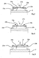
- FIG. 5 shows a longitudinal section of a first embodiment along the line CC from FIG. 1, so that here a top view of the cut, already prestressed elastomer blocks 24a, 24b with the outer sleeve 7 already plugged in and pressed on is shown.
- the radial bulge 30 is shown in broken lines for the first embodiment before attaching the outer sleeve 7, which may be formed by a corresponding radially outward bending of the window cover and / or by applied elastomer.
- this radial bulge 30 is displaced radially inward, as shown in Fig. 5, whereby a bias voltage is applied in the elastomeric blocks 24a, 24b.
- the radially displaced radially inwardly elastomeric material is indicated by the dashed lines 31 and the insertion of the outer sleeve radially inwardly acting force by the arrows F.
- the window cover 27a has a bending which remains also in the prestressed state to the outside.
- the beads 29a, 29b are formed as double beads.
- the window 26a is cut out as a whole and a pressure piece 31 formed in the elastomeric material is arranged in this area.
- the pressure piece 31 protrudes with a bulge radially beyond the inner diameter of the outer sleeve and is displaced when plugging the outer sleeve radially inward under application of a bias in the elastomer block 24a.
Landscapes
- Engineering & Computer Science (AREA)
- General Engineering & Computer Science (AREA)
- Mechanical Engineering (AREA)
- Combined Devices Of Dampers And Springs (AREA)
- Support Of The Bearing (AREA)
Applications Claiming Priority (1)
| Application Number | Priority Date | Filing Date | Title |
|---|---|---|---|
| DE200610047445 DE102006047445A1 (de) | 2006-10-07 | 2006-10-07 | Elastische Lagerbuchse mit hydraulischer Dämpfung |
Publications (2)
| Publication Number | Publication Date |
|---|---|
| EP1908987A2 true EP1908987A2 (fr) | 2008-04-09 |
| EP1908987A3 EP1908987A3 (fr) | 2010-07-07 |
Family
ID=38984234
Family Applications (1)
| Application Number | Title | Priority Date | Filing Date |
|---|---|---|---|
| EP07019119A Withdrawn EP1908987A3 (fr) | 2006-10-07 | 2007-09-28 | Coussinet élastique avec amortissement hydraulique |
Country Status (2)
| Country | Link |
|---|---|
| EP (1) | EP1908987A3 (fr) |
| DE (1) | DE102006047445A1 (fr) |
Cited By (3)
| Publication number | Priority date | Publication date | Assignee | Title |
|---|---|---|---|---|
| CN108343701A (zh) * | 2017-01-23 | 2018-07-31 | 株洲时代新材料科技股份有限公司 | 一种液压衬套 |
| WO2018171963A1 (fr) * | 2017-03-23 | 2018-09-27 | Vibracoustic Gmbh | Coussinet |
| CN114658792A (zh) * | 2020-12-22 | 2022-06-24 | 威巴克欧洲股份公司 | 具有支承部位的液压衬套和用于制造这种衬套的方法 |
Families Citing this family (1)
| Publication number | Priority date | Publication date | Assignee | Title |
|---|---|---|---|---|
| DE102007022410B4 (de) | 2007-05-10 | 2017-03-23 | Audi Ag | Hydraulisch dämpfende Elastomerbuchse |
Family Cites Families (4)
| Publication number | Priority date | Publication date | Assignee | Title |
|---|---|---|---|---|
| JPH0565933A (ja) * | 1991-09-06 | 1993-03-19 | Bridgestone Corp | 防振装置 |
| DE10146154B4 (de) * | 2001-09-19 | 2007-04-26 | Trelleborg Automotive Technical Centre Gmbh | Hydraulisch dämpfende Buchse |
| JP3895702B2 (ja) * | 2003-04-08 | 2007-03-22 | 本田技研工業株式会社 | 液体封入マウント装置 |
| ITTO20050147A1 (it) * | 2005-03-08 | 2006-09-09 | Gomma C F Spa | Supporto idroelastico, in particolare per il collegamento di un gruppo motopropulsore ad un veicolo. |
-
2006
- 2006-10-07 DE DE200610047445 patent/DE102006047445A1/de not_active Withdrawn
-
2007
- 2007-09-28 EP EP07019119A patent/EP1908987A3/fr not_active Withdrawn
Cited By (5)
| Publication number | Priority date | Publication date | Assignee | Title |
|---|---|---|---|---|
| CN108343701A (zh) * | 2017-01-23 | 2018-07-31 | 株洲时代新材料科技股份有限公司 | 一种液压衬套 |
| CN108343701B (zh) * | 2017-01-23 | 2020-07-14 | 株洲时代瑞唯减振装备有限公司 | 一种液压衬套 |
| WO2018171963A1 (fr) * | 2017-03-23 | 2018-09-27 | Vibracoustic Gmbh | Coussinet |
| WO2018172492A1 (fr) * | 2017-03-23 | 2018-09-27 | Vibracoustic Gmbh | Coussinet de palier |
| CN114658792A (zh) * | 2020-12-22 | 2022-06-24 | 威巴克欧洲股份公司 | 具有支承部位的液压衬套和用于制造这种衬套的方法 |
Also Published As
| Publication number | Publication date |
|---|---|
| DE102006047445A1 (de) | 2008-04-10 |
| EP1908987A3 (fr) | 2010-07-07 |
Similar Documents
| Publication | Publication Date | Title |
|---|---|---|
| DE19624886C2 (de) | Flüssigkeitsdämpfungsvorrichtung mit unterschiedlich großen Federsteifigkeitswerten in zwei zueinander senkrechten Richtungen | |
| DE102005043234B4 (de) | Verfahren zur Herstellung eines elastomeren Buchsenlagers | |
| EP0617211A1 (fr) | Manchon élastique à amortissement hydraulique | |
| EP1270987A2 (fr) | Support pour un agrégat en forme de manchon | |
| DE3882824T2 (de) | Elastische Buchse mit Fluiddämpfung. | |
| WO2018171963A1 (fr) | Coussinet | |
| WO2002084143A1 (fr) | Palier a coussinet-douille a amortissement hydraulique | |
| DE102014001943A1 (de) | Elastomer-Lagerbuchse, insbesondere zur Lagerung eines Stoßdämpfers einer Fahrzeug-Achsanbindung | |
| EP1908987A2 (fr) | Coussinet élastique avec amortissement hydraulique | |
| EP3589861B1 (fr) | Membrane et palier à amortissement hydraulique | |
| DE102004031559A1 (de) | Elastomeres Buchsenlager mit verbessertem Torsionsverhalten | |
| EP2657566B1 (fr) | Support hydraulique doté d'une lèvre d'étanchéité fabriquée sous forme de composant séparé | |
| EP1908988B1 (fr) | Tube extérieur pour un coussinet élastique à amortissement hydraulique | |
| DE102004014328B4 (de) | Hydraulisch dämpfendes Gummilager | |
| EP2076688B1 (fr) | Procédé de calibrage d'un ressort en élastomère d'un palier | |
| DE102021108720B4 (de) | Selbsthemmendes Buchsenlager | |
| DE102005054852A1 (de) | Hydrolager und Verfahren zur Herstellung eines Hydrolagers | |
| DE3441806C2 (fr) | ||
| DE102007026469B4 (de) | Modulares Elastomerlager | |
| EP2058550B1 (fr) | Coussinet élastique avec amortissement hydraulique | |
| EP1651884B1 (fr) | Douille-palier d'amortissement hydraulique | |
| EP1923593B1 (fr) | Coussinet radial | |
| EP2023005A2 (fr) | Support élastique | |
| EP1908986B1 (fr) | Coussinet élastique avec amortissement hydraulique | |
| DE102005054851A1 (de) | Hydrolager und Verfahren zur Herstellung eines Hydrolagers |
Legal Events
| Date | Code | Title | Description |
|---|---|---|---|
| PUAI | Public reference made under article 153(3) epc to a published international application that has entered the european phase |
Free format text: ORIGINAL CODE: 0009012 |
|
| AK | Designated contracting states |
Kind code of ref document: A2 Designated state(s): AT BE BG CH CY CZ DE DK EE ES FI FR GB GR HU IE IS IT LI LT LU LV MC MT NL PL PT RO SE SI SK TR |
|
| AX | Request for extension of the european patent |
Extension state: AL BA HR MK RS |
|
| PUAL | Search report despatched |
Free format text: ORIGINAL CODE: 0009013 |
|
| AK | Designated contracting states |
Kind code of ref document: A3 Designated state(s): AT BE BG CH CY CZ DE DK EE ES FI FR GB GR HU IE IS IT LI LT LU LV MC MT NL PL PT RO SE SI SK TR |
|
| AX | Request for extension of the european patent |
Extension state: AL BA HR MK RS |
|
| STAA | Information on the status of an ep patent application or granted ep patent |
Free format text: STATUS: THE APPLICATION HAS BEEN WITHDRAWN |
|
| 18W | Application withdrawn |
Effective date: 20110115 |