EP3589429B1 - Walzwerk zum walzen von hohlen oder, in allen fällen, konkaven stabförmigen körpern - Google Patents
Walzwerk zum walzen von hohlen oder, in allen fällen, konkaven stabförmigen körpern Download PDFInfo
- Publication number
- EP3589429B1 EP3589429B1 EP18715253.3A EP18715253A EP3589429B1 EP 3589429 B1 EP3589429 B1 EP 3589429B1 EP 18715253 A EP18715253 A EP 18715253A EP 3589429 B1 EP3589429 B1 EP 3589429B1
- Authority
- EP
- European Patent Office
- Prior art keywords
- translation
- rolling
- rocker arm
- mandrel
- switching
- Prior art date
- Legal status (The legal status is an assumption and is not a legal conclusion. Google has not performed a legal analysis and makes no representation as to the accuracy of the status listed.)
- Active
Links
Images





Classifications
-
- B—PERFORMING OPERATIONS; TRANSPORTING
- B21—MECHANICAL METAL-WORKING WITHOUT ESSENTIALLY REMOVING MATERIAL; PUNCHING METAL
- B21B—ROLLING OF METAL
- B21B25/00—Mandrels for metal tube rolling mills, e.g. mandrels of the types used in the methods covered by group B21B17/00; Accessories or auxiliary means therefor ; Construction of, or alloys for, mandrels or plugs
-
- B—PERFORMING OPERATIONS; TRANSPORTING
- B21—MECHANICAL METAL-WORKING WITHOUT ESSENTIALLY REMOVING MATERIAL; PUNCHING METAL
- B21B—ROLLING OF METAL
- B21B17/00—Tube-rolling by rollers of which the axes are arranged essentially perpendicular to the axis of the work, e.g. "axial" tube-rolling
- B21B17/02—Tube-rolling by rollers of which the axes are arranged essentially perpendicular to the axis of the work, e.g. "axial" tube-rolling with mandrel, i.e. the mandrel rod contacts the rolled tube over the rod length
-
- B—PERFORMING OPERATIONS; TRANSPORTING
- B21—MECHANICAL METAL-WORKING WITHOUT ESSENTIALLY REMOVING MATERIAL; PUNCHING METAL
- B21B—ROLLING OF METAL
- B21B25/00—Mandrels for metal tube rolling mills, e.g. mandrels of the types used in the methods covered by group B21B17/00; Accessories or auxiliary means therefor ; Construction of, or alloys for, mandrels or plugs
- B21B25/06—Interchanging mandrels, fixing plugs on mandrel rods or cooling during interchanging mandrels
-
- B—PERFORMING OPERATIONS; TRANSPORTING
- B21—MECHANICAL METAL-WORKING WITHOUT ESSENTIALLY REMOVING MATERIAL; PUNCHING METAL
- B21B—ROLLING OF METAL
- B21B17/00—Tube-rolling by rollers of which the axes are arranged essentially perpendicular to the axis of the work, e.g. "axial" tube-rolling
- B21B17/02—Tube-rolling by rollers of which the axes are arranged essentially perpendicular to the axis of the work, e.g. "axial" tube-rolling with mandrel, i.e. the mandrel rod contacts the rolled tube over the rod length
- B21B17/04—Tube-rolling by rollers of which the axes are arranged essentially perpendicular to the axis of the work, e.g. "axial" tube-rolling with mandrel, i.e. the mandrel rod contacts the rolled tube over the rod length in a continuous process
-
- B—PERFORMING OPERATIONS; TRANSPORTING
- B21—MECHANICAL METAL-WORKING WITHOUT ESSENTIALLY REMOVING MATERIAL; PUNCHING METAL
- B21B—ROLLING OF METAL
- B21B2261/00—Product parameters
- B21B2261/02—Transverse dimensions
- B21B2261/04—Thickness, gauge
-
- B—PERFORMING OPERATIONS; TRANSPORTING
- B21—MECHANICAL METAL-WORKING WITHOUT ESSENTIALLY REMOVING MATERIAL; PUNCHING METAL
- B21B—ROLLING OF METAL
- B21B2261/00—Product parameters
- B21B2261/02—Transverse dimensions
- B21B2261/08—Diameter
-
- B—PERFORMING OPERATIONS; TRANSPORTING
- B21—MECHANICAL METAL-WORKING WITHOUT ESSENTIALLY REMOVING MATERIAL; PUNCHING METAL
- B21B—ROLLING OF METAL
- B21B25/00—Mandrels for metal tube rolling mills, e.g. mandrels of the types used in the methods covered by group B21B17/00; Accessories or auxiliary means therefor ; Construction of, or alloys for, mandrels or plugs
- B21B25/02—Guides, supports, or abutments for mandrels, e.g. carriages or steadiers; Adjusting devices for mandrels
-
- B—PERFORMING OPERATIONS; TRANSPORTING
- B21—MECHANICAL METAL-WORKING WITHOUT ESSENTIALLY REMOVING MATERIAL; PUNCHING METAL
- B21B—ROLLING OF METAL
- B21B37/00—Control devices or methods specially adapted for metal-rolling mills or the work produced thereby
- B21B37/78—Control of tube rolling
Definitions
- the present invention relates to the technical field of rolling of hollow or, in all cases, concave rod-shaped elements.
- the present invention relates to the technical field of rolling of tubes, in particular seamless.
- the present invention relates to a rolling mill for rolling tubular elements, in particular seamless tubes.
- the present invention relates to a rolling mill of the aforesaid type for rolling tubular elements, in particular seamless, based on the movement of a blank fitted onto a mandrel through mill stands and/or rolling dies by applying a traction to the mandrel itself.
- a rolling mill in accordance with the preamble of claim 1 is e.g. known from EP 2 878 390 A1 .
- tubular elements are obtained from a blank by means of forced passage of said blank, fitted onto a mandrel, through a plurality of mill stands and/or rolling dies arranged in succession along a predetermined direction, where each mill stand or rolling die precisely defines a passage, and where mill stands and/or successive dies (arranged in succession along the advancement direction of the mandrel) define passages of gradually decreasing size, and where by effect of the pressure applied on the blank by the mill stands and/or dies and the mandrel itself, the thickness is reduced and the gradual lengthening of the starting blank is obtained, resulting in the formation of the tube or tubular element.
- mill stands comprising a plurality of rolls (at least two), e.g. idle but also motorized and of variable number (e.g. three), according to requirements and/or circumstances, mutually arranged so as to define the forced passage referred to above, the size of the passage being defined by the size, shape and mutual arrangement of the rolls in the respective mill stand.
- the blank is obtained from a "billet" according to methods which vary according to requirements and/or circumstances.
- a cup-shaped blank is made (i.e. with a cylindrical inner cavity, which is blind at one end) by means of a press, e.g. vertical, by means of which a punch is pushed into the appropriately heated initial billet (or bloom) to form said blind cylindrical cavity.
- the blank is obtained again from an initial billet (or bloom), but in this case by means of a transversal perforation process to form a tubular blank with substantially cylindrical through, and therefore not blind, inner cavity.
- the rolling of a non-blind tubular blank naturally offers the advantage of improving the use of starting material (whereby avoiding the waste resulting from cutting the bottom) but requires the blank, once fitted onto the mandrel, to be crimped onto the mandrel in its front-end zone in order to avoid the sliding of said portion of the blank on the mandrel during rolling.
- the blank fitted onto the mandrel is fed through the rolling mill stands and/or dies by the push applied onto the mandrel.
- a push bar is used, which engages, precisely by pushing, the end portion of the mandrel opposite to the one on which the blank is fitted.
- the use of a push bar of length at least slightly greater than that of the mandrel itself is required; for example, for producing tubes with a length of about 21m - 21.5m, the total length of the mandrel and push bar exceeds 45m, with evident problems of dimensions.
- the mandrel-push bar assembly when subject to compression, and thus in particular during the pushing on the mandrel by means of the bar, behaves as a very slender rod, the behavior of which is inherently unstable and therefore requires the provision of substantial containing and/or safety means.
- Such guides are also subject to considerable forces, collisions and vibrations during rolling, where the use of the guides requires the provision of fixing systems of the guides themselves, where the length of the guides may exceed 40m, and where the use of guides implies very high maintenance costs deriving from the need to replace the worn linear rails. Furthermore, additional management costs must be considered arising from the need, in the case of systems which allow the use of mandrels of different diameter, to act on the containment guides and/or replace the linear rails with linear rails of a suitable diameter for every change of the mandrel, this operation being of considerable complexity and duration.
- the tip-loaded push rod system involves the inevitable twisting movement of the mandrel between the mill stands and/or rolling dies, which define its containment, with the inevitable result of undesired side loads on the mill stands and/or dies, and thus with the inevitable deterioration of the dimensional tolerances of the tubes, or also with the risk of damaging or decommissioning the mill stands, in the case of excessive pushes or lateral loads.
- the mandrel subjected to pushing is also potentially dangerous if it jams by colliding, for example, with the mill stands and/or exits laterally from the containment represented by rolling mill stands themselves.
- the present invention is based on the general consideration according to which the disadvantages found in rolling mills of the push bench type according to the prior art and briefly summarized above can be overcome by means of a solution which provides for the movement of the mandrel (and, by feeding, of the hollow blank fitted thereon) by means of the traction on the mandrel itself.
- the present invention relates to a rolling mill for rolling tubes, in particular seamless, said rolling mill comprising a rolling section with a plurality of mill stands and/or rolling dies arranged in succession to define a rolling axis, said rolling mill further comprising moving means for moving a mandrel and a tubular blank fitted onto an end portion of said mandrel along said rolling axis and through said mill stands or rolling dies in succession; where said moving means are structured so as to move said mandrel and said blank along said rolling axis and through said mill stands or rolling dies in succession by traction on said mandrel.
- said moving means comprise an engaging operating head switchable between a first releasing configuration and a second engaging configuration and adapted to engage and alternatively release a shank integral with said end portion of said mandrel, where with said operating head in said second engaging configuration and engaged on said shank, the moving of said engaging operating head along a direction parallel to said rolling axis results in said mandrel and said blank being translated along said rolling direction and through said mill stands or rolling dies in succession.
- said engaging operating head comprises at least one first rocker arm adapted to be switched to pivot between a first position and a second position, and where the switching of said at least one rocker arm from said first position to said second position results in said operating head being switched from said first releasing configuration to said second engaging configuration, while the switching of said at least one rocker arm from said second position to said first position results in said operating head being switched from said second engaging configuration to said first releasing configuration.
- said roller mill comprises switching means for switching said at least one rocker arm alternatively between said first and second positions.
- said at least one first rocker arm is hinged on a point integral with a traction rod of said moving means, where said traction rod is housed at least partially in a tubular jacket which can be translated with respect to said rod, and where the translation of said tubular jacket with respect to said traction rod in a first translation direction results in said at least one first rocker arm being switched from said first position to said second position, while the translation of said tubular jacket with respect to said rod in a second translation direction opposite to the first translation direction results in said at least one rocker arm being switched from said second position to said first position.
- said rolling mill comprises first translation means for translating said tubular jacket with respect to said traction rod in said first translation direction.
- first translation means comprise a first fixed switching station, which defines at least one first engagement surface, and at least one second rocker arm, hinged on a point integral with said traction rod, where the translation of said traction rod along a translation direction parallel to said rolling direction and in a first translation direction results in said at least one first engagement surface being engaged by said at least one second rocker arm and said at least one second rocker arm being switched from a first position to a second position, and where the switching of said at least one second rocker arm from said first position to said second position results in said tubular jacket being translated in said second translation direction.
- said first translation means comprise means for switching said at least one first engagement surface of said first fixed station in releasing position by said at least one second rocker arm, where said first translation means comprise elastic means for automatically translating said tubular jacket in said first translation direction, where said at least one first engagement surface of said first fixed station is released from said at least one second rocker arm.
- said rolling mill comprises second translation means for translating said tubular jacket with respect to said traction rod in said second translation direction.
- said second translation means comprise a second fixed switching station, which defines at least one second engagement surface, where the translation of said traction rod along a translation direction parallel to said rolling direction and in a second translation direction opposite to said first translation direction results in the engagement of said at least one second engagement surface by said at least one second rocker arm and in said at least one second rocker arm being switched from said first position to said second position, and where the switching of said at least one second rocker arm from said first position to said second position results in the translation of said tubular jacket in said second translation direction.
- said second translation means comprise means for switching said at least one second engagement surface of said second fixed station in releasing position by said at least one second rocker arm, where with said at least one second engagement surface of said second fixed station released from said at least one second rocker arm, the action of said elastic means results in the automatic translation of said tubular jacket in said first translation direction.
- the present invention further relates to a rolling method implemented by a rolling mill according to one of the embodiments summarized above.
- the present invention is particularly applied in the field of tubular elements, in particular of seamless tubes, these being the reason for which the present invention is described below with particular reference to its applications in the field of tubular element rolling.
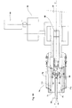
- the rolling mill according to the embodiment of the present invention shown in figure 1 is identified by the reference numeral 100 and essentially comprises a rolling mill section (or bench) 10 comprising mill stands and/or rolling dies 11 arranged in succession and each forming a passage.
- a rolling mill section (or bench) 10 comprising mill stands and/or rolling dies 11 arranged in succession and each forming a passage.
- mill stands and/or dies 11 of a different type e.g. idle and/or motorized rolls mill stands; being the mill stands and/or dies of known type, and being the rolling methods also of known, a detailed description is omitted for the sake of brevity.
- tubular elements in particular seamless, are made by means of the rolling mill 100 by passing a tubular blank with through cavity 21 fitted onto the end portion 22 of a mandrel 20 through the mill stands and/or dies 11 in succession, according to substantially known methods and therefore not described in detail.
- the rolling mill 100 is equipped with moving means which comprise a traction bar 40 fixed to a toothed bar 45 on which one or more pinions 66 engage, which are turned by means of a power source 64 (e.g. an electric motor) by means of a transmission 65.
- a power source 64 e.g. an electric motor
- the end of the traction bar 40 opposite to the toothed bar 45 is also equipped with a switchable operating header 30 and suited respectively to hook and unhook a shank 23 which is integral with the end portion 22 of the mandrel 20 ( figure 2 ), in particular engaged by screwing into a blind cavity threaded of the mandrel 20.
- the switching method of the operating header 30 will be described below with reference to other figures, in which in all cases, with reference to figure 1 , the methods and main steps of processing of the rolling mill 100 can be summarized as follows.
- the starting situation is the one shown in figure 1a , i.e. in which the traction bar 40 is in retracted position (all right with reference to the figure) relative to the bench 10 and the header 30 is in the closed configuration; it will be apparent from the following description that the situation in figure 1a substantially coincides with the final situation at the end of a rolling cycle.
- the mandrel 20, with the blank 21 fitted thereon as described above is positioned at the bench 10, on the opposite side with respect to the traction bar 40, where during the next step ( figure 1b ) the bar 40 with the header 30 still in the closed configuration, is firstly approached to the bench 10 (by rotating the pinions 66) and progressively introduced into the bench 10, i.e.
- Figure 1c shows the header 30 at the outlet from the bench 10 where, during this step, the header 30, exiting from the bench 10, is automatically switched from the closed configuration to the open configuration (see also the following description). Then ( figure 1d ), the header 30 is further approached to the shank 23, where the protruding portion of the shank 23 is located in the inner space defined by the header 30, precisely in the open configuration. Afterwards, the header 30 is switched, still automatically, from the open configuration to the closed configuration, whereby completing the latching of the shank 23 and thus of the mandrel 20.
- the header 30 is again switched automatically from the closed configuration to the open configuration, in this way releasing (unhooking) the shank 23 and thus the mandrel 20 with the tubular element fitted thereon.
- the mandrel-tubular element assembly is moved (according to methods substantially known and therefore not described in detail), in particular repositioned in misaligned position with respect to the bar 40, to finally be sent to successive final operations, such as for example the removal of the mandrel 20 and/or the finishing operations of the tubular element.
- the rolling cycle has ended and the next cycle can be started, in particular switching the header 30 again from the open configuration to the closed configuration and thus repeating the steps and/or processes shown in figures from 1a to 1h.
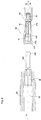
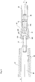
- figure 2 shows the header 30 (fixed to the end portion of the traction bar 40, the tang 23 integral to the end portion 22 of the mandrel 20, and blank 21 fitted onto the mandrel 20, in particular crimped onto the mandrel 20 to avoid sliding of the blank 21 along the mandrel 20 during the rolling operations described above, and to define a through opening for the shank 23.
- the header 30 comprises a plurality of rocker arms or petals 31 (three in number, in the embodiment shown, even though the number of the petals 31 may vary according to requirements and/or circumstances), each of the petals 31 being hinged on a central carrier bar 43, fixed in turn to the end portion of the traction bar 40, in particular engaged by screwing in a blank threaded housing of the bar 40, according to methods substantially similar to those previously described for fixing of the shank 23 to the end portion 22 of the mandrel 20.
- each of the petals 31 can rotate about a rotation axis substantially perpendicular to the longitudinal axis of symmetry of the central carrier bar 43.
- each of the petals 31 is shaped so as to define an inner recess 310 and comprises a hook-shaped end portion 311, where an end flange 430 fixed to the carrier bar 43 is housed in the inner space defined by the petals 31.
- the shank 23 also comprises an end flange 230, where it can be inferred that by closing the header 30 on the shank 23, the flange 230 is housed in the inner space defined by the petals 31, and thus engaged by the hook-shaped end 311 of each of the petals 31 ( figures 4 and 5 ).
- a tubular jacket 50 is provided, inside which the traction bar 40, the carrier bar 43 (partially) and the end portions of the petals 31 opposite to the hook-shaped end portions 311 are housed.
- the tubular jacket 50 can translate with respect to the traction bar 40 (and thus with respect to the carrier bar 43 and ultimately to the header 30) in the two opposite translation directions (from the right leftwards and from the left rightwards, with respect to figures and according to methods described in detail below), where the end portion of the jacket 50 in which the partially housed petals 31 has an inner annular protrusion 51 adapted to engage, during the translation of the jacket 50, with corresponding outer recesses 312 of the petals 31, each petal 31 thus presenting a corresponding outer recess 312.
- reference numeral 60 identifies a switching station comprising a hollow main body 610 inside which the traction bar 40 and the jacket 50 can slide in the translation according to the methods described above.
- the fixed station 60 is positioned in the immediate vicinity of the bench 10 and is provided for switching the header from the closed configuration to the open configuration and from the open configuration to the closed configuration during the steps of the rolling process described above and diagrammatically shown in Figures 1c and 1d .
- the header 30 is then positioned immediately outside the bench 10, on the opposite side with respect to the station 60 ( figure 1c ), but still in the closed configuration.
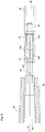
- One or more contrast elements 611 are positioned inside the main body 610, each defining a contrast surface or engagement 61.
- the contrast elements 611 can be switched by means of a linkage system 62 (which can be activated, for example, by hydraulic pistons or the like) between two end positions, in particular between a first end position (closed, figure 6 ) in which they are completely housed in the inner space defined by the hollow body 610 to restrict said inner space, and a second position of open end ( figure 8 ), in which the opposing elements 611 are retracted toward the outside of the hollow body 610 with respect to the position in figures 6 and 7 . In the open position in figure 8 , the elements 611 are then placed at a distance greater than the mutual distance at which they are arranged in the closed configuration in figures 6 and 7 .
- a linkage system 62 which can be activated, for example, by hydraulic pistons or the like
- each rocker arm 80 in the connection zone between the traction bar 40 and the toothed bar 45, in particular on the toothed bar 45, are hinged (each in a fulcrum F) rocker arms 80, each of which can rotate in the two opposite rotation directions indicated by the double arrows in Figure 6 . Furthermore, the end portion 81 of each rocker arm 80 is fixed to a corresponding transmission arm 83, in turn interposed between the jacket 50 and the respective rocker arm 80.
- the inverse switching of the header 30 from the open configuration to the closed configuration is achieved by actuating the levers 62 and the respective backward movement of the engagement surfaces 61, ultimately in repositioning them from the closed position in figure 6 to the open position or retracted position in figure 8 .
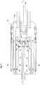
- a second switching unit 70 is provided, the latter positioned near the pinions 66, as shown in figure 1 and in figures 9 and 10 .
- Station 70 is entirely similar to station 60 and so detailed description will be omitted for the sake of brevity. It is worth noting that in figures 9 and 10 , the component parts of the station 70 corresponding to the component parts of the station 60 shown in figures from 6 to 8 and identified therein with reference numbers such as, for example, 60, 62, 610 or the like, in figures 9 and 10 are identified by reference numerals 70, 72, 710 etc. respectively.
- the rolling mill according to the present invention allows a considerable simplification of the system, where the rolling mill according to the present invention does not require the installation of the guides and related sliding rails, and therefore of the corresponding anchorages for containing the mandrel and the push bar.
- foundations are not required under the mill for rack system (pinions 66 and toothed bar 45 and respective power source 64 and possibly the transmission 65) because the toothed bar 45 can slide on the surface.
- the toothed bar 45 of rack works in line with the rolling bench 10 instead from underneath, as in the case of traditional push rolling mills, with obvious advantages in terms of cost reduction, mechanical and plant engineering simplification, as well as in terms of accessibility for maintenance operations.
- the rolling mill according to the present invention also allows to obtain a considerable improvement of the machining tolerances of the tubular elements as the rolling mill is self-centering and therefore allows to eliminate the effect of twisting of the mandrel. With the rolling mill according to the present invention are also obtained improved efficiency because the rolling mill allows the reduction of downtime, where for example it is desired to vary the diameter of the produced tubes, the time required for changing the mandrel (from a mandrel of one diameter to a mandrel of a different diameter) is reduced by 24-48 h at 0.5 h.
- the operating head (30) may be replaced by other devices, such as a screw or, for example, a bayonet coupling, which allows to provide a connection between the actuating means and the mandrel (20).
Landscapes
- Engineering & Computer Science (AREA)
- Mechanical Engineering (AREA)
- Metal Rolling (AREA)
- Reduction Rolling/Reduction Stand/Operation Of Reduction Machine (AREA)
- Forging (AREA)
Claims (11)
- Walzwerk zum Walzen von hohlen oder in allen Fällen konkaven stabförmigen Körpern, wobei das Walzwerk einen Walzabschnitt (10) mit mehreren nacheinander angeordneten Walzgerüsten und/oder Walzwerkzeugen (11) umfasst, um eine Walzachse Y zu definieren, wobei das Walzwerk ferner ein Bewegungsmittel zum Bewegen eines Dorns (20) und eines Hohlrohlings (21), der an einem Endabschnitt (22) des Dorns (20) angebracht ist, entlang der Walzachse Y und nacheinander durch die Walzgerüste oder Walzwerkzeuge (11) umfasst; dadurch gekennzeichnet, dass das Bewegungsmittel so strukturiert ist, dass es den Dorn (20) und den Rohling (21) entlang einer Walzrichtung parallel zur Walzachse Y und nacheinander durch die Walzgerüste oder Walzwerkzeuge (11) durch Anlegen einer Traktion auf den Dorn (20) bewegt.
- Walzwerk nach Anspruch 1, dadurch gekennzeichnet, dass das Bewegungsmittel einen eingreifenden Betätigungskopf (30) umfasst, der zwischen einer ersten Freigabekonfiguration und einer zweiten Eingriffskonfiguration schaltbar ist und dazu ausgelegt ist, einen mit dem Endabschnitt (22) des Dorns (20) integralen Schaft (23) in Eingriff zu bringen und alternativ freizugeben, wobei, wenn der Betätigungskopf (30) in der zweiten Eingriffskonfiguration ist und am Schaft (23) in Eingriff steht, die Bewegung des eingreifenden Betätigungskopfes (30) entlang einer Richtung parallel zur Walzachse Y dazu führt, dass der Dorn (20) und der Rohling (21) entlang der Walzachse Y und nacheinander durch die Walzgerüste oder Walzwerkzeuge (11) verschoben werden.
- Walzwerk nach Anspruch 2, dadurch gekennzeichnet, dass der eingreifende Betätigungskopf (30) mindestens einen ersten Kipphebel (31) umfasst, der zum Schalten ausgelegt ist, um zwischen einer ersten Position und einer zweiten Position zu schwenken, und dass das Schalten des mindestens einen ersten Kipphebels (31) von der ersten Position in die zweite Position dazu führt, dass der Betätigungskopf (30) von der ersten Freigabekonfiguration in die zweite Eingriffskonfiguration geschaltet wird, während das Schalten des mindestens einen ersten Kipphebels (31) von der zweiten Position zu der ersten Position führt dazu, dass der Betätigungskopf (30) von der zweiten Eingriffskonfiguration in die erste Freigabekonfiguration geschaltet wird.
- Walzwerk nach Anspruch 3, dadurch gekennzeichnet, dass es ein Schaltmittel zum Schalten des mindestens einen ersten Kipphebels (31) abwechselnd zwischen der ersten und der zweiten Position umfasst.
- Walzwerk nach Anspruch 4, dadurch gekennzeichnet, dass der mindestens eine erste Kipphebel (31) an einem Punkt angelenkt ist, der in eine Traktionsstange (40) des Bewegungsmittels integriert ist, dass die Traktionsstange (40) zumindest teilweise in einem rohrförmigen Mantel (50) untergebracht ist, der in Bezug auf die Stange (40) verschoben werden kann, und dass die Translation des rohrförmigen Mantels (50) in Bezug auf die Traktionsstange (40) in einem ersten Translationssinn dazu führt, dass der mindestens eine erste Kipphebel (31) von der ersten Position in die zweite Position geschaltet wird, während die Translation des rohrförmigen Mantels (50) in Bezug auf die Traktionsstange (40) in einem zweiten Translationssinn, der dem ersten Translationssinn entgegengesetzt ist, dazu führt, dass der mindestens eine erste Kipphebel (31) von der zweiten Position in die erste Position geschaltet wird.
- Walzwerk nach Anspruch 5, dadurch gekennzeichnet, dass es ein erstes Translationsmittel zur Translation des rohrförmigen Mantels (50) in Bezug auf die Traktionsstange (40) in dem ersten Translationssinn umfasst.
- Walzwerk nach Anspruch 6, dadurch gekennzeichnet, dass das erste Translationsmittel eine erste feste Schaltstation (60) umfasst, die mindestens eine erste Eingriffsfläche (61) und mindestens einen zweiten Kipphebel (80) definiert, der an einem Punkt einteilig mit der Traktionsstange (40) angelenkt ist, wobei die Translation der Traktionsstange (40) entlang einer Translationsrichtung parallel zur Walzrichtung und in einem ersten Translationssinn dazu führt, dass die mindestens eine erste Eingriffsfläche (61) durch den mindestens einen zweiten Kipphebel (80) geschaltet wird und der mindestens eine zweite Kipphebel (80) von einer ersten Position in eine zweite Position geschaltet wird, und dass das Schalten des mindestens einen zweiten Kipphebels (80) von der ersten Position in die zweite Position dazu führt, dass der rohrförmige Mantel (50) in Bezug auf die Stange (40) in dem zweiten Translationssinn, der dem ersten Translationssinn entgegengesetzt ist, verschoben wird und somit der Kopf (30) zwischen der zweiten Eingriffskonfiguration und der ersten Freigabekonfiguration geschaltet wird.
- Walzwerk nach Anspruch 7, dadurch gekennzeichnet, dass das erste Translationsmittel ein Mittel (62) zum Schalten der mindestens einen ersten Eingriffsfläche (61) der ersten festen Station (60) in die Freigabeposition durch den mindestens einen zweiten Kipphebel (80) umfasst, und dass das erste Translationsmittel ein elastisches Mittel (90) zur automatischen Translation des rohrförmigen Mantels (50) in dem ersten Translationssinn umfasst, wenn die mindestens eine erste Eingriffsfläche (61) der ersten festen Station (60) von dem mindestens einen zweiten Kipphebel (80) freigegeben ist.
- Walzwerk nach einem der Ansprüche 1 bis 8, dadurch gekennzeichnet, dass es ein zweites Translationsmittel zur Translation des rohrförmigen Mantels (50) in Bezug auf die Traktionsstange (40) in dem zweiten Translationssinn umfasst.
- Walzwerk nach Anspruch 9, dadurch gekennzeichnet, dass das zweite Translationsmittel eine zweite feste Schaltstation (70) umfasst, die mindestens eine zweite Eingriffsfläche (71) definiert, wobei die Translation der Traktionsstange (40) entlang einer Translationsrichtung parallel zu der Walzrichtung und in einem zweiten Translationssinn entgegengesetzt zu dem ersten Translationssinn zum Eingriff der mindestens einen zweiten Eingriffsfläche (71) durch den mindestens einen zweiten Kipphebel (80) führt, und dass der mindestens eine zweite Kipphebel (80) von der ersten Position in die zweite Position geschaltet wird, und dass das Schalten des mindestens einen zweiten Kipphebels (80) von der ersten Position in die zweite Position dazu führt, dass der rohrförmigen Mantel (50) in dem zweiten Translationssinn entgegengesetzt zu dem zweiten Translationssinn verschoben wird und somit der Kopf (30) zwischen der zweiten Eingriffskonfiguration und der ersten Freigabekonfiguration geschaltet wird.
- Walzwerk nach Anspruch 10, dadurch gekennzeichnet, dass das zweite Translationsmittel ein Mittel (72) zum Schalten der mindestens einen zweiten Eingriffsfläche (71) der zweiten festen Station (70) in die Freigabeposition durch den mindestens einen zweiten Kipphebel (80) umfasst, und dass, wenn die mindestens eine zweite Eingriffsfläche (71) der zweiten festen Station (70) von dem mindestens einen zweiten Kipphebel (80) freigegeben ist, die Wirkung des elastischen Mittels (90) zu einer automatischen Translation des rohrförmigen Mantels (50) in dem ersten Translationssinn führt.
Priority Applications (2)
| Application Number | Priority Date | Filing Date | Title |
|---|---|---|---|
| HRP20211150TT HRP20211150T1 (hr) | 2017-03-01 | 2018-03-01 | Valjaonica namijenjena valjanju šupljih ili, u svim slučajevima, udubljenih štapastih tijela |
| PL18715253T PL3589429T3 (pl) | 2017-03-01 | 2018-03-01 | Walcarka do walcowania pustych w środku lub, w każdym razie, wklęsłych produktów w kształcie pręta |
Applications Claiming Priority (2)
| Application Number | Priority Date | Filing Date | Title |
|---|---|---|---|
| IT102017000023064A IT201700023064A1 (it) | 2017-03-01 | 2017-03-01 | Laminatoio per la laminazione di elementi astiformi cavi o comunque concavi |
| PCT/IB2018/051307 WO2018158720A1 (en) | 2017-03-01 | 2018-03-01 | Rolling mill for rolling hollow or, in all cases, concave rod-shaped bodies |
Publications (2)
| Publication Number | Publication Date |
|---|---|
| EP3589429A1 EP3589429A1 (de) | 2020-01-08 |
| EP3589429B1 true EP3589429B1 (de) | 2021-04-28 |
Family
ID=59521312
Family Applications (1)
| Application Number | Title | Priority Date | Filing Date |
|---|---|---|---|
| EP18715253.3A Active EP3589429B1 (de) | 2017-03-01 | 2018-03-01 | Walzwerk zum walzen von hohlen oder, in allen fällen, konkaven stabförmigen körpern |
Country Status (10)
| Country | Link |
|---|---|
| US (1) | US11154920B2 (de) |
| EP (1) | EP3589429B1 (de) |
| CN (1) | CN110621420B (de) |
| ES (1) | ES2884050T3 (de) |
| HR (1) | HRP20211150T1 (de) |
| IT (1) | IT201700023064A1 (de) |
| PL (1) | PL3589429T3 (de) |
| RU (1) | RU2740568C1 (de) |
| SA (1) | SA519402540B1 (de) |
| WO (1) | WO2018158720A1 (de) |
Families Citing this family (3)
| Publication number | Priority date | Publication date | Assignee | Title |
|---|---|---|---|---|
| DE102021204129A1 (de) * | 2020-08-12 | 2022-02-17 | Sms Group Gmbh | Vorrichtung und Verfahren zum Handhaben von Dornstangen in einem Rohrwalzwerk |
| MX2024006183A (es) * | 2021-11-26 | 2024-06-11 | Sms Group Gmbh | Sistema para retener una varilla de mandril en una fresa de laminacion de tuberia, y metodo de funcionamiento de dicho sistema. |
| DE102022202679A1 (de) | 2021-11-26 | 2023-06-01 | Sms Group Gmbh | System und Verfahren zum Betreiben des Systems |
Citations (1)
| Publication number | Priority date | Publication date | Assignee | Title |
|---|---|---|---|---|
| CN201603742U (zh) * | 2010-03-04 | 2010-10-13 | 山西创奇实业有限公司 | 一种用于定减径机组的拉力芯棒装置 |
Family Cites Families (24)
| Publication number | Priority date | Publication date | Assignee | Title |
|---|---|---|---|---|
| US3118329A (en) * | 1964-01-21 | Tube-mandrel support | ||
| US1758413A (en) * | 1928-04-05 | 1930-05-13 | Ralph C Stiefel | Mandrel-bar-supporting apparatus for piercing mills |
| US2048925A (en) * | 1933-10-19 | 1936-07-28 | Diescher Tube Mills Inc | Tube manufacturing apparatus |
| US2569104A (en) * | 1946-03-09 | 1951-09-25 | Aetna Standard Eng Co | Mandrel bar support |
| DE1280187B (de) * | 1962-12-29 | 1968-10-17 | Schloemann Ag | Einrichtung zum Einstossen des Dornes und der Luppen bei kontinuierlichen Rohrwalzwerken |
| US3654794A (en) * | 1969-03-07 | 1972-04-11 | Atomic Energy Commission | Drawbench |
| GB2019281B (en) * | 1978-03-17 | 1982-06-16 | Metcalfe J | Planetary mill |
| US4289011A (en) * | 1978-11-17 | 1981-09-15 | Nippon Steel Corporation | Continuous pipe rolling process |
| SU1022760A1 (ru) * | 1978-12-15 | 1983-06-15 | Днепропетровский Ордена Трудового Красного Знамени Металлургический Институт | Способ продольной прокатки труб |
| IT1110926B (it) * | 1979-02-07 | 1986-01-13 | Innocenti Santeustacchio Spa | Metodo ed apparecchiatura per il controllo del movimento del mandrino in un laminatoio continuo a mandrino trattenuto |
| FR2483808A1 (fr) * | 1980-06-06 | 1981-12-11 | Vallourec | Banc de retenue de mandrin pour le mandrin qui porte un tube dans un laminoir |
| DE3113119A1 (de) * | 1981-03-27 | 1982-10-14 | Mannesmann AG, 4000 Düsseldorf | Dornstangen haltevorrichtung |
| JPS58116908A (ja) * | 1981-12-30 | 1983-07-12 | Nippon Steel Corp | 管の連続圧延機入側装置 |
| DE3405641A1 (de) * | 1984-02-17 | 1985-08-22 | Schumag Gmbh, 5100 Aachen | Verfahren zum ziehen eines nahtlosen metallrohres |
| JPS61154704A (ja) * | 1984-12-28 | 1986-07-14 | Nippon Steel Corp | 鋼管の圧延方法 |
| CN88211512U (zh) * | 1988-03-14 | 1988-12-28 | 韩湘明 | 冷拉精轧管机 |
| SU1715455A1 (ru) * | 1989-01-12 | 1992-02-28 | А.К. Зимин | Способ винтовой прошивки |
| CN1019877C (zh) * | 1990-07-11 | 1993-01-27 | 北京科技大学 | 长芯棒滚模拔轧圆管工艺 |
| DE4041668A1 (de) * | 1990-12-22 | 1992-07-02 | Walter E Spaeth | Verfahren zum biegen von metall-hohlprofilen und vorrichtung zur ausuebung des verfahrens |
| AU2003257352A1 (en) * | 2003-09-05 | 2005-03-29 | Ernst Grob Ag | Method and device for producing at least partially profiled tubes |
| IT1395593B1 (it) * | 2009-06-29 | 2012-10-16 | Danieli Off Mecc | Procedimento di laminazione e relativo laminatoio longitudinale multi gabbia di tipo trattenuto e continuo per corpi cavi |
| EP2878390B1 (de) * | 2012-07-24 | 2018-01-31 | Nippon Steel & Sumitomo Metal Corporation | Herstellungsverfahren für nahtloses metallrohr |
| CN103971768B (zh) * | 2014-05-05 | 2016-08-31 | 华中科技大学 | 一种基于畸变能密度理论的燃料棒更换机械手 |
| CN104384192B (zh) * | 2014-11-14 | 2016-07-06 | 北京京诚之星科技开发有限公司 | 拉管机和无缝管轧制方法 |
-
2017
- 2017-03-01 IT IT102017000023064A patent/IT201700023064A1/it unknown
-
2018
- 2018-03-01 US US16/485,597 patent/US11154920B2/en active Active
- 2018-03-01 PL PL18715253T patent/PL3589429T3/pl unknown
- 2018-03-01 WO PCT/IB2018/051307 patent/WO2018158720A1/en not_active Ceased
- 2018-03-01 EP EP18715253.3A patent/EP3589429B1/de active Active
- 2018-03-01 RU RU2019130890A patent/RU2740568C1/ru active
- 2018-03-01 CN CN201880014789.2A patent/CN110621420B/zh active Active
- 2018-03-01 HR HRP20211150TT patent/HRP20211150T1/hr unknown
- 2018-03-01 ES ES18715253T patent/ES2884050T3/es active Active
-
2019
- 2019-08-26 SA SA519402540A patent/SA519402540B1/ar unknown
Patent Citations (1)
| Publication number | Priority date | Publication date | Assignee | Title |
|---|---|---|---|---|
| CN201603742U (zh) * | 2010-03-04 | 2010-10-13 | 山西创奇实业有限公司 | 一种用于定减径机组的拉力芯棒装置 |
Also Published As
| Publication number | Publication date |
|---|---|
| EP3589429A1 (de) | 2020-01-08 |
| HRP20211150T1 (hr) | 2021-10-15 |
| PL3589429T3 (pl) | 2021-12-13 |
| CN110621420B (zh) | 2022-01-04 |
| WO2018158720A1 (en) | 2018-09-07 |
| RU2740568C1 (ru) | 2021-01-15 |
| CN110621420A (zh) | 2019-12-27 |
| US11154920B2 (en) | 2021-10-26 |
| ES2884050T3 (es) | 2021-12-10 |
| US20200009625A1 (en) | 2020-01-09 |
| IT201700023064A1 (it) | 2018-09-01 |
| SA519402540B1 (ar) | 2022-04-04 |
Similar Documents
| Publication | Publication Date | Title |
|---|---|---|
| US8382601B2 (en) | Method and device for manufacturing fastenings or fasteners with radial outer contours, especially screws or threaded bolts | |
| US11154920B2 (en) | Rolling mill for rolling concave, rod-shaped bodies | |
| DE4390874C1 (de) | Verfahren und Vorrichtung zur Herstellung von insbesondere als Bits gestalteten Schraubwerkzeugen in Kreuzschlitzform oder dergleichen | |
| EP2416901A1 (de) | Herstellungsverfahren von rohrmaterial | |
| EP1986801A1 (de) | Verfahren und vorrichtung zum herstellen eines ausschnittes oder durchbruchs in der wandung eines nach dem innenhochdruck-umformverfahren ausgebildeten bauteils | |
| CN102170981A (zh) | 用于在空心金属工件上非切削制作外螺纹的方法和装置 | |
| SK285010B6 (sk) | Spôsob výroby podlhovastého hriadeľa s väčším počtom vačiek, najmä vačkového hriadeľa a zariadenie na vykonávanie tohto spôsobu | |
| EP3736061B1 (de) | Feinschneidesystem und verfahren zum betreiben desselben | |
| EP3115126B1 (de) | Bearbeitungszange | |
| EP3025802B1 (de) | Vorrichtung und Verfahren zum Drückwalzen von Werkstücken | |
| CN101722203A (zh) | 高效金属挤压机 | |
| RU133438U1 (ru) | Станок для гибки труб | |
| DE69419206T2 (de) | Verfahren und Vorrichtung zum Herstellen eines metallischen Teils | |
| DE102014212732B4 (de) | Verfahren und Anstauchvorrichtung zum Herstellen von abgesetzten Werkstücken, wie Wellen oder Stäbe | |
| DE2716298A1 (de) | Huellenglied-stosseinrichtung fuer ein stopfenwalzenwerk und verfahren zum betreiben derselben | |
| DE102011013441B4 (de) | Biegevorrichtung sowie Verfahren zum Biegen eines Langprofils, insbesondere eines Rohres sowie Biegeanlage zur dreidimensionalen Formgebung eines Langprofils mit wenigstens zwei Biegevorrichtungen | |
| US5247821A (en) | Extruding press and method for its feeding | |
| US3021003A (en) | Extrusion device | |
| EP1951457B1 (de) | Verfahren und vorrichtung zum ausblasen und/oder besprühen von gesenken von schmiedepressen | |
| US20070017267A1 (en) | Apparatus and method for performing a hydroforming process | |
| EP0279014A1 (de) | Verfahren zur Herstellung von stangenförmigen Körpern mit mindestens einer einseitigen Endverdickung | |
| DE10063154B4 (de) | Schmiedepresse mit Stellvorrichtung auf Matrizenseite | |
| EP3525951B1 (de) | Formpresse mit biegeschwert | |
| GB1585692A (en) | Method of operating an extrusion press and apparatus therefor | |
| EP2221127B1 (de) | Verfahren zur Herstellung von ringförmigen Bauteilen |
Legal Events
| Date | Code | Title | Description |
|---|---|---|---|
| STAA | Information on the status of an ep patent application or granted ep patent |
Free format text: STATUS: UNKNOWN |
|
| STAA | Information on the status of an ep patent application or granted ep patent |
Free format text: STATUS: THE INTERNATIONAL PUBLICATION HAS BEEN MADE |
|
| PUAI | Public reference made under article 153(3) epc to a published international application that has entered the european phase |
Free format text: ORIGINAL CODE: 0009012 |
|
| STAA | Information on the status of an ep patent application or granted ep patent |
Free format text: STATUS: REQUEST FOR EXAMINATION WAS MADE |
|
| 17P | Request for examination filed |
Effective date: 20190927 |
|
| AK | Designated contracting states |
Kind code of ref document: A1 Designated state(s): AL AT BE BG CH CY CZ DE DK EE ES FI FR GB GR HR HU IE IS IT LI LT LU LV MC MK MT NL NO PL PT RO RS SE SI SK SM TR |
|
| AX | Request for extension of the european patent |
Extension state: BA ME |
|
| DAV | Request for validation of the european patent (deleted) | ||
| DAX | Request for extension of the european patent (deleted) | ||
| GRAP | Despatch of communication of intention to grant a patent |
Free format text: ORIGINAL CODE: EPIDOSNIGR1 |
|
| STAA | Information on the status of an ep patent application or granted ep patent |
Free format text: STATUS: GRANT OF PATENT IS INTENDED |
|
| INTG | Intention to grant announced |
Effective date: 20201106 |
|
| GRAS | Grant fee paid |
Free format text: ORIGINAL CODE: EPIDOSNIGR3 |
|
| GRAA | (expected) grant |
Free format text: ORIGINAL CODE: 0009210 |
|
| STAA | Information on the status of an ep patent application or granted ep patent |
Free format text: STATUS: THE PATENT HAS BEEN GRANTED |
|
| AK | Designated contracting states |
Kind code of ref document: B1 Designated state(s): AL AT BE BG CH CY CZ DE DK EE ES FI FR GB GR HR HU IE IS IT LI LT LU LV MC MK MT NL NO PL PT RO RS SE SI SK SM TR |
|
| REG | Reference to a national code |
Ref country code: GB Ref legal event code: FG4D |
|
| REG | Reference to a national code |
Ref country code: CH Ref legal event code: EP |
|
| REG | Reference to a national code |
Ref country code: AT Ref legal event code: REF Ref document number: 1386526 Country of ref document: AT Kind code of ref document: T Effective date: 20210515 |
|
| REG | Reference to a national code |
Ref country code: DE Ref legal event code: R096 Ref document number: 602018016229 Country of ref document: DE |
|
| REG | Reference to a national code |
Ref country code: IE Ref legal event code: FG4D |
|
| REG | Reference to a national code |
Ref country code: RO Ref legal event code: EPE Ref country code: HR Ref legal event code: TUEP Ref document number: P20211150T Country of ref document: HR |
|
| REG | Reference to a national code |
Ref country code: LT Ref legal event code: MG9D |
|
| REG | Reference to a national code |
Ref country code: HR Ref legal event code: T1PR Ref document number: P20211150 Country of ref document: HR |
|
| REG | Reference to a national code |
Ref country code: SK Ref legal event code: T3 Ref document number: E 38095 Country of ref document: SK |
|
| PG25 | Lapsed in a contracting state [announced via postgrant information from national office to epo] |
Ref country code: FI Free format text: LAPSE BECAUSE OF FAILURE TO SUBMIT A TRANSLATION OF THE DESCRIPTION OR TO PAY THE FEE WITHIN THE PRESCRIBED TIME-LIMIT Effective date: 20210428 Ref country code: LT Free format text: LAPSE BECAUSE OF FAILURE TO SUBMIT A TRANSLATION OF THE DESCRIPTION OR TO PAY THE FEE WITHIN THE PRESCRIBED TIME-LIMIT Effective date: 20210428 Ref country code: NL Free format text: LAPSE BECAUSE OF FAILURE TO SUBMIT A TRANSLATION OF THE DESCRIPTION OR TO PAY THE FEE WITHIN THE PRESCRIBED TIME-LIMIT Effective date: 20210428 Ref country code: BG Free format text: LAPSE BECAUSE OF FAILURE TO SUBMIT A TRANSLATION OF THE DESCRIPTION OR TO PAY THE FEE WITHIN THE PRESCRIBED TIME-LIMIT Effective date: 20210728 |
|
| PG25 | Lapsed in a contracting state [announced via postgrant information from national office to epo] |
Ref country code: GR Free format text: LAPSE BECAUSE OF FAILURE TO SUBMIT A TRANSLATION OF THE DESCRIPTION OR TO PAY THE FEE WITHIN THE PRESCRIBED TIME-LIMIT Effective date: 20210729 Ref country code: IS Free format text: LAPSE BECAUSE OF FAILURE TO SUBMIT A TRANSLATION OF THE DESCRIPTION OR TO PAY THE FEE WITHIN THE PRESCRIBED TIME-LIMIT Effective date: 20210828 Ref country code: LV Free format text: LAPSE BECAUSE OF FAILURE TO SUBMIT A TRANSLATION OF THE DESCRIPTION OR TO PAY THE FEE WITHIN THE PRESCRIBED TIME-LIMIT Effective date: 20210428 Ref country code: NO Free format text: LAPSE BECAUSE OF FAILURE TO SUBMIT A TRANSLATION OF THE DESCRIPTION OR TO PAY THE FEE WITHIN THE PRESCRIBED TIME-LIMIT Effective date: 20210728 Ref country code: SE Free format text: LAPSE BECAUSE OF FAILURE TO SUBMIT A TRANSLATION OF THE DESCRIPTION OR TO PAY THE FEE WITHIN THE PRESCRIBED TIME-LIMIT Effective date: 20210428 Ref country code: RS Free format text: LAPSE BECAUSE OF FAILURE TO SUBMIT A TRANSLATION OF THE DESCRIPTION OR TO PAY THE FEE WITHIN THE PRESCRIBED TIME-LIMIT Effective date: 20210428 Ref country code: PT Free format text: LAPSE BECAUSE OF FAILURE TO SUBMIT A TRANSLATION OF THE DESCRIPTION OR TO PAY THE FEE WITHIN THE PRESCRIBED TIME-LIMIT Effective date: 20210830 |
|
| REG | Reference to a national code |
Ref country code: ES Ref legal event code: FG2A Ref document number: 2884050 Country of ref document: ES Kind code of ref document: T3 Effective date: 20211210 |
|
| REG | Reference to a national code |
Ref country code: NL Ref legal event code: MP Effective date: 20210428 |
|
| PG25 | Lapsed in a contracting state [announced via postgrant information from national office to epo] |
Ref country code: CZ Free format text: LAPSE BECAUSE OF FAILURE TO SUBMIT A TRANSLATION OF THE DESCRIPTION OR TO PAY THE FEE WITHIN THE PRESCRIBED TIME-LIMIT Effective date: 20210428 Ref country code: DK Free format text: LAPSE BECAUSE OF FAILURE TO SUBMIT A TRANSLATION OF THE DESCRIPTION OR TO PAY THE FEE WITHIN THE PRESCRIBED TIME-LIMIT Effective date: 20210428 Ref country code: SM Free format text: LAPSE BECAUSE OF FAILURE TO SUBMIT A TRANSLATION OF THE DESCRIPTION OR TO PAY THE FEE WITHIN THE PRESCRIBED TIME-LIMIT Effective date: 20210428 Ref country code: EE Free format text: LAPSE BECAUSE OF FAILURE TO SUBMIT A TRANSLATION OF THE DESCRIPTION OR TO PAY THE FEE WITHIN THE PRESCRIBED TIME-LIMIT Effective date: 20210428 |
|
| REG | Reference to a national code |
Ref country code: DE Ref legal event code: R097 Ref document number: 602018016229 Country of ref document: DE |
|
| PLBE | No opposition filed within time limit |
Free format text: ORIGINAL CODE: 0009261 |
|
| STAA | Information on the status of an ep patent application or granted ep patent |
Free format text: STATUS: NO OPPOSITION FILED WITHIN TIME LIMIT |
|
| REG | Reference to a national code |
Ref country code: HR Ref legal event code: ODRP Ref document number: P20211150 Country of ref document: HR Payment date: 20220301 Year of fee payment: 5 |
|
| 26N | No opposition filed |
Effective date: 20220131 |
|
| PG25 | Lapsed in a contracting state [announced via postgrant information from national office to epo] |
Ref country code: IS Free format text: LAPSE BECAUSE OF FAILURE TO SUBMIT A TRANSLATION OF THE DESCRIPTION OR TO PAY THE FEE WITHIN THE PRESCRIBED TIME-LIMIT Effective date: 20210828 Ref country code: AL Free format text: LAPSE BECAUSE OF FAILURE TO SUBMIT A TRANSLATION OF THE DESCRIPTION OR TO PAY THE FEE WITHIN THE PRESCRIBED TIME-LIMIT Effective date: 20210428 |
|
| PG25 | Lapsed in a contracting state [announced via postgrant information from national office to epo] |
Ref country code: MC Free format text: LAPSE BECAUSE OF FAILURE TO SUBMIT A TRANSLATION OF THE DESCRIPTION OR TO PAY THE FEE WITHIN THE PRESCRIBED TIME-LIMIT Effective date: 20210428 |
|
| REG | Reference to a national code |
Ref country code: CH Ref legal event code: PL |
|
| GBPC | Gb: european patent ceased through non-payment of renewal fee |
Effective date: 20220301 |
|
| REG | Reference to a national code |
Ref country code: BE Ref legal event code: MM Effective date: 20220331 |
|
| PG25 | Lapsed in a contracting state [announced via postgrant information from national office to epo] |
Ref country code: LU Free format text: LAPSE BECAUSE OF NON-PAYMENT OF DUE FEES Effective date: 20220301 Ref country code: LI Free format text: LAPSE BECAUSE OF NON-PAYMENT OF DUE FEES Effective date: 20220331 Ref country code: IE Free format text: LAPSE BECAUSE OF NON-PAYMENT OF DUE FEES Effective date: 20220301 Ref country code: GB Free format text: LAPSE BECAUSE OF NON-PAYMENT OF DUE FEES Effective date: 20220301 Ref country code: CH Free format text: LAPSE BECAUSE OF NON-PAYMENT OF DUE FEES Effective date: 20220331 |
|
| PG25 | Lapsed in a contracting state [announced via postgrant information from national office to epo] |
Ref country code: BE Free format text: LAPSE BECAUSE OF NON-PAYMENT OF DUE FEES Effective date: 20220331 |
|
| REG | Reference to a national code |
Ref country code: HR Ref legal event code: ODRP Ref document number: P20211150 Country of ref document: HR Payment date: 20230220 Year of fee payment: 6 |
|
| REG | Reference to a national code |
Ref country code: AT Ref legal event code: UEP Ref document number: 1386526 Country of ref document: AT Kind code of ref document: T Effective date: 20210428 |
|
| REG | Reference to a national code |
Ref country code: HR Ref legal event code: ODRP Ref document number: P20211150 Country of ref document: HR Payment date: 20240220 Year of fee payment: 7 |
|
| PG25 | Lapsed in a contracting state [announced via postgrant information from national office to epo] |
Ref country code: MK Free format text: LAPSE BECAUSE OF FAILURE TO SUBMIT A TRANSLATION OF THE DESCRIPTION OR TO PAY THE FEE WITHIN THE PRESCRIBED TIME-LIMIT Effective date: 20210428 Ref country code: CY Free format text: LAPSE BECAUSE OF FAILURE TO SUBMIT A TRANSLATION OF THE DESCRIPTION OR TO PAY THE FEE WITHIN THE PRESCRIBED TIME-LIMIT Effective date: 20210428 |
|
| PG25 | Lapsed in a contracting state [announced via postgrant information from national office to epo] |
Ref country code: HU Free format text: LAPSE BECAUSE OF FAILURE TO SUBMIT A TRANSLATION OF THE DESCRIPTION OR TO PAY THE FEE WITHIN THE PRESCRIBED TIME-LIMIT; INVALID AB INITIO Effective date: 20180301 |
|
| PG25 | Lapsed in a contracting state [announced via postgrant information from national office to epo] |
Ref country code: MT Free format text: LAPSE BECAUSE OF FAILURE TO SUBMIT A TRANSLATION OF THE DESCRIPTION OR TO PAY THE FEE WITHIN THE PRESCRIBED TIME-LIMIT Effective date: 20210428 |
|
| REG | Reference to a national code |
Ref country code: HR Ref legal event code: ODRP Ref document number: P20211150 Country of ref document: HR Payment date: 20250218 Year of fee payment: 8 |
|
| PGFP | Annual fee paid to national office [announced via postgrant information from national office to epo] |
Ref country code: ES Payment date: 20250401 Year of fee payment: 8 |
|
| PG25 | Lapsed in a contracting state [announced via postgrant information from national office to epo] |
Ref country code: TR Free format text: LAPSE BECAUSE OF FAILURE TO SUBMIT A TRANSLATION OF THE DESCRIPTION OR TO PAY THE FEE WITHIN THE PRESCRIBED TIME-LIMIT Effective date: 20210428 |
|
| REG | Reference to a national code |
Ref country code: HR Ref legal event code: ODRP Ref document number: P20211150 Country of ref document: HR Payment date: 20260224 Year of fee payment: 9 |
|
| PGFP | Annual fee paid to national office [announced via postgrant information from national office to epo] |
Ref country code: DE Payment date: 20260327 Year of fee payment: 9 |
|
| PGFP | Annual fee paid to national office [announced via postgrant information from national office to epo] |
Ref country code: HR Payment date: 20260224 Year of fee payment: 9 Ref country code: AT Payment date: 20260327 Year of fee payment: 9 |
|
| PGFP | Annual fee paid to national office [announced via postgrant information from national office to epo] |
Ref country code: RO Payment date: 20260225 Year of fee payment: 9 Ref country code: IT Payment date: 20260319 Year of fee payment: 9 |
|
| PGFP | Annual fee paid to national office [announced via postgrant information from national office to epo] |
Ref country code: FR Payment date: 20260325 Year of fee payment: 9 |
|
| PGFP | Annual fee paid to national office [announced via postgrant information from national office to epo] |
Ref country code: PL Payment date: 20260219 Year of fee payment: 9 |
|
| PGFP | Annual fee paid to national office [announced via postgrant information from national office to epo] |
Ref country code: SK Payment date: 20260218 Year of fee payment: 9 |