EP3587941A1 - Ausseneinheit für klimaanlage - Google Patents
Ausseneinheit für klimaanlage Download PDFInfo
- Publication number
- EP3587941A1 EP3587941A1 EP17897333.5A EP17897333A EP3587941A1 EP 3587941 A1 EP3587941 A1 EP 3587941A1 EP 17897333 A EP17897333 A EP 17897333A EP 3587941 A1 EP3587941 A1 EP 3587941A1
- Authority
- EP
- European Patent Office
- Prior art keywords
- temporary fixing
- casing
- fan guard
- anchoring portion
- outdoor unit
- Prior art date
- Legal status (The legal status is an assumption and is not a legal conclusion. Google has not performed a legal analysis and makes no representation as to the accuracy of the status listed.)
- Granted
Links
Images


Classifications
-
- F—MECHANICAL ENGINEERING; LIGHTING; HEATING; WEAPONS; BLASTING
- F24—HEATING; RANGES; VENTILATING
- F24F—AIR-CONDITIONING; AIR-HUMIDIFICATION; VENTILATION; USE OF AIR CURRENTS FOR SCREENING
- F24F1/00—Room units for air-conditioning, e.g. separate or self-contained units or units receiving primary air from a central station
- F24F1/06—Separate outdoor units, e.g. outdoor unit to be linked to a separate room comprising a compressor and a heat exchanger
- F24F1/56—Casing or covers of separate outdoor units, e.g. fan guards
-
- F—MECHANICAL ENGINEERING; LIGHTING; HEATING; WEAPONS; BLASTING
- F24—HEATING; RANGES; VENTILATING
- F24F—AIR-CONDITIONING; AIR-HUMIDIFICATION; VENTILATION; USE OF AIR CURRENTS FOR SCREENING
- F24F13/00—Details common to, or for air-conditioning, air-humidification, ventilation or use of air currents for screening
- F24F13/08—Air-flow control members, e.g. louvres, grilles, flaps or guide plates
- F24F13/082—Grilles, registers or guards
- F24F13/084—Grilles, registers or guards with mounting arrangements, e.g. snap fasteners for mounting to the wall or duct
-
- F—MECHANICAL ENGINEERING; LIGHTING; HEATING; WEAPONS; BLASTING
- F24—HEATING; RANGES; VENTILATING
- F24F—AIR-CONDITIONING; AIR-HUMIDIFICATION; VENTILATION; USE OF AIR CURRENTS FOR SCREENING
- F24F13/00—Details common to, or for air-conditioning, air-humidification, ventilation or use of air currents for screening
- F24F13/20—Casings or covers
- F24F2013/205—Mounting a ventilator fan therein
Definitions
- the present invention relates to an outdoor unit for an air-conditioning apparatus and, more specifically, to a structure of attaching a fan guard.
- Patent Literature 1 describes a configuration that, in an outdoor unit, a fan guard is caused to slide along both sides of grooves on a casing from above and fitted to the grooves. With this configuration, when a top panel is attached, the fan guard is fixed, and thus fixing of the fan guard with a screw is not required.
- Patent Literature 1 Japanese Unexamined Patent Application Publication No. 2000-039186
- the fan guard cannot be attached or detached without raising the fan guard by a distance corresponding to the height of the fan guard, and space having a height corresponding to the height of the fan guard is required above the outdoor unit. For example, when an outdoor unit is suspended in a veranda of an apartment, there is a problem that no work space for attaching or detaching the fan guard is ensured.
- the present invention has been made to solve the above-described problems, and it is an object of the present invention to provide a highly reliable outdoor unit for an air-conditioning apparatus, which does not require work space above and which simplifies work in attaching a fan guard, and which reduces noise during operation.
- An outdoor unit for an air-conditioning apparatus of an embodiment of the present invention includes a casing and a fan guard.
- the casing includes a front panel and a top panel.
- the front panel has an opening.
- the fan guard is made up of a combination of a plurality of vertical bars and a plurality of horizontal bars, and covers the opening.
- the fan guard includes an upper anchoring portion and a lower anchoring portion.
- the upper anchoring portion is provided at an upper end of one of the vertical bars, located at a center, or each of upper ends of at least two of the vertical bars, located apart from each other in a right and left direction of the casing.
- the lower anchoring portion is provided at a lower end of a plurality of the vertical bars, located apart from each other in the right and left direction of the casing.
- the upper anchoring portion is provided such that the upper end is bent toward the casing and further bent upward.
- the lower anchoring portion is provided such that the lower end is bent toward the casing.
- a distal end of a lower anchoring distal end portion that is a distal end-side portion of the lower anchoring portion is bent so as to be oriented downward.
- the front panel includes an upper temporary fixing groove and a lower temporary fixing hole.
- the upper anchoring portion is inserted in the upper temporary fixing groove.
- the upper temporary fixing groove restricts movement of the upper anchoring portion in the right and left direction.
- the lower anchoring portion is inserted in the lower temporary fixing hole.
- the lower temporary fixing hole restricts movement of the lower anchoring portion in a forward direction and in a downward direction.
- the upper temporary fixing groove and the upper anchoring portion are covered with the top panel.
- the fan guard is temporarily fixed when the lower anchoring portion of the fan guard is inserted in the lower temporary fixing hole of the front panel and the upper anchoring portion is inserted in the upper temporary fixing groove, and the fan guard is fixed to the casing when the top panel is placed on the fan guard. Therefore, it is not required to fix the fan guard with a screw or raise the fan guard, and thus working space is reduced, and workability for attaching or detaching the fan guard improves.
- movement of the fan guard in the right and left direction is restricted by the lower temporary fixing hole and the upper temporary fixing groove and movement of the fan guard in the forward direction is restricted by the top panel, vibrations during operation are reduced, and also noise due to vibrations may be suppressed.
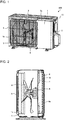
- Fig. 1 is a perspective view of the outdoor unit 100 for an air-conditioning apparatus according to Embodiment of the present invention.
- the outdoor unit 100 includes, for example, a box-shaped casing 10.
- the casing 10 includes a front panel 1 at a front side, a side panel 2 at a side, a top panel 3 at a top side, and a back panel 6.
- the back panel 6 makes up a backside and a side facing the side panel 2.
- the front panel 1 of the outdoor unit 100 has an opening 1a that serves as an air duct.
- the opening 1a is covered with a fan guard 5 at the front side from the outer side of the casing 10.
- the top panel 3 has a lid shape and has side peripheral portions 3a at its four sides.
- the side peripheral portions 3a extend downward.
- the top panel 3 covers the top side of the casing 10.
- the configuration of the casing 10 of the outdoor unit 100 is not limited to the above-described configuration, and may be changed as needed.
- the panels that make up the casing 10 of the outdoor unit 100, such as the front panel 1, may be combined and integrated. Each panel may be made up of a plurality of separate panels.
- the side where the front panel 1 of the casing 10 is disposed is defined as "front side”
- the back panel 6 side facing the front panel 1 in the casing 10 is defined as "rear side”
- the right and left sides when the front panel 1 of the casing 10 is viewed from the front are defined as "right side” and "left side”.
- the top panel 3 side of the casing 10 is defined as "upper side”
- the side where a surface facing the top panel 3 of the casing 10 is located is defined as "lower side”.
- Fig. 2 is a schematic longitudinally sectional view along a plane including a central axis of a fan 4 of the outdoor unit 100 for an air-conditioning apparatus according to Embodiment.
- the fan 4 is disposed inside the casing 10.
- a motor 8 is mounted at the center portion of the fan 4.
- the motor 8 is mounted on a fixing element 7 provided inside the casing 10.
- a heat exchanger 15 is disposed on the back panel 6 side of the fan 4 and motor 8.
- the back panel 6 has an air inlet 6a that opens along the heat exchanger 15.
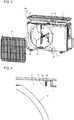
- Fig. 3 is an exploded perspective view of a state where the fan guard 5 and the top panel 3 of the outdoor unit 100 for an air-conditioning apparatus according to Embodiment are detached.
- the front panel 1 has upper temporary fixing grooves 1b above the opening 1a.
- the upper temporary fixing grooves 1b are used to temporarily fix the fan guard 5.
- the front panel 1 has lower temporary fixing holes 1c below the opening 1a.
- the upper temporary fixing grooves 1b are disposed at bilaterally symmetric locations relative to the center at two portions to the right and left of the opening 1a when the front panel 1 is viewed from the front.
- the lower temporary fixing holes 1c are disposed likewise.
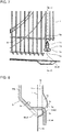
- Fig. 4 is an enlarged view of portion A in Fig. 3 and is an enlarged view of a portion around the upper temporary fixing groove 1b at the right upper side when the front panel 1 is viewed from the front.
- a portion around the upper temporary fixing groove 1b at the left upper side when the front panel 1 is viewed from the front has a similar structure to a structure bilaterally symmetric to the structure of the portion around the upper temporary fixing groove 1b of Fig. 4 .
- the upper temporary fixing groove 1b smoothly connects with a surface 1h of the front panel 1 at right and left edge portions 1d, 1e, and opens on the front of the casing.
- the right and left edge portions 1d, 1e are connected in a cylindrical shape and recessed from the surface 1h toward the backside.
- the right and left edge portions 1d, 1e form the upper temporary fixing groove 1b in a curved surface shape.
- the upper temporary fixing groove 1b is, for example, formed by plastically deforming an element such as a sheet metal that makes up the front panel 1.
- Fig. 5 is an enlarged view of portion B in Fig. 3 and is an enlarged view of a portion around the lower temporary fixing hole 1c at the right lower side when the front panel 1 is viewed from the front.
- a portion around the lower temporary fixing hole 1c at the left lower side when the front panel 1 is viewed from the front has a similar structure to a structure bilaterally symmetric to the structure of the portion around the lower temporary fixing hole 1c of Fig. 5 .
- the lower temporary fixing hole 1c is formed such that a groove 1n that is long in an up and down direction and formed at the surface 1h of the front panel 1 opens at its lower end.
- the lower temporary fixing hole 1c is made up of a lower edge 1p projecting forward and an upper edge 1q recessed rearward.
- the lower temporary fixing hole 1c is oriented upward of the casing 10 at its end.
- Fig. 6 is a perspective view illustrating the fan guard 5 of the outdoor unit 100 for an air-conditioning apparatus according to Embodiment.
- the fan guard 5 is made up of a combination of a plurality of horizontal bars 5a and a plurality of vertical bars 5b.
- the horizontal bars 5a and the vertical bars 5b are made up of, for example, wire elements.
- a plurality of the horizontal bars 5a is disposed in the up and down direction at predetermined intervals, and each of the horizontal bars 5a is provided in the right and left direction.
- a plurality of the vertical bars 5b is disposed in the right and left direction at predetermined intervals, and each of the vertical bars 5b is provided in the up and down direction.
- the horizontal bars 5a and the vertical bars 5b are provided so as to intersect at right angles with each other.
- the vertical bars 5b include first vertical bars 51b and second vertical bars 52b.
- the first vertical bars 51b are disposed at two portions located apart in the right and left direction of the casing 10.
- the second vertical bars 52b are disposed at two portions located apart in the right and left direction of the casing 10 and located closer to the center than the first vertical bars 51b.
- Each of the first vertical bars 51b has an upper anchoring portion 51b2.
- the upper anchoring portion 51b2 is bent toward the casing 10 at its upper end, and then the distal end portion of the upper anchoring portion 51b2 is bent upward.
- each of the first vertical bars 51b has a lower anchoring portion 51b5 at its lower end.
- the lower anchoring portion 51b5 is bent toward the casing 10, and then a lower anchoring distal end portion 51b4 that is the distal end portion of the lower anchoring portion 51b5 is bent downward.
- Each of the second vertical bars 52b has a contact portion 52b3 at its upper end and a contact portion 52b3 at its lower end.
- the contact portion 52b3 is bent toward the casing 10, and the distal end of the contact portion 52b3 is oriented at an angle close to a direction perpendicular to the surface 1h of the front panel 1.
- the locations of the first vertical bars 51b and the second vertical bars 52b are also not limited to the illustrated locations.
- the number of locations of the first vertical bars 51b is not limited to two, and may be one at the center or three or more in the right and left direction of the casing 10.
- the number of locations of the second vertical bars 52b is also not limited to two, and may be one at the center or may be three or more.
- the fan guard 5 may be made up of resin, not metal wires.
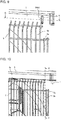
- Fig. 7 is an enlarged view of a portion around the lower anchoring portion 51b5 of the fan guard 5 of the outdoor unit 100 for an air-conditioning apparatus according to Embodiment.
- Fig. 8 is a schematic sectional view along the line C-C in Fig. 7 and illustrates a section in the front and rear direction of the casing 10 so as to pass through the center of the lower temporary fixing hole 1c.
- the portion indicated by the dashed line represents the contact portion 52b3 located on the far side of the first vertical bar 51b.
- the lower anchoring portion 51b5 is inserted in the lower temporary fixing hole 1c of the front panel 1, the distal end-side lower anchoring distal end portion 51b4 is located inside the casing 10 and is parallel to the surface 1h of the front panel 1.
- the lower anchoring distal end portion 51b4 is located rearward of the lower edge 1p of the lower temporary fixing hole 1c and forward of the upper edge 1q. Movement of the fan guard 5 in the forward direction of the casing 10 is restricted by contact between the lower anchoring distal end portion 51b4 and the lower edge 1p. At this time, a force directed from the casing 10 toward the fan guard 5 acts on the lower anchoring distal end portion 51b4.
- the contact portion 52b3 is provided at the lower end of the second vertical bar 52b.
- the contact portion 52b3 contacts with the surface 1h of the front panel 1, and restricts movement of the fan guard 5 in the rearward direction.
- a force directed from the fan guard 5 toward the casing 10 acts.
- the force that is applied to the fan guard 5 by contact of the contact portion 52b3 with the casing 10 is opposite to the force that is applied to the fan guard 5 by contact of the lower anchoring distal end portion 51b4 with the casing 10.
- Fig. 9 is an enlarged view of a portion around the upper anchoring portion 5b2 in a state where the top panel 3 of the outdoor unit 100 for an air-conditioning apparatus according to Embodiment is detached.
- Fig. 10 is an enlarged view of a portion around the upper anchoring portion 51b2 in a state where the top panel 3 of the outdoor unit 100 according to Embodiment is attached.
- the upper anchoring portion 51b2 of the fan guard 5 is plugged in the upper temporary fixing groove 1b formed in the front panel 1.
- the upper anchoring portion 51b2 is covered with the side peripheral portion 3a of the top panel 3 placed above.
- Fig. 11 is a schematic sectional view along the line D-D in Fig. 9 .
- the D-D section is a section of the casing 10, in the right and left direction, and is a section passing through the center of the upper temporary fixing groove 1b.
- Fig. 12 is a schematic sectional view along the line E-E in Fig. 10 .
- the E-E section is a section of the casing 10, in the front and rear direction, and is a section passing through the center of the upper temporary fixing groove 1b.
- the upper anchoring portion 51b2 is press-fitted in the upper temporary fixing groove 1b, and is sandwiched by the side peripheral portion 3a of the top panel 3 and the surface 1h of the front panel 1.
- the upper temporary fixing groove 1b is formed so as to have a width equal to the diameter of the wire of the upper anchoring portion 51b2, and restricts movement of the upper anchoring portion 51b2 in the right and left direction.
- the width of the upper temporary fixing groove 1b only needs to be selected as appropriate so that the upper anchoring portion 51b2 can be held. With the width less than the diameter of the wire, the upper anchoring portion 51b2 is further securely held.
- the upper temporary fixing groove 1b is formed so as to have a depth equal to the diameter of the wire of the upper anchoring portion 51b2, and restricts movement, in the front and rear direction, of the upper anchoring portion 51b2 sandwiched by the side peripheral portion 3a of the top panel 3 and the surface 1h of the front panel 1.
- a portion of the upper anchoring portion 51b2, being exposed from the opening of the upper temporary fixing groove 1b, is pressed by the side peripheral portion 3a of the top panel 3, and movement of the upper anchoring portion 51b2 in the forward direction is restricted. Movement of the upper anchoring portion 51b2 in the rearward direction is restricted by the upper temporary fixing groove 1b having a shape recessed toward the backside.
- the depth of the upper temporary fixing groove 1b only needs to be a depth that allows the upper anchoring portion 51b2 to be sandwiched by the side peripheral portion 3a of the top panel 3 and the surface 1h of the front panel 1, and may be less than the diameter of the wire.
- the upper anchoring portion 51b2 Since the upper anchoring portion 51b2 is press-fitted in the upper temporary fixing groove 1b, movement of the fan guard 5 in the right and left direction is restricted. Since the upper anchoring portion 51b2 is sandwiched by the front panel 1 and the top panel 3, movement of the fan guard 5 in the front and rear direction is restricted. Therefore, movement of the fan guard 5 due to vibrations during operation of the air-conditioning apparatus is prevented, and thus generation of noise is suppressed.
- the fan guard 5 is attached before the top panel 3 is attached to the casing 10.
- the fan guard 5 is located in front of the front panel 1. At this time, the fan guard 5 is inclined by tilting the upper ends of the upper anchoring portions 51b2 forward of the casing 10. After that, the lower anchoring distal end portions 51b4 of the lower anchoring portions 51b5 are brought close to the lower portion of the front panel 1 and inserted into the lower temporary fixing holes 1c formed in the front panel 1, and the lower anchoring portions 51b5 are engaged with the lower temporary fixing holes 1c.
- the fan guard 5 is pivoted in a direction in which the upper ends of the upper anchoring portions 51b2 are brought closer to the upper portion of the front panel 1.
- the upper anchoring portions 51b2 are moved to the locations of the upper temporary fixing grooves 1b formed in the front panel 1.
- the lower anchoring portions 51b5 contact with the lower edges 1p of the lower temporary fixing holes 1c, and movement of the lower anchoring portions 51b5 in the front and rear direction and in the downward direction is restricted. Therefore, the upper anchoring portions 51b2 move along predetermined trajectories and reliably reach the locations of the upper temporary fixing grooves 1b.
- the upper anchoring portions 51b2 are pushed in toward the front panel 1 while being caused to contact with the lower edges 1p of the upper temporary fixing grooves 1b, and fitted into the upper temporary fixing grooves 1b.
- the upper anchoring portions 51b2 are engaged with the upper temporary fixing grooves 1b.
- the lower edges 1p of the upper temporary fixing grooves 1b have a curved surface 1f. This is because, when the lower edges 1p have the curved surfaces 1f, the upper anchoring portions 51b2 move along the curved surfaces 1f and easily engage with the upper temporary fixing grooves 1b.
- the upper anchoring portions 51b2 and the lower anchoring portions 51b5 of the fan guard 5 are respectively engaged with the upper temporary fixing grooves 1b and the lower temporary fixing holes 1c, and the fan guard 5 is preliminarily fixed at a predetermined location of the casing 10. Thus, the fan guard 5 is temporarily fixed.
- the upper anchoring portions 51b2 are inserted in the upper temporary fixing grooves 1b, and movement of the fan guard 5 in the front and rear direction and in the right and left direction is restricted.
- the upper anchoring portions 51b2 of the fan guard 5 are press-fitted in the upper temporary fixing grooves 1b. Therefore, the fan guard 5 does not fall forward of the casing 10, and the fan guard 5 is kept attached to the casing 10. Hence, a worker does not need to hold the fan guard 5.
- the top panel 3 is disposed on the casing 10 to which the fan guard 5 is temporarily fixed, and the four side peripheral portions 3a of the top panel 3 are fitted to the upper portion of the casing 10.
- the top panel 3 is placed to cover the casing 10.
- the upper anchoring portions 51b2 of the fan guard 5 are sandwiched by the side peripheral portion 3a of the top panel 3 and the surface 1h of the front panel 1.
- the fan guard 5 is fixed to the casing 10. Attachment of the fan guard 5 completes.
- the fan guard 5 Since the fan guard 5 is firmly fixed by the top panel 3, a forward drop-off of the fan guard 5 at the time when a large impact acts on the casing 10 is reduced. In addition, movement of the upper anchoring portions 51b2 and the lower anchoring portions 51b5 of the fan guard 5 in the front and rear direction and in the right and left direction is restricted, thus vibrations during operation are reduced, and noise due to vibrations is reduced. Furthermore, since the fan guard 5 is fixed by disposing the top panel 3 through clearance above the casing 10 and placing the top panel 3 to cover the casing 10, space required for attachment is reduced. In addition, fastening with a screw is not required, and therefore attachment is facilitated.
- the top panel 3 is detached, and the fan guard 5 is placed in a temporary fixed state. Then, the upper anchoring portions 51b2 are pulled out from the upper temporary fixing grooves 1b, the upper end of the fan guard 5 is pivoted in a direction to move forward, and then the fan guard 5 is raised upward to pull the lower anchoring portions 51b5 out from the lower temporary fixing holes 1c. Thus, detaching of the fan guard 5 completes.
- the upper anchoring portion 51b2 and the lower anchoring portion 51b5 both are provided in the first vertical bar 51b. Instead, the upper anchoring portion 51b2 and the lower anchoring portion 51b5 may be respectively provided in different vertical bars. It is desirable that each of the set of upper anchoring portions 51b2 and the set of lower anchoring portions 51b5 be provided at bilaterally symmetric locations. This is because, with this configuration, forces that act on the fan guard 5 reach equilibrium. Furthermore, the upper anchoring portion 51b2 may be provided at least in one vertical bar located at the center.
- Fig. 13 is a schematic view illustrating the outdoor unit 100 for an air-conditioning apparatus according to a modification of Embodiment, and corresponds to a schematic sectional view along the line D-D in Fig. 9 in Embodiment.
- the outdoor unit 100 for an air-conditioning apparatus according to the modification includes protrusions 11b2 formed in the upper temporary fixing groove 11b of the front panel 1.
- the D-D section is a section of the casing 10, in the right and left direction, and is a section passing through the center of the upper temporary fixing groove 11b.
- the upper temporary fixing groove 11b has the protrusions 11b2 formed at the front side.
- Each of the protrusions 11b2 is formed at the edge of the recessed shape of the upper temporary fixing groove 11b along, for example, part of the upper temporary fixing groove 11b in a longitudinal direction or a ridge 11b1 of the edge.
- the diameter of a circle drawn by an inner wall surface 1b3 of the upper temporary fixing groove 11b and tangents of the protrusions 11b2 is equal to the diameter of the upper anchoring portion 51b2.
- the upper anchoring portion 51b2 When the upper anchoring portion 51b2 is press-fitted into the upper temporary fixing groove 11b, the upper anchoring portion 51b2 is held by the protrusions 11b2, and movement in the right and left direction and in the forward direction is restricted. With the thus configured protrusions 11b2, the upper anchoring portion 51b2 is prevented from coming off from the upper temporary fixing groove 11b. In addition, for example, even when the outdoor unit 100 is manufactured without dimensional control for press-fitting, the upper anchoring portion 51b2 is held, and movement in the right and left direction and in the front and rear direction due to vibrations is restricted.
- the upper anchoring portions 51b2 and lower anchoring portions 51b5 of the fan guard 5 are inserted into the upper temporary fixing grooves 1b and lower temporary fixing holes 1c of the front panel 1, and the fan guard 5 is temporarily fixed to the casing 10. Then, when the top panel 3 is placed on the casing 10 to which the fan guard 5 is temporarily fixed, the fan guard 5 is fixed. In a temporarily fixed state, movement of the upper anchoring portions 51b2 in the up and down direction is restricted by the upper temporary fixing grooves 1b, and movement of the lower anchoring portions 51b5 in the up and down direction and in the front and rear direction is restricted by the lower temporary fixing holes 1c.
- the upper temporary fixing groove 1b is an opening that opens on the front of the casing, and allows the upper anchoring portion 51b2 to be inserted therein when the upper anchoring portion 51b2 is pushed in. Therefore, attachment is facilitated, and a member, such as a screw, that needs to be fixed is not required.
- the upper anchoring portion 51b2 that has moved along the curved surface 1f can reach the upper temporary fixing groove 1b and engage with the upper temporary fixing groove 1b.
- the width of the upper temporary fixing groove 1b By allowing the width of the upper temporary fixing groove 1b to be equal to or less than the diameter of the upper anchoring portion 51b2, movement of the upper anchoring portion 51b2 press-fitted in the upper temporary fixing groove 1b, in the right and left direction can be restricted, and the upper anchoring portion 51b2 can be held.
- the upper anchoring portion 51b2 With the protrusions 11b2 of the upper temporary fixing groove 11b, the upper anchoring portion 51b2 is prevented from coming off from the upper temporary fixing groove 11b. In addition, even when the outdoor unit 100 is manufactured without dimensional control for press-fitting, the upper anchoring portion 51b2 is held, and movement of the upper anchoring portion 51b2 in the right and left direction and in the front and rear direction due to vibrations is restricted.
- the lower anchoring portion 51b5 contacts with the lower edge 1p when the lower anchoring portion 51b5 moves forward, and movement of the lower anchoring portion 51b5 in the forward direction is restricted.
- the contact portions 52b3 and lower anchoring distal end portions 51b4 of the fan guard 5 contact with the casing 10, and apply opposite forces to the fan guard 5. Therefore, movement of the fan guard 5 in the forward direction is restricted by the contact portions 52b3, movement of the fan guard 5 in the rearward direction is restricted by the lower anchoring portions 51b5, and movement of the fan guard 5 due to vibrations is reduced.
Landscapes
- Engineering & Computer Science (AREA)
- Chemical & Material Sciences (AREA)
- Combustion & Propulsion (AREA)
- Mechanical Engineering (AREA)
- General Engineering & Computer Science (AREA)
- Other Air-Conditioning Systems (AREA)
Applications Claiming Priority (1)
| Application Number | Priority Date | Filing Date | Title |
|---|---|---|---|
| PCT/JP2017/006908 WO2018154686A1 (ja) | 2017-02-23 | 2017-02-23 | 空気調和機の室外機 |
Publications (3)
| Publication Number | Publication Date |
|---|---|
| EP3587941A1 true EP3587941A1 (de) | 2020-01-01 |
| EP3587941A4 EP3587941A4 (de) | 2020-03-04 |
| EP3587941B1 EP3587941B1 (de) | 2022-12-28 |
Family
ID=63252457
Family Applications (1)
| Application Number | Title | Priority Date | Filing Date |
|---|---|---|---|
| EP17897333.5A Active EP3587941B1 (de) | 2017-02-23 | 2017-02-23 | Ausseneinheit für klimaanlage |
Country Status (5)
| Country | Link |
|---|---|
| US (1) | US20190368753A1 (de) |
| EP (1) | EP3587941B1 (de) |
| JP (1) | JP6808013B2 (de) |
| CN (1) | CN110291333A (de) |
| WO (1) | WO2018154686A1 (de) |
Cited By (1)
| Publication number | Priority date | Publication date | Assignee | Title |
|---|---|---|---|---|
| EP4502477A1 (de) * | 2023-08-04 | 2025-02-05 | LG Electronics Inc. | Ausseneinheit einer klimaanlage |
Families Citing this family (4)
| Publication number | Priority date | Publication date | Assignee | Title |
|---|---|---|---|---|
| JP6949247B2 (ja) * | 2018-11-08 | 2021-10-13 | 三菱電機株式会社 | 空気調和機の室外機 |
| US20220333795A1 (en) * | 2019-12-06 | 2022-10-20 | Mitsubishi Electric Corporation | Outdoor unit for air-conditioning apparatus |
| MY203986A (en) * | 2020-01-22 | 2024-07-29 | Daikin Res & Development Malaysia Sdn Bhd | A mounting structure of a grille |
| WO2023181225A1 (ja) * | 2022-03-24 | 2023-09-28 | 三菱電機株式会社 | 室外機、および冷凍サイクル装置 |
Family Cites Families (10)
| Publication number | Priority date | Publication date | Assignee | Title |
|---|---|---|---|---|
| JPH01189438A (ja) * | 1988-01-25 | 1989-07-28 | Matsushita Seiko Co Ltd | 空気調和機の羽根ガード固定装置 |
| JPH02114826U (de) * | 1989-02-21 | 1990-09-13 | ||
| JPH0510918U (ja) * | 1991-07-22 | 1993-02-12 | 株式会社富士通ゼネラル | 室外機のフアンガード取付構造 |
| JP3189263B2 (ja) * | 1994-11-01 | 2001-07-16 | 船井電機株式会社 | 室外機の熱交換器保護装置 |
| US5575622A (en) * | 1994-12-16 | 1996-11-19 | Staco, Inc. | Method and apparatus for mounting a fan guard |
| JP2000039186A (ja) | 1998-07-24 | 2000-02-08 | Mitsubishi Heavy Ind Ltd | 室外機ユニットおよび空気調和機 |
| JP5289200B2 (ja) * | 2009-06-19 | 2013-09-11 | 三菱電機株式会社 | 空気調和機用室外機 |
| DE102012020245B4 (de) * | 2012-10-11 | 2015-01-15 | Uwe Stadtmüller | Schutzvorrichtung |
| JP6041136B2 (ja) * | 2012-12-28 | 2016-12-07 | パナソニックIpマネジメント株式会社 | フラットファンガード及び室外ユニット |
| JP5984760B2 (ja) * | 2013-08-08 | 2016-09-06 | 三菱電機株式会社 | 空気調和機の室外機 |
-
2017
- 2017-02-23 EP EP17897333.5A patent/EP3587941B1/de active Active
- 2017-02-23 JP JP2019500930A patent/JP6808013B2/ja not_active Expired - Fee Related
- 2017-02-23 US US16/466,664 patent/US20190368753A1/en not_active Abandoned
- 2017-02-23 CN CN201780079594.1A patent/CN110291333A/zh active Pending
- 2017-02-23 WO PCT/JP2017/006908 patent/WO2018154686A1/ja not_active Ceased
Cited By (1)
| Publication number | Priority date | Publication date | Assignee | Title |
|---|---|---|---|---|
| EP4502477A1 (de) * | 2023-08-04 | 2025-02-05 | LG Electronics Inc. | Ausseneinheit einer klimaanlage |
Also Published As
| Publication number | Publication date |
|---|---|
| JPWO2018154686A1 (ja) | 2019-11-07 |
| EP3587941B1 (de) | 2022-12-28 |
| CN110291333A (zh) | 2019-09-27 |
| US20190368753A1 (en) | 2019-12-05 |
| WO2018154686A1 (ja) | 2018-08-30 |
| EP3587941A4 (de) | 2020-03-04 |
| JP6808013B2 (ja) | 2021-01-06 |
Similar Documents
| Publication | Publication Date | Title |
|---|---|---|
| EP3587941B1 (de) | Ausseneinheit für klimaanlage | |
| EP3128243B1 (de) | Klimaanlagen-ausseneinheit | |
| JP5950877B2 (ja) | 空気調和機の化粧パネル取付構造及び室内機 | |
| EP3524894B1 (de) | Ausseneinheit für klimatisierungsvorrichtung | |
| EP2899472A1 (de) | Innenraumeinheit für Klimaanlage mit Windschützen | |
| US10113550B2 (en) | Ventilation system and method | |
| EP2947397A2 (de) | Windrichtungseinstellungsvorrichtung einer klimaanlagenvorrichtung und klimaanlagenvorrichtung | |
| JP5507158B2 (ja) | 壁掛け型空気調和装置 | |
| EP3208548A1 (de) | Aussenmaschine für klimaanlage | |
| CN109906342B (zh) | 空调机的室外机 | |
| CN105910170B (zh) | 设备机器 | |
| JP2000065385A (ja) | 天井埋込型空気調和機 | |
| EP2980502B1 (de) | Klimaanlage | |
| CN213272877U (zh) | 柜式空调 | |
| CN215637542U (zh) | 一种空调室内机及空调器 | |
| CN210486020U (zh) | 一种面板结构及空调器 | |
| JP2009250459A (ja) | 空気調和機の室外ユニット | |
| CN205279258U (zh) | 空调柜机 | |
| JP3709874B2 (ja) | 防護グリルおよび空気調和装置の室外機 | |
| CN205156181U (zh) | 空调机的室外机 | |
| JPH10170022A (ja) | 空気調和機の室内機 | |
| JPH1019296A (ja) | 天井埋込型空気調和機 | |
| JPWO2020095402A1 (ja) | 空気調和機の室外機 | |
| JPS61280328A (ja) | 空気調和機のエアフイルタ取付装置 | |
| JP2009145018A (ja) | 空気調和装置の室外機および該空気調和装置の室外機に用いられる吸込グリル。 |
Legal Events
| Date | Code | Title | Description |
|---|---|---|---|
| STAA | Information on the status of an ep patent application or granted ep patent |
Free format text: STATUS: THE INTERNATIONAL PUBLICATION HAS BEEN MADE |
|
| PUAI | Public reference made under article 153(3) epc to a published international application that has entered the european phase |
Free format text: ORIGINAL CODE: 0009012 |
|
| STAA | Information on the status of an ep patent application or granted ep patent |
Free format text: STATUS: REQUEST FOR EXAMINATION WAS MADE |
|
| 17P | Request for examination filed |
Effective date: 20190709 |
|
| AK | Designated contracting states |
Kind code of ref document: A1 Designated state(s): AL AT BE BG CH CY CZ DE DK EE ES FI FR GB GR HR HU IE IS IT LI LT LU LV MC MK MT NL NO PL PT RO RS SE SI SK SM TR |
|
| AX | Request for extension of the european patent |
Extension state: BA ME |
|
| A4 | Supplementary search report drawn up and despatched |
Effective date: 20200204 |
|
| RIC1 | Information provided on ipc code assigned before grant |
Ipc: F24F 13/20 20060101ALI20200129BHEP Ipc: F24F 1/56 20110101AFI20200129BHEP |
|
| DAV | Request for validation of the european patent (deleted) | ||
| DAX | Request for extension of the european patent (deleted) | ||
| GRAP | Despatch of communication of intention to grant a patent |
Free format text: ORIGINAL CODE: EPIDOSNIGR1 |
|
| STAA | Information on the status of an ep patent application or granted ep patent |
Free format text: STATUS: GRANT OF PATENT IS INTENDED |
|
| INTG | Intention to grant announced |
Effective date: 20220714 |
|
| GRAS | Grant fee paid |
Free format text: ORIGINAL CODE: EPIDOSNIGR3 |
|
| GRAA | (expected) grant |
Free format text: ORIGINAL CODE: 0009210 |
|
| STAA | Information on the status of an ep patent application or granted ep patent |
Free format text: STATUS: THE PATENT HAS BEEN GRANTED |
|
| AK | Designated contracting states |
Kind code of ref document: B1 Designated state(s): AL AT BE BG CH CY CZ DE DK EE ES FI FR GB GR HR HU IE IS IT LI LT LU LV MC MK MT NL NO PL PT RO RS SE SI SK SM TR |
|
| REG | Reference to a national code |
Ref country code: GB Ref legal event code: FG4D |
|
| REG | Reference to a national code |
Ref country code: CH Ref legal event code: EP |
|
| REG | Reference to a national code |
Ref country code: DE Ref legal event code: R096 Ref document number: 602017065130 Country of ref document: DE |
|
| REG | Reference to a national code |
Ref country code: AT Ref legal event code: REF Ref document number: 1540739 Country of ref document: AT Kind code of ref document: T Effective date: 20230115 |
|
| REG | Reference to a national code |
Ref country code: IE Ref legal event code: FG4D |
|
| REG | Reference to a national code |
Ref country code: LT Ref legal event code: MG9D |
|
| PG25 | Lapsed in a contracting state [announced via postgrant information from national office to epo] |
Ref country code: SE Free format text: LAPSE BECAUSE OF FAILURE TO SUBMIT A TRANSLATION OF THE DESCRIPTION OR TO PAY THE FEE WITHIN THE PRESCRIBED TIME-LIMIT Effective date: 20221228 Ref country code: NO Free format text: LAPSE BECAUSE OF FAILURE TO SUBMIT A TRANSLATION OF THE DESCRIPTION OR TO PAY THE FEE WITHIN THE PRESCRIBED TIME-LIMIT Effective date: 20230328 Ref country code: LT Free format text: LAPSE BECAUSE OF FAILURE TO SUBMIT A TRANSLATION OF THE DESCRIPTION OR TO PAY THE FEE WITHIN THE PRESCRIBED TIME-LIMIT Effective date: 20221228 Ref country code: FI Free format text: LAPSE BECAUSE OF FAILURE TO SUBMIT A TRANSLATION OF THE DESCRIPTION OR TO PAY THE FEE WITHIN THE PRESCRIBED TIME-LIMIT Effective date: 20221228 |
|
| REG | Reference to a national code |
Ref country code: NL Ref legal event code: MP Effective date: 20221228 |
|
| REG | Reference to a national code |
Ref country code: AT Ref legal event code: MK05 Ref document number: 1540739 Country of ref document: AT Kind code of ref document: T Effective date: 20221228 |
|
| PG25 | Lapsed in a contracting state [announced via postgrant information from national office to epo] |
Ref country code: RS Free format text: LAPSE BECAUSE OF FAILURE TO SUBMIT A TRANSLATION OF THE DESCRIPTION OR TO PAY THE FEE WITHIN THE PRESCRIBED TIME-LIMIT Effective date: 20221228 Ref country code: LV Free format text: LAPSE BECAUSE OF FAILURE TO SUBMIT A TRANSLATION OF THE DESCRIPTION OR TO PAY THE FEE WITHIN THE PRESCRIBED TIME-LIMIT Effective date: 20221228 Ref country code: HR Free format text: LAPSE BECAUSE OF FAILURE TO SUBMIT A TRANSLATION OF THE DESCRIPTION OR TO PAY THE FEE WITHIN THE PRESCRIBED TIME-LIMIT Effective date: 20221228 Ref country code: GR Free format text: LAPSE BECAUSE OF FAILURE TO SUBMIT A TRANSLATION OF THE DESCRIPTION OR TO PAY THE FEE WITHIN THE PRESCRIBED TIME-LIMIT Effective date: 20230329 |
|
| PG25 | Lapsed in a contracting state [announced via postgrant information from national office to epo] |
Ref country code: NL Free format text: LAPSE BECAUSE OF FAILURE TO SUBMIT A TRANSLATION OF THE DESCRIPTION OR TO PAY THE FEE WITHIN THE PRESCRIBED TIME-LIMIT Effective date: 20221228 |
|
| PG25 | Lapsed in a contracting state [announced via postgrant information from national office to epo] |
Ref country code: SM Free format text: LAPSE BECAUSE OF FAILURE TO SUBMIT A TRANSLATION OF THE DESCRIPTION OR TO PAY THE FEE WITHIN THE PRESCRIBED TIME-LIMIT Effective date: 20221228 Ref country code: RO Free format text: LAPSE BECAUSE OF FAILURE TO SUBMIT A TRANSLATION OF THE DESCRIPTION OR TO PAY THE FEE WITHIN THE PRESCRIBED TIME-LIMIT Effective date: 20221228 Ref country code: PT Free format text: LAPSE BECAUSE OF FAILURE TO SUBMIT A TRANSLATION OF THE DESCRIPTION OR TO PAY THE FEE WITHIN THE PRESCRIBED TIME-LIMIT Effective date: 20230428 Ref country code: ES Free format text: LAPSE BECAUSE OF FAILURE TO SUBMIT A TRANSLATION OF THE DESCRIPTION OR TO PAY THE FEE WITHIN THE PRESCRIBED TIME-LIMIT Effective date: 20221228 Ref country code: EE Free format text: LAPSE BECAUSE OF FAILURE TO SUBMIT A TRANSLATION OF THE DESCRIPTION OR TO PAY THE FEE WITHIN THE PRESCRIBED TIME-LIMIT Effective date: 20221228 Ref country code: CZ Free format text: LAPSE BECAUSE OF FAILURE TO SUBMIT A TRANSLATION OF THE DESCRIPTION OR TO PAY THE FEE WITHIN THE PRESCRIBED TIME-LIMIT Effective date: 20221228 Ref country code: AT Free format text: LAPSE BECAUSE OF FAILURE TO SUBMIT A TRANSLATION OF THE DESCRIPTION OR TO PAY THE FEE WITHIN THE PRESCRIBED TIME-LIMIT Effective date: 20221228 |
|
| P01 | Opt-out of the competence of the unified patent court (upc) registered |
Effective date: 20230711 |
|
| PG25 | Lapsed in a contracting state [announced via postgrant information from national office to epo] |
Ref country code: SK Free format text: LAPSE BECAUSE OF FAILURE TO SUBMIT A TRANSLATION OF THE DESCRIPTION OR TO PAY THE FEE WITHIN THE PRESCRIBED TIME-LIMIT Effective date: 20221228 Ref country code: PL Free format text: LAPSE BECAUSE OF FAILURE TO SUBMIT A TRANSLATION OF THE DESCRIPTION OR TO PAY THE FEE WITHIN THE PRESCRIBED TIME-LIMIT Effective date: 20221228 Ref country code: IS Free format text: LAPSE BECAUSE OF FAILURE TO SUBMIT A TRANSLATION OF THE DESCRIPTION OR TO PAY THE FEE WITHIN THE PRESCRIBED TIME-LIMIT Effective date: 20230428 Ref country code: AL Free format text: LAPSE BECAUSE OF FAILURE TO SUBMIT A TRANSLATION OF THE DESCRIPTION OR TO PAY THE FEE WITHIN THE PRESCRIBED TIME-LIMIT Effective date: 20221228 |
|
| PG25 | Lapsed in a contracting state [announced via postgrant information from national office to epo] |
Ref country code: MC Free format text: LAPSE BECAUSE OF FAILURE TO SUBMIT A TRANSLATION OF THE DESCRIPTION OR TO PAY THE FEE WITHIN THE PRESCRIBED TIME-LIMIT Effective date: 20221228 |
|
| REG | Reference to a national code |
Ref country code: CH Ref legal event code: PL Ref country code: DE Ref legal event code: R097 Ref document number: 602017065130 Country of ref document: DE |
|
| REG | Reference to a national code |
Ref country code: BE Ref legal event code: MM Effective date: 20230228 |
|
| PG25 | Lapsed in a contracting state [announced via postgrant information from national office to epo] |
Ref country code: LU Free format text: LAPSE BECAUSE OF NON-PAYMENT OF DUE FEES Effective date: 20230223 Ref country code: LI Free format text: LAPSE BECAUSE OF NON-PAYMENT OF DUE FEES Effective date: 20230228 Ref country code: DK Free format text: LAPSE BECAUSE OF FAILURE TO SUBMIT A TRANSLATION OF THE DESCRIPTION OR TO PAY THE FEE WITHIN THE PRESCRIBED TIME-LIMIT Effective date: 20221228 Ref country code: CH Free format text: LAPSE BECAUSE OF NON-PAYMENT OF DUE FEES Effective date: 20230228 |
|
| PLBE | No opposition filed within time limit |
Free format text: ORIGINAL CODE: 0009261 |
|
| STAA | Information on the status of an ep patent application or granted ep patent |
Free format text: STATUS: NO OPPOSITION FILED WITHIN TIME LIMIT |
|
| GBPC | Gb: european patent ceased through non-payment of renewal fee |
Effective date: 20230328 |
|
| 26N | No opposition filed |
Effective date: 20230929 |
|
| REG | Reference to a national code |
Ref country code: IE Ref legal event code: MM4A |
|
| PG25 | Lapsed in a contracting state [announced via postgrant information from national office to epo] |
Ref country code: GB Free format text: LAPSE BECAUSE OF NON-PAYMENT OF DUE FEES Effective date: 20230328 |
|
| PG25 | Lapsed in a contracting state [announced via postgrant information from national office to epo] |
Ref country code: SI Free format text: LAPSE BECAUSE OF FAILURE TO SUBMIT A TRANSLATION OF THE DESCRIPTION OR TO PAY THE FEE WITHIN THE PRESCRIBED TIME-LIMIT Effective date: 20221228 Ref country code: IE Free format text: LAPSE BECAUSE OF NON-PAYMENT OF DUE FEES Effective date: 20230223 Ref country code: GB Free format text: LAPSE BECAUSE OF NON-PAYMENT OF DUE FEES Effective date: 20230328 Ref country code: FR Free format text: LAPSE BECAUSE OF NON-PAYMENT OF DUE FEES Effective date: 20230228 |
|
| PG25 | Lapsed in a contracting state [announced via postgrant information from national office to epo] |
Ref country code: BE Free format text: LAPSE BECAUSE OF NON-PAYMENT OF DUE FEES Effective date: 20230228 |
|
| PGFP | Annual fee paid to national office [announced via postgrant information from national office to epo] |
Ref country code: DE Payment date: 20231228 Year of fee payment: 8 |
|
| PG25 | Lapsed in a contracting state [announced via postgrant information from national office to epo] |
Ref country code: IT Free format text: LAPSE BECAUSE OF FAILURE TO SUBMIT A TRANSLATION OF THE DESCRIPTION OR TO PAY THE FEE WITHIN THE PRESCRIBED TIME-LIMIT Effective date: 20221228 |
|
| PG25 | Lapsed in a contracting state [announced via postgrant information from national office to epo] |
Ref country code: BG Free format text: LAPSE BECAUSE OF FAILURE TO SUBMIT A TRANSLATION OF THE DESCRIPTION OR TO PAY THE FEE WITHIN THE PRESCRIBED TIME-LIMIT Effective date: 20221228 |
|
| PG25 | Lapsed in a contracting state [announced via postgrant information from national office to epo] |
Ref country code: BG Free format text: LAPSE BECAUSE OF FAILURE TO SUBMIT A TRANSLATION OF THE DESCRIPTION OR TO PAY THE FEE WITHIN THE PRESCRIBED TIME-LIMIT Effective date: 20221228 |
|
| PG25 | Lapsed in a contracting state [announced via postgrant information from national office to epo] |
Ref country code: CY Free format text: LAPSE BECAUSE OF FAILURE TO SUBMIT A TRANSLATION OF THE DESCRIPTION OR TO PAY THE FEE WITHIN THE PRESCRIBED TIME-LIMIT; INVALID AB INITIO Effective date: 20170223 |
|
| PG25 | Lapsed in a contracting state [announced via postgrant information from national office to epo] |
Ref country code: HU Free format text: LAPSE BECAUSE OF FAILURE TO SUBMIT A TRANSLATION OF THE DESCRIPTION OR TO PAY THE FEE WITHIN THE PRESCRIBED TIME-LIMIT; INVALID AB INITIO Effective date: 20170223 |
|
| REG | Reference to a national code |
Ref country code: DE Ref legal event code: R119 Ref document number: 602017065130 Country of ref document: DE |
|
| PG25 | Lapsed in a contracting state [announced via postgrant information from national office to epo] |
Ref country code: TR Free format text: LAPSE BECAUSE OF FAILURE TO SUBMIT A TRANSLATION OF THE DESCRIPTION OR TO PAY THE FEE WITHIN THE PRESCRIBED TIME-LIMIT Effective date: 20221228 |