EP3587672A2 - Dispositif et procédé de pose de câble - Google Patents
Dispositif et procédé de pose de câble Download PDFInfo
- Publication number
- EP3587672A2 EP3587672A2 EP19190076.0A EP19190076A EP3587672A2 EP 3587672 A2 EP3587672 A2 EP 3587672A2 EP 19190076 A EP19190076 A EP 19190076A EP 3587672 A2 EP3587672 A2 EP 3587672A2
- Authority
- EP
- European Patent Office
- Prior art keywords
- cable
- vehicle
- sand
- milling
- unit
- Prior art date
- Legal status (The legal status is an assumption and is not a legal conclusion. Google has not performed a legal analysis and makes no representation as to the accuracy of the status listed.)
- Granted
Links
- 238000000034 method Methods 0.000 title claims description 22
- 238000003801 milling Methods 0.000 claims abstract description 103
- 239000004576 sand Substances 0.000 claims abstract description 69
- 238000009415 formwork Methods 0.000 claims abstract description 46
- 235000021167 banquet Nutrition 0.000 claims abstract description 27
- 238000003780 insertion Methods 0.000 claims abstract description 21
- 230000037431 insertion Effects 0.000 claims abstract description 21
- 239000012530 fluid Substances 0.000 claims abstract description 6
- 238000004804 winding Methods 0.000 claims abstract description 4
- 239000000463 material Substances 0.000 claims description 71
- 230000007246 mechanism Effects 0.000 claims description 11
- 239000002689 soil Substances 0.000 claims description 10
- 239000000758 substrate Substances 0.000 claims description 8
- 230000001360 synchronised effect Effects 0.000 claims description 7
- 239000011798 excavation material Substances 0.000 claims description 6
- 230000001105 regulatory effect Effects 0.000 claims description 5
- 230000000630 rising effect Effects 0.000 claims description 4
- 238000005520 cutting process Methods 0.000 claims description 2
- 230000002706 hydrostatic effect Effects 0.000 claims description 2
- 230000000087 stabilizing effect Effects 0.000 claims description 2
- 238000003860 storage Methods 0.000 claims description 2
- 238000012546 transfer Methods 0.000 claims description 2
- 230000002146 bilateral effect Effects 0.000 claims 1
- 238000000151 deposition Methods 0.000 abstract description 3
- 210000003127 knee Anatomy 0.000 description 9
- 230000032258 transport Effects 0.000 description 9
- 238000010276 construction Methods 0.000 description 5
- 238000012216 screening Methods 0.000 description 3
- 239000010426 asphalt Substances 0.000 description 2
- 238000009412 basement excavation Methods 0.000 description 2
- 230000003749 cleanliness Effects 0.000 description 2
- 230000001419 dependent effect Effects 0.000 description 2
- 239000010419 fine particle Substances 0.000 description 2
- 239000000203 mixture Substances 0.000 description 2
- 229910000831 Steel Inorganic materials 0.000 description 1
- 230000006978 adaptation Effects 0.000 description 1
- 230000005540 biological transmission Effects 0.000 description 1
- 230000000903 blocking effect Effects 0.000 description 1
- 239000004566 building material Substances 0.000 description 1
- 238000004140 cleaning Methods 0.000 description 1
- 230000006735 deficit Effects 0.000 description 1
- 230000000694 effects Effects 0.000 description 1
- 238000005538 encapsulation Methods 0.000 description 1
- 230000007613 environmental effect Effects 0.000 description 1
- 230000002349 favourable effect Effects 0.000 description 1
- 239000000835 fiber Substances 0.000 description 1
- 239000012535 impurity Substances 0.000 description 1
- 238000012423 maintenance Methods 0.000 description 1
- 238000005457 optimization Methods 0.000 description 1
- 239000002245 particle Substances 0.000 description 1
- 238000009418 renovation Methods 0.000 description 1
- 239000011435 rock Substances 0.000 description 1
- 239000000523 sample Substances 0.000 description 1
- 239000007787 solid Substances 0.000 description 1
- 239000010959 steel Substances 0.000 description 1
- 239000000725 suspension Substances 0.000 description 1
- 238000012876 topography Methods 0.000 description 1
Images


Classifications
-
- E—FIXED CONSTRUCTIONS
- E02—HYDRAULIC ENGINEERING; FOUNDATIONS; SOIL SHIFTING
- E02F—DREDGING; SOIL-SHIFTING
- E02F5/00—Dredgers or soil-shifting machines for special purposes
- E02F5/02—Dredgers or soil-shifting machines for special purposes for digging trenches or ditches
- E02F5/10—Dredgers or soil-shifting machines for special purposes for digging trenches or ditches with arrangements for reinforcing trenches or ditches; with arrangements for making or assembling conduits or for laying conduits or cables
- E02F5/101—Dredgers or soil-shifting machines for special purposes for digging trenches or ditches with arrangements for reinforcing trenches or ditches; with arrangements for making or assembling conduits or for laying conduits or cables forming during digging, e.g. underground canalisations or conduits, by bending or twisting a strip of pliable material; by extrusion
-
- E—FIXED CONSTRUCTIONS
- E02—HYDRAULIC ENGINEERING; FOUNDATIONS; SOIL SHIFTING
- E02F—DREDGING; SOIL-SHIFTING
- E02F5/00—Dredgers or soil-shifting machines for special purposes
- E02F5/02—Dredgers or soil-shifting machines for special purposes for digging trenches or ditches
- E02F5/08—Dredgers or soil-shifting machines for special purposes for digging trenches or ditches with digging wheels turning round an axis
-
- E—FIXED CONSTRUCTIONS
- E02—HYDRAULIC ENGINEERING; FOUNDATIONS; SOIL SHIFTING
- E02F—DREDGING; SOIL-SHIFTING
- E02F5/00—Dredgers or soil-shifting machines for special purposes
- E02F5/02—Dredgers or soil-shifting machines for special purposes for digging trenches or ditches
- E02F5/12—Dredgers or soil-shifting machines for special purposes for digging trenches or ditches with equipment for back-filling trenches or ditches
-
- E—FIXED CONSTRUCTIONS
- E02—HYDRAULIC ENGINEERING; FOUNDATIONS; SOIL SHIFTING
- E02F—DREDGING; SOIL-SHIFTING
- E02F5/00—Dredgers or soil-shifting machines for special purposes
- E02F5/02—Dredgers or soil-shifting machines for special purposes for digging trenches or ditches
- E02F5/14—Component parts for trench excavators, e.g. indicating devices travelling gear chassis, supports, skids
- E02F5/145—Component parts for trench excavators, e.g. indicating devices travelling gear chassis, supports, skids control and indicating devices
-
- F—MECHANICAL ENGINEERING; LIGHTING; HEATING; WEAPONS; BLASTING
- F16—ENGINEERING ELEMENTS AND UNITS; GENERAL MEASURES FOR PRODUCING AND MAINTAINING EFFECTIVE FUNCTIONING OF MACHINES OR INSTALLATIONS; THERMAL INSULATION IN GENERAL
- F16L—PIPES; JOINTS OR FITTINGS FOR PIPES; SUPPORTS FOR PIPES, CABLES OR PROTECTIVE TUBING; MEANS FOR THERMAL INSULATION IN GENERAL
- F16L1/00—Laying or reclaiming pipes; Repairing or joining pipes on or under water
- F16L1/024—Laying or reclaiming pipes on land, e.g. above the ground
- F16L1/028—Laying or reclaiming pipes on land, e.g. above the ground in the ground
-
- H—ELECTRICITY
- H02—GENERATION; CONVERSION OR DISTRIBUTION OF ELECTRIC POWER
- H02G—INSTALLATION OF ELECTRIC CABLES OR LINES, OR OF COMBINED OPTICAL AND ELECTRIC CABLES OR LINES
- H02G1/00—Methods or apparatus specially adapted for installing, maintaining, repairing or dismantling electric cables or lines
- H02G1/06—Methods or apparatus specially adapted for installing, maintaining, repairing or dismantling electric cables or lines for laying cables, e.g. laying apparatus on vehicle
Definitions
- the present invention relates to a new work-effective and inexpensive device for the underground laying of cables, lines, cable pulling hoses, fluid hoses and / or the like.
- the previously usual procedure for underground cable laying essentially consists in deepening a narrow, respectively necessary or desired laying depth in the floor by means of a wheel milling machine, the milled floor material is placed on the side thereof and the cable and / or Like., preferably together with a warning tape, is inserted in the correct position in the bezel, after which the cable sand and / or the like are first inserted into the bezel and then the milled bottom material previously deposited on the side of the bezel is then reinserted into the same , and possibly at least compressed from above.
- the cable truss is made using an excavator shovel and the resulting floor material is deposited to the side of it, then the cable drum that was brought up on a vehicle is stored on a unwinding stand positioned over the cradle and pulled off by the cable laying team and stored in the cradle, then done by - usually by hand - Shoveling in cable sand, embedding the cable in it and finally, using shovels, the open bezel with the previously excavated soil material is also filled in manually.
- the invention has set itself the goal of carrying out the described steps of cable laying in the context of a continuous laying process with as little physical effort as possible and with a comparatively substantially reduced expenditure of time and effort.
- a very important aim of the present invention is to create a fast-working, highly flexible and at the same time compact cable laying device, by means of which it is possible for the first time, practically along any traffic route, any, in particular winding, course, below most of which narrow, not directly to the roadway belonging to street strips or banquets exactly and with the least possible expenditure of time and manpower to cables and / or flexible lines lay, but absolutely not to injure or otherwise damage the road base and the traffic area, in particular the road surface.
- the The device according to the invention provides for the milling unit with milling wheel, which can be pivoted at an angle, to be bound to a side extension device connected to the front vehicle or to its supporting frame and to be adaptable, preferably hydraulically, to the front vehicle - at least according to one - to the topographic conditions specified by the existing banquet to be driven under Side to side - is linearly movable.
- the drag formwork and Cable insertion unit is equipped with formwork sheets on both sides, the spacing of which can be adjusted to the respective width of the taper, and increases concavely and curvilinearly towards the milling wheel of the milling unit, preferably up to about 10 cm, reaching the same.
- the composition and the underground structure of the banquets accompanying the traffic route are not known from the outset and there is a sensitive disruptive blocking of the milling wheel, e.g. can come from boulders, rock, buried objects or the like.
- the milling device and / or its milling wheel can be raised, for example in the event of its being blocked by unyielding substrate material, without the the formwork and cable insertion unit connected to the milling unit so that it can be pivoted sideways, with its formwork sheets on both sides, which practically ensure the stability of the bezel, can be changed in its height position in the bezel.
- the milling wheel of the milling unit on the side of the milling housing is associated with a conveyor belt to be fed with the excavated material, which preferably has an obliquely rising, elongated star screen with a large number of rotatable sieve stars, which are mounted at different angles to one another and are transversely oriented in its transport direction, for the further transport of the banquet underground material, i.e. cuvette excavation material, excavated by the cutting wheel backwards for the final filling of the cable truss just created.
- the excavated material which preferably has an obliquely rising, elongated star screen with a large number of rotatable sieve stars, which are mounted at different angles to one another and are transversely oriented in its transport direction, for the further transport of the banquet underground material, i.e. cuvette excavation material, excavated by the cutting wheel backwards for the final filling of the cable truss just created.
- a conveyor belt is arranged below the elongated star screen for the removal of the fine-particle fine material of the cuvette separated from the coarse coarse material by means of the same.
- a fine screen can be fed with the finely divided excavation material by means of the conveyor belt arranged below the star screen, and that the finely divided or finely divided, essentially sand-like, fine sand material separated there, at least partially, in place of separately supplied cable sand or in addition can be used for the embedding and transfer of the cable and / or line stored in the cable tray.
- the object of the present invention is therefore a device by means of which cables and various lines can be laid in the clearance of a street without doing so For example, damage the asphalt road surface or make the road body unstable in any way.
- the lateral extension of the milling unit and with it the entire compact unit above and onto the banquet ensures that the front or carrier vehicle always moves on the load-bearing road body, while milling can be carried out in the side edge strip, i.e. banquet.
- the attached drag formwork unit which is preferably connected to the housing of the milling unit directly behind the milling wheel via a parallelogram mechanism on the swivel joint, ensures that the road body cannot trickle out to the side and thus remains fully load-bearing and stable during the entire laying process.
- the guide rollers inside the drag formwork unit ensure that the cables or lines are laid without kinks, and ultimately the sheathing of the cables and / or lines is made possible by introducing sufficiently fine-grained excavation material and / or cable sand into the collar.
- the milled-out collar material is placed on the side on a two-part conveyor belt and brought back into the collar directly behind the drag formwork unit, which means that the cable is closed again immediately after the cable has been laid.
- the stability of the road body is fully preserved throughout the laying process. Due to the screening of fine material, suitable grains for road construction can be produced, depending on the material in question.
- an embodiment of the invention has proven to be favorable, according to which it is provided that - instead of the cable sand supply with sand chute on the first vehicle and sand conveyor belt on the second vehicle - a provided by the same, with its outlet end from above directly into the just milled cable well, is provided by which the cable sand is blown directly onto and around the cable and / or the like which has just been inserted into the cable trench.
- the result is that practically no share of cable sand ends up somewhere else than in the cable trays, and there is practically no cleaning work after the cables have been laid.
- the warning belt is inserted into the cable trough above the cable and / or the like.
- the sand discharge and metering device of the second vehicle is equipped with a metering device, preferably controllable from the same, for the speed-dependent or synchronous regulation of the amount of cable sand dispensing per running meter of the route covered in each case.
- the second vehicle is equipped with a vibrating and stamping device for compacting the previously milled, loose soil material that has been conveyed back into the previously created cable chain.
- a computer-controlled travel speed synchronization device preferably arranged in the second vehicle, ensures that the speed-dependent discharge of the cable sand per running meter of cable laying distance from the trough of the second is also ensured Vehicle is adjustable in the cable art.
- the new cable laying cable has at least one GPS probe, so that the topographical course of the laid cable and / or the like can be exactly determined and registered, so that it can be easily reconstructed and reproduced for later adaptation processes or the like.
- the invention and the initial invention are explained in more detail with reference to the drawing:
- the 1 to 4 show on the basis of representations in views from above from both sides and from behind the structure of the new cable laying compact device according to claims 1 to 9, and
- Fig. 5 and 6 explain the second essential subject of the invention according to claims 10 to 15 in more detail.
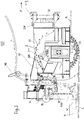
- FIG. 1 the new laying device according to the invention in plan view
- Fig. 2 the same in side view from the street that Fig. 3 this facility in side view from the outside towards the street
- Fig. 4 in rear view
- Fig. 5 and 6 explain the second subject matter of the invention from which the present invention is based.
- the Fig. 1 shows how a carrier or support frame 20 with a side extension device 2 is attached to the rear of a towing vehicle 1, for example a tractor, which is only indicated schematically as such and travels in the direction of travel F and remains strictly on the road surface Fb, which, as indicated by a double arrow, in linearly movable in both directions.
- a towing vehicle for example a tractor
- An articulation formed with the first swivel joint 230 with an essentially vertical axis is supported by two projections, which protrude from the extension device 2 and are spaced apart from one another, of which only the upper one is visible here, around which the tapered milling unit 3 with its housing 31 and the tapered milling wheel 35 can be pivoted sideways at an angle to the right or left, as is indicated by the curved double arrow.
- the side pivoting angle can be adjusted depending on the course of the curve.
- rollers 43 arranged inside the drag formwork and cable insertion unit 4 for kink-free guidance of the one to be installed are not clearly visible here shown, cable L from above the units 3 and 4 down into the cable truss K. which has just been created by the cable laying device 100 or its milling unit 3 and is recessed in the banquet B
- the drag formwork and cable insertion unit 4 can be lowered with respect to the milling unit 3 by means of the two parallelogram mechanisms 400 and is supported on the base of the collar, as a result of which the milling unit 3 is raised.
- the two material flows Kmf and Kmg arrive on two discharge chutes 62, 63, the fine and ultra-fine material Kmf reaching the coarse material Kg locally and temporally before the coarse material Kmg and embedding and embedding the cable inserted there and only then The K is finally filled with coarse material Kmg, which may also contain excess fine material Kmf.
- the Fig. 2 shows - with otherwise the same reference numerals - based on the direction of travel F of the overall laying unit 10 in a view from the right, clearly the milling wheel 35 with the carbide burrs and the ejection recess 36 in the housing 31 of the milling unit 3, through which the entire excavated material Km on the first conveyor belt 50 arrives and then rises from there to the star screen 55 with the plurality of rotating screen stars 51.
- a second conveyor belt 56 runs parallel to the same.
- the cable L is fed, which is guided downwards via cable rollers 75 and ultimately reaches the truss K via guide rollers (not visible here) within the drag formwork unit 4.
- the hydraulic cylinder 405 of the parallelogram mechanism 400 for lowering the drag formwork unit 4 which can serve, for example, to raise the milling unit 3 in the event of a blockage thereof.
- FIG. 3 The side view of the new, compact, movable cable laying compact unit 10 shown from the left clearly shows the mechanics 300 with hydraulic cylinder 305 for the depth adjustment of the milling wheel 35 relative to the milling unit 3, while the meanings of the reference symbols remain the same.
- the parallelogram mechanism 400 with hydraulic cylinder 405 for the relative height adjustment of milling unit 3 and drag formwork unit 4 to one another is shown very clearly.
- the unwinding drum 80 and the warning tape guide channel 81 for depositing the cable warning tape W above the cable L already stored in the knee K are also shown there.
- the Fig. 4 shows - with otherwise constant reference sign interpretations - on both sides of milling unit 3 and drag formwork and cable laying unit 4 the parallelogram mechanism 400 for the mutual relative raising or lowering of these two units 3 and 4 and their hydraulic cylinders 405 and it also shows that above and above Cable 75 on the upper side guided cable L, which is guided downwards by the unit 4 and placed between the two formwork sheets 41 on the bottom of the knee K.
- the two rails of the support frame 20 for the side extension unit 2 can be clearly seen here, as well as the actual edge of the carriageway Fb which is absolutely not to be touched or touched by the new cable laying compact unit 10 and is not at all damaged, i.e. e.g. Asphalt surface of the street along which the cable L is laid in the knee K produced in the banquet B.
- Each of the units 3 and 4 used directly during the excavation and cable laying is equipped on the underside with a drag bar 150, which ensures that the above-mentioned units stand securely on the banquet B during the cable laying journey.
- the milling unit 3 is connected to the milling wheel housing 31 with the carrier frame 20 on the carrier or front vehicle 1 via a standardized three-point suspension. All control and drive elements, not shown, are located on the support frame 20.
- the side extension unit 2 is integrated in the support 20 in the form of a tube in a tube system, which is mounted on rollers.
- the extension device 2 can be continuously extended and retracted laterally by means of hydraulic cylinders. By extending the same sideways, it is possible that the milling unit 3 is pulled laterally behind the carrier or front vehicle 1, and thus the milling of the knee K exactly and without any impairment or damage to the road surface Fb or the like in the side street strip or - banquet B can take place, and thus the road body itself is not touched by the construction work while the carrier or front vehicle 1 is moving safely on the fixed road body in the direction of travel F.
- the milling unit 3 or the milling housing 31 is connected to the side extension device 2, 20 via the first swivel joint 230.
- a controllable hydraulic cylinder which is connected to the extension device 2 and the milling housing 31, stabilizes the same.
- the rotary joint 230 makes it possible to mill tight curves, since the milling housing 31 is pressed into the curve radius required by the hydraulic cylinder 23 of the extension device 2, 20.
- a drive motor which is fastened to the milling housing 31, drives the milling wheel 35 axially. The milling wheel 35 is driven in the opposite direction to the direction of travel F, see arrow D there.
- Unit 4 fulfills three tasks:
- the drag formwork unit 4 is located or begins as directly as possible behind the milling wheel 35 and its concavely curved front surface is formed towards the same with a somewhat larger radius than the milling wheel 35 itself. This form of the drag formwork unit 4 prevents the milled material on the back from ultimately being able to be brought back into the collar K.
- Two side steel sheets 41 prevent the collapse of the knee K or the trickling of undesirable banquet substrate or kuenette material Km.
- the height-adjustable device 80, 81 on the rear side of the drag formwork unit 4 serves as a guide for depositing the warning tape W at the desired height above the laid cable L within the collar K.
- the drag formwork unit 4 is connected via the parallelogram mechanism 400 to the second swivel joint 340, which is fastened to the cutter housing 31.
- the swivel joint 340 enables the drag formwork unit 4 to be guided flexibly in the crank K in curves.
- the two lower supports of the parallelogram mechanism 400 are provided with an elongated hole in which the ends of two hydraulic cylinders are fastened by means of a bolt. The other end of the hydraulic cylinders is attached to the swivel 340 on the right and left.
- Hydraulic cylinders 405 make it possible to raise or lower the drag formwork unit 4 continuously.
- the milling wheel 35 comes to a standstill, for example due to impurities in the banquet base, it can be raised by means of the depth adjustment mechanism 300 for a new start.
- Elongated holes on the lower supports of the parallelogram mechanism 400 on both sides enable the milling housing 3 to be lifted relatively without the Drag formwork unit 4 itself is lifted upwards. This effectively prevents damage to the installed lines L and the collapse of the knee K.
- the rising conveyor belt 50 connects, which conveys the milled collar material Km in the direction of the drag formwork unit 4.
- the screening device begins, which is particularly preferably formed by an elongated, further increasing star screen 55.
- the star screen 55 separates the Rienettenmaterial km supplied to it in fine and coarse fractions Kmf and Kmg.
- the fines fall onto a conveyor belt 56 arranged below the same and are transported further to the rear into a swiveling discharge chute.
- the coarse material Kmg is also conveyed backwards into the discharge chute 63 during the screening process by the rotation of the screen stars 51.
- This swiveling discharge chute 63 which is located at the end of the above-mentioned sieve device, enables the milled-out channel material to be placed flexibly.
- the discharge chute can be swiveled in the direction of the truss K or in the direction of the carriageway. That side of the discharge chute 63, which is inclined in the direction of the bezel K, is divided into two channels.
- the screened fine material Kmf is deposited in a first channel in the direction of travel, the coarse material Kmg in the second channel.
- a height-adjustable deflector plate at the end of the first channel enables the fine material Kmf to be metered in via a cavity in the drag formwork unit 4 into the knee K.
- Excess fine material Kmf is passed through the deflector plate into the second channel and mixes there with the coarse material Kmg. With this grain mixture produced in the manner described, the knee K is ultimately closed.
- the carrier or front vehicle 1 which are preferably equipped with a stepless travel drive are.
- a device which can accommodate the cable drums.
- the cables or lines L to be installed are guided into the drag formwork and cable insertion unit 4 via guide rollers above the compact cable laying unit and from there inserted into the truss K.
- the combination of the described units 1, 2, 3, 4 ensures with high certainty that lines and / or cables L can be laid in the traffic lane border strip or banquet B without the roadway Fb of a street being damaged in the process. This is particularly true in the curve areas of streets and their banquets.
- FIG. 5 shows how a first vehicle 100, formed by a specially equipped tractor 100 and moving forward at a speed v1 in the range of 0 to about 4 km / h, carries a roll-off bearing fork 38 with a cable drum 30 mounted on it.
- the cable 3 to be laid underground is drawn off via a roller 31, which is arranged above the driver's cab, is guided downwards via a further roller 32 arranged at the rear, behind the tractor 100, and in which directly beforehand by means of the rear area of the tractor 100 arranged milling machine 40 freshly excavated cable trays 70 stored.
- a discharge chute 50 which is also arranged on the rear of the tractor 100, continuously allows cable (fine) sand 6 to flow into the cradle 70 in a predetermined amount per running meter of laying distance, by means of which the cable 3 and the cable above it stored warning tape 35 is encased and embedded and of course also covered upwards.
- the ground material 7 which is opposite in the course of the milling of the cable truss 70 by means of the trencher 40 and the conveyor belt 45 which is associated to the side thereof with the forward driving speed v1 of the tractor 100 minus v1 (-v1) and which is just not deposited to the side of the truss 70 is - immediately after the embedding and bedding of cable 3 and warning belt 35 with the cable (fine) sand 6 - via the discharge chute 41 of the conveyor belt 45 conveying backwards back into the cradle 70.
- a second vehicle 200 im which is moving forward at the same speed v1
- the amount of cable (fine) sand provided per running meter of travel and thus cable-laying section, which is to be introduced into the cable tray 70, is applied to the conveyor belt 240 in the rear area of the dump truck 200 by means of the sand outlet and metering device 205, which can be regulated from the driver's cab.
- Both the tractor 100 and the trough truck 200 following it at a distance a with synchronous speed v2 v1 move forward in the course of the novel cable laying at a speed of 0 to about 4 km / h.
- both vehicles 100, 200 are equipped with computer-controlled hydraulic or hydrostatic transmissions.
- a sand conveyor hose can occur, the open end of which is guided directly above the cable trough 70 and through which the cable sand 6 can be conveyed compressed air directly into the trough 70.
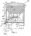
- the trough truck 200 forming the second vehicle and shown in rear and sectional view can be a conventional, for example multi-axle, transport vehicle for dry, fine-grained or powdery material, mostly building material, with a transport trough 12 be at an angle ⁇ downwards toward each other towards flanks 11, on the, for example 60 cm narrow, base of which a scraper belt 13 is moved, which can be regulated by means of motor 131, the speed of which is adjustable by means of the control unit which can be adjusted and regulated from the cab of the second vehicle 200 is drivable, by means of which the amount of cable (fine) sand 6 to be deployed in each running meter is directed onto a conveyor trough 16 with a discharge screw 17 oriented transversely to the vehicle axis or to the direction of travel of the dump truck 200, which, for example, is on the left side of the dump truck 200 protrudes with a protrusion.
- a transport trough 12 be at an angle ⁇ downwards toward each other towards flanks 11, on the
- the (fine) sand 6 conveyed by means of the discharge screw 17 is conveyed through a kind of funnel member 204 or such a hose of the sand discharge and metering device 205 onto a conveyor belt 240 which is attached to the side of the vehicle 200 and rises upwards with its front discharge end 245 via the only
- the sand discharge chute 50 of the first vehicle 100 drawn with broken lines, transports and falls through it exactly positioned directly into the cable cage 70 already occupied by the cable 3.
Priority Applications (4)
| Application Number | Priority Date | Filing Date | Title |
|---|---|---|---|
| PL19190076T PL3587672T3 (pl) | 2016-09-08 | 2017-08-18 | Urządzenie do oraz sposób układania kabli |
| SI201730897T SI3587672T1 (sl) | 2016-09-08 | 2017-08-18 | Priprava in postopek za polaganje kablov |
| RS20211053A RS62367B1 (sr) | 2016-09-08 | 2017-08-18 | Uređaj i postupak za polaganje kablova |
| HRP20211420TT HRP20211420T1 (hr) | 2016-09-08 | 2017-08-18 | Uređaj i postupak za rukovanje kabelom |
Applications Claiming Priority (3)
| Application Number | Priority Date | Filing Date | Title |
|---|---|---|---|
| ATA50797/2016A AT519075B1 (de) | 2016-09-08 | 2016-09-08 | Verfahren und Vorrichtung zum Verlegen von Kabeln und/oder dgl. |
| EP17764317.8A EP3426850B1 (fr) | 2016-09-08 | 2017-08-18 | Dispostif de pose de câbles |
| PCT/AT2017/060205 WO2018045404A1 (fr) | 2016-09-08 | 2017-08-18 | Dispositif et procédé de pose de câbles |
Related Parent Applications (2)
| Application Number | Title | Priority Date | Filing Date |
|---|---|---|---|
| EP17764317.8A Division EP3426850B1 (fr) | 2016-09-08 | 2017-08-18 | Dispostif de pose de câbles |
| EP17764317.8A Division-Into EP3426850B1 (fr) | 2016-09-08 | 2017-08-18 | Dispostif de pose de câbles |
Publications (3)
| Publication Number | Publication Date |
|---|---|
| EP3587672A2 true EP3587672A2 (fr) | 2020-01-01 |
| EP3587672A3 EP3587672A3 (fr) | 2020-05-06 |
| EP3587672B1 EP3587672B1 (fr) | 2021-07-28 |
Family
ID=59811028
Family Applications (4)
| Application Number | Title | Priority Date | Filing Date |
|---|---|---|---|
| EP19190076.0A Active EP3587672B1 (fr) | 2016-09-08 | 2017-08-18 | Dispositif et procédé de pose de câble |
| EP19154966.6A Active EP3495566B1 (fr) | 2016-09-08 | 2017-08-18 | Dispositif et procédé de pose de câblé |
| EP17764317.8A Active EP3426850B1 (fr) | 2016-09-08 | 2017-08-18 | Dispostif de pose de câbles |
| EP19198557.1A Active EP3623533B1 (fr) | 2016-09-08 | 2017-08-18 | Dispositif et procédé de pose de câble |
Family Applications After (3)
| Application Number | Title | Priority Date | Filing Date |
|---|---|---|---|
| EP19154966.6A Active EP3495566B1 (fr) | 2016-09-08 | 2017-08-18 | Dispositif et procédé de pose de câblé |
| EP17764317.8A Active EP3426850B1 (fr) | 2016-09-08 | 2017-08-18 | Dispostif de pose de câbles |
| EP19198557.1A Active EP3623533B1 (fr) | 2016-09-08 | 2017-08-18 | Dispositif et procédé de pose de câble |
Country Status (20)
| Country | Link |
|---|---|
| US (2) | US10465360B2 (fr) |
| EP (4) | EP3587672B1 (fr) |
| AT (2) | AT519075B1 (fr) |
| AU (1) | AU2017322766B2 (fr) |
| BR (1) | BR112020002509A2 (fr) |
| CA (1) | CA3036268A1 (fr) |
| CY (2) | CY1122599T1 (fr) |
| DE (1) | DE202017006995U1 (fr) |
| DK (3) | DK3426850T3 (fr) |
| ES (4) | ES2934809T3 (fr) |
| FI (1) | FI3495566T3 (fr) |
| HR (4) | HRP20221156T1 (fr) |
| HU (4) | HUE060622T2 (fr) |
| LT (4) | LT3623533T (fr) |
| PL (4) | PL3426850T3 (fr) |
| PT (4) | PT3426850T (fr) |
| RS (4) | RS62367B1 (fr) |
| RU (1) | RU2747769C1 (fr) |
| SI (3) | SI3495566T1 (fr) |
| WO (1) | WO2018045404A1 (fr) |
Families Citing this family (8)
| Publication number | Priority date | Publication date | Assignee | Title |
|---|---|---|---|---|
| EP3887698A4 (fr) * | 2018-11-30 | 2022-08-17 | Corning Research & Development Corporation | Éléments de chaussée broyés pour chemins de câbles et de bandes |
| DE202018107405U1 (de) * | 2018-12-21 | 2019-01-23 | Jürgen Stehr | Vorrichtung zum Verlegen von Kabeln und/oder Leitungen |
| CN109713614B (zh) * | 2019-02-26 | 2020-08-18 | 南京飞阳输变电工程有限公司 | 多功能电缆敷设车架 |
| CN111549841B (zh) * | 2020-06-10 | 2021-07-27 | 广州市思童电子科技有限公司 | 一种地下电缆挖沟铺设机 |
| US11619019B2 (en) * | 2021-04-06 | 2023-04-04 | Saudi Arabian Oil Company | Automated system and installation process for a flexible mat fabric |
| CN113572080B (zh) * | 2021-06-18 | 2022-10-18 | 北京万兴建筑集团有限公司 | 一种建筑工程大直径电缆敷设的施工装置及施工方法 |
| CN116575528B (zh) * | 2023-05-15 | 2024-01-09 | 浙江尚瓯电力工程建设有限公司 | 一种直埋电缆沟的开挖装置 |
| CN116979453B (zh) * | 2023-09-22 | 2024-02-27 | 福建国威电子科技股份有限公司 | 车载主动防护系统电缆组件及制备方法 |
Citations (13)
| Publication number | Priority date | Publication date | Assignee | Title |
|---|---|---|---|---|
| GB410900A (en) | 1932-12-23 | 1934-05-31 | County Of London Electric Supp | Improvements in or relating to apparatus for laying underground cables |
| US3203188A (en) | 1961-10-23 | 1965-08-31 | Jetco Inc | Method and apparatus for preparing a trench for a subsurface conduit line and for laying such a line |
| US3332249A (en) | 1965-01-22 | 1967-07-25 | Challenge Cook Bros Inc | Trench digging and refilling apparatus |
| DE2504598A1 (de) | 1975-02-04 | 1976-08-05 | Heinrich Kortt | Kabel-rohrschnellverlegungskonstruktion ohne aushub |
| JPS5829924A (ja) | 1981-08-11 | 1983-02-22 | Seirei Ind Co Ltd | ガス管埋設機における自動往復行装置 |
| US4812078A (en) | 1986-06-26 | 1989-03-14 | Ets. Rivard S.A. | Mechanized unit for digging a trench and laying elongate objects |
| US4871281A (en) | 1988-02-28 | 1989-10-03 | Justice Donald R | Trenching tool for installing perforated pipe |
| US5743675A (en) | 1994-08-03 | 1998-04-28 | Mears/Cpg, Inc. | Underground cable anode installment system |
| US6189244B1 (en) | 1999-09-15 | 2001-02-20 | Randal Johnson | Self-cleaning narrow ditch trencher and flexible tile installer |
| US6457267B1 (en) | 2000-02-02 | 2002-10-01 | Roger D. Porter | Trenching and edging system |
| US20100104374A1 (en) | 2008-10-24 | 2010-04-29 | Ronald Hall | Conduit Laying Machine |
| US20150252551A1 (en) | 2014-03-06 | 2015-09-10 | Quanta Associates, Lp | Automated below ground cable installation within a select fill |
| DE102014105577A1 (de) | 2014-04-17 | 2015-10-22 | Novoter Ag | Vorrichtung und Verfahren sowie Verlegeanlage zum Verlegen mindestens eines Stranges in einer Bodenfläche |
Family Cites Families (11)
| Publication number | Priority date | Publication date | Assignee | Title |
|---|---|---|---|---|
| SU909040A1 (ru) * | 1980-07-18 | 1982-02-28 | Государственное Специально-Конструкторское Бюро По Механизации Ирригационно-Мелиоративных Работ И Поливов Хлопчатника | Устройство дл укладки дренажных труб |
| US5070632A (en) * | 1991-05-08 | 1991-12-10 | Trencor Jetco, Inc. | Trenching machine with laterally adjustable chain-type digging implement |
| US5271168A (en) * | 1992-07-17 | 1993-12-21 | Wilson Sr Gilbert T | Pipeline padding machine |
| FR2695148B1 (fr) * | 1992-08-25 | 1994-11-18 | Equip Electricite Entreprise | Procédé et dispositif dans le cadre de la pose mécanisée de canalisations électriques souterraines ou de tout autre canalisation de souplesse équivalente comportant une protection mécanique par mortier ou sable par exemple. |
| US5573347A (en) * | 1994-05-31 | 1996-11-12 | Miles; Robert K. | Drain preparation apparatus and method of using same |
| FR2722809B1 (fr) * | 1994-07-20 | 1996-09-20 | Marais Sa | Vehicule pour recouvrir des objets allonges a enfouir |
| US5575538A (en) * | 1995-06-01 | 1996-11-19 | Astec Industries, Inc. | Rock saw with centerline conveyor assembly and method of digging a narrow trench |
| RU2274707C1 (ru) * | 2004-12-08 | 2006-04-20 | Государственное научное учреждение Всероссийский научно-исследовательский институт гидротехники и мелиорации им. А.Н. Костякова | Способ строительства дренажа в водонасыщенных грунтах и устройство для его осуществления |
| FR2944300B1 (fr) | 2009-04-10 | 2011-06-10 | Marais Contracting Services | Engin motorise pour creuser une tranchee dans le sol et poser, dans celle-ci, des objets allonges |
| US8596914B2 (en) * | 2010-10-21 | 2013-12-03 | Thomas Jeffrey Baber | Tile laying and covering apparatus |
| DE102015010011B4 (de) * | 2015-08-05 | 2020-03-19 | Wirtgen Gmbh | Selbstfahrende Baumaschine und Verfahren zur Anzeige der Umgebung einer selbstfahrenden Baumaschine |
-
2016
- 2016-09-08 AT ATA50797/2016A patent/AT519075B1/de active
-
2017
- 2017-08-18 DK DK17764317.8T patent/DK3426850T3/da active
- 2017-08-18 EP EP19190076.0A patent/EP3587672B1/fr active Active
- 2017-08-18 LT LTEP19198557.1T patent/LT3623533T/lt unknown
- 2017-08-18 HU HUE19154966A patent/HUE060622T2/hu unknown
- 2017-08-18 LT LTEP19154966.6T patent/LT3495566T/lt unknown
- 2017-08-18 EP EP19154966.6A patent/EP3495566B1/fr active Active
- 2017-08-18 BR BR112020002509-7A patent/BR112020002509A2/pt unknown
- 2017-08-18 AT ATGM50018/2019U patent/AT16387U3/de unknown
- 2017-08-18 PT PT177643178T patent/PT3426850T/pt unknown
- 2017-08-18 HU HUE19190076A patent/HUE056304T2/hu unknown
- 2017-08-18 DK DK19190076.0T patent/DK3587672T3/da active
- 2017-08-18 ES ES19154966T patent/ES2934809T3/es active Active
- 2017-08-18 PT PT191985571T patent/PT3623533T/pt unknown
- 2017-08-18 DE DE202017006995.4U patent/DE202017006995U1/de active Active
- 2017-08-18 RU RU2020107489A patent/RU2747769C1/ru active
- 2017-08-18 HR HRP20221156TT patent/HRP20221156T1/hr unknown
- 2017-08-18 SI SI201731277T patent/SI3495566T1/sl unknown
- 2017-08-18 PT PT191900760T patent/PT3587672T/pt unknown
- 2017-08-18 RS RS20211053A patent/RS62367B1/sr unknown
- 2017-08-18 ES ES19198557T patent/ES2927765T3/es active Active
- 2017-08-18 DK DK19198557.1T patent/DK3623533T3/da active
- 2017-08-18 PL PL17764317T patent/PL3426850T3/pl unknown
- 2017-08-18 US US16/331,548 patent/US10465360B2/en active Active
- 2017-08-18 CA CA3036268A patent/CA3036268A1/fr active Pending
- 2017-08-18 HU HUE17764317A patent/HUE047745T2/hu unknown
- 2017-08-18 PL PL19154966.6T patent/PL3495566T3/pl unknown
- 2017-08-18 RS RS20220832A patent/RS63614B1/sr unknown
- 2017-08-18 HR HRP20211420TT patent/HRP20211420T1/hr unknown
- 2017-08-18 EP EP17764317.8A patent/EP3426850B1/fr active Active
- 2017-08-18 EP EP19198557.1A patent/EP3623533B1/fr active Active
- 2017-08-18 WO PCT/AT2017/060205 patent/WO2018045404A1/fr active Application Filing
- 2017-08-18 SI SI201730144T patent/SI3426850T1/sl unknown
- 2017-08-18 AU AU2017322766A patent/AU2017322766B2/en active Active
- 2017-08-18 LT LTEP17764317.8T patent/LT3426850T/lt unknown
- 2017-08-18 ES ES17764317T patent/ES2764429T3/es active Active
- 2017-08-18 PL PL19198557.1T patent/PL3623533T3/pl unknown
- 2017-08-18 HR HRP20221503TT patent/HRP20221503T1/hr unknown
- 2017-08-18 RS RS20221123A patent/RS63824B1/sr unknown
- 2017-08-18 PL PL19190076T patent/PL3587672T3/pl unknown
- 2017-08-18 SI SI201730897T patent/SI3587672T1/sl unknown
- 2017-08-18 ES ES19190076T patent/ES2889248T3/es active Active
- 2017-08-18 PT PT191549666T patent/PT3495566T/pt unknown
- 2017-08-18 LT LTEP19190076.0T patent/LT3587672T/lt unknown
- 2017-08-18 RS RS20191666A patent/RS59794B1/sr unknown
- 2017-08-18 FI FIEP19154966.6T patent/FI3495566T3/de active
- 2017-08-18 HU HUE19198557A patent/HUE059956T2/hu unknown
-
2019
- 2019-09-24 US US16/579,907 patent/US11060259B2/en active Active
- 2019-12-18 CY CY20191101330T patent/CY1122599T1/el unknown
- 2019-12-20 HR HRP20192310TT patent/HRP20192310T1/hr unknown
-
2021
- 2021-09-09 CY CY20211100796T patent/CY1124649T1/el unknown
Patent Citations (13)
| Publication number | Priority date | Publication date | Assignee | Title |
|---|---|---|---|---|
| GB410900A (en) | 1932-12-23 | 1934-05-31 | County Of London Electric Supp | Improvements in or relating to apparatus for laying underground cables |
| US3203188A (en) | 1961-10-23 | 1965-08-31 | Jetco Inc | Method and apparatus for preparing a trench for a subsurface conduit line and for laying such a line |
| US3332249A (en) | 1965-01-22 | 1967-07-25 | Challenge Cook Bros Inc | Trench digging and refilling apparatus |
| DE2504598A1 (de) | 1975-02-04 | 1976-08-05 | Heinrich Kortt | Kabel-rohrschnellverlegungskonstruktion ohne aushub |
| JPS5829924A (ja) | 1981-08-11 | 1983-02-22 | Seirei Ind Co Ltd | ガス管埋設機における自動往復行装置 |
| US4812078A (en) | 1986-06-26 | 1989-03-14 | Ets. Rivard S.A. | Mechanized unit for digging a trench and laying elongate objects |
| US4871281A (en) | 1988-02-28 | 1989-10-03 | Justice Donald R | Trenching tool for installing perforated pipe |
| US5743675A (en) | 1994-08-03 | 1998-04-28 | Mears/Cpg, Inc. | Underground cable anode installment system |
| US6189244B1 (en) | 1999-09-15 | 2001-02-20 | Randal Johnson | Self-cleaning narrow ditch trencher and flexible tile installer |
| US6457267B1 (en) | 2000-02-02 | 2002-10-01 | Roger D. Porter | Trenching and edging system |
| US20100104374A1 (en) | 2008-10-24 | 2010-04-29 | Ronald Hall | Conduit Laying Machine |
| US20150252551A1 (en) | 2014-03-06 | 2015-09-10 | Quanta Associates, Lp | Automated below ground cable installation within a select fill |
| DE102014105577A1 (de) | 2014-04-17 | 2015-10-22 | Novoter Ag | Vorrichtung und Verfahren sowie Verlegeanlage zum Verlegen mindestens eines Stranges in einer Bodenfläche |
Also Published As
Similar Documents
| Publication | Publication Date | Title |
|---|---|---|
| EP3623533B1 (fr) | Dispositif et procédé de pose de câble | |
| EP1964973B1 (fr) | Procédé destiné à la fabrication d'un canal d'alimentation et train constitués de véhicules destinés à l'exécution du procédé | |
| EP0255564B1 (fr) | Machine pour remplacer ou rénover respectivement les rails et les traverses d'une voie existante | |
| EP0670932B1 (fr) | Machine de pose de voie pour le renouvellement des voies ferrees | |
| DE2548338C3 (de) | Verfahren zur Aufnahme von Schnee und gezielten Verteilung desselben auf einer Skipiste sowie Vorrichtung zur Durchführung des Verfahrens | |
| DE4205557A1 (de) | Mobile verbindungsbandbruecke fuer den tagebau | |
| EP0771909B1 (fr) | Machine pour le démontage d'une ancienne voie ferrée et l'installation d'une nouvelle voie | |
| DE102017004302B3 (de) | Kabelverlegemaschine | |
| EP2213792A2 (fr) | Procédé de pose d'éléments de canaux en forme de U à côté du rail d'une voie ferrée | |
| DE3607245C2 (de) | Verfahren zum Herstellen eines Schotterbettes, insbesondere für Eisenbahngleise auf einem Planum sowie Schotter-Band-Fertiger zur Durchführung des Verfahrens | |
| DE102011051554B4 (de) | Grabenfräse | |
| DE19839744A1 (de) | Verfahren zum Bewegen einer zwischen Tagebaugeräten angeordneten Verbindungsbandbrücke sowie mobile Verbindungsbandbrücke für den Tagebau | |
| DE102018000553B4 (de) | Leerrohr- Verlegemaschine für Kabeltrassen mit Flüssigbodenerzeugung | |
| DE584769C (de) | Absetzer mit zum Aufnehmen, Foerdern und freien Austragen des Gutes dienender Eimerkette | |
| DE4106729A1 (de) | Verfahren und geraet zum aufbringen einer trag- oder verschleissschicht aus schotter oder dergleichen material auf wege | |
| DE202007017037U1 (de) | Vorrichtung zum Ausbauen und Verladen von Gleisschotter | |
| DE2636342A1 (de) | Vorrichtung zum fortlaufenden auffuellen von graeben, aushebungen u.dgl. mit material | |
| DE102008003951A1 (de) | Vorrichtung zum Verbringen von Baustoffen für einen Unterbau und/oder Oberbau einer Fahrbahn | |
| DE6809232U (de) | Vorrichtung zum verlegen und anzeigen von leitungen im erdboden | |
| DD209006A5 (de) | Gleisbauzug zur erneuerung von eisenbahngleisen | |
| WO2004094729A1 (fr) | Procede de production de couches de pierres concassees | |
| EP0786558A1 (fr) | Appareillage mobile le reconditionnement de déblais d'une voie ferrée |
Legal Events
| Date | Code | Title | Description |
|---|---|---|---|
| PUAI | Public reference made under article 153(3) epc to a published international application that has entered the european phase |
Free format text: ORIGINAL CODE: 0009012 |
|
| STAA | Information on the status of an ep patent application or granted ep patent |
Free format text: STATUS: THE APPLICATION HAS BEEN PUBLISHED |
|
| AC | Divisional application: reference to earlier application |
Ref document number: 3426850 Country of ref document: EP Kind code of ref document: P |
|
| AK | Designated contracting states |
Kind code of ref document: A2 Designated state(s): AL AT BE BG CH CY CZ DE DK EE ES FI FR GB GR HR HU IE IS IT LI LT LU LV MC MK MT NL NO PL PT RO RS SE SI SK SM TR |
|
| RIC1 | Information provided on ipc code assigned before grant |
Ipc: E02F 5/08 20060101ALI20191217BHEP Ipc: E02F 5/12 20060101ALI20191217BHEP Ipc: E02F 5/10 20060101AFI20191217BHEP Ipc: E02F 5/14 20060101ALI20191217BHEP |
|
| PUAL | Search report despatched |
Free format text: ORIGINAL CODE: 0009013 |
|
| AK | Designated contracting states |
Kind code of ref document: A3 Designated state(s): AL AT BE BG CH CY CZ DE DK EE ES FI FR GB GR HR HU IE IS IT LI LT LU LV MC MK MT NL NO PL PT RO RS SE SI SK SM TR |
|
| RIC1 | Information provided on ipc code assigned before grant |
Ipc: E02F 5/10 20060101AFI20200330BHEP Ipc: E02F 5/12 20060101ALI20200330BHEP Ipc: E02F 5/14 20060101ALI20200330BHEP Ipc: E02F 5/08 20060101ALI20200330BHEP |
|
| STAA | Information on the status of an ep patent application or granted ep patent |
Free format text: STATUS: REQUEST FOR EXAMINATION WAS MADE |
|
| 17P | Request for examination filed |
Effective date: 20201105 |
|
| RBV | Designated contracting states (corrected) |
Designated state(s): AL AT BE BG CH CY CZ DE DK EE ES FI FR GB GR HR HU IE IS IT LI LT LU LV MC MK MT NL NO PL PT RO RS SE SI SK SM TR |
|
| GRAP | Despatch of communication of intention to grant a patent |
Free format text: ORIGINAL CODE: EPIDOSNIGR1 |
|
| STAA | Information on the status of an ep patent application or granted ep patent |
Free format text: STATUS: GRANT OF PATENT IS INTENDED |
|
| INTG | Intention to grant announced |
Effective date: 20210412 |
|
| GRAS | Grant fee paid |
Free format text: ORIGINAL CODE: EPIDOSNIGR3 |
|
| GRAA | (expected) grant |
Free format text: ORIGINAL CODE: 0009210 |
|
| STAA | Information on the status of an ep patent application or granted ep patent |
Free format text: STATUS: THE PATENT HAS BEEN GRANTED |
|
| AC | Divisional application: reference to earlier application |
Ref document number: 3426850 Country of ref document: EP Kind code of ref document: P |
|
| AK | Designated contracting states |
Kind code of ref document: B1 Designated state(s): AL AT BE BG CH CY CZ DE DK EE ES FI FR GB GR HR HU IE IS IT LI LT LU LV MC MK MT NL NO PL PT RO RS SE SI SK SM TR |
|
| REG | Reference to a national code |
Ref country code: GB Ref legal event code: FG4D Free format text: NOT ENGLISH |
|
| REG | Reference to a national code |
Ref country code: CH Ref legal event code: EP |
|
| REG | Reference to a national code |
Ref country code: AT Ref legal event code: REF Ref document number: 1414848 Country of ref document: AT Kind code of ref document: T Effective date: 20210815 |
|
| REG | Reference to a national code |
Ref country code: IE Ref legal event code: FG4D Free format text: LANGUAGE OF EP DOCUMENT: GERMAN |
|
| REG | Reference to a national code |
Ref country code: DE Ref legal event code: R096 Ref document number: 502017011065 Country of ref document: DE |
|
| REG | Reference to a national code |
Ref country code: RO Ref legal event code: EPE Ref country code: HR Ref legal event code: TUEP Ref document number: P20211420T Country of ref document: HR |
|
| REG | Reference to a national code |
Ref country code: FI Ref legal event code: FGE |
|
| REG | Reference to a national code |
Ref country code: PT Ref legal event code: SC4A Ref document number: 3587672 Country of ref document: PT Date of ref document: 20210916 Kind code of ref document: T Free format text: AVAILABILITY OF NATIONAL TRANSLATION Effective date: 20210910 |
|
| REG | Reference to a national code |
Ref country code: DK Ref legal event code: T3 Effective date: 20210914 |
|
| REG | Reference to a national code |
Ref country code: NL Ref legal event code: FP |
|
| REG | Reference to a national code |
Ref country code: SE Ref legal event code: TRGR |
|
| REG | Reference to a national code |
Ref country code: GR Ref legal event code: EP Ref document number: 20210402490 Country of ref document: GR Effective date: 20211013 |
|
| REG | Reference to a national code |
Ref country code: EE Ref legal event code: FG4A Ref document number: E021416 Country of ref document: EE Effective date: 20210913 |
|
| REG | Reference to a national code |
Ref country code: NO Ref legal event code: T2 Effective date: 20210728 |
|
| REG | Reference to a national code |
Ref country code: HR Ref legal event code: ODRP Ref document number: P20211420T Country of ref document: HR Payment date: 20210910 Year of fee payment: 5 |
|
| REG | Reference to a national code |
Ref country code: ES Ref legal event code: FG2A Ref document number: 2889248 Country of ref document: ES Kind code of ref document: T3 Effective date: 20220111 |
|
| REG | Reference to a national code |
Ref country code: SK Ref legal event code: T3 Ref document number: E 38510 Country of ref document: SK |
|
| REG | Reference to a national code |
Ref country code: HR Ref legal event code: T1PR Ref document number: P20211420 Country of ref document: HR |
|
| REG | Reference to a national code |
Ref country code: HU Ref legal event code: AG4A Ref document number: E056304 Country of ref document: HU |
|
| REG | Reference to a national code |
Ref country code: DE Ref legal event code: R097 Ref document number: 502017011065 Country of ref document: DE |
|
| PLBE | No opposition filed within time limit |
Free format text: ORIGINAL CODE: 0009261 |
|
| STAA | Information on the status of an ep patent application or granted ep patent |
Free format text: STATUS: NO OPPOSITION FILED WITHIN TIME LIMIT |
|
| 26N | No opposition filed |
Effective date: 20220429 |
|
| REG | Reference to a national code |
Ref country code: HR Ref legal event code: ODRP Ref document number: P20211420 Country of ref document: HR Payment date: 20220809 Year of fee payment: 6 |
|
| P01 | Opt-out of the competence of the unified patent court (upc) registered |
Effective date: 20230621 |
|
| PGFP | Annual fee paid to national office [announced via postgrant information from national office to epo] |
Ref country code: IS Payment date: 20230626 Year of fee payment: 7 |
|
| REG | Reference to a national code |
Ref country code: HR Ref legal event code: ODRP Ref document number: P20211420 Country of ref document: HR Payment date: 20230814 Year of fee payment: 7 |
|
| PGFP | Annual fee paid to national office [announced via postgrant information from national office to epo] |
Ref country code: NL Payment date: 20230821 Year of fee payment: 7 Ref country code: LU Payment date: 20230821 Year of fee payment: 7 |
|
| PGFP | Annual fee paid to national office [announced via postgrant information from national office to epo] |
Ref country code: TR Payment date: 20230816 Year of fee payment: 7 Ref country code: SM Payment date: 20230726 Year of fee payment: 7 Ref country code: RO Payment date: 20230810 Year of fee payment: 7 Ref country code: NO Payment date: 20230824 Year of fee payment: 7 Ref country code: MC Payment date: 20230823 Year of fee payment: 7 Ref country code: IT Payment date: 20230825 Year of fee payment: 7 Ref country code: IE Payment date: 20230822 Year of fee payment: 7 Ref country code: GB Payment date: 20230822 Year of fee payment: 7 Ref country code: FI Payment date: 20230821 Year of fee payment: 7 Ref country code: EE Payment date: 20230814 Year of fee payment: 7 Ref country code: CZ Payment date: 20230815 Year of fee payment: 7 Ref country code: CY Payment date: 20230720 Year of fee payment: 7 Ref country code: CH Payment date: 20230902 Year of fee payment: 7 Ref country code: BG Payment date: 20230823 Year of fee payment: 7 Ref country code: AT Payment date: 20230807 Year of fee payment: 7 |
|
| PGFP | Annual fee paid to national office [announced via postgrant information from national office to epo] |
Ref country code: SK Payment date: 20230814 Year of fee payment: 7 Ref country code: SI Payment date: 20230810 Year of fee payment: 7 Ref country code: SE Payment date: 20230821 Year of fee payment: 7 Ref country code: RS Payment date: 20230810 Year of fee payment: 7 Ref country code: PT Payment date: 20230810 Year of fee payment: 7 Ref country code: PL Payment date: 20230811 Year of fee payment: 7 Ref country code: HU Payment date: 20230823 Year of fee payment: 7 Ref country code: HR Payment date: 20230814 Year of fee payment: 7 Ref country code: GR Payment date: 20230822 Year of fee payment: 7 Ref country code: FR Payment date: 20230828 Year of fee payment: 7 Ref country code: DK Payment date: 20230823 Year of fee payment: 7 Ref country code: DE Payment date: 20230821 Year of fee payment: 7 Ref country code: BE Payment date: 20230821 Year of fee payment: 7 |
|
| PGFP | Annual fee paid to national office [announced via postgrant information from national office to epo] |
Ref country code: MT Payment date: 20230721 Year of fee payment: 7 Ref country code: LV Payment date: 20230816 Year of fee payment: 7 Ref country code: LT Payment date: 20230721 Year of fee payment: 7 |
|
| PGFP | Annual fee paid to national office [announced via postgrant information from national office to epo] |
Ref country code: ES Payment date: 20231027 Year of fee payment: 7 |
|
| PGFP | Annual fee paid to national office [announced via postgrant information from national office to epo] |
Ref country code: AL Payment date: 20230822 Year of fee payment: 7 |
|
| PGFP | Annual fee paid to national office [announced via postgrant information from national office to epo] |
Ref country code: MK Payment date: 20230721 Year of fee payment: 7 |