EP3586974B1 - Pomme de douche sanitaire - Google Patents
Pomme de douche sanitaire Download PDFInfo
- Publication number
- EP3586974B1 EP3586974B1 EP19182263.4A EP19182263A EP3586974B1 EP 3586974 B1 EP3586974 B1 EP 3586974B1 EP 19182263 A EP19182263 A EP 19182263A EP 3586974 B1 EP3586974 B1 EP 3586974B1
- Authority
- EP
- European Patent Office
- Prior art keywords
- jet
- shower head
- disk
- contour
- fluid
- Prior art date
- Legal status (The legal status is an assumption and is not a legal conclusion. Google has not performed a legal analysis and makes no representation as to the accuracy of the status listed.)
- Active
Links
- 239000012530 fluid Substances 0.000 claims description 150
- 239000000463 material Substances 0.000 claims description 10
- 239000007921 spray Substances 0.000 description 19
- XLYOFNOQVPJJNP-UHFFFAOYSA-N water Substances O XLYOFNOQVPJJNP-UHFFFAOYSA-N 0.000 description 11
- 229920001971 elastomer Polymers 0.000 description 7
- 239000002184 metal Substances 0.000 description 5
- 230000001419 dependent effect Effects 0.000 description 4
- 239000000806 elastomer Substances 0.000 description 4
- 239000004033 plastic Substances 0.000 description 3
- 239000005060 rubber Substances 0.000 description 3
- 238000004140 cleaning Methods 0.000 description 2
- 230000009191 jumping Effects 0.000 description 2
- 238000004519 manufacturing process Methods 0.000 description 2
- 230000002093 peripheral effect Effects 0.000 description 2
- 235000008733 Citrus aurantifolia Nutrition 0.000 description 1
- 235000011941 Tilia x europaea Nutrition 0.000 description 1
- 230000007423 decrease Effects 0.000 description 1
- 230000005489 elastic deformation Effects 0.000 description 1
- 239000004571 lime Substances 0.000 description 1
- 239000012528 membrane Substances 0.000 description 1
- 238000000034 method Methods 0.000 description 1
- 239000000203 mixture Substances 0.000 description 1
- 238000003825 pressing Methods 0.000 description 1
- 239000007787 solid Substances 0.000 description 1
- 238000011144 upstream manufacturing Methods 0.000 description 1
Images

Classifications
-
- B—PERFORMING OPERATIONS; TRANSPORTING
- B05—SPRAYING OR ATOMISING IN GENERAL; APPLYING FLUENT MATERIALS TO SURFACES, IN GENERAL
- B05B—SPRAYING APPARATUS; ATOMISING APPARATUS; NOZZLES
- B05B15/00—Details of spraying plant or spraying apparatus not otherwise provided for; Accessories
- B05B15/50—Arrangements for cleaning; Arrangements for preventing deposits, drying-out or blockage; Arrangements for detecting improper discharge caused by the presence of foreign matter
- B05B15/52—Arrangements for cleaning; Arrangements for preventing deposits, drying-out or blockage; Arrangements for detecting improper discharge caused by the presence of foreign matter for removal of clogging particles
- B05B15/522—Arrangements for cleaning; Arrangements for preventing deposits, drying-out or blockage; Arrangements for detecting improper discharge caused by the presence of foreign matter for removal of clogging particles using cleaning elements penetrating the discharge openings
- B05B15/5223—Arrangements for cleaning; Arrangements for preventing deposits, drying-out or blockage; Arrangements for detecting improper discharge caused by the presence of foreign matter for removal of clogging particles using cleaning elements penetrating the discharge openings the cleaning element, e.g. a needle, and the discharge opening being movable relative to each other in a direction substantially parallel to the flow of liquid or other fluent material through said opening
- B05B15/5225—Arrangements for cleaning; Arrangements for preventing deposits, drying-out or blockage; Arrangements for detecting improper discharge caused by the presence of foreign matter for removal of clogging particles using cleaning elements penetrating the discharge openings the cleaning element, e.g. a needle, and the discharge opening being movable relative to each other in a direction substantially parallel to the flow of liquid or other fluent material through said opening the cleaning element being located upstream of the discharge opening or being actuated upstream therefrom
-
- B—PERFORMING OPERATIONS; TRANSPORTING
- B05—SPRAYING OR ATOMISING IN GENERAL; APPLYING FLUENT MATERIALS TO SURFACES, IN GENERAL
- B05B—SPRAYING APPARATUS; ATOMISING APPARATUS; NOZZLES
- B05B1/00—Nozzles, spray heads or other outlets, with or without auxiliary devices such as valves, heating means
- B05B1/14—Nozzles, spray heads or other outlets, with or without auxiliary devices such as valves, heating means with multiple outlet openings; with strainers in or outside the outlet opening
- B05B1/18—Roses; Shower heads
- B05B1/185—Roses; Shower heads characterised by their outlet element; Mounting arrangements therefor
-
- B—PERFORMING OPERATIONS; TRANSPORTING
- B05—SPRAYING OR ATOMISING IN GENERAL; APPLYING FLUENT MATERIALS TO SURFACES, IN GENERAL
- B05B—SPRAYING APPARATUS; ATOMISING APPARATUS; NOZZLES
- B05B1/00—Nozzles, spray heads or other outlets, with or without auxiliary devices such as valves, heating means
- B05B1/28—Nozzles, spray heads or other outlets, with or without auxiliary devices such as valves, heating means with integral means for shielding the discharged liquid or other fluent material, e.g. to limit area of spray; with integral means for catching drips or collecting surplus liquid or other fluent material
-
- B—PERFORMING OPERATIONS; TRANSPORTING
- B05—SPRAYING OR ATOMISING IN GENERAL; APPLYING FLUENT MATERIALS TO SURFACES, IN GENERAL
- B05B—SPRAYING APPARATUS; ATOMISING APPARATUS; NOZZLES
- B05B1/00—Nozzles, spray heads or other outlets, with or without auxiliary devices such as valves, heating means
- B05B1/30—Nozzles, spray heads or other outlets, with or without auxiliary devices such as valves, heating means designed to control volume of flow, e.g. with adjustable passages
- B05B1/3006—Nozzles, spray heads or other outlets, with or without auxiliary devices such as valves, heating means designed to control volume of flow, e.g. with adjustable passages the controlling element being actuated by the pressure of the fluid to be sprayed
-
- B—PERFORMING OPERATIONS; TRANSPORTING
- B05—SPRAYING OR ATOMISING IN GENERAL; APPLYING FLUENT MATERIALS TO SURFACES, IN GENERAL
- B05B—SPRAYING APPARATUS; ATOMISING APPARATUS; NOZZLES
- B05B15/00—Details of spraying plant or spraying apparatus not otherwise provided for; Accessories
- B05B15/50—Arrangements for cleaning; Arrangements for preventing deposits, drying-out or blockage; Arrangements for detecting improper discharge caused by the presence of foreign matter
- B05B15/52—Arrangements for cleaning; Arrangements for preventing deposits, drying-out or blockage; Arrangements for detecting improper discharge caused by the presence of foreign matter for removal of clogging particles
- B05B15/528—Arrangements for cleaning; Arrangements for preventing deposits, drying-out or blockage; Arrangements for detecting improper discharge caused by the presence of foreign matter for removal of clogging particles by resilient deformation of the nozzle
-
- B—PERFORMING OPERATIONS; TRANSPORTING
- B05—SPRAYING OR ATOMISING IN GENERAL; APPLYING FLUENT MATERIALS TO SURFACES, IN GENERAL
- B05B—SPRAYING APPARATUS; ATOMISING APPARATUS; NOZZLES
- B05B15/00—Details of spraying plant or spraying apparatus not otherwise provided for; Accessories
- B05B15/60—Arrangements for mounting, supporting or holding spraying apparatus
- B05B15/65—Mounting arrangements for fluid connection of the spraying apparatus or its outlets to flow conduits
- B05B15/652—Mounting arrangements for fluid connection of the spraying apparatus or its outlets to flow conduits whereby the jet can be oriented
-
- E—FIXED CONSTRUCTIONS
- E03—WATER SUPPLY; SEWERAGE
- E03C—DOMESTIC PLUMBING INSTALLATIONS FOR FRESH WATER OR WASTE WATER; SINKS
- E03C1/00—Domestic plumbing installations for fresh water or waste water; Sinks
- E03C1/02—Plumbing installations for fresh water
-
- E—FIXED CONSTRUCTIONS
- E03—WATER SUPPLY; SEWERAGE
- E03C—DOMESTIC PLUMBING INSTALLATIONS FOR FRESH WATER OR WASTE WATER; SINKS
- E03C1/00—Domestic plumbing installations for fresh water or waste water; Sinks
- E03C1/02—Plumbing installations for fresh water
- E03C1/04—Water-basin installations specially adapted to wash-basins or baths
- E03C1/0408—Water installations especially for showers
- E03C1/0409—Shower handles
-
- E—FIXED CONSTRUCTIONS
- E03—WATER SUPPLY; SEWERAGE
- E03C—DOMESTIC PLUMBING INSTALLATIONS FOR FRESH WATER OR WASTE WATER; SINKS
- E03C1/00—Domestic plumbing installations for fresh water or waste water; Sinks
- E03C1/02—Plumbing installations for fresh water
- E03C1/08—Jet regulators or jet guides, e.g. anti-splash devices
-
- B—PERFORMING OPERATIONS; TRANSPORTING
- B05—SPRAYING OR ATOMISING IN GENERAL; APPLYING FLUENT MATERIALS TO SURFACES, IN GENERAL
- B05B—SPRAYING APPARATUS; ATOMISING APPARATUS; NOZZLES
- B05B1/00—Nozzles, spray heads or other outlets, with or without auxiliary devices such as valves, heating means
- B05B1/26—Nozzles, spray heads or other outlets, with or without auxiliary devices such as valves, heating means with means for mechanically breaking-up or deflecting the jet after discharge, e.g. with fixed deflectors; Breaking-up the discharged liquid or other fluent material by impinging jets
-
- B—PERFORMING OPERATIONS; TRANSPORTING
- B05—SPRAYING OR ATOMISING IN GENERAL; APPLYING FLUENT MATERIALS TO SURFACES, IN GENERAL
- B05B—SPRAYING APPARATUS; ATOMISING APPARATUS; NOZZLES
- B05B15/00—Details of spraying plant or spraying apparatus not otherwise provided for; Accessories
- B05B15/70—Arrangements for moving spray heads automatically to or from the working position
- B05B15/72—Arrangements for moving spray heads automatically to or from the working position using hydraulic or pneumatic means
- B05B15/74—Arrangements for moving spray heads automatically to or from the working position using hydraulic or pneumatic means driven by the discharged fluid
Definitions
- the invention relates to a sanitary shower head, which comprises a shower head housing with a fluid inlet, a fluid chamber in the shower head housing that is in fluid communication with the fluid inlet, and a jet disc that has at least one jet outlet opening, which is arranged on a shower jet outlet side of the shower head housing and is held peripherally on the shower head housing and which The fluid chamber is limited on the outlet side, the jet disc being formed as an elastic disc which can be elastically deformed from an initial contour into an end contour by a fluid pressure in the fluid chamber.
- the disclosure document DE 29 01 013 A1 discloses such a sanitary shower head of the type mentioned at the outset, the shower head there having a jet disc which is flat in the initial state without pressure and which retains its flat shape even at low water pressure and then generates a parallel shower jet.
- the flat jet disc bulges and creates a diverging shower jet.
- a spoke-shaped support limits the buckling of the flat jet disc.
- sanitary shower heads with a deformable jet disk have also been proposed, which are not deformed by the fluid pressure acting on them, but rather by user-actuated adjustment means.
- a converging shower jet can be generated with the concave deflection and a diverging shower jet can be generated with the convex deflection.
- U.S. 6,223,998 B1 discloses a sanitary shower head which contains a jet disc which is flat in the initial state without pressure and has a plurality of jet outlet openings, the elastic jet disc being centrally located on a housing-side Support post and is fixed peripherally to a holding plate arranged axially movably on the shower head housing.
- the patent discloses US Re. 26,889 a sanitary shower head with a deformable spray disc, which can be adjusted by the user via a central screw bolt or via a peripheral screw ring between two different outwardly curved courses or between a flat and an outwardly curved course by turning the jet disc provided with the screw bolt or by turning the peripheral screw ring can be adjusted in shape in order to set different shower jet profiles accordingly.
- EP 1 613 814 B1 discloses a sanitary shower head with a spray disk that can be deformed like a spring as a function of temperature and that moves from a functional position to a cleaning position when a temperature limit value of a fluid flowing through is exceeded. In the cleaning position, for example, lime can be removed with little effort. If the temperature falls below the limit value, the spring-like spray disc springs back into the functional position.
- EP 0 894 536 B1 discloses a sanitary shower head with a spring-like, flexible jet disc which is curved outwards in an initial position and can be pressed in by a user exerting a pressing force in the direction of the interior of the shower head housing. When the force is released, the flexible spray disc springs back to its original position by itself. Limescale and other deposits on the jet disc should be blasted off by such jumping processes of the flexible jet disc.
- the disclosure document DE 43 00 322 A1 discloses a shower head for a shower and massage device, which is equipped with a permanently elastic brush plate that carries hollow bristles and has a central outlet opening, on the inside of which a peg that is provided with an angled inlet connection and is held hollow between the inlet connection opening and the outlet opening is arranged, which is attached to an in the end pointing towards the inside of the shower head has an external thread which is connected to a threaded part of a single-leaf, stop-limited actuator which is countersunk axially thereto on the outside of the shower head.
- the actuator By rotating the actuator, the user can selectively adjust the brush plate from a flat central position to a curved position with a concave or convex shape.
- EP 3 305 412 A1 discloses a shower jet generation device for a sanitary shower head, which has a multi-part jet disk, which includes a metal plate on the outlet side with jet disk openings and an elastomer plate lying against the metal plate on the inside. Formed on the elastomer plate are elastomer annular membranes and fluid outlet elements surrounded and movably supported by them, which extend through the jet disk openings and each have a movable valve body with a fluid outlet opening emerging from an upstream fluid chamber.
- the fluid outlet opening is released or blocked depending on a fluid pressure in the fluid chamber, for which purpose the movable valve body interacts with a stationary valve seat which is formed on a plate body which delimits the fluid chamber on a side opposite the elastomer plate.
- the invention is based on the technical problem of providing a sanitary shower head of the type mentioned at the outset that is improved over the prior art explained above and in particular reduces unwanted dripping after shutting off a water supply, is relatively easy to manufacture and is functionally reliable.
- a fluid in particular water
- the sanitary shower head can be supplied to the sanitary shower head via the fluid inlet, which then enters the fluid chamber and from there to the jet outlet opening(s) and emerges from this or these while forming a corresponding shower jet.
- the elastically deformable jet disc assumes the initial contour or the final contour.
- a position of a cylinder axis of the jet outlet opening can change.
- Such a change in position of this cylinder axis can result in the propagation angle of a shower jet generated by the sanitary shower head also being dependent on the fluid pressure.
- a diverging, converging or parallel shower jet can therefore be generated with such an arrangement if required.
- a diverging shower jet its diameter increases as the axial spread of the shower jet progresses
- the shower jet diameter is practically constant as the spread progresses, and in the case of a converging or focusing shower jet, the shower jet diameter decreases directly after the jet exit opening as the spread progresses.
- the spray disk can be held on the circumference of the shower head housing, for example, in a positive or non-positive manner.
- Held on the circumference is to be understood in the present case as meaning that the jet disc is held on its disc edge surface and/or a circumferential, annular holding surface covers or encompasses a front, i.e. outlet-side, end face of the jet disc, in particular a holding surface formed on the shower head housing.
- the jet disc can consist of an elastic rubber, metal or plastic material or a mix of such materials.
- the at least one jet outlet opening can be designed, for example, as a nozzle and/or as a circular-cylindrical hole.
- the at least one jet outlet opening preferably has a geometry that is dimensionally stable independently of the fluid pressure.
- the jet disk can have any number of jet outlet openings, in particular for example between ten and two hundred jet exit openings.
- the sanitary shower head can have a single spray disk or, alternatively, a plurality of spray disks.
- the jet disc is elastically deformed by the fluid pressure from the initial contour in the direction of the final contour as soon as the fluid pressure is greater than a previously defined limit pressure.
- the previously defined limit pressure can be between 0.2 bar and 0.5 bar, for example.
- the elastic deformation of the jet disc from the initial contour to the final contour preferably takes place in the direction of a main propagation direction of a shower jet generated by the sanitary shower head. As long as the limit pressure is not reached or exceeded, the jet disc remains in its original contour.
- the jet disc is preferably designed to automatically return to the initial contour when it is in its final contour and the fluid pressure in the fluid chamber drops, for example below the limit pressure mentioned.
- the jet disk can assume a plurality of different end contours as soon as the fluid pressure is greater than a predeterminable limit pressure assigned to the respective end contour.
- the highest predetermined limit pressure can be, for example, a maximum fluid pressure that occurs during normal shower operation of the shower head, which is, for example, between 1 bar and 3 bar.
- the final contour itself can be dependent on the fluid pressure, i.e. depending on the instantaneous fluid pressure in the fluid chamber, the jet disc then assumes its initial contour, a maximum final contour or an intermediate final contour or intermediate contour between the initial contour and the maximum final contour.
- the fluid chamber is delimited on a side opposite the jet disk by a boundary surface which, at least in a partial surface area, conforms to the initial contour of the jet disk.
- the fluid chamber has an initial volume when the jet disk assumes its initial contour and a deformation volume when the jet disk assumes its final contour takes.
- the initial volume is smaller than the deformation volume, e.g. at least 50% smaller, whereby the initial volume can also be approximately zero in corresponding designs, e.g. by the jet disk with its initial contour against an opposite wall delimiting the fluid chamber axially inwards, i.e. to the rear of the shower head housing. If the jet disk now conforms to the boundary surface in the partial surface area, eg parallel and offset, or rests against it, a distance between the jet disk and the boundary surface can be kept very small in the partial surface area if necessary. As a result, the fluid chamber can have a particularly small initial volume.
- a further advantage is that the jet disk, when it automatically returns to its initial contour, partially or almost completely presses the fluid in the fluid chamber out of the fluid chamber.
- the initial contour is curved inwards in the direction of the fluid chamber, i.e. curved concavely.
- Such a curvature of the initial contour can be particularly advantageous for generating a converging shower jet at low fluid pressure, which does not yet cause any deformation movement of the jet disk out of its initial contour, especially if there are a large number of jet outlet openings whose cylinder axis is a normal to the jet disk, ie is perpendicular to the jet disc surface at this point.
- the end contour of the jet disk is curved outwards.
- the end contour of the jet disk is convexly curved. This course makes it possible to generate a diverging shower jet, for example when the cylinder axis of the respective jet outlet opening is a normal to the jet disc.
- the initial contour and/or the final contour is a metastable contour of the jet disk.
- small changes of the Fluid pressure such as changes in fluid pressure of, for example, less than 0.2 bar or 0.25 bar, do not lead to a change in the initial or final contour in this case.
- the spray disc can be designed as a so-called spring or clicker element.
- the jet disc is made in one piece from a single material or from a combination of several materials or assembled from several components which can be made of the same material or different materials, in particular rubber, plastic and/or metal .
- the jet disc provides a first shower jet in its initial contour and a second shower jet in its final contour, with the first and second shower jets differing in their propagation angle.
- the propagation angle of the second shower jet can be larger than the propagation angle of the first shower jet.
- the first shower jet can preferably be a converging or a parallel shower jet and the second shower jet can be a parallel or diverging shower jet.
- the jet disk is supported with its initial contour against the boundary surface at least in a supporting surface area.
- the supporting surface area can be part of the partial surface area, or the partial surface area can form the supporting surface area identically.
- the at least one jet outlet opening contains a number of first jet outlet openings and a number of second jet outlet openings
- the jet disk is supported with its initial contour on the boundary surface in such a way that the boundary surface closes the number of second jet outlet openings.
- the number of first jet exit openings and the number of second jet exit openings can each be any desired number, for example between five and one hundred jet exit openings.
- the at least one jet outlet opening includes a number of first jet outlet openings and a number of second jet outlet openings, the number of first jet outlet openings corresponding to a first fluid chamber subarea and the number of second jet outlet openings corresponding to a second fluid chamber subarea.
- the first fluid chamber portion is in fluid communication with the fluid inlet both when the jet disc assumes its initial contour and when the jet disc assumes its final contour.
- the second fluid chamber portion is in fluid communication with the fluid inlet when the jet disk assumes its final contour and is completely or partially blocked by a seal from the fluid inlet when the jet disk assumes its initial contour.
- the seal can be arranged on the jet disc and/or on the boundary surface.
- the seal can be a ring seal, for example, in particular an O-ring.
- the boundary surface has at least one mandrel that protrudes into the at least one jet outlet opening when the jet disc assumes its initial contour.
- the mandrel can protrude or protrude forward out of the at least one jet outlet opening when the jet disc assumes its initial contour.
- the mandrel can still protrude into the at least one jet outlet opening or, alternatively, no longer extend as far as the at least one jet outlet opening, depending on requirements and the application.
- Such a mandrel can be provided for each or only some of the jet outlet openings, as required. Limescale deposits on the jet outlet opening can be counteracted in an advantageous manner by the mandrel in that the mandrel detaches such deposits from the jet outlet opening when the jet disc assumes its initial or final contour or moves deformingly between these two contours.
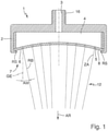
- the 1 and 2 show a sanitary shower head 1 with a shower head housing 2, which has a fluid inlet 3.
- the fluid inlet 3 optionally has a thread 16 which, for the supply of a fluid, can be screwed to a corresponding thread (not shown) of a water hose, a shower hose, a connecting pipe of a domestic water supply or the like.
- a fluid chamber 4 located in the shower head housing 2 is in fluid connection with the fluid inlet 3 .
- the fluid chamber 4 is delimited on the outlet side by a jet disc 6 designed in one piece, alternatively in multiple pieces.
- the jet disk 6 is arranged on a shower jet exit side 7 of the shower head housing 2 .
- the spray disc 6 is held on the circumference of the shower head housing 2, e.g. by the shower head housing 2 enclosing the spray disc 6 in an annular end face area RS of the spray disc 6 in a form-fitting manner.
- the jet disk 6 is formed as an elastic disk, which consists for example of a rubber, metal and/or plastic material, and can be elastically deformed by a fluid pressure in the fluid chamber 4 from an initial contour 8 into an end contour 9 .
- the initial contour 8 runs as in 1 shown curved in the direction of the fluid chamber 4 inwards.
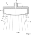
- the jet disk 6 As long as there is no fluid pressure in the fluid chamber 4, the jet disk 6 remains in its initial contour 8, as in FIG 1 shown. If the fluid pressure exceeds a certain limit pressure of, for example, 0.25 bar, the jet disc 6 assumes its final contour 9, which is curved outward, for example 2 a. For this purpose, the jet disc 6 is elastically deformed outwards in the direction away from the fluid chamber 4 by the fluid pressure. In corresponding designs, the jet disc 6 deforms in a quasi-binary manner, jumping from the initial contour 8 directly into a single final contour 9, in which it then remains even if the fluid pressure continues to rise. In alternative embodiments, the jet disc 6 deforms with increasing fluid pressure from the initial contour 8 continuously or in stages into a respective fluid-pressure-dependent final contour 9 up to a predefinable maximum final contour.
- the jet disc 6 automatically returns to the initial contour 8 due to its own elasticity or prestressing. During its return to the initial contour 8, the jet disk 6 can at least partially press fluid still in the fluid chamber 4 out of the fluid chamber 4 by using this return movement to reduce the volume of the fluid chamber 4, which had previously been reduced by the deformation of the jet disk 6 into the final contour has enlarged. Undesirable dripping after shutting off a fluid supply can be reduced as a result.
- the jet disk 6 has at least one jet outlet opening 5, in the example shown specifically several jet outlet openings 5.
- Each jet outlet opening 5 can be designed, for example, as a circular-cylindrical hole with a cylinder axis ZA, with the cylinder axis ZA forming a normal of the jet disk 6 at this point on the jet disk surface.
- the jet outlet openings 5 are in fluid connection with the fluid chamber 4.
- fluid in particular water, is under pressure in the fluid chamber 4 and from there it reaches the jet outlet openings 5, from which it flows on the shower jet outlet side 7, forming a first shower jet 12 , when the jet disk 6 is in its initial contour 8, or exits to form a second shower jet 13, if the jet disk 6 is in its final contour 9.
- the propagation angle AW is an angle that results between an edge jet direction RB of the first shower jet 12 or of the second shower jet 13 and the main propagation direction AR or a straight line GE that is parallel and offset to the latter.
- the first shower jet 12 shows the provision of the first shower jet 12 in the form of a converging shower jet. Since the exit contour 8 curves inwards in the direction of the fluid chamber 4 and the cylinder axes ZA of the spray outlet openings 5 are each a normal of the spray disc 6, the shower spray diameter of the first spray jet 12 increases immediately after it emerges from the spray outlet openings 5 and as the first shower spray continues to spread 12 in the main propagation direction AR.
- the propagation angle AW of the first shower jet 12 is, for example, between approximately -20° and -3°, in corresponding embodiments more specifically between approximately -12° and -8°.
- the second shower jet 13 in the form of a diverging shower jet. Since the end contour 9 curves outwards away from the fluid chamber 4 and the cylinder axes ZA of the jet outlet openings 5 are each a normal of the jet disc 6, the shower jet diameter of the second shower jet 13 increases as the second shower jet 13 propagates in the propagation direction AR.
- the propagation angle AW of the second shower jet 13 is, for example, between approximately +20° and +3°, in corresponding versions more specifically between approximately +12° and +8°.
- the second shower jet 13 and the first shower jet 12 differ in their propagation angle AW. Therefore, a converging shower jet or a diverging shower jet can be generated with the sanitary shower head 1 as required by adjusting the fluid pressure.
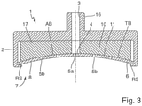
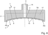
- the jet outlet openings 5 of the jet disc 6 have a number of first jet outlet openings 5a and a number of second jet outlet openings 5b. Furthermore, the fluid chamber 4 is delimited by a conforming delimitation surface 11 on a side 10 opposite the jet disk 6 .
- the boundary surface 11 is provided by an inner body 17 of the sanitary shower head 1 which is arranged opposite the spray disc 6 .
- the volume of the fluid chamber 4 is reduced by the inner body 17. The reduced volume of the fluid chamber 4 is advantageous for avoiding undesired dripping after shutting off the fluid or water supply.
- the boundary surface 11 runs at least in a partial surface area TB conforming to the initial contour 8.
- the partial surface area TB optionally forms a supporting surface area AB, which supports the jet disk 6 with its initial contour 8 inwards.
- the jet disk 6 is supported with its initial contour 8 against the boundary surface 11 in such a way that the boundary surface 11 closes the second jet outlet openings 5b, while the first jet outlet openings 5a remain open. Therefore, in this embodiment, fluid only emerges from the first jet outlet openings 5a and not also from the second jet outlet openings 5b when the jet disc 6 is in its initial contour 8 .
- the jet pattern of the shower jet when the jet disc 6 is in its end contour 9 can be that of the variant according to 2 correspond.
- the initial contour 8 in the example shown is a stable or at least metastable contour of the jet disk 6. Therefore, the jet disk 6 only deforms from its initial contour 8 when the fluid pressure exceeds a limit value, which is, for example, about 0.25 bar and alternatively one can have any other value. As long as the fluid pressure does not exceed the limit value, the contour of the jet disk 6 does not change. This can be determined by correspondingly realizing the jet disc 6 in terms of material and thickness, among other things.
- the jet disc 6 is supported with its initial contour 8 by the boundary surface 11 in such a way that the latter closes all jet outlet openings 5 of the jet disc 6 . In this case, therefore, fluid can only emerge from the jet outlet openings 5 when the jet disc 6 is deformed from its initial contour 8 into its final contour 9 .
- the final contour 9 or only the final contour 9 forms a metastable contour of the jet disc 6 instead of the initial contour 8.
- the jet outlet openings 5 of the jet disc 6 have a number of first jet outlet openings 5a and a number of second jet outlet openings 5b, with the first jet outlet openings 5a corresponding to a first fluid chamber section 4a and the second jet outlet openings 5b corresponding to a second fluid chamber section 4b.
- the first fluid chamber portion 4a is in fluid communication with the fluid inlet 3 both when the jet disk 6 assumes its initial contour 8 and when the jet disk 6 assumes its final contour 9.
- the second fluid chamber subregion 4b is in fluid communication with the fluid inlet 3 when the jet disk 6 assumes its final contour 9 .
- the second fluid chamber portion 4b is completely blocked off from the fluid inlet 3 .
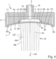
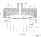
- the shower head 1 can have a convergent partial jet as the respective shower jet at a lower fluid pressure 4 and at higher fluid pressure according to a divergent solid jet figure 5 hand over.
- the jet disk 6 moves in a binary deformation movement through fluid pressure from its initial contour 8 according to FIG 4 in accordance with their final contour 9 figure 5 and automatically returns to its initial contour 8 when the fluid pressure is relieved, so that the shower head 1 optionally supplies the two associated shower jets.
- the jet disk 6 moves out of its initial contour 8 in accordance with fluid pressure in a continuous deformation movement 4 out in fluid pressure-dependent continuously changing end contours 9, so that the shower head 1 provides a shower jet, the jet pattern corresponding to continuously between the jet pattern in the output contour 8 of the jet disk 6 according to 4 and according to the jet pattern in the maximum end contour 9 of the jet disc 6 figure 5 changes.
- this has the inner body 17 on its opposite side 10 of the jet disk 6 compared to the example of FIG 3 modified form with regard to the boundary surface 11.
- the boundary surface 11 only runs in a radially outer partial surface area TB1, which corresponds to the second fluid chamber partial area 4b, conforming to the initial contour 8 of the jet disc 6, while in a central partial surface area TB2, which corresponds to the first fluid chamber partial area 4a corresponds, stepping back.
- the seal 14 consequently forms the support surface area AB, against which the jet disk 6 is supported in its initial contour 8 .
- the seal 14 is held on the inner body 17 in the example shown.
- the seal 14 is held on the jet disc 6, or a first part of the seal is held on the jet disc 6 and a second part on the inner body 17.
- the second fluid chamber section 4b is only partially blocked off from the fluid inlet 3 by the seal 14 when the jet disk 6 assumes its initial contour 8 . In this case, this also then fluid from the first fluid chamber portion 4a into the second fluid chamber portion 4b when the jet disk 6 assumes its initial contour 8 .
- the number of mandrels 15 is equal to the number of jet outlet openings 5, so that each jet outlet opening 5 is assigned a mandrel 15. In alternative embodiments, fewer mandrels 15 than jet outlet openings 5 are provided. In corresponding embodiments, each mandrel 15 protrudes into the respective jet outlet opening 5 in such a way that it protrudes from the jet outlet opening 5 when the jet disk 6 assumes its initial contour 8 . In alternative embodiments, each mandrel 15 protrudes into the jet outlet opening 5, but not out of it. When the jet disc 6 assumes its final contour 9, the mandrel 15 no longer protrudes into the jet outlet opening 5, so that the latter is completely free for the passage of shower jet-forming fluid. Limescale deposits on the jet outlet openings 5 can be avoided or removed by the mandrels 15, specifically by moving them into and out of the jet outlet openings 5.
- the cylinder axis ZA ie longitudinal axis, of the jet outlet openings 5 is not oriented normal to the jet disc 6 .
- the orientation of the cylinder axis ZA can be chosen such that, for example, a parallel shower jet or a diverging shower jet can be generated with the jet disc 6 in its initial contour 8 .
- the number and/or the arrangement of the jet outlet openings 5 of the sanitary shower head 1 according to the invention is different from the examples shown.
- the sanitary shower head 1 can have only one jet outlet opening 5 in corresponding designs in order to generate what is known as a surge jet.
- the shower head can have a large number of jet outlet openings 5, which are evenly distributed in the central area or off-centre or over the entire jet disc surface or arranged in groups, including embodiments in which the jet outlet openings 5 can be used to generate various standard shower jet types, such as a soft jet and a massage jet.
- the sanitary shower head 1 can be any combination of the variants shown Figures 1 to 7 be.
- the sanitary shower head 1 can have the seal 14 and additionally the spikes 15 .
- the invention provides a sanitary shower head which reduces undesired dripping after a water supply has been shut off, is relatively easy to manufacture and is functionally reliable.
Landscapes
- Health & Medical Sciences (AREA)
- Life Sciences & Earth Sciences (AREA)
- Engineering & Computer Science (AREA)
- Hydrology & Water Resources (AREA)
- Public Health (AREA)
- Water Supply & Treatment (AREA)
- Nozzles (AREA)
Claims (9)
- Pomme de douche sanitaire (1) avec- un boîtier de pomme de douche (2) avec une entrée de fluide (3),- une chambre de fluide (4) en liaison fluidique avec l'entrée de fluide dans le boîtier de pomme de douche et- un disque à jet (6) présentant au moins une ouverture de sortie de jet (5), qui est disposé sur un côté de sortie de jet de douche (7) du boîtier de pomme de douche et retenu côté périphérie sur le boîtier de pomme de douche et délimite côté sortie la chambre de fluide,- dans laquelle le disque à jet est formé en tant que disque élastique, qui peut être déformé élastiquement par une pression de fluide dans la chambre de fluide à partir d'un contour initial (8) dans un contour final (9),caractérisée en ce que- la chambre de fluide (4) est délimitée sur un côté (10) opposé au disque à jet (6) par une surface de délimitation (11), qui s'étend au moins dans une zone de surface partielle (TB, TB1) de manière conforme au contour initial (8) du disque à jet, et/ou- le contour initial (8) du disque à jet (6) s'étend de manière bombée vers l'intérieur en direction de la chambre de fluide (4).
- Pomme de douche sanitaire selon l'une quelconque des revendications précédentes, caractérisée en ce que le contour final du disque à jet s'étend de manière bombée vers l'extérieur.
- Pomme de douche sanitaire selon l'une quelconque des revendications précédentes, caractérisée en ce que le contour initial et/ou le contour final est un contour métastable du disque à jet.
- Pomme de douche sanitaire selon l'une quelconque des revendications précédentes, caractérisée en ce que le disque à jet est réalisé d'une seule pièce à partir d'un ou de plusieurs matériaux ou en plusieurs pièces à partir d'un ou de plusieurs matériaux.
- Pomme de douche sanitaire selon l'une quelconque des revendications précédentes, caractérisée en ce que le disque à jet fournit dans son contour initial un premier jet de douche (12) et dans son contour final un deuxième jet de douche (13), dans laquelle le premier et le deuxième jet de douche se différencient par leur angle de déploiement (AW).
- Pomme de douche sanitaire selon l'une quelconque des revendications précédentes, caractérisée en ce que le disque à jet s'appuie avec son contour initial au moins dans une zone de surface d'appui (AB) contre la surface de délimitation.
- Pomme de douche sanitaire selon la revendication 6, caractérisée en ce que- la au moins une ouverture de sortie de jet présente un nombre de premières ouvertures de sortie de jet (5a) et un nombre de deuxièmes ouvertures de sortie de jet (5b) et- le disque à jet est appuyé avec son contour initial de telle sorte que la surface de délimitation ferme le nombre de deuxièmes ouvertures de sortie de jet.
- Pomme de douche sanitaire selon la revendication 6, caractérisée en ce que- la au moins une ouverture de sortie de jet présente un nombre de premières ouvertures de sortie de jet (5a) et un nombre de deuxièmes ouvertures de sortie de jet (5b) et- le nombre de premières ouvertures de sortie de jet correspondent à une première zone partielle de chambre de fluide (4a) et le nombre de deuxièmes ouvertures de sortie de jet correspondent à une deuxième zone partielle de chambre de fluide (4b),- dans laquelle la première zone partielle de chambre de fluide est en liaison fluidique avec l'entrée de fluide aussi bien lorsque le disque à jet occupe son contour initial que lorsque le disque à jet occupe son contour final, et- dans laquelle la deuxième zone partielle de chambre de fluide est en liaison fluidique avec l'entrée de fluide lorsque le disque à jet occupe son contour final, et est entièrement ou partiellement isolée de l'entrée de fluide par un joint (14) lorsque le disque à jet occupe son contour initial.
- Pomme de douche sanitaire selon l'une quelconque des revendications précédentes, caractérisée en ce que la surface de délimitation présente au moins un mandrin (15), qui fait saillie dans la au moins une ouverture de sortie de jet, lorsque le disque à jet occupe son contour initial.
Applications Claiming Priority (1)
| Application Number | Priority Date | Filing Date | Title |
|---|---|---|---|
| DE102018210331.3A DE102018210331B3 (de) | 2018-06-25 | 2018-06-25 | Sanitärer Brausekopf |
Publications (2)
| Publication Number | Publication Date |
|---|---|
| EP3586974A1 EP3586974A1 (fr) | 2020-01-01 |
| EP3586974B1 true EP3586974B1 (fr) | 2022-02-23 |
Family
ID=67070618
Family Applications (1)
| Application Number | Title | Priority Date | Filing Date |
|---|---|---|---|
| EP19182263.4A Active EP3586974B1 (fr) | 2018-06-25 | 2019-06-25 | Pomme de douche sanitaire |
Country Status (3)
| Country | Link |
|---|---|
| EP (1) | EP3586974B1 (fr) |
| CN (1) | CN110624703B (fr) |
| DE (1) | DE102018210331B3 (fr) |
Family Cites Families (16)
| Publication number | Priority date | Publication date | Assignee | Title |
|---|---|---|---|---|
| USRE26889E (en) * | 1969-04-07 | 1970-05-19 | Adjustable spray head | |
| FR2149081A5 (fr) | 1971-07-31 | 1973-03-23 | Knapp Alfons | |
| US4211368A (en) * | 1975-06-09 | 1980-07-08 | Legros Francis R | Device for aerating and chemically activating shower water |
| DE2901013C2 (de) | 1979-01-12 | 1985-07-25 | Hans Grohe Gmbh & Co Kg, 7622 Schiltach | Brause, insbesondere Handbrause mit einer elastisch verformbaren Strahlscheibe |
| DE7904756U1 (de) | 1979-02-21 | 1980-07-31 | Hans Grohe Gmbh & Co Kg, 7622 Schiltach | Brause |
| DE3107808A1 (de) * | 1981-02-28 | 1982-09-16 | Friedrich Grohe Armaturenfabrik Gmbh & Co, 5870 Hemer | Selbstreinigender brausekopf |
| CN86205615U (zh) * | 1986-08-08 | 1987-06-24 | 郭长征 | 节水型淋浴喷头 |
| DE4300322C2 (de) | 1993-01-08 | 1995-08-03 | Burkhard Mueller | Dusch- und/oder Massagegerät |
| DE19733291A1 (de) | 1997-08-01 | 1999-02-04 | Grohe Kg Hans | Brauseeinrichtung |
| US6223998B1 (en) * | 1997-10-08 | 2001-05-01 | Charles J. Heitzman | Shower head with continuous or cycling flow rate, fast or slow pulsation and variable spray pattern |
| AU6007699A (en) * | 1998-10-22 | 2000-05-08 | Yosuke Naito | Showerhead |
| JP2000262427A (ja) * | 1999-03-17 | 2000-09-26 | Toto Ltd | シャワー装置 |
| DE10313501A1 (de) | 2003-03-25 | 2004-10-14 | Dieter Wildfang Gmbh | Sanitäre Wasserauslaufeinheit, insbesondere Strahlregler oder Brause |
| CN201586577U (zh) * | 2010-01-12 | 2010-09-22 | 厦门松霖科技有限公司 | 一种按钮切换花洒 |
| JP2012152470A (ja) * | 2011-01-27 | 2012-08-16 | Lixil Corp | シャワー吐水装置 |
| DE102016219551B4 (de) * | 2016-10-07 | 2022-01-05 | Hansgrohe Se | Brausestrahlerzeugungsvorrichtung |
-
2018
- 2018-06-25 DE DE102018210331.3A patent/DE102018210331B3/de not_active Expired - Fee Related
-
2019
- 2019-06-25 EP EP19182263.4A patent/EP3586974B1/fr active Active
- 2019-06-25 CN CN201910555014.2A patent/CN110624703B/zh active Active
Also Published As
| Publication number | Publication date |
|---|---|
| EP3586974A1 (fr) | 2020-01-01 |
| DE102018210331B3 (de) | 2019-08-22 |
| CN110624703A (zh) | 2019-12-31 |
| CN110624703B (zh) | 2022-01-07 |
Similar Documents
| Publication | Publication Date | Title |
|---|---|---|
| DE4105183C5 (de) | Brausekopf | |
| EP2664719B1 (fr) | Élément d'installation sanitaire | |
| EP1700636B1 (fr) | Pomme de douche | |
| EP3305412B1 (fr) | Dispositif de production de jets | |
| EP3517212B1 (fr) | Dispositif de génération de jets de douche à vanne de surpression | |
| CH648771A5 (de) | Brausekopf. | |
| EP3338898B1 (fr) | Dispositif de sortie jets du pommeau de douche et pommeau de douche correspondant | |
| DE2234669B2 (de) | Dusenbaugruppe | |
| EP3276231A1 (fr) | Dispositif de production de jets | |
| EP3586974B1 (fr) | Pomme de douche sanitaire | |
| EP3936748A1 (fr) | Soupape de réglage autonome | |
| EP3517211B1 (fr) | Pomme de douche à vanne de surpression | |
| DE2901013C2 (de) | Brause, insbesondere Handbrause mit einer elastisch verformbaren Strahlscheibe | |
| DE102013014942B4 (de) | Brausekopf für eine Sanitärbrause | |
| DE2854572A1 (de) | Durch fluessigkeitsdruck betaetigbares pilotventil | |
| DE19504652A1 (de) | Vorrichtung zur Erzeugung eines Flüssigkeitsstrahls | |
| EP3702541B1 (fr) | Pomme de douche pour une armature sanitaire dotée d'un ressort de rappel | |
| DE2200671A1 (de) | Selbstschliessendes Absperrorgan | |
| EP3677340B1 (fr) | Pomme de douche pourvue d'un dispositif de retenue de disque diffuseur | |
| DE112019004251T5 (de) | Wasserauslassdüse und Wasserstrahleinrichtung mit derselben | |
| DE102021200951B3 (de) | Sprühdüse und Satz mit mehreren Sprühdüsen | |
| DE2830201C2 (fr) | ||
| WO2023180466A1 (fr) | Pomme de douche sanitaire | |
| WO2023110370A1 (fr) | Dispositif de génération de jet de douche doté d'un dispositif anti-goutte | |
| DE2105632B2 (de) | Kopf- und koerperbrause |
Legal Events
| Date | Code | Title | Description |
|---|---|---|---|
| PUAI | Public reference made under article 153(3) epc to a published international application that has entered the european phase |
Free format text: ORIGINAL CODE: 0009012 |
|
| STAA | Information on the status of an ep patent application or granted ep patent |
Free format text: STATUS: THE APPLICATION HAS BEEN PUBLISHED |
|
| AK | Designated contracting states |
Kind code of ref document: A1 Designated state(s): AL AT BE BG CH CY CZ DE DK EE ES FI FR GB GR HR HU IE IS IT LI LT LU LV MC MK MT NL NO PL PT RO RS SE SI SK SM TR |
|
| AX | Request for extension of the european patent |
Extension state: BA ME |
|
| STAA | Information on the status of an ep patent application or granted ep patent |
Free format text: STATUS: REQUEST FOR EXAMINATION WAS MADE |
|
| 17P | Request for examination filed |
Effective date: 20200624 |
|
| RBV | Designated contracting states (corrected) |
Designated state(s): AL AT BE BG CH CY CZ DE DK EE ES FI FR GB GR HR HU IE IS IT LI LT LU LV MC MK MT NL NO PL PT RO RS SE SI SK SM TR |
|
| GRAP | Despatch of communication of intention to grant a patent |
Free format text: ORIGINAL CODE: EPIDOSNIGR1 |
|
| STAA | Information on the status of an ep patent application or granted ep patent |
Free format text: STATUS: GRANT OF PATENT IS INTENDED |
|
| RIC1 | Information provided on ipc code assigned before grant |
Ipc: B05B 1/26 20060101ALI20210817BHEP Ipc: B05B 1/30 20060101ALI20210817BHEP Ipc: B05B 1/28 20060101ALI20210817BHEP Ipc: B05B 15/522 20180101ALI20210817BHEP Ipc: B05B 15/652 20180101ALI20210817BHEP Ipc: E03C 1/04 20060101ALI20210817BHEP Ipc: B05B 15/528 20180101ALI20210817BHEP Ipc: B05B 1/18 20060101AFI20210817BHEP |
|
| INTG | Intention to grant announced |
Effective date: 20210910 |
|
| GRAJ | Information related to disapproval of communication of intention to grant by the applicant or resumption of examination proceedings by the epo deleted |
Free format text: ORIGINAL CODE: EPIDOSDIGR1 |
|
| STAA | Information on the status of an ep patent application or granted ep patent |
Free format text: STATUS: REQUEST FOR EXAMINATION WAS MADE |
|
| GRAP | Despatch of communication of intention to grant a patent |
Free format text: ORIGINAL CODE: EPIDOSNIGR1 |
|
| STAA | Information on the status of an ep patent application or granted ep patent |
Free format text: STATUS: GRANT OF PATENT IS INTENDED |
|
| INTC | Intention to grant announced (deleted) | ||
| INTG | Intention to grant announced |
Effective date: 20211022 |
|
| GRAS | Grant fee paid |
Free format text: ORIGINAL CODE: EPIDOSNIGR3 |
|
| GRAA | (expected) grant |
Free format text: ORIGINAL CODE: 0009210 |
|
| STAA | Information on the status of an ep patent application or granted ep patent |
Free format text: STATUS: THE PATENT HAS BEEN GRANTED |
|
| AK | Designated contracting states |
Kind code of ref document: B1 Designated state(s): AL AT BE BG CH CY CZ DE DK EE ES FI FR GB GR HR HU IE IS IT LI LT LU LV MC MK MT NL NO PL PT RO RS SE SI SK SM TR |
|
| REG | Reference to a national code |
Ref country code: GB Ref legal event code: FG4D Free format text: NOT ENGLISH |
|
| REG | Reference to a national code |
Ref country code: CH Ref legal event code: EP |
|
| REG | Reference to a national code |
Ref country code: AT Ref legal event code: REF Ref document number: 1470018 Country of ref document: AT Kind code of ref document: T Effective date: 20220315 |
|
| REG | Reference to a national code |
Ref country code: IE Ref legal event code: FG4D Free format text: LANGUAGE OF EP DOCUMENT: GERMAN |
|
| REG | Reference to a national code |
Ref country code: DE Ref legal event code: R096 Ref document number: 502019003465 Country of ref document: DE |
|
| REG | Reference to a national code |
Ref country code: LT Ref legal event code: MG9D |
|
| REG | Reference to a national code |
Ref country code: NL Ref legal event code: MP Effective date: 20220223 |
|
| PG25 | Lapsed in a contracting state [announced via postgrant information from national office to epo] |
Ref country code: SE Free format text: LAPSE BECAUSE OF FAILURE TO SUBMIT A TRANSLATION OF THE DESCRIPTION OR TO PAY THE FEE WITHIN THE PRESCRIBED TIME-LIMIT Effective date: 20220223 Ref country code: RS Free format text: LAPSE BECAUSE OF FAILURE TO SUBMIT A TRANSLATION OF THE DESCRIPTION OR TO PAY THE FEE WITHIN THE PRESCRIBED TIME-LIMIT Effective date: 20220223 Ref country code: PT Free format text: LAPSE BECAUSE OF FAILURE TO SUBMIT A TRANSLATION OF THE DESCRIPTION OR TO PAY THE FEE WITHIN THE PRESCRIBED TIME-LIMIT Effective date: 20220623 Ref country code: NO Free format text: LAPSE BECAUSE OF FAILURE TO SUBMIT A TRANSLATION OF THE DESCRIPTION OR TO PAY THE FEE WITHIN THE PRESCRIBED TIME-LIMIT Effective date: 20220523 Ref country code: NL Free format text: LAPSE BECAUSE OF FAILURE TO SUBMIT A TRANSLATION OF THE DESCRIPTION OR TO PAY THE FEE WITHIN THE PRESCRIBED TIME-LIMIT Effective date: 20220223 Ref country code: LT Free format text: LAPSE BECAUSE OF FAILURE TO SUBMIT A TRANSLATION OF THE DESCRIPTION OR TO PAY THE FEE WITHIN THE PRESCRIBED TIME-LIMIT Effective date: 20220223 Ref country code: HR Free format text: LAPSE BECAUSE OF FAILURE TO SUBMIT A TRANSLATION OF THE DESCRIPTION OR TO PAY THE FEE WITHIN THE PRESCRIBED TIME-LIMIT Effective date: 20220223 Ref country code: ES Free format text: LAPSE BECAUSE OF FAILURE TO SUBMIT A TRANSLATION OF THE DESCRIPTION OR TO PAY THE FEE WITHIN THE PRESCRIBED TIME-LIMIT Effective date: 20220223 Ref country code: BG Free format text: LAPSE BECAUSE OF FAILURE TO SUBMIT A TRANSLATION OF THE DESCRIPTION OR TO PAY THE FEE WITHIN THE PRESCRIBED TIME-LIMIT Effective date: 20220523 |
|
| PG25 | Lapsed in a contracting state [announced via postgrant information from national office to epo] |
Ref country code: PL Free format text: LAPSE BECAUSE OF FAILURE TO SUBMIT A TRANSLATION OF THE DESCRIPTION OR TO PAY THE FEE WITHIN THE PRESCRIBED TIME-LIMIT Effective date: 20220223 Ref country code: LV Free format text: LAPSE BECAUSE OF FAILURE TO SUBMIT A TRANSLATION OF THE DESCRIPTION OR TO PAY THE FEE WITHIN THE PRESCRIBED TIME-LIMIT Effective date: 20220223 Ref country code: GR Free format text: LAPSE BECAUSE OF FAILURE TO SUBMIT A TRANSLATION OF THE DESCRIPTION OR TO PAY THE FEE WITHIN THE PRESCRIBED TIME-LIMIT Effective date: 20220524 Ref country code: FI Free format text: LAPSE BECAUSE OF FAILURE TO SUBMIT A TRANSLATION OF THE DESCRIPTION OR TO PAY THE FEE WITHIN THE PRESCRIBED TIME-LIMIT Effective date: 20220223 |
|
| PG25 | Lapsed in a contracting state [announced via postgrant information from national office to epo] |
Ref country code: IS Free format text: LAPSE BECAUSE OF FAILURE TO SUBMIT A TRANSLATION OF THE DESCRIPTION OR TO PAY THE FEE WITHIN THE PRESCRIBED TIME-LIMIT Effective date: 20220623 |
|
| PG25 | Lapsed in a contracting state [announced via postgrant information from national office to epo] |
Ref country code: SM Free format text: LAPSE BECAUSE OF FAILURE TO SUBMIT A TRANSLATION OF THE DESCRIPTION OR TO PAY THE FEE WITHIN THE PRESCRIBED TIME-LIMIT Effective date: 20220223 Ref country code: SK Free format text: LAPSE BECAUSE OF FAILURE TO SUBMIT A TRANSLATION OF THE DESCRIPTION OR TO PAY THE FEE WITHIN THE PRESCRIBED TIME-LIMIT Effective date: 20220223 Ref country code: RO Free format text: LAPSE BECAUSE OF FAILURE TO SUBMIT A TRANSLATION OF THE DESCRIPTION OR TO PAY THE FEE WITHIN THE PRESCRIBED TIME-LIMIT Effective date: 20220223 Ref country code: EE Free format text: LAPSE BECAUSE OF FAILURE TO SUBMIT A TRANSLATION OF THE DESCRIPTION OR TO PAY THE FEE WITHIN THE PRESCRIBED TIME-LIMIT Effective date: 20220223 Ref country code: DK Free format text: LAPSE BECAUSE OF FAILURE TO SUBMIT A TRANSLATION OF THE DESCRIPTION OR TO PAY THE FEE WITHIN THE PRESCRIBED TIME-LIMIT Effective date: 20220223 Ref country code: CZ Free format text: LAPSE BECAUSE OF FAILURE TO SUBMIT A TRANSLATION OF THE DESCRIPTION OR TO PAY THE FEE WITHIN THE PRESCRIBED TIME-LIMIT Effective date: 20220223 |
|
| REG | Reference to a national code |
Ref country code: DE Ref legal event code: R097 Ref document number: 502019003465 Country of ref document: DE |
|
| PG25 | Lapsed in a contracting state [announced via postgrant information from national office to epo] |
Ref country code: AL Free format text: LAPSE BECAUSE OF FAILURE TO SUBMIT A TRANSLATION OF THE DESCRIPTION OR TO PAY THE FEE WITHIN THE PRESCRIBED TIME-LIMIT Effective date: 20220223 |
|
| PLBE | No opposition filed within time limit |
Free format text: ORIGINAL CODE: 0009261 |
|
| STAA | Information on the status of an ep patent application or granted ep patent |
Free format text: STATUS: NO OPPOSITION FILED WITHIN TIME LIMIT |
|
| PG25 | Lapsed in a contracting state [announced via postgrant information from national office to epo] |
Ref country code: MC Free format text: LAPSE BECAUSE OF FAILURE TO SUBMIT A TRANSLATION OF THE DESCRIPTION OR TO PAY THE FEE WITHIN THE PRESCRIBED TIME-LIMIT Effective date: 20220223 |
|
| REG | Reference to a national code |
Ref country code: CH Ref legal event code: PL |
|
| 26N | No opposition filed |
Effective date: 20221124 |
|
| REG | Reference to a national code |
Ref country code: BE Ref legal event code: MM Effective date: 20220630 |
|
| PG25 | Lapsed in a contracting state [announced via postgrant information from national office to epo] |
Ref country code: SI Free format text: LAPSE BECAUSE OF FAILURE TO SUBMIT A TRANSLATION OF THE DESCRIPTION OR TO PAY THE FEE WITHIN THE PRESCRIBED TIME-LIMIT Effective date: 20220223 |
|
| PG25 | Lapsed in a contracting state [announced via postgrant information from national office to epo] |
Ref country code: LU Free format text: LAPSE BECAUSE OF NON-PAYMENT OF DUE FEES Effective date: 20220625 Ref country code: LI Free format text: LAPSE BECAUSE OF NON-PAYMENT OF DUE FEES Effective date: 20220630 Ref country code: IE Free format text: LAPSE BECAUSE OF NON-PAYMENT OF DUE FEES Effective date: 20220625 Ref country code: CH Free format text: LAPSE BECAUSE OF NON-PAYMENT OF DUE FEES Effective date: 20220630 |
|
| PG25 | Lapsed in a contracting state [announced via postgrant information from national office to epo] |
Ref country code: BE Free format text: LAPSE BECAUSE OF NON-PAYMENT OF DUE FEES Effective date: 20220630 |
|
| PGFP | Annual fee paid to national office [announced via postgrant information from national office to epo] |
Ref country code: FR Payment date: 20230622 Year of fee payment: 5 Ref country code: DE Payment date: 20230627 Year of fee payment: 5 |
|
| PGFP | Annual fee paid to national office [announced via postgrant information from national office to epo] |
Ref country code: IT Payment date: 20230620 Year of fee payment: 5 |
|
| GBPC | Gb: european patent ceased through non-payment of renewal fee |
Effective date: 20230625 |
|
| PG25 | Lapsed in a contracting state [announced via postgrant information from national office to epo] |
Ref country code: MK Free format text: LAPSE BECAUSE OF FAILURE TO SUBMIT A TRANSLATION OF THE DESCRIPTION OR TO PAY THE FEE WITHIN THE PRESCRIBED TIME-LIMIT Effective date: 20220223 Ref country code: CY Free format text: LAPSE BECAUSE OF FAILURE TO SUBMIT A TRANSLATION OF THE DESCRIPTION OR TO PAY THE FEE WITHIN THE PRESCRIBED TIME-LIMIT Effective date: 20220223 Ref country code: GB Free format text: LAPSE BECAUSE OF NON-PAYMENT OF DUE FEES Effective date: 20230625 |