EP3936748A1 - Soupape de réglage autonome - Google Patents
Soupape de réglage autonome Download PDFInfo
- Publication number
- EP3936748A1 EP3936748A1 EP21195225.4A EP21195225A EP3936748A1 EP 3936748 A1 EP3936748 A1 EP 3936748A1 EP 21195225 A EP21195225 A EP 21195225A EP 3936748 A1 EP3936748 A1 EP 3936748A1
- Authority
- EP
- European Patent Office
- Prior art keywords
- main valve
- valve piston
- chamber
- wire element
- pilot
- Prior art date
- Legal status (The legal status is an assumption and is not a legal conclusion. Google has not performed a legal analysis and makes no representation as to the accuracy of the status listed.)
- Granted
Links
- 238000004140 cleaning Methods 0.000 claims abstract description 38
- 239000007788 liquid Substances 0.000 claims abstract description 5
- 238000007789 sealing Methods 0.000 claims description 29
- 230000006835 compression Effects 0.000 claims description 9
- 238000007906 compression Methods 0.000 claims description 9
- 238000007790 scraping Methods 0.000 claims description 5
- 230000001276 controlling effect Effects 0.000 abstract description 3
- 230000001105 regulatory effect Effects 0.000 abstract description 2
- XLYOFNOQVPJJNP-UHFFFAOYSA-N water Substances O XLYOFNOQVPJJNP-UHFFFAOYSA-N 0.000 description 8
- 238000011161 development Methods 0.000 description 5
- 230000018109 developmental process Effects 0.000 description 5
- 239000012528 membrane Substances 0.000 description 5
- 230000000694 effects Effects 0.000 description 2
- 239000013013 elastic material Substances 0.000 description 2
- 239000012535 impurity Substances 0.000 description 2
- 238000004519 manufacturing process Methods 0.000 description 2
- 235000008733 Citrus aurantifolia Nutrition 0.000 description 1
- 235000011941 Tilia x europaea Nutrition 0.000 description 1
- 239000000356 contaminant Substances 0.000 description 1
- 230000001419 dependent effect Effects 0.000 description 1
- 230000009977 dual effect Effects 0.000 description 1
- 238000005516 engineering process Methods 0.000 description 1
- 239000008233 hard water Substances 0.000 description 1
- 239000004571 lime Substances 0.000 description 1
- 230000007774 longterm Effects 0.000 description 1
- 230000035515 penetration Effects 0.000 description 1
- 230000003746 surface roughness Effects 0.000 description 1
Images


Classifications
-
- F—MECHANICAL ENGINEERING; LIGHTING; HEATING; WEAPONS; BLASTING
- F16—ENGINEERING ELEMENTS AND UNITS; GENERAL MEASURES FOR PRODUCING AND MAINTAINING EFFECTIVE FUNCTIONING OF MACHINES OR INSTALLATIONS; THERMAL INSULATION IN GENERAL
- F16K—VALVES; TAPS; COCKS; ACTUATING-FLOATS; DEVICES FOR VENTING OR AERATING
- F16K31/00—Actuating devices; Operating means; Releasing devices
- F16K31/12—Actuating devices; Operating means; Releasing devices actuated by fluid
- F16K31/36—Actuating devices; Operating means; Releasing devices actuated by fluid in which fluid from the circuit is constantly supplied to the fluid motor
- F16K31/38—Actuating devices; Operating means; Releasing devices actuated by fluid in which fluid from the circuit is constantly supplied to the fluid motor in which the fluid works directly on both sides of the fluid motor, one side being connected by means of a restricted passage and the motor being actuated by operating a discharge from that side
- F16K31/385—Actuating devices; Operating means; Releasing devices actuated by fluid in which fluid from the circuit is constantly supplied to the fluid motor in which the fluid works directly on both sides of the fluid motor, one side being connected by means of a restricted passage and the motor being actuated by operating a discharge from that side the fluid acting on a diaphragm
- F16K31/3855—Actuating devices; Operating means; Releasing devices actuated by fluid in which fluid from the circuit is constantly supplied to the fluid motor in which the fluid works directly on both sides of the fluid motor, one side being connected by means of a restricted passage and the motor being actuated by operating a discharge from that side the fluid acting on a diaphragm the discharge being effected through the diaphragm and being blockable by a mechanically-actuated member making contact with the diaphragm
-
- F—MECHANICAL ENGINEERING; LIGHTING; HEATING; WEAPONS; BLASTING
- F16—ENGINEERING ELEMENTS AND UNITS; GENERAL MEASURES FOR PRODUCING AND MAINTAINING EFFECTIVE FUNCTIONING OF MACHINES OR INSTALLATIONS; THERMAL INSULATION IN GENERAL
- F16K—VALVES; TAPS; COCKS; ACTUATING-FLOATS; DEVICES FOR VENTING OR AERATING
- F16K21/00—Fluid-delivery valves, e.g. self-closing valves
- F16K21/04—Self-closing valves, i.e. closing automatically after operation
- F16K21/06—Self-closing valves, i.e. closing automatically after operation in which the closing movement, either retarded or not, starts immediately after opening
- F16K21/12—Self-closing valves, i.e. closing automatically after operation in which the closing movement, either retarded or not, starts immediately after opening with hydraulically-operated opening means; with arrangements for pressure relief before opening
-
- F—MECHANICAL ENGINEERING; LIGHTING; HEATING; WEAPONS; BLASTING
- F16—ENGINEERING ELEMENTS AND UNITS; GENERAL MEASURES FOR PRODUCING AND MAINTAINING EFFECTIVE FUNCTIONING OF MACHINES OR INSTALLATIONS; THERMAL INSULATION IN GENERAL
- F16K—VALVES; TAPS; COCKS; ACTUATING-FLOATS; DEVICES FOR VENTING OR AERATING
- F16K31/00—Actuating devices; Operating means; Releasing devices
- F16K31/12—Actuating devices; Operating means; Releasing devices actuated by fluid
- F16K31/122—Actuating devices; Operating means; Releasing devices actuated by fluid the fluid acting on a piston
- F16K31/1221—Actuating devices; Operating means; Releasing devices actuated by fluid the fluid acting on a piston one side of the piston being spring-loaded
-
- F—MECHANICAL ENGINEERING; LIGHTING; HEATING; WEAPONS; BLASTING
- F16—ENGINEERING ELEMENTS AND UNITS; GENERAL MEASURES FOR PRODUCING AND MAINTAINING EFFECTIVE FUNCTIONING OF MACHINES OR INSTALLATIONS; THERMAL INSULATION IN GENERAL
- F16K—VALVES; TAPS; COCKS; ACTUATING-FLOATS; DEVICES FOR VENTING OR AERATING
- F16K31/00—Actuating devices; Operating means; Releasing devices
- F16K31/12—Actuating devices; Operating means; Releasing devices actuated by fluid
- F16K31/18—Actuating devices; Operating means; Releasing devices actuated by fluid actuated by a float
- F16K31/34—Actuating devices; Operating means; Releasing devices actuated by fluid actuated by a float acting on pilot valve controlling the cut-off apparatus
-
- F—MECHANICAL ENGINEERING; LIGHTING; HEATING; WEAPONS; BLASTING
- F16—ENGINEERING ELEMENTS AND UNITS; GENERAL MEASURES FOR PRODUCING AND MAINTAINING EFFECTIVE FUNCTIONING OF MACHINES OR INSTALLATIONS; THERMAL INSULATION IN GENERAL
- F16K—VALVES; TAPS; COCKS; ACTUATING-FLOATS; DEVICES FOR VENTING OR AERATING
- F16K31/00—Actuating devices; Operating means; Releasing devices
- F16K31/12—Actuating devices; Operating means; Releasing devices actuated by fluid
- F16K31/36—Actuating devices; Operating means; Releasing devices actuated by fluid in which fluid from the circuit is constantly supplied to the fluid motor
- F16K31/38—Actuating devices; Operating means; Releasing devices actuated by fluid in which fluid from the circuit is constantly supplied to the fluid motor in which the fluid works directly on both sides of the fluid motor, one side being connected by means of a restricted passage and the motor being actuated by operating a discharge from that side
- F16K31/383—Actuating devices; Operating means; Releasing devices actuated by fluid in which fluid from the circuit is constantly supplied to the fluid motor in which the fluid works directly on both sides of the fluid motor, one side being connected by means of a restricted passage and the motor being actuated by operating a discharge from that side the fluid acting on a piston
-
- F—MECHANICAL ENGINEERING; LIGHTING; HEATING; WEAPONS; BLASTING
- F16—ENGINEERING ELEMENTS AND UNITS; GENERAL MEASURES FOR PRODUCING AND MAINTAINING EFFECTIVE FUNCTIONING OF MACHINES OR INSTALLATIONS; THERMAL INSULATION IN GENERAL
- F16K—VALVES; TAPS; COCKS; ACTUATING-FLOATS; DEVICES FOR VENTING OR AERATING
- F16K31/00—Actuating devices; Operating means; Releasing devices
- F16K31/44—Mechanical actuating means
- F16K31/52—Mechanical actuating means with crank, eccentric, or cam
- F16K31/524—Mechanical actuating means with crank, eccentric, or cam with a cam
- F16K31/52491—Mechanical actuating means with crank, eccentric, or cam with a cam comprising a diaphragm cut-off apparatus
-
- F—MECHANICAL ENGINEERING; LIGHTING; HEATING; WEAPONS; BLASTING
- F16—ENGINEERING ELEMENTS AND UNITS; GENERAL MEASURES FOR PRODUCING AND MAINTAINING EFFECTIVE FUNCTIONING OF MACHINES OR INSTALLATIONS; THERMAL INSULATION IN GENERAL
- F16K—VALVES; TAPS; COCKS; ACTUATING-FLOATS; DEVICES FOR VENTING OR AERATING
- F16K17/00—Safety valves; Equalising valves, e.g. pressure relief valves
- F16K17/02—Safety valves; Equalising valves, e.g. pressure relief valves opening on surplus pressure on one side; closing on insufficient pressure on one side
- F16K17/04—Safety valves; Equalising valves, e.g. pressure relief valves opening on surplus pressure on one side; closing on insufficient pressure on one side spring-loaded
- F16K17/10—Safety valves; Equalising valves, e.g. pressure relief valves opening on surplus pressure on one side; closing on insufficient pressure on one side spring-loaded with auxiliary valve for fluid operation of the main valve
- F16K17/105—Safety valves; Equalising valves, e.g. pressure relief valves opening on surplus pressure on one side; closing on insufficient pressure on one side spring-loaded with auxiliary valve for fluid operation of the main valve using choking or throttling means to control the fluid operation of the main valve
-
- F—MECHANICAL ENGINEERING; LIGHTING; HEATING; WEAPONS; BLASTING
- F16—ENGINEERING ELEMENTS AND UNITS; GENERAL MEASURES FOR PRODUCING AND MAINTAINING EFFECTIVE FUNCTIONING OF MACHINES OR INSTALLATIONS; THERMAL INSULATION IN GENERAL
- F16K—VALVES; TAPS; COCKS; ACTUATING-FLOATS; DEVICES FOR VENTING OR AERATING
- F16K31/00—Actuating devices; Operating means; Releasing devices
- F16K31/12—Actuating devices; Operating means; Releasing devices actuated by fluid
- F16K31/42—Actuating devices; Operating means; Releasing devices actuated by fluid by means of electrically-actuated members in the supply or discharge conduits of the fluid motor
- F16K31/423—Actuating devices; Operating means; Releasing devices actuated by fluid by means of electrically-actuated members in the supply or discharge conduits of the fluid motor the actuated members consisting of multiple way valves
- F16K31/426—Actuating devices; Operating means; Releasing devices actuated by fluid by means of electrically-actuated members in the supply or discharge conduits of the fluid motor the actuated members consisting of multiple way valves the actuated valves being cylindrical sliding valves
Definitions
- the invention relates to a control valve controlled by its own medium for a liquid flow control according to the preamble of patent claim 1.
- a control valve of this type controlled by its own medium, can be used, for example, in a sanitary fitting, by means of which the water outlet for, for example, a tub drain, a tub shower or an overhead shower can be switched on or off.
- the water pressure on the inlet side is routed via a pilot line to a pilot valve, which forms a control component for a main valve.
- the pilot valve uses a control chamber above a main valve piston to open or close the main valve.
- the control valve consists of a main valve and a pilot valve.
- the main valve has a main valve piston that can be stroke-adjusted in the axial direction and a main valve seat that interacts with it.
- An adjustable flow gap is defined between the main valve piston and the main valve seat to regulate the flow of liquid.
- the main valve piston can be controlled with the pilot valve.
- the pilot valve has a control chamber on the side of the main valve piston facing away from the main valve seat. This is fluidically connected to the inflow chamber via a pilot line in the main valve piston and to the outflow chamber via a pressure relief line.
- the pilot valve also has a pilot valve piston whose stroke can be adjusted manually or via an electromagnet.
- the pilot line can become clogged with dirt, such as limescale deposits.
- dirt such as limescale deposits.
- To remove such impurities is from the DE 36 42 669 A1 known to lead a stationary cleaning wire element in the axial direction with a hole clearance through the pilot line.
- the pilot line integrated therein can be moved along the stationary cleaning wire element, as a result of which the impurities in the pilot line can be detached.
- the object of the invention is to provide a control valve controlled by its own medium, in which the operational reliability can be increased in a simple manner.
- the cleaning wire element according to the characterizing part of patent claim 1 has an actuating contour which can be brought into sliding contact with a counter-contour formed on the main valve piston, at least during stroke adjustment.
- the wire-side actuating contour and the piston-side counter-contour are geometrically designed in such a way that they slide along one another while a transverse force acting on the wire element builds up. The application of lateral force can cause the wire element to collide with the inner circumference of the pilot line, as a result of which any limescale deposits that may be present can be scraped off.
- the cleaning wire element can have a diameter in the range from 0.3 to 0.5 mm, specifically with an inner diameter of the pilot line in the range from 0.7 to 0.9 mm.
- the cleaning wire element can have a wire base body which is straight throughout in the direction of the longitudinal extent of the wire and from which the actuating contour projects in the transverse direction.
- the actuating contour can be formed on a free end of the cleaning wire element.
- the free end of the wire element can protrude beyond a pilot line opening facing the inlet chamber.
- the free end of the wire can be freely movable, ie spaced apart from the boundary walls of the inlet chamber via a clearance.
- a particularly simple wire geometry results when the free end of the wire is continuously straight and is set off at an inclined angle relative to the wire base body, which can be in a range from 0 to 45°, in particular 20°.
- the cleaning wire element can have a round profile or a polygonal profile, preferably a square profile. Studies have shown that with a square profile, the edges can be made sufficiently sharp to produce a good scraping effect. To increase the scraping properties, the polygonal profiled cleaning element can be twisted in a spiral shape.
- the cleaning wire element can be wound spirally, especially in the area of the wire base body.
- the adjoining free end of the wire can, as already mentioned above, be designed in a straight line with a consistently constant wire cross-section.
- the cleaning wire element, in particular its wire base body can have a corrugated profile. In order to increase the cleaning effect, it is preferred if the wave height of the wave profile increases in the direction of the pilot line opening facing the inflow chamber.
- the free end of the wire in a straight line with a wire cross section that remains constant throughout.
- the free end of the wire can also be formed as an angled loop.
- a helical compression spring can be supported in the control chamber between the main valve piston and a valve housing wall axially remote therefrom, which can extend around the pilot valve piston.
- an additional spring force i.e. a closing force
- the helical compression spring may be dual function integrally and integrally extended with the cleaning wire member extending radially outward of the helical compression spring through the pilot conduit.
- the main valve seat can have a sealing surface that faces the main valve piston and is designed to be completely flat. This results in a particularly large-area sealing zone with comparatively low surface pressure between the opposing sealing partners. Any surface irregularities or contaminants in the sealing zone can therefore already lead to leaks.
- the sealing surface facing the main valve piston can preferably be divided into a planar base surface transverse to the axial direction and a sealing edge protruding therefrom in the direction of the main valve piston.
- the sealing edge can preferably be arranged radially on the inside and the annular base surface can be arranged radially on the outside. This ensures that the sealing edge of the main valve seat can be pressed into the opposite sealing partner, which is preferably made of an elastic material, even at low water pressures.
- the elastic material of the sealing partner interacting with the main valve seat can preferably have a Shore/IRHD hardness of 40° to 70° exhibit. Any surface irregularities that may be present on the elastic counterpart can be sealed off by the sealing edge positioned in front. By means of the base area set back compared to the sealing edge, an overloading of the elastic counterpart, which can preferably occur with frequent and long usage, can be prevented.
- the flat base serves as an additional sealing surface, which also experiences a certain penetration depth into the elastic counterpart on the main valve piston, but avoids excessive surface pressure/stress on the elastic sealing surface.
- a highly polished sealing surface is advantageous on the one hand (so that the low surface roughness counteracts lime adhesion), and on the other hand the sharp sealing edge acts as a limescale breaker that breaks up the deposits causes the elastic counterpart of the main valve piston to flake off and thus ensures a permanent sealing function.
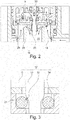
- the control valve shown has a main valve 11 ( 2 ), with which a liquid flow between an inlet chamber 13 and an outlet chamber 15 can be regulated, and a pilot valve 17 controlling the main valve 11 ( 3 ) which can be used as a control component for the main valve 11 .
- That in the 1 Main valve 11 shown is by one in one Valve housing 19 in the axial direction adjustable main valve piston 21 and composed of a main valve seat 23 cooperating therewith. In the 1 the main valve piston 21 is shown in its open position, whereby a valve gap 25 for flow control is exposed.
- the inlet chamber 13 is arranged radially outside the hollow-cylindrical main valve seat 23 , while the outlet chamber 15 is located radially inside the main valve seat 23 .
- the main valve piston 21 is in the 1 embodied in two parts, namely with a lower elastic membrane 27 to which a membrane plate 29, which is rigid in comparison thereto, is fastened.
- the membrane 27 is fastened to the valve housing 19 radially on the outside.
- the control chamber 5 is located on the side of the main valve piston 21 facing away from the main valve seat 23 in the axial direction.
- pilot valve 17 ( 3 ) A pilot valve piston 33, which is manually adjustable in the axial direction, according to the 1 either by means of a push button 35 or alternatively by means of a rotary knob 37.
- the pilot valve piston 33 is in the 1 guided centrally through the pressure relief line 31 in the main valve piston 21 .
- the pilot valve piston 33 can be adjusted between a closed position and an open position and into an intermediate controlling position.
- the pilot valve piston 33 is shown in its open position, in which the pressure relief line 31 is open. In this way, pressure equalization occurs between the control chamber 5 and the discharge chamber 15 .
- the main valve piston 21, as shown is moved upwards in an opening direction due to the water pressure present in the inlet chamber 13.
- a helical compression spring 41 is additionally arranged in the control chamber 5, which extends concentrically around the pilot valve piston 33 and is supported between the main valve piston 21 and an axially opposite valve housing wall 43.
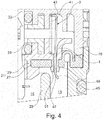
- the cleaning wire 3 does not have a round profile but a square profile. To increase the scraping properties, the square profile is twisted in a spiral.
- the cleaning wire 3 is spirally wound on its wire base body 49 .
- the adjoining free wire end 45 is, as in the previous embodiment variants, formed in a straight line with a consistently constant wire cross-section.
- the cleaning wire 3 has a corrugated profile 53 on its wire base body 49 .
- the wave height of the wave profile 53 increases in the direction of the pilot line opening 47 facing the inflow chamber 13 .
- the free wire end 45 is no longer straight but has an angled loop 55.
- the main valve seat 23 has a sealing surface 57 facing the main valve piston 21, which is divided into two, namely a base surface 59 that is planar transversely to the axial direction and a sealing edge 61 that protrudes from it in the direction of the main valve piston 21.
- the sealing edge 61 is radially inward and the base surface 59 is radial arranged outside.
- the base 59 acts as a travel stop to limit the stroke of the main valve piston 21 .
- the sealing edge 61 can also be arranged radially on the outside and the base 59 can be arranged radially on the inside. Furthermore, the sealing edge 61 can also be arranged centrally when viewed in the radial direction, ie it can be delimited both radially on the outside and radially on the inside by the planar base surface 59 .
- pilot line 55 loop 3 cleaning wire element 57 sealing surface 5 control chamber 59
- Floor space 11 main valve 61 sealing edge 13 inlet chamber f lateral force 15 drain chamber 17
- pilot valve 19 valve body 21
- main valve piston 23 main valve seat 25
- valve gap 27 membrane 29 membrane plate 31
- pressure relief line 33 pilot valve piston 34
- pilot valve seat 35 push button 37
- rotary knob 41 helical compression spring 43 housing wall 45 actuating contour 47
Applications Claiming Priority (3)
| Application Number | Priority Date | Filing Date | Title |
|---|---|---|---|
| DE102015009106.9A DE102015009106A1 (de) | 2015-07-17 | 2015-07-17 | Eigenmediumgesteuertes Regelventil |
| PCT/EP2016/001186 WO2017012698A1 (fr) | 2015-07-17 | 2016-07-11 | Vanne de régulation commandée par son propre fluide |
| EP16738070.8A EP3325864B1 (fr) | 2015-07-17 | 2016-07-11 | Vanne de régulation commandée par son propre fluide |
Related Parent Applications (2)
| Application Number | Title | Priority Date | Filing Date |
|---|---|---|---|
| EP16738070.8A Division-Into EP3325864B1 (fr) | 2015-07-17 | 2016-07-11 | Vanne de régulation commandée par son propre fluide |
| EP16738070.8A Division EP3325864B1 (fr) | 2015-07-17 | 2016-07-11 | Vanne de régulation commandée par son propre fluide |
Publications (2)
| Publication Number | Publication Date |
|---|---|
| EP3936748A1 true EP3936748A1 (fr) | 2022-01-12 |
| EP3936748B1 EP3936748B1 (fr) | 2024-05-15 |
Family
ID=56409051
Family Applications (2)
| Application Number | Title | Priority Date | Filing Date |
|---|---|---|---|
| EP16738070.8A Active EP3325864B1 (fr) | 2015-07-17 | 2016-07-11 | Vanne de régulation commandée par son propre fluide |
| EP21195225.4A Active EP3936748B1 (fr) | 2015-07-17 | 2016-07-11 | Soupape de réglage autonome |
Family Applications Before (1)
| Application Number | Title | Priority Date | Filing Date |
|---|---|---|---|
| EP16738070.8A Active EP3325864B1 (fr) | 2015-07-17 | 2016-07-11 | Vanne de régulation commandée par son propre fluide |
Country Status (7)
| Country | Link |
|---|---|
| US (1) | US10458567B2 (fr) |
| EP (2) | EP3325864B1 (fr) |
| CN (1) | CN107850237B (fr) |
| DE (1) | DE102015009106A1 (fr) |
| ES (1) | ES2906438T3 (fr) |
| HU (1) | HUE058103T2 (fr) |
| WO (1) | WO2017012698A1 (fr) |
Families Citing this family (4)
| Publication number | Priority date | Publication date | Assignee | Title |
|---|---|---|---|---|
| DE102017100709A1 (de) * | 2017-01-16 | 2018-07-19 | Grohe Ag | Ventil für einen Unterputzeinbaukörper einer Sanitärarmatur mit einem drehbar an einem Ventilknopf befestigten Betätigungsknopf |
| WO2019222609A2 (fr) * | 2018-05-18 | 2019-11-21 | As America, Inc. | Dispositif de soupape |
| HUP1900162A1 (hu) * | 2019-05-16 | 2020-11-30 | Kerox Ipari Es Kereskedelmi Kft | Nyomógombos szeleppel vezérelt kartus víz keverésére és/vagy víznek egy vagy több beömlés egy vagy több kiömléshez történõ továbbítására |
| DE102019129059A1 (de) * | 2019-10-28 | 2021-04-29 | Grohe Ag | Ventil für eine Sanitärarmatur mit einem Membranventil und einem einstellbaren Steuerstab |
Citations (4)
| Publication number | Priority date | Publication date | Assignee | Title |
|---|---|---|---|---|
| DE3642669A1 (de) | 1986-12-13 | 1988-06-23 | Mueller A & K Gmbh Co Kg | Eigenmediumgesteuertes, durch ein vorzugsweise elektromagnetisch betaetigtes steuerventil ausloesbares ventil |
| US5167251A (en) * | 1990-12-01 | 1992-12-01 | Robert Bosch Gmbh | Throttle in a hydraulic system |
| US5456279A (en) * | 1993-12-15 | 1995-10-10 | Recurrent Solutions Limited Partnership | Diaphragm-type pilot valve having a self-cleaning control orifice |
| US5996965A (en) * | 1997-08-22 | 1999-12-07 | Firma A.U.K. Muller Gmbh & Co. Kg | Solenoid valve |
Family Cites Families (8)
| Publication number | Priority date | Publication date | Assignee | Title |
|---|---|---|---|---|
| US5915665A (en) * | 1997-10-27 | 1999-06-29 | Kohler Co. | Latching solenoid valve |
| JP2000240845A (ja) * | 1999-02-23 | 2000-09-08 | Matsushita Electric Works Ltd | 流量調整弁 |
| US6722384B2 (en) * | 2001-06-08 | 2004-04-20 | Ronald L. Gates | Filter device for flush valves |
| CN2497129Y (zh) * | 2001-07-31 | 2002-06-26 | 青岛高科技工业园东方风动工具有限公司 | 安全阀 |
| US7182096B1 (en) * | 2005-01-26 | 2007-02-27 | Var E. Lordahl | Self cleaning metering device for diaphragm style flush valve |
| US8069877B2 (en) * | 2007-05-07 | 2011-12-06 | As Ip Holdco, Llc | Pressure compensating flush valve with self-cleaning piston |
| CN201679973U (zh) * | 2010-04-12 | 2010-12-22 | 山东益龙阀门有限责任公司 | 自清洗涡流型角形调节阀 |
| JP5982659B2 (ja) * | 2012-03-28 | 2016-08-31 | 株式会社Lixil | 流量調節バルブのダイヤフラム弁体 |
-
2015
- 2015-07-17 DE DE102015009106.9A patent/DE102015009106A1/de not_active Withdrawn
-
2016
- 2016-07-11 CN CN201680041471.4A patent/CN107850237B/zh active Active
- 2016-07-11 WO PCT/EP2016/001186 patent/WO2017012698A1/fr unknown
- 2016-07-11 EP EP16738070.8A patent/EP3325864B1/fr active Active
- 2016-07-11 EP EP21195225.4A patent/EP3936748B1/fr active Active
- 2016-07-11 HU HUE16738070A patent/HUE058103T2/hu unknown
- 2016-07-11 ES ES16738070T patent/ES2906438T3/es active Active
-
2018
- 2018-01-17 US US15/873,353 patent/US10458567B2/en active Active
Patent Citations (4)
| Publication number | Priority date | Publication date | Assignee | Title |
|---|---|---|---|---|
| DE3642669A1 (de) | 1986-12-13 | 1988-06-23 | Mueller A & K Gmbh Co Kg | Eigenmediumgesteuertes, durch ein vorzugsweise elektromagnetisch betaetigtes steuerventil ausloesbares ventil |
| US5167251A (en) * | 1990-12-01 | 1992-12-01 | Robert Bosch Gmbh | Throttle in a hydraulic system |
| US5456279A (en) * | 1993-12-15 | 1995-10-10 | Recurrent Solutions Limited Partnership | Diaphragm-type pilot valve having a self-cleaning control orifice |
| US5996965A (en) * | 1997-08-22 | 1999-12-07 | Firma A.U.K. Muller Gmbh & Co. Kg | Solenoid valve |
Also Published As
| Publication number | Publication date |
|---|---|
| US20180142804A1 (en) | 2018-05-24 |
| ES2906438T3 (es) | 2022-04-18 |
| CN107850237A (zh) | 2018-03-27 |
| HUE058103T2 (hu) | 2022-07-28 |
| EP3325864B1 (fr) | 2021-11-10 |
| CN107850237B (zh) | 2019-12-06 |
| WO2017012698A1 (fr) | 2017-01-26 |
| DE102015009106A1 (de) | 2017-01-19 |
| EP3325864A1 (fr) | 2018-05-30 |
| EP3936748B1 (fr) | 2024-05-15 |
| US10458567B2 (en) | 2019-10-29 |
Similar Documents
| Publication | Publication Date | Title |
|---|---|---|
| EP3054058B1 (fr) | Unite d'insertion sanitaire | |
| EP0271765B1 (fr) | Soupape commandée par le fluide propre, déclenchable notamment par un électroaimant pilote | |
| EP2100200B1 (fr) | Régulateur de débit | |
| EP3325864B1 (fr) | Vanne de régulation commandée par son propre fluide | |
| EP3012377A1 (fr) | Buse de vaporisation | |
| DE2626236A1 (de) | Ventilaufbau | |
| EP3213803B1 (fr) | Système de filtre | |
| EP3517212B1 (fr) | Dispositif de génération de jets de douche à vanne de surpression | |
| EP3276231B1 (fr) | Dispositif de production de jets | |
| WO2016074867A1 (fr) | Soupape d'amortissement pour amortisseur de vibrations | |
| DE102016116550B4 (de) | Drehschieberventil mit kompaktem Dichtelement | |
| EP3317003A1 (fr) | Soupape pour agent de revêtement | |
| DE102009006904A1 (de) | Dichtungsanordnung für einen Drehschieber | |
| WO2014131495A2 (fr) | Soupape de trop-plein | |
| DE2658256A1 (de) | Ventilschaft-abdichtvorrichtung | |
| EP3263781B1 (fr) | Garniture d'entrée | |
| EP3517211A1 (fr) | Pomme de douche à vanne de surpression | |
| EP0278333B1 (fr) | Dispositif de commande pour un séparateur de tuyau | |
| DE3015873A1 (de) | Automatisches zeitsteuerventil zur wasserabgabesteuerung in bewaesserungsanlagen | |
| EP2278199B1 (fr) | Soupape d'arrêt améliorée | |
| EP2481856A1 (fr) | Unité de soupape de remplissage | |
| EP2264345B1 (fr) | Soupape d'arrêt | |
| DE3922197A1 (de) | Selbstdichtendes ventil | |
| EP2546718B1 (fr) | Vanne de régulation de l'étage | |
| DE202023100271U1 (de) | Ventil mit Arretierung |
Legal Events
| Date | Code | Title | Description |
|---|---|---|---|
| PUAI | Public reference made under article 153(3) epc to a published international application that has entered the european phase |
Free format text: ORIGINAL CODE: 0009012 |
|
| STAA | Information on the status of an ep patent application or granted ep patent |
Free format text: STATUS: THE APPLICATION HAS BEEN PUBLISHED |
|
| AC | Divisional application: reference to earlier application |
Ref document number: 3325864 Country of ref document: EP Kind code of ref document: P |
|
| AK | Designated contracting states |
Kind code of ref document: A1 Designated state(s): AL AT BE BG CH CY CZ DE DK EE ES FI FR GB GR HR HU IE IS IT LI LT LU LV MC MK MT NL NO PL PT RO RS SE SI SK SM TR |
|
| B565 | Issuance of search results under rule 164(2) epc |
Effective date: 20211206 |
|
| STAA | Information on the status of an ep patent application or granted ep patent |
Free format text: STATUS: REQUEST FOR EXAMINATION WAS MADE |
|
| 17P | Request for examination filed |
Effective date: 20220708 |
|
| RBV | Designated contracting states (corrected) |
Designated state(s): AL AT BE BG CH CY CZ DE DK EE ES FI FR GB GR HR HU IE IS IT LI LT LU LV MC MK MT NL NO PL PT RO RS SE SI SK SM TR |
|
| GRAP | Despatch of communication of intention to grant a patent |
Free format text: ORIGINAL CODE: EPIDOSNIGR1 |
|
| STAA | Information on the status of an ep patent application or granted ep patent |
Free format text: STATUS: GRANT OF PATENT IS INTENDED |
|
| INTG | Intention to grant announced |
Effective date: 20231206 |
|
| GRAS | Grant fee paid |
Free format text: ORIGINAL CODE: EPIDOSNIGR3 |
|
| GRAA | (expected) grant |
Free format text: ORIGINAL CODE: 0009210 |
|
| STAA | Information on the status of an ep patent application or granted ep patent |
Free format text: STATUS: THE PATENT HAS BEEN GRANTED |