EP3584198A1 - Système de distribution pour la distribution d'objects, en particulier d'articles de presse - Google Patents
Système de distribution pour la distribution d'objects, en particulier d'articles de presse Download PDFInfo
- Publication number
- EP3584198A1 EP3584198A1 EP19181213.0A EP19181213A EP3584198A1 EP 3584198 A1 EP3584198 A1 EP 3584198A1 EP 19181213 A EP19181213 A EP 19181213A EP 3584198 A1 EP3584198 A1 EP 3584198A1
- Authority
- EP
- European Patent Office
- Prior art keywords
- copies
- publications
- containers
- installation according
- operator
- Prior art date
- Legal status (The legal status is an assumption and is not a legal conclusion. Google has not performed a legal analysis and makes no representation as to the accuracy of the status listed.)
- Withdrawn
Links
Images


Classifications
-
- B—PERFORMING OPERATIONS; TRANSPORTING
- B65—CONVEYING; PACKING; STORING; HANDLING THIN OR FILAMENTARY MATERIAL
- B65G—TRANSPORT OR STORAGE DEVICES, e.g. CONVEYORS FOR LOADING OR TIPPING, SHOP CONVEYOR SYSTEMS OR PNEUMATIC TUBE CONVEYORS
- B65G1/00—Storing articles, individually or in orderly arrangement, in warehouses or magazines
- B65G1/02—Storage devices
- B65G1/04—Storage devices mechanical
- B65G1/137—Storage devices mechanical with arrangements or automatic control means for selecting which articles are to be removed
- B65G1/1373—Storage devices mechanical with arrangements or automatic control means for selecting which articles are to be removed for fulfilling orders in warehouses
- B65G1/1376—Storage devices mechanical with arrangements or automatic control means for selecting which articles are to be removed for fulfilling orders in warehouses the orders being assembled on a commissioning conveyor
-
- B—PERFORMING OPERATIONS; TRANSPORTING
- B07—SEPARATING SOLIDS FROM SOLIDS; SORTING
- B07C—POSTAL SORTING; SORTING INDIVIDUAL ARTICLES, OR BULK MATERIAL FIT TO BE SORTED PIECE-MEAL, e.g. BY PICKING
- B07C7/00—Sorting by hand only e.g. of mail
-
- B—PERFORMING OPERATIONS; TRANSPORTING
- B65—CONVEYING; PACKING; STORING; HANDLING THIN OR FILAMENTARY MATERIAL
- B65G—TRANSPORT OR STORAGE DEVICES, e.g. CONVEYORS FOR LOADING OR TIPPING, SHOP CONVEYOR SYSTEMS OR PNEUMATIC TUBE CONVEYORS
- B65G2209/00—Indexing codes relating to order picking devices in General
- B65G2209/04—Indication location means
Definitions
- the object of the current invention is an installation for distributing objects in general, and in particular printed publications, from a picking-up point to an ordered collecting point for sending to sales outlets.
- a shelf unit In a first operating mode, a shelf unit is arranged with a series of cells, in each of which the container is inserted relating to a determined sales outlet.
- Each operator places one publication at a time in the containers, placing in each container a specific number of copies of the publication that is indicated to the operator by a computerized system that is activated by reading the barcode present on the publication.
- the publications to be distributed are arranged on one or more tables.
- the operator collects all the publications intended for a sales outlet and places the publications in a container intended for that sales outlet.
- a computerized system indicates to the operator the quantities of copies of each publication to be placed in the container relating to the sales outlet.
- the operator picks up a copy of the publication to be distributed and notifies the control computer by reading the barcode of the copy with a manual reader.
- the computer terminal After actuating the distribution, the computer terminal indicates him on the monitor the copies to be inserted for the first sales outlet to be packaged; the operator counts the copies; the packet of copies, counted by the operator, is inserted into the input belt of the installation.
- a weighing station checks that the quantity corresponds to what has been requested; if the check does not pass, the packet is stopped at the exit from the weighing station and the operator has to pick it up and repeat the operation. If the count is nevertheless correct, the operator can force the installation to accept the packet and take it to the destination.
- the installation Downstream of the input station, the installation has a sorting system that has the aim of taking the accepted packet to the container designated by the supervisor computer of the installation: the container relates to one of the sales outlets for which the publications are intended. A container exists for each sales outlet to be served.
- the parking place for all the publications to be distributed has to be set up.
- the operator counts and enters the copies and has to wait for the signal of the control computer before being able to enter the copies of the next sales outlet.
- the operator has to take back the entered copies if the weight check is not correct.
- the installation has to have a pre-assigned place in the warehouse for all the existing sales outlets, thus an enormous cost of technology to be created and maintained and a corresponding reserved space cost.
- the single containers, that are filled during processing, have to be extracted and they have to be stored temporarily whilst waiting for the installation to be emptied.
- the installation has to be emptied when the distribution of all publications has finished, adopting a suitable container conveying and selection technology; this has to occur at the moment at which the means of transport is waiting to depart, delaying delivery to all the sales outlets, and preventing the sales outlets being prioritized for which delivery journey time is longer.
- the object of the present invention is to propose an installation for distributing objects in general, and in particular printed publications, which is able to solve the aforesaid problems and is in particular highly productive, efficient, simple and inexpensive.
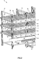
- the distributing installation illustrated in fig.1 is intended for the distribution of printed publications, for example periodical publications.
- the installation 10 provides a picking up area formed by a shelf unit 11.
- the shelf unit 11 has a framework 12 to which a plurality of support planes 13 is fitted arranged according to a series of vertical rows; in the first embodiment the shelf unit 11 has twenty vertical rows of three supporting planes 13 each.
- Each supporting plane 13 corresponds to three virtual pick-up cells and each row of three supporting planes 13 corresponds to a cell module.
- Each supporting plane 13 is provided with small idler rollers 14 arranged in a series of parallel rows; each supporting plane 13 is further tilted downwards to go towards the front face of the shelf unit 11.
- a toothed stop barrier 15 is arranged, where the stacks of publications stop by the force of gravity.
- numeric LED displays 16 are provided that are fitted to plates 17 that are integral with the stop barriers 15.
- the single LEDs can take on various colours, for example red, green and yellow, to provide operators with different information, when necessary.
- a series of lighted push buttons 19 is also fitted, each at a respective cell module, which can assume two different colours, for example green and red, to indicate two different statuses, as will be seen below.
- each conveyor belt 20 is driven independently of the others according to one direction or according to an opposite advancement direction.
- a roller switching means 22 is arranged that is able to route the publications towards the one or other of two further rectilinear roller conveyors.
- the switching means 22 is of known type and is illustrated in detail in fig.6 : it provides a containing structure 23 inside which a series of parallel rows of pairs of driven rollers 24 is arranged.
- Each pair of rollers 24 protrudes from a circular opening 25 of the containing structures 23 and is able to rotate around a first, horizontal axis, to advance the publications; further, each pair of rollers 24 is able to rotate also around a second axis that is vertical, perpendicular to the first axis to move to one or the other of two positions corresponding to the two different aforesaid routing directions.
- Some axes are indicated by a dashed line in fig. 6 .
- the two further rectilinear roller conveyors downstream of the switching means 22 are both indicated with 26, are identical, and are provided with the same number of zones motor-driven and controlled singly.
- sensors are placed for managing the entry, advancement and exit of the packets.
- These sensors can be barrier sensors and are shown by way of example only in fig.7 , where they are indicated with 27.
- the station 29 is clearly visible in fig.7 .
- the station 29 provides two conveyable pallets B alongside one another, on each of which four containers C are arranged that are provided with reclosable lids.
- Each container C is intended to contain the publications packaged for just one customer.
- a container is full, once the lid is closed and an identifying label is affixed, a second container C can be rested thereupon that is of the same type and which is intended for the same customer, and so on up to, for example, four stacked containers C.
- the two pallets B thus house, in an ordered manner, the containers C of eight customers.
- the number of customers present in processing in the station 29 and during the picking up cycle is defined at the start of the distribution cycle.
- the station 29 provides a framework 30 arranged straddling the pallets B and the containers C.
- Eight touchscreen monitors 32 controlled by computer are arranged above the containers C, fitted to the framework 30; four monitors 32 are arranged on the side of an operator and another four are arranged on the opposite side where the other operator operates.
- Each monitor 32 overlooks a respective pair of containers C. Between the monitor 32 that overlook the same pair of containers C, a label printer 33 is present that is fitted to the framework 30, for a total of four printers 33. Each printer 33 is at the disposition of the two operators.
- each sensor 34 is arranged at a respective pair of containers C. These sensors 34 check whether the copies have been placed inside the containers C.
- the camera sensors 34 are 3D reading sensors that enable the volume occupied by the publications in the containers to be evaluated quantitatively.
- the entire installation 10 is managed by a control unit U, illustrated schematically in fig.7 , connected to the numeric displays 16 and to the luminous push buttons 19, further connected to the motors of the conveyor belts 20, of the roller conveyors 21 and 26, and of the roller switching means 22, and to the electronic scales 28, and lastly connected to the barrier sensors 27, to the barcode readers 31, to the monitors 32, to the printers 33, and to the camera sensors 34.
- a control unit U illustrated schematically in fig.7 , connected to the numeric displays 16 and to the luminous push buttons 19, further connected to the motors of the conveyor belts 20, of the roller conveyors 21 and 26, and of the roller switching means 22, and to the electronic scales 28, and lastly connected to the barrier sensors 27, to the barcode readers 31, to the monitors 32, to the printers 33, and to the camera sensors 34.
- the operation of the installation 10 is as follows.
- each operator acts who move along the shelf unit. If there is more than one operator, each operator works on the same pick-up cell unit. All this is communicated, at the start of the work cycle, to the control unit U.
- each supporting plane 13 of the shelf units 11 the copies of the various publications are arranged in an ordered manner in accordance with what is indicted by the control unit U to the operators, for example by monitors that are not illustrated.
- On each supporting plane 13 three stacks of copies of printed publications are arranged, each stack at a numeric display 16.
- Each stack of publications refers to copies of a specific publication that is the same as or different from that of the other stacks arranged on the supporting planes 13 of the shelf units 11.
- the idler rollers 14 of the supporting planes 13 and the tilt of the supporting planes 13 cause the copies to slide against the stop barriers 15, ready to be picked up.
- the conveyor belts 20 start to move.
- the control unit U lights up with a green colour the push button 19 of the first cell module where copies to pick up are present.
- the number of copies to pick up is indicated by the control unit U and the operator removes the copies indicated by the displays 16 and places the copies on one of the conveyor belts 20, stacking, without separating, them.
- the operator can also remove more than one packet of copies until the total indicated by the displays 16 is reached.
- the single packets can also be placed on the conveyor belt 20 separately or superimposed, but not in single copies.
- the control unit U presents to the operator separately the number of entire packs to be removed and the number of loose copies, with a sequence of numbers of the type "1--3" to indicate that an entire pack and three loose copies should be picked up.
- the numbers that indicate the entire packs and the number that indicate the loose copies can be of a different colour.
- the operator can also place a new packet of copies of a different publication on a packet of copies already present on the conveyor belt and belonging to a different publication, provided that it is rotated by 90° in order to make it visible to subsequent operators; in this manner it can continue work without stopping.
- the relative motion between the operator and the conveyor belt 20 helps the operator to insert the packets next to one another separately, to enable the control unit U to manage the accumulation of the packets on the subsequent zoned driven roller conveyor 26.
- the operator advances in the direction opposite to the motion of the conveyor belt 20, thus from right to left in fig. 1 until the publications are picked up from all the cells of a cell module.
- the operation that has just been disclosed represents a pick-up cycle that may refer to a number of customers that is variable from one to eight, as defined preferably at the start of the work cycle.
- the control unit U determines on a case by case basis the number of customers comprised in that work cycle, up to the maximum permitted by the geometry of the installation, i.e. eight in the embodiment, in complete autonomy.
- the pick-up cycle is terminated and the operator will press the red push button to inform the control unit U of the end of the pick-up cycle.
- the control unit U will again light up the green push button 19 to indicate the most favourable starting point for the next pick-up cycle.
- the operator will go as far as the cell module with the lighted green push button and during this path will replenish the cells that are empty or have few copies with publications.
- the operator will press the green switch of the subsequent pick-up cycle start module; only then will the displays 16 relating to the new work cycle be switched on.
- the packets of copies placed on the conveyor belts 20 are dragged forwards until they reach the roller conveyor 21 and then, through the roller switching means 22, one of the two roller conveyors 26.
- Routing the packets inside the roller conveyor 21 to one or the other of the subsequent roller conveyors 26 by the roller switching means 22 is decided between one pick-up cycle and the next.
- the barrier sensors 27 arranged along the roller conveyors 21 and 26 enable the control unit U to detect the transit of the packets on the roller conveyors 21 and 26 and to stop or start up the roller conveyors 21 and 26, depending on the needs of the process of advancement of the packets in order to maintain the packets in an ordered position along the path.
- the change of direction of the roller switching means 21 will be activated by the control unit U at the end of a work cycle of the operator of the shelf unit 11, i.e. when the operator has ended picking up for a group of customers, and after the correct time has elapsed from the end of the preceding pick-up cycle (i.e. when the cycle end red push button is pressed) to enable the transit of the last packet beyond the roller switching means 21.
- the control unit U will also control the possible concomitant stop of the conveyor belt 20 for reasons connected to the process.
- Each of the packets conveyed by one of the two roller conveyors 26 reaches the scale 28, where it is weighed and picked up by a station 29 operator.
- the operator has the barcode of the publication read by one of the readers 31 and immediately on the monitors 32 the quantities are displayed to be inserted into the containers C of each customer.
- Each monitor 32 shows the data in a manner corresponding geometrically to the arrangement of the containers C to which they refer.
- the control unit U can be configured for actuating two different work modes in the station 29:
- the label will show, at least, the customer code and corresponding barcode, personal data of the sales outlet, distribution data, consecutive number of the container C and possibly the publications contained in the container C.
- both operators of the station 29 are present (the station 29 can also operate with just one operator, if declared at the start of the pick-up cycle), they work on the same customer containers and enter the copies indicated by the respective monitors 32 thereof belonging to different publications (mode a) or to the same publication (tandem operation, mode b).
- each operator will operate "in turns” i.e. will insert in a stroke, going from the scale 28 to the last container C, the copies relating to the containers C nearest the operator, whereas in the return stroke to the scales 28 the operator will insert the copies relating to the containers C place further away.
- the control unit U will check the congruence between the weight detected by the scale 28 and copies provided for that packet, so as to perform a form of automatic check.
- the possible incongruence will be indicated on the monitor 32, and the operator will add the missing copy or copies or will remove the excess copy or copies; alternatively the error can be left, correcting the amounts displayed on the monitor 32 to be distributed in the containers C and recording this error by the control unit U in a processing report assigned to the operators, the customer, the publication and other interested parties.
- a form of manual control can be provided, in which the copies are counted in two steps, by different operators: the one checks the work of the other.
- the operator of the shelf unit 11 counts the total copies provided for that pick-up cycle; the operator of the station 29 counts the copies of every single copy to be packaged for that cycle, as will be indicated to the operator by the monitors 32.
- the amount must be the same as the total: otherwise, the operator of the terminal station 29 will report the difference detected by pressing relevant keys of the monitor 32.
- the detected errors will be recorded by the control unit U, which will then supply a report on the behaviour of the operators. In this operating mode, the presence of the electronic scale 28 becomes superfluous.
- the operator at the shelf unit 11 at the end of a batch of customers corresponding to a homogeneous dispatch group, can process entire publication packs relating to that dispatch group: the entire publication packs are the publication packs sent by the publishers that have to be delivered complete to a given customer. For the convenience of the person who will actually deliver to the customers and to avoid delivery errors, these packs must be labelled with the indication of the recipient customer and are placed on one of the two pallets B on which the containers C of that already closed delivery group rest, or on a separate pallet B if necessary.
- the operator of the shelf unit 11 will pick up the entire packs, as will be indicated by the displays 16 of the cells of the shelf unit 11 (it will be the control unit U that will "remember" to perform this work cycle).
- the packs placed on the conveyor belt 20 will be conveyed to one of the stations 29, as already seen, and will be taken by the operators of this station 29.
- the operators will pick up the packs one at a time and after reading the barcode, the control unit U will print the labels customized for the recipient customer from one of the printers 33 of the station 29. Having four printers 33 available, the control unit U will assign one printer 33 to one operator and another to the other.
- the corresponding pallet B must be replaced. On the monitors 32 of the station 29 the appropriate messages for warning the operators will appear.
- the disclosed and illustrated installation 10 has many advantages.
- the tilted planes 13 with the rollers 14 promote loading and the correct arrangement of the copies.
- this solution would enable a second operator to be inserted to perform a work cycle that starts immediately after the end of the work cycle performed by the preceding operator, but intended for a different packaging terminal station, increasing noticeably the productivity of the installation.
- the documents delivered to the sales outlets can be exact with respect to what is present in the containers C: in fact, possible errors of the operators detected by the double count of the copies picked up and placed in the containers C (for example whether the operator of the shelf unit 11 has picked up less than requested) can be transformed into a variation of the delivered quantity; the monitoring of the placing in container C, conducted with the help of the camera sensors 34 present in the station 29 enables the placing of incorrect copies in containers C and non-placing of copies in provided containers C to be eliminated.
- the sequence of the containers C to be filled for the sales outlets can be chosen in the most suitable manner for the subsequent delivery process; for example, the containers C relating to the furthest sales outlets can be filled and dispatched first whereas the rest of the containers C will be filled and dispatched subsequently.
- This system enables the time of delivery of the products to the customers to be anticipated.
- the containers C are filled and are positioned directly on the pallet B used for the dispatch, relating to a group of sales outlets to be served; there is thus no process of selecting and loading containers, or the corresponding technology.
- the simplification is very significant in terms of effort saved and technology neither purchased nor maintained.
- the installation can process with just a few operators, in the embodiment with three operators, who can be reduced to two with obviously an increase in processing time.
- both the stations 29 enables reduced processing times to be obtained.
- the shelf unit 11 will be deemed to be divided into two equal parts, arranging the products to be distributed over the two halves of the shelf unit 11 thus obtained.
- One of the conveyor belts 20 will act as in the preceding description, and the other conveyor belt 20 will act in the opposite direction so as to direct the packets picked up at the other end from the preceding conveyor belt 20.
- the same components 21-34, B, C seen in the embodiment it is possible to duplicate the productivity of the installation, thus having four outlet points of the containers C to be directed to the newsagents.
- the shelf unit 11 is reused for uses that are very different from one another. Everything would nevertheless occur under the control of the control unit U.
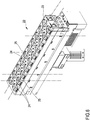
- the distributing installation illustrated in fig.8 is also intended for distributing printed publications and has many similarities with the distributing installation 10 disclosed above.
- the installation 50 also provides a picking up area formed by a shelf unit 51.
- the shelf unit 51 has a framework 52 to which a plurality of supporting planes 53 is fitted arranged according to a series of vertical rows; in the present embodiment the shelf unit 51 has twenty-three vertical rows of three supporting planes 53 each.
- Each lower or upper supporting plane 53 corresponds to three virtual pick-up cells, whereas each intermediate supporting plane 53 between the lower and the upper supporting plane corresponds to two virtual pick-up cells.
- Each row of three supporting planes 53 corresponds to a cell module.
- Each supporting plane 53 is provided with smaller idling rollers 54 arranged in a series of parallel rows; each supporting plane 53 is further tilted downwards towards the front face of the shelf unit 51.
- each tilted supporting plane 53 On the front face of the shelf unit 51 a stop barrier 55 is arranged, where the stacks of publications will stop through the force of gravity.
- a series of touchscreen monitors 56 is provided that are fitted to plates 57 that are integral with the stop barriers 55.
- the monitors 56 replace the LEDs 16 and the lighted push buttons 19 seen in the installation 10, performing the same function.
- Each monitor 56 is arranged between the two virtual pick-up cells of a respective intermediate supporting plane 53.
- each conveyor belt 58 is thus provided for a total of twenty-three conveyor belts 58.
- Such conveyor belts 58 are aligned and each conveyor belt 58 is driven independently with respect to the others according to one direction or according to an opposite advancement direction, as for the conveyor belts 20 of the installation 10.
- respective barrier sensors are arranged that are not illustrated that are identical to the barrier sensors 27 of the installation 10.
- barcode readers are fitted that are not illustrated that are identical to the barcode 31 readers of the installation 10.
- a further packaging end station 62 is provided that is identical to the packaging station 29 of the installation 10.
- terminal station 62 groups of containers C are provided, as for the distributing installation 10, on which some touchscreen monitors 63 are provided, of larger dimensions but fewer in number than the monitors 32 of the installation 10.
- Label printers are also provided that are not illustrated that are identical to the label printers 33 of the installation 10.
- the installation 50 is managed by a non-illustrated control unit, connected to the components seen above.
- the operation of the installation 50 is as follows.
- the conveyor belts 58 are stationary.
- the control unit lights up with a green colour a square of the monitor 56 of the first cell of the first cell module where the copies to be picked up are present.
- the control unit On the lighted square the number of copies to pick up is indicated by the control unit and the operator picks up the copies placed in the cell corresponding geometrically to that square and places the copies on the conveyor belt 58 of the module, which is at this moment stationary, stacked without separating.
- the operator can also pick up more than one packet of copies until the total indicated by the square of the lighted monitor 56 is reached.
- the single packets can also be placed on the conveyor belt 58 separately or superimposed, but not as single copies, and inside the conveyor belt 58 of the module being processed.
- control unit presents to the operator separately the number of entire packs to be picked up and the number of loose copies, each shown in a suitable field (copies or entire packs) of the monitor 56.
- a suitable field copies or entire packs
- the fields that contain the entire packs and the numbers that indicate the loose copies can be a different colour.
- the operator will place a new packet of copies of a different publication in the space available inside the conveyor belt 58. If it is convenient for him to superimpose the packet on another packet already present on the conveyor belt and belonging to a different publication, the operator will turn the packet 90° in order to make the packet visible to subsequent operators.
- a platform can also be provided at the shoulders of the operator with a mass circulation publication the pick-up data of which will be displayed in the central square of the monitor 56.
- the operator will press a conveyor belt advancement button, which is displayed in the monitor 56.
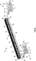
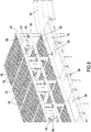
- the conveyor belt 58 will move to the right (with reference to figures 8 , 9 , 10 ) and the operator will move to the next module placed on the operator's left.
- Fig.9 shows the start of the right side of the shelf unit: the conveyor belt 58 will start to move to the right, whilst the operator, at the end of picking up on the first module, will pass to the left module, where the corresponding conveyor belt 58 is stationary.
- the operator advances in the opposite direction to the motion of the conveyor belt 58, thus from right to left in fig. 9 , until the publications have been picked up from all the cells of all the modules, repeating the work cycle disclosed.
- the operation that has just been disclosed represents a pick-up cycle that may refer to a number of customers that vary from one to eight, as preferably defined at the start of the work cycle.
- the control unit determines on a case-by-case basis the number of customers comprised in that work cycle, up to the maximum permitted by the geometry of the installation, namely eight in the embodiment, in complete autonomy.
- the pick-up cycle Upon reaching the end of the shelf unit 51, or reaching the last module on which a luminous lighted red square of a monitor 56 is present, the pick-up cycle is terminated and the operator will press the red push button on the monitor 56 to alert the control unit to the end of the pick-up cycle.
- the control unit will again light up a square of green colour of a monitor 56 to indicate the most favourable starting point for the next pick-up cycle.
- the operator will go, from left to right, as far as the cell module with the lighted green square and during this path can take care of refilling with publications the empty cells or the cells with few copies.
- the operator After reaching the aforesaid cell module, the operator will press the green switch of the module to start the following pick-up cycle; only then will the data light up relating to the new work cycle in the monitor 56 of the module.
- the packets of copies placed on the conveyor belts 58 (which for the sake of convenience will be called copy trolleys) are all dragged together to the right until they reach the line of conveyor belts 59,60,61.
- This line of conveyor belts will receive a copy trolley corresponding to what is contained in a conveyor belt 58.
- This trolley will enter in the line of conveyor belts 59 and 60; once the trolley has entered, the conveyor belts will stop so as to fill it with the subsequent wagons arriving, keeping each trolley separate from the subsequent and preceding trolley.
- the barrier sensors will enable the wagons to advance inside the line of conveyor belts 59, 60, 61.
- the final conveyor belt 61 has a linear dimension equal to that of the conveyor belt 58 (as much as a trolley), just as the conveyor belt 60 has an extent that is the same as a complete multiple of a conveyor belt 58; whereas the curved conveyor belt 59 is commensurate with the extent of just one trolley. This means that the advancement of the packets on the conveyor belt 58 will always be the same by unit as the extent of the trolley.
- the barrier sensors enable the control unit to detect the transit of the trolleys or stop or start the conveyor belts 59,60,61, depending on the needs of the packet advancement process, in order to maintain the trolleys in an ordered position, and thus the packets contained therein, along the path.
- the control system will also take account of the geometric length of each trolley, controlling the advancement of the surface of the conveyor belts 58,59,60,61 (with an encoder or something else).
- the conveyor belt 61 will take the publications trolley inside the packaging station 62.
- the system will move a new trolley forward from the conveyor belts 59 and 60 to the conveyor belt 61.
- the second line of conveyor belts 59,60,61 and the second packaging terminal station 62, to the left in the figures, will be fed by the operator during the return stroke from the left end of the shelf unit 51 to the right end.
- all the conveyor belts 58 will be commanded one by one to rotate in the opposite direction to the preceding situation, thus directing the trolleys of picked up packets to the left terminal station 62.
- the operation of the system in this second stroke from left to right, is similar to that of the stroke in the advancement direction from right to left.
- the distribution installation 50 has the same advantages disclosed for the distribution installation 10 disclosed above and in addition has greater productivity with respect to the installation 10.
- the number and the arrangement of the shelf units can vary according to need.
- roller conveyors 21,26, of the roller switching means 22, and of the terminal packaging stations can vary according to need.
- the roller conveyors 26 can also be replaced with cloth conveyor belts provided with barrier sensors at the ends to detect the presence of the packets.
- the roller switching means 22 can be replaced with a conveyor belt balancing on a horizontal axis, lifted or lowered at the ends by means of a suitable actuator, to direct the packets to one or another of several conveyor belts superimposed on parallel planes, obtaining the same separation result as the flow of packets to one or the other terminal packaging station.
- This conveyor solution can be preferable for example in the case of a particular type of product to be conveyed that could generate problems if conveyed on rollers.
- the number and the arrangement of the electronic scales can vary. As seen above, the electronic scales can also not be provided.
- the sensors arranged along the motor-driven roller conveyors can be of any type.
- the system for recognizing the copy with a barcode can be made with a laser ray device or image recognition device.
- Electronic paper (i-paper) labels can also be used to identify the containers C.
- the containers can be devoid of lids.
- the containers can be replaced by any type of container that is suitable for the purpose.
- a different arrangement could enable a printer to be used for each operator.
- Also more than two terminal packaging stations can be provided.
- the disclosed and illustrated installations are intended for distributing printed publications.
Applications Claiming Priority (1)
| Application Number | Priority Date | Filing Date | Title |
|---|---|---|---|
| IT102018000006516A IT201800006516A1 (it) | 2018-06-20 | 2018-06-20 | Impianto di distribuzione di oggetti in genere ed in particolare di pubblicazioni a stampa |
Publications (1)
| Publication Number | Publication Date |
|---|---|
| EP3584198A1 true EP3584198A1 (fr) | 2019-12-25 |
Family
ID=63684246
Family Applications (1)
| Application Number | Title | Priority Date | Filing Date |
|---|---|---|---|
| EP19181213.0A Withdrawn EP3584198A1 (fr) | 2018-06-20 | 2019-06-19 | Système de distribution pour la distribution d'objects, en particulier d'articles de presse |
Country Status (2)
| Country | Link |
|---|---|
| EP (1) | EP3584198A1 (fr) |
| IT (1) | IT201800006516A1 (fr) |
Citations (7)
| Publication number | Priority date | Publication date | Assignee | Title |
|---|---|---|---|---|
| JPS59217504A (ja) * | 1983-05-20 | 1984-12-07 | Toyo Kanetsu Kk | 物流システムにおけるピッキング指示装置 |
| JPH01260485A (ja) * | 1988-04-12 | 1989-10-17 | Daifuku Co Ltd | 表示装置 |
| JP2009062142A (ja) * | 2007-09-06 | 2009-03-26 | Hitachi Plant Technologies Ltd | 仕分けシステム及び仕分け方法 |
| JP4993580B2 (ja) * | 2007-01-31 | 2012-08-08 | オークラ輸送機株式会社 | ピッキングシステム |
| JP2014166919A (ja) * | 2014-05-13 | 2014-09-11 | Okura Yusoki Co Ltd | ピッキング設備 |
| EP3088340A1 (fr) | 2015-04-29 | 2016-11-02 | Stefan Klotzner | Système de collection automatique de magazines et de journaux pour chaque marchand de journaux |
| EP3138635A1 (fr) | 2015-09-02 | 2017-03-08 | Stefan Klotzner | Système de distribution, emballage automatique et retour de produits de publication |
-
2018
- 2018-06-20 IT IT102018000006516A patent/IT201800006516A1/it unknown
-
2019
- 2019-06-19 EP EP19181213.0A patent/EP3584198A1/fr not_active Withdrawn
Patent Citations (7)
| Publication number | Priority date | Publication date | Assignee | Title |
|---|---|---|---|---|
| JPS59217504A (ja) * | 1983-05-20 | 1984-12-07 | Toyo Kanetsu Kk | 物流システムにおけるピッキング指示装置 |
| JPH01260485A (ja) * | 1988-04-12 | 1989-10-17 | Daifuku Co Ltd | 表示装置 |
| JP4993580B2 (ja) * | 2007-01-31 | 2012-08-08 | オークラ輸送機株式会社 | ピッキングシステム |
| JP2009062142A (ja) * | 2007-09-06 | 2009-03-26 | Hitachi Plant Technologies Ltd | 仕分けシステム及び仕分け方法 |
| JP2014166919A (ja) * | 2014-05-13 | 2014-09-11 | Okura Yusoki Co Ltd | ピッキング設備 |
| EP3088340A1 (fr) | 2015-04-29 | 2016-11-02 | Stefan Klotzner | Système de collection automatique de magazines et de journaux pour chaque marchand de journaux |
| EP3138635A1 (fr) | 2015-09-02 | 2017-03-08 | Stefan Klotzner | Système de distribution, emballage automatique et retour de produits de publication |
Also Published As
| Publication number | Publication date |
|---|---|
| IT201800006516A1 (it) | 2019-12-20 |
Similar Documents
| Publication | Publication Date | Title |
|---|---|---|
| US11912506B2 (en) | Modular product dispensing and verification system and method | |
| EP0798239B1 (fr) | System de sélection de produits et son procédé | |
| KR101537574B1 (ko) | 물품 수용 시스템, 물품 수용 반출 방법 | |
| JP6096804B2 (ja) | 容器をスタックするための材料取扱設備およびスタッカ器具 | |
| US9199792B2 (en) | Sorting and distributing system | |
| KR102080036B1 (ko) | 약제 지급기 및 관련 방법에 대한 포장 시스템 | |
| US4507739A (en) | Sorter system for postal matter | |
| US8755931B2 (en) | Pick-to-window | |
| US20120150340A1 (en) | Storage and commissioning system and method for operating the same in batch mode | |
| KR20090118918A (ko) | 아이템 소팅 방법 및 아이템 소팅 장치 | |
| CN108367863A (zh) | 分拣系统 | |
| CN108463419A (zh) | 分拣系统 | |
| CN105188638A (zh) | 药剂配药系统 | |
| JP2004131239A (ja) | 仕分け装置 | |
| JP2020117337A (ja) | パレット交換システム | |
| EP3584198A1 (fr) | Système de distribution pour la distribution d'objects, en particulier d'articles de presse | |
| US6606842B2 (en) | Apparatus for dispensing change | |
| JP2016060626A (ja) | 物品保管仕分け装置 | |
| US6598376B2 (en) | Apparatus for dispensing change | |
| JP2002225811A (ja) | 卵自動包装システム | |
| JP3937782B2 (ja) | ピッキング設備 | |
| JP3591903B2 (ja) | 出版物のピッキング計量検品システム | |
| JP2927740B2 (ja) | 物品のピッキング方法 | |
| JP6107501B2 (ja) | 仕分け設備 | |
| JPH07110684B2 (ja) | 物流倉庫における出庫指示装置 |
Legal Events
| Date | Code | Title | Description |
|---|---|---|---|
| PUAI | Public reference made under article 153(3) epc to a published international application that has entered the european phase |
Free format text: ORIGINAL CODE: 0009012 |
|
| STAA | Information on the status of an ep patent application or granted ep patent |
Free format text: STATUS: THE APPLICATION HAS BEEN PUBLISHED |
|
| AK | Designated contracting states |
Kind code of ref document: A1 Designated state(s): AL AT BE BG CH CY CZ DE DK EE ES FI FR GB GR HR HU IE IS IT LI LT LU LV MC MK MT NL NO PL PT RO RS SE SI SK SM TR |
|
| AX | Request for extension of the european patent |
Extension state: BA ME |
|
| STAA | Information on the status of an ep patent application or granted ep patent |
Free format text: STATUS: REQUEST FOR EXAMINATION WAS MADE |
|
| 17P | Request for examination filed |
Effective date: 20200625 |
|
| RBV | Designated contracting states (corrected) |
Designated state(s): AL AT BE BG CH CY CZ DE DK EE ES FI FR GB GR HR HU IE IS IT LI LT LU LV MC MK MT NL NO PL PT RO RS SE SI SK SM TR |
|
| GRAP | Despatch of communication of intention to grant a patent |
Free format text: ORIGINAL CODE: EPIDOSNIGR1 |
|
| STAA | Information on the status of an ep patent application or granted ep patent |
Free format text: STATUS: GRANT OF PATENT IS INTENDED |
|
| RIC1 | Information provided on ipc code assigned before grant |
Ipc: B07C 7/00 20060101ALI20211101BHEP Ipc: B07C 7/02 20060101ALI20211101BHEP Ipc: B65G 1/137 20060101AFI20211101BHEP |
|
| INTG | Intention to grant announced |
Effective date: 20211207 |
|
| STAA | Information on the status of an ep patent application or granted ep patent |
Free format text: STATUS: THE APPLICATION IS DEEMED TO BE WITHDRAWN |
|
| 18D | Application deemed to be withdrawn |
Effective date: 20220420 |