EP3584121B1 - Gehäuse, elektrischer anschlusskasten und kabelbaum - Google Patents
Gehäuse, elektrischer anschlusskasten und kabelbaum Download PDFInfo
- Publication number
- EP3584121B1 EP3584121B1 EP19180728.8A EP19180728A EP3584121B1 EP 3584121 B1 EP3584121 B1 EP 3584121B1 EP 19180728 A EP19180728 A EP 19180728A EP 3584121 B1 EP3584121 B1 EP 3584121B1
- Authority
- EP
- European Patent Office
- Prior art keywords
- packing
- housing
- case
- cover
- groove
- Prior art date
- Legal status (The legal status is an assumption and is not a legal conclusion. Google has not performed a legal analysis and makes no representation as to the accuracy of the status listed.)
- Active
Links
Images


Classifications
-
- H—ELECTRICITY
- H01—ELECTRIC ELEMENTS
- H01R—ELECTRICALLY-CONDUCTIVE CONNECTIONS; STRUCTURAL ASSOCIATIONS OF A PLURALITY OF MUTUALLY-INSULATED ELECTRICAL CONNECTING ELEMENTS; COUPLING DEVICES; CURRENT COLLECTORS
- H01R13/00—Details of coupling devices of the kinds covered by groups H01R12/70 or H01R24/00 - H01R33/00
- H01R13/46—Bases; Cases
- H01R13/52—Dustproof, splashproof, drip-proof, waterproof, or flameproof cases
- H01R13/5202—Sealing means between parts of housing or between housing part and a wall, e.g. sealing rings
-
- B—PERFORMING OPERATIONS; TRANSPORTING
- B60—VEHICLES IN GENERAL
- B60R—VEHICLES, VEHICLE FITTINGS, OR VEHICLE PARTS, NOT OTHERWISE PROVIDED FOR
- B60R16/00—Electric or fluid circuits specially adapted for vehicles and not otherwise provided for; Arrangement of elements of electric or fluid circuits specially adapted for vehicles and not otherwise provided for
- B60R16/02—Electric or fluid circuits specially adapted for vehicles and not otherwise provided for; Arrangement of elements of electric or fluid circuits specially adapted for vehicles and not otherwise provided for electric constitutive elements
- B60R16/0207—Wire harnesses
-
- B—PERFORMING OPERATIONS; TRANSPORTING
- B60—VEHICLES IN GENERAL
- B60R—VEHICLES, VEHICLE FITTINGS, OR VEHICLE PARTS, NOT OTHERWISE PROVIDED FOR
- B60R16/00—Electric or fluid circuits specially adapted for vehicles and not otherwise provided for; Arrangement of elements of electric or fluid circuits specially adapted for vehicles and not otherwise provided for
- B60R16/02—Electric or fluid circuits specially adapted for vehicles and not otherwise provided for; Arrangement of elements of electric or fluid circuits specially adapted for vehicles and not otherwise provided for electric constitutive elements
- B60R16/023—Electric or fluid circuits specially adapted for vehicles and not otherwise provided for; Arrangement of elements of electric or fluid circuits specially adapted for vehicles and not otherwise provided for electric constitutive elements for transmission of signals between vehicle parts or subsystems
- B60R16/0238—Electrical distribution centers
-
- B—PERFORMING OPERATIONS; TRANSPORTING
- B60—VEHICLES IN GENERAL
- B60R—VEHICLES, VEHICLE FITTINGS, OR VEHICLE PARTS, NOT OTHERWISE PROVIDED FOR
- B60R16/00—Electric or fluid circuits specially adapted for vehicles and not otherwise provided for; Arrangement of elements of electric or fluid circuits specially adapted for vehicles and not otherwise provided for
- B60R16/02—Electric or fluid circuits specially adapted for vehicles and not otherwise provided for; Arrangement of elements of electric or fluid circuits specially adapted for vehicles and not otherwise provided for electric constitutive elements
- B60R16/023—Electric or fluid circuits specially adapted for vehicles and not otherwise provided for; Arrangement of elements of electric or fluid circuits specially adapted for vehicles and not otherwise provided for electric constitutive elements for transmission of signals between vehicle parts or subsystems
- B60R16/0239—Electronic boxes
-
- H—ELECTRICITY
- H01—ELECTRIC ELEMENTS
- H01R—ELECTRICALLY-CONDUCTIVE CONNECTIONS; STRUCTURAL ASSOCIATIONS OF A PLURALITY OF MUTUALLY-INSULATED ELECTRICAL CONNECTING ELEMENTS; COUPLING DEVICES; CURRENT COLLECTORS
- H01R13/00—Details of coupling devices of the kinds covered by groups H01R12/70 or H01R24/00 - H01R33/00
- H01R13/66—Structural association with built-in electrical component
-
- H—ELECTRICITY
- H02—GENERATION; CONVERSION OR DISTRIBUTION OF ELECTRIC POWER
- H02G—INSTALLATION OF ELECTRIC CABLES OR LINES, OR OF COMBINED OPTICAL AND ELECTRIC CABLES OR LINES
- H02G3/00—Installations of electric cables or lines or protective tubing therefor in or on buildings, equivalent structures or vehicles
- H02G3/02—Details
- H02G3/08—Distribution boxes; Connection or junction boxes
- H02G3/081—Bases, casings or covers
-
- H—ELECTRICITY
- H02—GENERATION; CONVERSION OR DISTRIBUTION OF ELECTRIC POWER
- H02G—INSTALLATION OF ELECTRIC CABLES OR LINES, OR OF COMBINED OPTICAL AND ELECTRIC CABLES OR LINES
- H02G3/00—Installations of electric cables or lines or protective tubing therefor in or on buildings, equivalent structures or vehicles
- H02G3/02—Details
- H02G3/08—Distribution boxes; Connection or junction boxes
- H02G3/088—Dustproof, splashproof, drip-proof, waterproof, or flameproof casings or inlets
-
- H—ELECTRICITY
- H05—ELECTRIC TECHNIQUES NOT OTHERWISE PROVIDED FOR
- H05K—PRINTED CIRCUITS; CASINGS OR CONSTRUCTIONAL DETAILS OF ELECTRIC APPARATUS; MANUFACTURE OF ASSEMBLAGES OF ELECTRICAL COMPONENTS
- H05K5/00—Casings, cabinets or drawers for electric apparatus
- H05K5/06—Hermetically-sealed casings
- H05K5/061—Hermetically-sealed casings sealed by a gasket held between a removable cover and a body, e.g. O-ring, packing
-
- H—ELECTRICITY
- H05—ELECTRIC TECHNIQUES NOT OTHERWISE PROVIDED FOR
- H05K—PRINTED CIRCUITS; CASINGS OR CONSTRUCTIONAL DETAILS OF ELECTRIC APPARATUS; MANUFACTURE OF ASSEMBLAGES OF ELECTRICAL COMPONENTS
- H05K5/00—Casings, cabinets or drawers for electric apparatus
- H05K5/06—Hermetically-sealed casings
- H05K5/063—Hermetically-sealed casings sealed by a labyrinth structure provided at the joining parts
Definitions
- the present invention relates to a housing that includes a case, a cover and a packing, an electric connection box that includes the housing, and a wire harness that includes the electric connection box at an end portion thereof.
- DE 93 21 190 U1 discloses a housing comprising a case that has a first surface having an opening; and a cover that covers the opening and has a second surface that is in surface contact with the first surface.
- This document also shows a packing groove to which the packing is attached.
- JP-A-2003-101256 discloses two different waterproof structures of a housing that includes: a case having an opening, and a cover that covers the opening of the case.
- a packing groove is formed around the opening of the case, and an annular first packing is attached to the packing groove. According to this structure, when the cover covers the case, the first packing is compressed, and at this time, the first packing is in close contact with both the case and the cover to prevent infiltration of water.
- a second packing is attached to an outer side of the first packing.
- the second packing is also compressed and in close contact with the case and the cover. Accordingly, a double waterproof structure of the first packing and the second packing can be obtained, and infiltration of water can be prevented more reliably.
- an outer extension portion is formed on an outer periphery of the case, and the case has a stepped shape so that the outer extension portion is located below an opening position of the case in a vertical direction.
- the second packing is attached to the outer extension portion.
- an eaves portion is formed on the cover in accordance with a position of the outer extension portion of the case.
- the eaves portion is formed in a stepped shape with respect to a main body portion of the cover in accordance with a step of the case.
- the eaves portion is formed as a portion that compresses the second packing.
- the waterproof structure described above when water as a subject of waterproofing includes, for example, salt, the following technical problems are exemplified. That is, according to the first waterproof structure, although water (salt water) is blocked by a packing, during repeated contact and drying of water, crystallization of salt proceeds and deterioration of the packing occurs, which causes a technical problem that a waterproof function (an anticorrosion function against salt) is deteriorated. In addition, since the second waterproof structure has a stepped shape and double packings, there is a technical problem that the housing is complicated, increased in size, and the number of components is increased.
- the invention has been made in view of the above circumstances, and an object thereof is to provide a housing, an electric connection box and a wire harness which can be simplified and reduced in size while ensuring a waterproof and anticorrosion function.
- a first aspect of the invention provides a housing that includes a case that has a first surface having an opening; a cover that covers the opening and has a second surface that is in surface contact with the first surface; an annular packing that is disposed on an outer side of the opening, in which one of the first surface and the second surface has a packing groove to which the packing is attached, and a groove portion that is disposed on an outer side of the packing groove and formed on a same plane as the packing groove.
- the groove portion is formed on the outer side of the packing groove, water that includes, for example, salt can be stored in the groove portion before reaching the packing, and as a result, crystallization of the salt can occur in the groove portion rather than in the packing. Therefore, deterioration of the packing is prevented and a waterproof function (an anticorrosion function against salt) can be maintained. Further, even if water that includes salt passes beyond the groove portion and reaches the packing, and the crystallization of the salt occurs in the packing, an occurrence of the crystallization can be delayed due to presence of the groove portion, and the deterioration of the packing which may impair the waterproof function (the anticorrosion function against salt) can be prevented.
- the housing according to the first aspect can be provided with a waterproof structure (an anticorrosion structure) effective as a permanent measure.
- a waterproof structure an anticorrosion structure
- the housing can be simplified and reduced in size as compared with the structure described in the background art.
- a sufficient waterproof and anticorrosion function can be secured with only one packing, an increase in the number of components can be prevented, and assembly of the housing can be facilitated.
- a second aspect of the invention provides the housing according to the first aspect described above which further includes a plurality of fastening members that fasten the case and the cover, in which each of the case and the cover has a plurality of fastening portions which are formed at positions on an outer side of the packing and the packing groove and to which the plurality of fastening members are fastened, respectively, and the groove portion is disposed at a position at which the plurality of fastening portions are connected.
- the housing since the groove portion is formed at the position at which the plurality of fastening portions are connected, the housing does not increase in size due to the groove portion. Therefore, it is possible to contribute to reduction in size of the housing.
- a third aspect of the invention provides the housing according to the first aspect which further includes a plurality of fastening members that fasten the case and the cover, in which each of the case and the cover has a plurality of fastening portions which are formed at positions on an outer side of the packing and the packing groove and to which the plurality of fastening members are fastened, respectively, and the groove portion is disposed at a position on an inner side of the plurality of fastening portions.
- the housing since the groove portion is formed at the position on the inner side of the plurality of fastening portions, the housing does not increase in size due to the groove portion. Therefore, it is possible to contribute to reduction in size of the housing.
- a fourth aspect of the invention provides the housing according to the first aspect which further includes a plurality of fastening members that fasten the case and the cover, in which each of the case and the cover has a plurality of fastening portions which are formed at positions on an outer side of the packing and the packing groove to which the plurality of fastening members are fastened, and the groove portion is disposed at a position on an outer side of and in a vicinity of the plurality of fastening portions.
- the housing since the groove portion is formed at the position on the outer side of and in the vicinity of the plurality of fastening portions, the housing does not increase in size due to the groove portion. Therefore, it is possible to contribute to reduction in size of the housing.
- a fifth aspect of the invention provides the housing according to one of the first aspect to the fourth aspect, in which a bottom surface of the groove portion has a recessed cross-sectional shape.
- the groove portion has the bottom surface with the recessed cross-sectional shape, more water that includes, for example, salt can be stored.
- a sixth aspect of the invention provides the housing according to one of the first aspect to the fourth aspect, in which a bottom portion of the groove portion has a through hole that communicates with an outside of the housing.
- the groove portion has the through hole, water that includes, for example, salt can be drained to the outside of the housing via the through hole. Therefore, since the water can be drained to the outside of the housing, it is possible to contribute to prevention of the deterioration of the packing and to maintain the waterproof function (the anticorrosion function against salt).
- a seventh aspect of the invention provides the housing according to one of the first aspect to the fourth aspect, in which another of the first surface and the second surface has a protruding portion configured to be inserted into the groove portion with a gap therebetween.
- the protruding portion configured to be inserted into the groove portion with the gap therebetween is formed, it is possible to complicate an infiltration path of water that includes, for example, salt and to make it difficult to reach the packing.
- An eighth aspect of the invention provides an electric connection box that includes the housing according to one of the first aspect to the seventh aspect and a plurality of electronic components that are housed in the housing.
- an electric connection box with a high waterproof function an anticorrosion function
- a ninth aspect of the invention provides a wire harness that includes a wiring portion that is installed in an automobile and an end portion that includes the electric connection box according to the eighth aspect.
- a wire harness that includes an electric connection box with a high waterproof function (an anticorrosion function).
- the aspects of the invention achieve an effect that a housing, an electric connection box, and a wire harness, which can be simplified and reduced in size while ensuring a waterproof and anticorrosion function, can be provided.
- an electric connection box that is provided at an end of a wire harness includes a housing and a plurality of electronic components that are housed in the housing.
- the housing includes a case having an opening, a cover that covers the opening, an annular packing that is disposed on an outer side of the opening, and a plurality of fastening members that fasten the case and the cover.
- the case has a first surface having an opening
- the cover has a second surface that is in surface contact with the first surface.
- One of the first surface and the second surface has a packing groove to which the packing is attached and a groove portion that is disposed on an outer side of the packing groove and formed on a same plane as the packing groove.
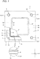
- FIG. 1 is a plan view showing a first example of a housing, a groove and a cover according to an embodiment of the invention.
- FIG. 2 is a cross-sectional view taken along a line A-A in FIG. 1 and
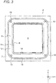
- FIG. 3 is a plan view of a case in FIG. 1 .
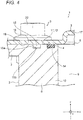
- FIG. 4 is a cross-sectional view of the housing showing a second example of the groove portion
- FIG. 5 is a plan view of a case in FIG. 4
- FIG. 6 is a cross-sectional view of the housing showing a third example of the groove portion
- FIG. 7 is a plan view of a case in FIG. 6 , FIG. 8 and FIG.
- FIG. 9 are cross-sectional views of the housing showing a fourth example and a fifth example of the groove portion, respectively,
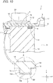
- FIG. 10 is a cross-sectional view of the housing showing a second example of the cover, and
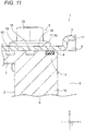
- FIG. 11 is a cross-sectional view of the housing showing a sixth example of the groove portion.
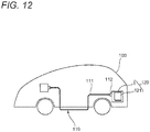
- FIG. 12 is a view showing a wire harness and an electric connection box according to an embodiment of the invention.
- an X-Y direction shown in FIG. 1 to FIG. 11 corresponds to a horizontal direction
- a Z direction corresponds to a vertical direction with a Z (+) direction as an upward direction.
- a wire harness 110 is installed in an automobile 100.
- the wire harness 110 includes a wiring portion 111 and an end portion 112.
- An electric connection box 120 is provided in the end portion 112 of the wire harness.
- the electric connection box 120 includes a housing 1 as shown in, for example, FIG. 1 and a plurality of electronic components 121 ( FIG. 12 ) that are housed in the housing 1.
- the electric connection box 120 according to the present embodiment is mounted at a position that is covered by water such as salt water and rain water that includes an impure part while the automobile 100 is traveling.
- the housing 1 includes a case 2, a cover 3, a packing 4, and four fastening members 5.
- the case 2 is a resin molded article that has a case body 6 and a flange portion 7, and is formed in a bottomed box shape in the present embodiment.
- the case body 6 has an opening 8 substantially square in a plan view, a hollow internal space 9 that communicates with the opening 8 and is located below the opening 8, four side walls 10 that form the opening 8 and the internal space 9, and a bottom wall (not shown) that is located on a lower portion of the internal space 9.
- the opening 8 is formed as an insertion port of the plurality of electronic components 121.
- the internal space 9 is formed into a space large enough to house the plurality of electronic components 121.
- Each of the side walls 10 has a wall shape that has a desired thickness.
- An opening edge portion 11 which has a substantially rectangular frame shape in a plan view is formed at upper ends of the side walls 10 and at a periphery of the opening 8. The opening edge portion 11 is formed flat.
- Fastening portions 13 are formed at four corners of the opening edge portion 11, respectively.
- Each of the fastening portions 13 includes an insert-molded nut (not shown).
- Each of the fastening portion 13 shown in FIG. 1 is a hole of the nut.
- the cover 3 has fastening portions 21 that are formed to penetrate the cover 3 at positions corresponding to the holes of the nuts.
- the fastening portions 13 of the case 2 are formed at positions each straddling a part of the flange portion 7.
- the flange portion 7 has a flange shape that surrounds an outer side of the opening edge portion 11.
- An upper surface of the flange portion 7 is formed flat. That is, the upper surface of the flange portion 7 and the opening edge portion 11 are formed on the same plane. In other words, the upper surface of the flange portion 7 and the opening edge portion 11 are formed in a shape having no step.
- the upper surface of the housing 1 that includes the upper surface of the flange portion 7, the opening edge portion 11 and the opening 8 constitute a first surface 12.
- the first surface 12 is formed into a flat surface around the opening 8 as described above.
- a packing groove 14 and a groove portion 15 are formed on the first surface 12.
- the packing groove 14 is formed as a portion for attaching the packing 4.
- the packing groove 14 is disposed at a position in a vicinity of the opening 8 and has a groove shape that surrounds the opening 8. "A position in a vicinity of the opening 8" is, for example, a position which is closer to the opening 8 than a center of the opening edge portion 11 between a radial inner end and a radial outer end of the opening edge portion 11.
- the packing groove 14 is formed in a portion where the packing 4 is kept in close contact with the case 2 and the cover 3 in a state where the packing 4 is compressed to have a substantially elliptical cross-sectional shape.
- the groove portion 15 is formed on a radially outer side of the packing groove 14 on the first surface 12 of the case 2.
- the groove portion 15 has a groove shape capable of storing water that includes, for example, salt.
- the groove portion 15 is formed on a radially outer side of the four fastening portions 13 and at a position in a vicinity of the fastening portions 13 in the example of FIG. 1 to FIG. 3 (the first example of the groove portion 15).
- a position in a vicinity of the fastening portions 13 is, for example, a position in the opening edge portion 11 where a shortest distance between the groove portion 15 and the fastening portions 13 is smaller than a shortest distance between the fastening portions 13 and the opening 8.
- the groove portion 15 has a recessed shape having a rectangular cross section, that has a groove side surface portion 15a substantially orthogonal to the first surface 12 and a bottom portion 15b substantially parallel to the first surface 12. Further, an opening width and a depth of the groove portion 15 are set to have dimensions necessary and sufficient for storing water that includes salt.
- the groove portion 15 is formed to have substantially the same cross-sectional size as the packing groove 14 is shown in FIG. 1 to FIG. 3 , the invention is not limited to this example, and the packing groove 14 and the groove portion 15 may have any groove shape.
- FIG. 4 and FIG. 5 show a second example of the groove portion 15.
- the groove portion 15 of the second example is formed at a radially inner side of the four fastening portions 13.
- FIG. 6 and FIG. 7 show a third example of the groove portion 15.
- Groove portions 15 of the third example are formed at positions at which adjacent fastening portions 13 are connected with each other, respectively.
- the groove portions 15 of the third example are formed such that the groove portions 15 extend straight to a vicinity of the fastening portions 13.
- the groove portions 15 are not formed in the vicinity of the fastening portions 13, there is no problem regarding infiltration of water since the water is difficult to pass through this portion due to the fastening by the fastening members 5.
- the groove portion 15 is formed to have substantially the same cross-sectional size as the packing groove 14 as in the example of FIG. 1 to FIG. 3 , the invention is not limited to this example.
- FIG. 8 shows a fourth example of the groove portion 15.
- the groove portion 15 of the fourth example is formed such that the bottom portion 15b (the bottom surface) is recessed in a V-shape.
- the recessed shape of the bottom surface of the groove portion 15 is not limited to the V-shape.
- FIG. 9 shows a fifth example of the groove portion 15.
- the groove portion 15 of the fifth example has a through hole 16 that communicates with an outside of the housing 1 in the bottom portion 15b.
- the through hole 16 is formed as a portion for draining water that includes, for example, salt.
- FIG. 10 shows a second example of the cover 3. In an example of FIG.
- FIG. 11 shows a sixth example of the groove portion 15.
- two groove portions 15 are formed to be a double in the radial direction.
- both of the groove portions 15 in the example of FIG. 1 to FIG. 3 and the groove portion 15 in the example of FIG. 6 and FIG. 7 are formed.
- the cover 3 is a resin molded article that has a cover body 17 and a collar portion 18 and is formed in a lid shape with a low ceiling in the present embodiment.
- the cover body 17 is formed as a portion that is located above the opening 8 of the case 2 when the cover 3 is attached to the case 2.
- the collar portion 18 is a plate-like portion that surrounds an edge portion of the cover body 17 and is formed as a portion that overlaps the opening edge portion 11 and the flange portion 7 of the case 2 when the cover 3 is attached to the case 2. That is, the collar portion 18 is formed as a portion which has a rectangular frame shape in a plan view. An upper surface and a lower surface of the collar portion 18 are formed flat. The lower surface of the collar portion 18 which is a flat surface constitutes a second surface 19.
- the second surface 19 is in surface contact with the first surface 12 of the case 2 when the cover 3 is attached to the case 2.
- the second surface 19 compresses the packing 4 that is housed in the packing groove 14 of the case 2, accordingly, the packing 4 is in close contact with the case 2 and the cover 3. Further, the second surface 19 covers the groove portion 15 of the case 2.
- the cover 3 of the second example has the protruding portion 20 that is formed on the second surface 19.
- the protruding portion 20 is formed as a portion which is inserted into the groove portion 15 of the first surface 12 in the case 2 with a gap therebetween.
- the protruding portion 20 is effective as a portion that complicates an infiltration path of water that includes, for example, salt and makes it difficult to reach the packing 4.
- the cover 3 is formed with four fastening portions 21.
- the fastening portions 21 of the cover 3 penetrate the collar portion 18.
- the fastening portions 21 of the cover 3 are formed in accordance with positions of the fastening portions 13 of the case 2.
- the fastening portions 21 and the fastening portions 13 are formed as portions to which the fastening members 5 are fastened.
- the packing 4 a rubber packing that is circular in a cross-sectional view and annular in a plan view is adopted.
- the packing 4 has a function as a sealing member for blocking water.
- the invention is not limited to the rubber packing, and a packing of other materials, for example liquid packing may be used. However, in a case of the liquid packing, since the cover cannot be detached upon maintenance and the like, the rubber packing is more effective than the liquid packing in terms of maintainability.
- the fastening members 5 are members for fastening and fixing the case 2 and the cover 3, and flange bolts 22 and nuts (not shown) or the like is adopted in the present embodiment.
- a method of assembling the housing 1 will be described with reference to FIG. 1 , FIG. 2 and FIG. 12 .
- the plurality of electronic components 121 are housed in the internal space 9 of the case body 6, and the packing 4 is attached to the packing groove 14 of the flange portion 7.
- the cover 3 is put on the case 2 and these are fastened by the fastening members 5
- the second surface 19 of the cover 3 is in surface contact with the first surface 12 of the case 2.
- the packing 4 is compressed and the packing 4 is in close contact with the case 2 and the cover 3 in a watertight manner.
- the end portion 112 of the wire harness 111 is pulled out of the housing 1.
- the assembly of the housing 1 is completed.
- this portion functions as a waterproof structure (an anticorrosion structure).
- the housing 1 is in a state where the first surface 12 of the case 2 and the second surface 19 of the cover 3 are in surface contact, a slight gap occurs due to some factor, and water that includes, for example, salt may infiltrate due to a capillary phenomenon and the like.
- the groove portion 15 is formed on the outer side of the packing groove 14, water can be stored in the groove portion 15 before reaching the packing 4, and as a result, crystallization of salt can occur in the groove portion 15 rather than in the packing 4. Therefore, deterioration of the packing 4 can be prevented, and a waterproof function (an anticorrosion function) can be maintained.
- the housing 1 since the groove portion 15 is formed on the outer side of the packing groove 14 and on the same plane as the packing groove 14, the housing 1 can be simplified and reduced in size. In addition, according to the housing 1, since a sufficient waterproof and anticorrosion function can be secured with only one packing 4, an increase in the number of components can be prevented, and assembly of the housing can be facilitated.
- the housing 1 is applied to the housing that configures an electrical connection box
- the invention may be applied to, for example, a housing for salt spray evaluation test, or a housing for an electronic component storage case.
- the structure of the present embodiment may be applied to a waterproof structure (an anticorrosion structure) of an electrical connection box that includes a frame and a lower cover that covers a lower opening of the frame.
- a waterproof structure an anticorrosion structure
- the same effect as described above can be obtained by forming a portion corresponding to the packing groove 14 and the groove portion 15 on a surface of the lower cover and forming a portion in surface contact with the surface on a frame side.
- the packing groove 14 and the groove portion 15 may be formed on the surface (the second surface) of the lower cover.
Landscapes
- Engineering & Computer Science (AREA)
- Microelectronics & Electronic Packaging (AREA)
- Mechanical Engineering (AREA)
- Architecture (AREA)
- Civil Engineering (AREA)
- Structural Engineering (AREA)
- Casings For Electric Apparatus (AREA)
- Connection Or Junction Boxes (AREA)
Claims (9)
- Gehäuse, das umfasst:einen Behälter (2), der eine erste Fläche (12) mit einer Öffnung (8) aufweist;eine Abdeckung (3), die die Öffnung (8) abdeckt und eine zweite Fläche (19) aufweist, die in Flächenkontakt mit der ersten Fläche (12) ist; sowieeine ringförmige Dichtung (4), die an einer Außenseite der Öffnung (8) angeordnet ist,wobei die erste Fläche (12) oder die zweite Fläche (19) eine Dichtungsnut (14), in der die Dichtung (4) angebracht ist, sowie einen Wassernut-Abschnitt (15) aufweist, der an einer Außenseite der Dichtungsnut (14) angeordnet und in der gleichen Ebene ausgebildet ist wie die Dichtungsnut (14).
- Gehäuse nach Anspruch 1, das des Weiteren umfasst:eine Vielzahl von Befestigungselementen (5), die das Gehäuse (2) und die Abdeckung (3) befestigen,wobei das Gehäuse (2) und die Abdeckung (3) jeweils eine Vielzahl von Befestigungsabschnitten (13) aufweisen, die an Positionen an einer Außenseite der Dichtung (4) sowie der Dichtungsnut (14) ausgebildet sind und an denen die Vielzahl von Befestigungselementen (5) jeweils befestigt sind, undder Wassernut-Abschnitt (15) an einer Position angeordnet ist, an der die Vielzahl von Befestigungsabschnitten (13) angebracht sind.
- Gehäuse nach Anspruch 1, das des Weiteren umfasst:eine Vielzahl von Befestigungselementen (5), die das Gehäuse (2) und die Abdeckung (3) befestigen,wobei das Gehäuse (2) und die Abdeckung (3) jeweils eine Vielzahl von Befestigungsabschnitten (13) aufweisen, die an Positionen an einer Außenseite der Dichtung (4) sowie der Dichtungsnut (14) ausgebildet sind und an denen die Vielzahl von Befestigungselementen (5) jeweils befestigt sind, undder Wassernut-Abschnitt (15) an einer Position an einer Innenseite der Vielzahl von Befestigungsabschnitten (13) angeordnet ist.
- Gehäuse nach Anspruch 1, das des Weiteren umfasst:eine Vielzahl von Befestigungselementen (5), die das Gehäuse (2) und die Abdeckung (3) befestigen,wobei das Gehäuse (2) und die Abdeckung (3) jeweils eine Vielzahl von Befestigungsabschnitten (13) aufweisen, die an Positionen an einer Außenseite der Dichtung (4) sowie der Dichtungsnut (14) ausgebildet sind und an denen die Vielzahl von Befestigungselementen (5) jeweils befestigt sind, undder Wassernut-Abschnitt (15) an einer Position an einer Außenseite und in der Nähe der Vielzahl von Befestigungsabschnitten (13) angeordnet ist.
- Gehäuse nach einem der Ansprüche 1 bis 4, wobei eine Bodenfläche (15b) des Wassernut-Abschnitts (15) eine vertiefte Querschnittsform hat.
- Gehäuse nach einem der Ansprüche 1 bis 4, wobei ein Bodenabschnitt (15b) des Wassernut-Abschnitts (15) ein Durchgangsloch (16) aufweist, das mit einer Außenseite des Gehäuses (1) in Verbindung steht.
- Gehäuse nach einem der Ansprüche 1 bis 4, wobei eine andere von der ersten Fläche (12) und der zweiten Fläche (19) einen vorstehenden Abschnitt (20) aufweist, der so ausgeführt ist, dass er in den Wassernut-Abschnitt (15) mit einem Zwischenraum dazwischen eingeführt wird.
- Elektrischer Anschlusskasten, der umfasst:ein Gehäuse (1) nach einem der Ansprüche 1 bis 7 sowieeine Vielzahl elektronischer Bauteile (121), die in dem Gehäuse (1) aufgenommen sind.
- Kabelbaum, der umfasst:einen Verdrahtungsabschnitt (111), der in einem Kraftfahrzeug (100) installiert ist; undeinen Endabschnitt (112), der den elektrischen Anschlusskasten (120) nach Anspruch 8 enthält.
Applications Claiming Priority (1)
| Application Number | Priority Date | Filing Date | Title |
|---|---|---|---|
| JP2018115727A JP7164330B2 (ja) | 2018-06-19 | 2018-06-19 | 筐体、電気接続箱、及びワイヤハーネス |
Publications (2)
| Publication Number | Publication Date |
|---|---|
| EP3584121A1 EP3584121A1 (de) | 2019-12-25 |
| EP3584121B1 true EP3584121B1 (de) | 2021-11-17 |
Family
ID=66951842
Family Applications (1)
| Application Number | Title | Priority Date | Filing Date |
|---|---|---|---|
| EP19180728.8A Active EP3584121B1 (de) | 2018-06-19 | 2019-06-18 | Gehäuse, elektrischer anschlusskasten und kabelbaum |
Country Status (4)
| Country | Link |
|---|---|
| US (1) | US11063413B2 (de) |
| EP (1) | EP3584121B1 (de) |
| JP (1) | JP7164330B2 (de) |
| CN (1) | CN110621132B (de) |
Families Citing this family (6)
| Publication number | Priority date | Publication date | Assignee | Title |
|---|---|---|---|---|
| TWM561976U (zh) * | 2017-12-08 | 2018-06-11 | 和碩聯合科技股份有限公司 | 機殼結構 |
| JP7131465B2 (ja) * | 2019-04-03 | 2022-09-06 | 株式会社デンソー | 車両制御装置 |
| US11591996B2 (en) * | 2020-01-17 | 2023-02-28 | Martin Koebler | Emergency start |
| JP2022013151A (ja) * | 2020-07-03 | 2022-01-18 | 住友電装株式会社 | 電気接続箱の筐体 |
| US11088517B1 (en) * | 2020-08-17 | 2021-08-10 | Abb Schweiz Ag | Closure plates for electrical enclosures |
| DE112022005280T5 (de) | 2022-01-31 | 2024-11-14 | Fanuc Corporation | Dichtungsstruktur |
Family Cites Families (27)
| Publication number | Priority date | Publication date | Assignee | Title |
|---|---|---|---|---|
| US3974933A (en) * | 1975-11-14 | 1976-08-17 | General Signal Corporation | Explosion proof and watertight enclosure with inspectable means for verifying validity of reclosure |
| US5050764A (en) * | 1990-03-08 | 1991-09-24 | Pacesetter Infusion, Ltd. | Lateral compression sealing system and method of making seal |
| DE4325412A1 (de) * | 1993-07-29 | 1995-02-02 | Teves Gmbh Alfred | Elektrohydraulische Druckregelvorrichtung |
| DE9321190U1 (de) | 1993-09-13 | 1998-01-15 | Duerrwaechter E Dr Doduco | Bauteilesatz für ein Gehäuse aus Kunststoff zum Aufnehmen von elektrischen Bauelementen |
| JP2597037Y2 (ja) * | 1993-10-12 | 1999-06-28 | 住友電装株式会社 | 電気接続箱の嵌合構造 |
| JP3052843B2 (ja) * | 1996-07-03 | 2000-06-19 | 住友電装株式会社 | 電気接続箱 |
| JP3446483B2 (ja) * | 1996-07-03 | 2003-09-16 | 住友電装株式会社 | 電気接続箱 |
| DE19634673C2 (de) * | 1996-08-28 | 1998-08-27 | Stahl R Schaltgeraete Gmbh | Kunststoffgehäuse in der Zündschutzart "Druckfeste Kapselung" |
| JP2001326475A (ja) * | 2000-05-15 | 2001-11-22 | Nec Corp | 通信機器の防水構造 |
| JP4180248B2 (ja) | 2000-05-29 | 2008-11-12 | 矢崎総業株式会社 | 電気接続箱 |
| JP2002373512A (ja) | 2001-06-15 | 2002-12-26 | Yazaki Corp | 電子機器収容筐体 |
| JP2003101256A (ja) | 2001-09-21 | 2003-04-04 | Kyocera Corp | 屋外設置機器の防水構造 |
| JP4365338B2 (ja) * | 2005-03-17 | 2009-11-18 | トヨタ自動車株式会社 | 電子部品収容構造体 |
| TWI342180B (en) * | 2007-10-09 | 2011-05-11 | Asustek Comp Inc | Housing structure |
| JP4892527B2 (ja) | 2008-08-29 | 2012-03-07 | 日立オートモティブシステムズ株式会社 | 電子制御装置 |
| JP2011071362A (ja) | 2009-09-28 | 2011-04-07 | Kyocera Corp | 通信機器用の金属筺体 |
| JP2011239099A (ja) | 2010-05-07 | 2011-11-24 | Nec Casio Mobile Communications Ltd | 防水装置及び電子機器 |
| JP2013165560A (ja) * | 2012-02-10 | 2013-08-22 | Denso Corp | 電気接続箱 |
| US9917427B2 (en) | 2012-06-04 | 2018-03-13 | Seahorse Industries Ltd. | Underground utility box assembly |
| KR20140006392A (ko) * | 2012-07-05 | 2014-01-16 | 엘에스산전 주식회사 | 자동차용 전장부품 박스 |
| JP2014054034A (ja) | 2012-09-06 | 2014-03-20 | Auto Network Gijutsu Kenkyusho:Kk | 電気接続箱 |
| KR101469826B1 (ko) * | 2013-05-10 | 2014-12-05 | 현대오트론 주식회사 | 차량의 전자 제어 장치 |
| CN105101715B (zh) | 2014-04-25 | 2019-04-26 | 华为技术有限公司 | 防腐镁合金通讯设备及其制备方法 |
| CN204104255U (zh) | 2014-09-15 | 2015-01-14 | 浙江超威创元实业有限公司 | 电动车内pcb板保护结构 |
| CN204928549U (zh) | 2015-08-21 | 2015-12-30 | 东莞市讯源电子科技有限公司 | 一种具有防水功能的电源适配器 |
| JP6309497B2 (ja) | 2015-09-03 | 2018-04-11 | 矢崎総業株式会社 | 電気接続箱およびワイヤハーネス |
| CN108243588A (zh) | 2018-01-17 | 2018-07-03 | 山东超越数控电子股份有限公司 | 一种导电接触接缝处理结构 |
-
2018
- 2018-06-19 JP JP2018115727A patent/JP7164330B2/ja active Active
-
2019
- 2019-06-17 US US16/443,413 patent/US11063413B2/en not_active Expired - Fee Related
- 2019-06-18 EP EP19180728.8A patent/EP3584121B1/de active Active
- 2019-06-18 CN CN201910525085.8A patent/CN110621132B/zh active Active
Also Published As
| Publication number | Publication date |
|---|---|
| EP3584121A1 (de) | 2019-12-25 |
| JP7164330B2 (ja) | 2022-11-01 |
| CN110621132A (zh) | 2019-12-27 |
| CN110621132B (zh) | 2021-06-15 |
| JP2019220538A (ja) | 2019-12-26 |
| US20190386473A1 (en) | 2019-12-19 |
| US11063413B2 (en) | 2021-07-13 |
Similar Documents
| Publication | Publication Date | Title |
|---|---|---|
| EP3584121B1 (de) | Gehäuse, elektrischer anschlusskasten und kabelbaum | |
| US7762415B2 (en) | Waterproof box for a wiring harness connector | |
| US9431806B2 (en) | Waterproof box and electric junction box equipped with same | |
| JP4680231B2 (ja) | コネクタ | |
| US8420937B2 (en) | Enclosure of outdoor apparatus | |
| CN107210558B (zh) | 设备用连接器 | |
| US10992069B2 (en) | Terminal block | |
| US9374916B2 (en) | Electrical junction box | |
| JP5422306B2 (ja) | 車両用ルーフマウントアンテナ装置 | |
| JP2014082565A (ja) | 車両用アンテナカバー | |
| US9694763B2 (en) | Wire harness protector having grounding function | |
| US20140246217A1 (en) | Electrical junction box | |
| US11860295B2 (en) | Enclosure for electronics | |
| JP4966647B2 (ja) | 電気接続箱のシール構造 | |
| WO2016194588A1 (ja) | 電気接続箱及び電気接続箱の防水構造 | |
| JP5536170B2 (ja) | 防水ケース | |
| US11769993B2 (en) | Electrical junction box housing | |
| JP6668276B2 (ja) | 自動車用制御装置 | |
| US20190036267A1 (en) | Housing with Lid for Cable Lug | |
| TWI775407B (zh) | 室外設置型電子機器框體 | |
| JP2021044962A (ja) | 電気接続箱 | |
| JP5299219B2 (ja) | 電気接続箱 | |
| KR200428579Y1 (ko) | 와이어 하네스의 밀봉장치 | |
| JP2015146706A (ja) | カバー |
Legal Events
| Date | Code | Title | Description |
|---|---|---|---|
| PUAI | Public reference made under article 153(3) epc to a published international application that has entered the european phase |
Free format text: ORIGINAL CODE: 0009012 |
|
| STAA | Information on the status of an ep patent application or granted ep patent |
Free format text: STATUS: REQUEST FOR EXAMINATION WAS MADE |
|
| 17P | Request for examination filed |
Effective date: 20190618 |
|
| AK | Designated contracting states |
Kind code of ref document: A1 Designated state(s): AL AT BE BG CH CY CZ DE DK EE ES FI FR GB GR HR HU IE IS IT LI LT LU LV MC MK MT NL NO PL PT RO RS SE SI SK SM TR |
|
| AX | Request for extension of the european patent |
Extension state: BA ME |
|
| REG | Reference to a national code |
Ref country code: DE Ref legal event code: R079 Ref document number: 602019009300 Country of ref document: DE Free format text: PREVIOUS MAIN CLASS: B60R0016023000 Ipc: H01R0013520000 |
|
| RIC1 | Information provided on ipc code assigned before grant |
Ipc: H01R 13/52 20060101AFI20210720BHEP |
|
| GRAP | Despatch of communication of intention to grant a patent |
Free format text: ORIGINAL CODE: EPIDOSNIGR1 |
|
| STAA | Information on the status of an ep patent application or granted ep patent |
Free format text: STATUS: GRANT OF PATENT IS INTENDED |
|
| INTG | Intention to grant announced |
Effective date: 20210902 |
|
| GRAS | Grant fee paid |
Free format text: ORIGINAL CODE: EPIDOSNIGR3 |
|
| GRAA | (expected) grant |
Free format text: ORIGINAL CODE: 0009210 |
|
| STAA | Information on the status of an ep patent application or granted ep patent |
Free format text: STATUS: THE PATENT HAS BEEN GRANTED |
|
| AK | Designated contracting states |
Kind code of ref document: B1 Designated state(s): AL AT BE BG CH CY CZ DE DK EE ES FI FR GB GR HR HU IE IS IT LI LT LU LV MC MK MT NL NO PL PT RO RS SE SI SK SM TR |
|
| REG | Reference to a national code |
Ref country code: GB Ref legal event code: FG4D |
|
| REG | Reference to a national code |
Ref country code: IE Ref legal event code: FG4D |
|
| REG | Reference to a national code |
Ref country code: DE Ref legal event code: R096 Ref document number: 602019009300 Country of ref document: DE |
|
| REG | Reference to a national code |
Ref country code: AT Ref legal event code: REF Ref document number: 1448815 Country of ref document: AT Kind code of ref document: T Effective date: 20211215 |
|
| REG | Reference to a national code |
Ref country code: LT Ref legal event code: MG9D |
|
| REG | Reference to a national code |
Ref country code: NL Ref legal event code: MP Effective date: 20211117 |
|
| REG | Reference to a national code |
Ref country code: AT Ref legal event code: MK05 Ref document number: 1448815 Country of ref document: AT Kind code of ref document: T Effective date: 20211117 |
|
| PG25 | Lapsed in a contracting state [announced via postgrant information from national office to epo] |
Ref country code: RS Free format text: LAPSE BECAUSE OF FAILURE TO SUBMIT A TRANSLATION OF THE DESCRIPTION OR TO PAY THE FEE WITHIN THE PRESCRIBED TIME-LIMIT Effective date: 20211117 Ref country code: LT Free format text: LAPSE BECAUSE OF FAILURE TO SUBMIT A TRANSLATION OF THE DESCRIPTION OR TO PAY THE FEE WITHIN THE PRESCRIBED TIME-LIMIT Effective date: 20211117 Ref country code: FI Free format text: LAPSE BECAUSE OF FAILURE TO SUBMIT A TRANSLATION OF THE DESCRIPTION OR TO PAY THE FEE WITHIN THE PRESCRIBED TIME-LIMIT Effective date: 20211117 Ref country code: BG Free format text: LAPSE BECAUSE OF FAILURE TO SUBMIT A TRANSLATION OF THE DESCRIPTION OR TO PAY THE FEE WITHIN THE PRESCRIBED TIME-LIMIT Effective date: 20220217 Ref country code: AT Free format text: LAPSE BECAUSE OF FAILURE TO SUBMIT A TRANSLATION OF THE DESCRIPTION OR TO PAY THE FEE WITHIN THE PRESCRIBED TIME-LIMIT Effective date: 20211117 |
|
| PG25 | Lapsed in a contracting state [announced via postgrant information from national office to epo] |
Ref country code: IS Free format text: LAPSE BECAUSE OF FAILURE TO SUBMIT A TRANSLATION OF THE DESCRIPTION OR TO PAY THE FEE WITHIN THE PRESCRIBED TIME-LIMIT Effective date: 20220317 Ref country code: SE Free format text: LAPSE BECAUSE OF FAILURE TO SUBMIT A TRANSLATION OF THE DESCRIPTION OR TO PAY THE FEE WITHIN THE PRESCRIBED TIME-LIMIT Effective date: 20211117 Ref country code: PT Free format text: LAPSE BECAUSE OF FAILURE TO SUBMIT A TRANSLATION OF THE DESCRIPTION OR TO PAY THE FEE WITHIN THE PRESCRIBED TIME-LIMIT Effective date: 20220317 Ref country code: PL Free format text: LAPSE BECAUSE OF FAILURE TO SUBMIT A TRANSLATION OF THE DESCRIPTION OR TO PAY THE FEE WITHIN THE PRESCRIBED TIME-LIMIT Effective date: 20211117 Ref country code: NO Free format text: LAPSE BECAUSE OF FAILURE TO SUBMIT A TRANSLATION OF THE DESCRIPTION OR TO PAY THE FEE WITHIN THE PRESCRIBED TIME-LIMIT Effective date: 20220217 Ref country code: NL Free format text: LAPSE BECAUSE OF FAILURE TO SUBMIT A TRANSLATION OF THE DESCRIPTION OR TO PAY THE FEE WITHIN THE PRESCRIBED TIME-LIMIT Effective date: 20211117 Ref country code: LV Free format text: LAPSE BECAUSE OF FAILURE TO SUBMIT A TRANSLATION OF THE DESCRIPTION OR TO PAY THE FEE WITHIN THE PRESCRIBED TIME-LIMIT Effective date: 20211117 Ref country code: HR Free format text: LAPSE BECAUSE OF FAILURE TO SUBMIT A TRANSLATION OF THE DESCRIPTION OR TO PAY THE FEE WITHIN THE PRESCRIBED TIME-LIMIT Effective date: 20211117 Ref country code: GR Free format text: LAPSE BECAUSE OF FAILURE TO SUBMIT A TRANSLATION OF THE DESCRIPTION OR TO PAY THE FEE WITHIN THE PRESCRIBED TIME-LIMIT Effective date: 20220218 Ref country code: ES Free format text: LAPSE BECAUSE OF FAILURE TO SUBMIT A TRANSLATION OF THE DESCRIPTION OR TO PAY THE FEE WITHIN THE PRESCRIBED TIME-LIMIT Effective date: 20211117 |
|
| PG25 | Lapsed in a contracting state [announced via postgrant information from national office to epo] |
Ref country code: SM Free format text: LAPSE BECAUSE OF FAILURE TO SUBMIT A TRANSLATION OF THE DESCRIPTION OR TO PAY THE FEE WITHIN THE PRESCRIBED TIME-LIMIT Effective date: 20211117 Ref country code: SK Free format text: LAPSE BECAUSE OF FAILURE TO SUBMIT A TRANSLATION OF THE DESCRIPTION OR TO PAY THE FEE WITHIN THE PRESCRIBED TIME-LIMIT Effective date: 20211117 Ref country code: RO Free format text: LAPSE BECAUSE OF FAILURE TO SUBMIT A TRANSLATION OF THE DESCRIPTION OR TO PAY THE FEE WITHIN THE PRESCRIBED TIME-LIMIT Effective date: 20211117 Ref country code: EE Free format text: LAPSE BECAUSE OF FAILURE TO SUBMIT A TRANSLATION OF THE DESCRIPTION OR TO PAY THE FEE WITHIN THE PRESCRIBED TIME-LIMIT Effective date: 20211117 Ref country code: DK Free format text: LAPSE BECAUSE OF FAILURE TO SUBMIT A TRANSLATION OF THE DESCRIPTION OR TO PAY THE FEE WITHIN THE PRESCRIBED TIME-LIMIT Effective date: 20211117 Ref country code: CZ Free format text: LAPSE BECAUSE OF FAILURE TO SUBMIT A TRANSLATION OF THE DESCRIPTION OR TO PAY THE FEE WITHIN THE PRESCRIBED TIME-LIMIT Effective date: 20211117 |
|
| REG | Reference to a national code |
Ref country code: DE Ref legal event code: R097 Ref document number: 602019009300 Country of ref document: DE |
|
| PLBE | No opposition filed within time limit |
Free format text: ORIGINAL CODE: 0009261 |
|
| STAA | Information on the status of an ep patent application or granted ep patent |
Free format text: STATUS: NO OPPOSITION FILED WITHIN TIME LIMIT |
|
| 26N | No opposition filed |
Effective date: 20220818 |
|
| PG25 | Lapsed in a contracting state [announced via postgrant information from national office to epo] |
Ref country code: AL Free format text: LAPSE BECAUSE OF FAILURE TO SUBMIT A TRANSLATION OF THE DESCRIPTION OR TO PAY THE FEE WITHIN THE PRESCRIBED TIME-LIMIT Effective date: 20211117 |
|
| PG25 | Lapsed in a contracting state [announced via postgrant information from national office to epo] |
Ref country code: SI Free format text: LAPSE BECAUSE OF FAILURE TO SUBMIT A TRANSLATION OF THE DESCRIPTION OR TO PAY THE FEE WITHIN THE PRESCRIBED TIME-LIMIT Effective date: 20211117 |
|
| PG25 | Lapsed in a contracting state [announced via postgrant information from national office to epo] |
Ref country code: MC Free format text: LAPSE BECAUSE OF FAILURE TO SUBMIT A TRANSLATION OF THE DESCRIPTION OR TO PAY THE FEE WITHIN THE PRESCRIBED TIME-LIMIT Effective date: 20211117 |
|
| REG | Reference to a national code |
Ref country code: CH Ref legal event code: PL |
|
| REG | Reference to a national code |
Ref country code: BE Ref legal event code: MM Effective date: 20220630 |
|
| PG25 | Lapsed in a contracting state [announced via postgrant information from national office to epo] |
Ref country code: LU Free format text: LAPSE BECAUSE OF NON-PAYMENT OF DUE FEES Effective date: 20220618 Ref country code: IE Free format text: LAPSE BECAUSE OF NON-PAYMENT OF DUE FEES Effective date: 20220618 Ref country code: FR Free format text: LAPSE BECAUSE OF NON-PAYMENT OF DUE FEES Effective date: 20220630 Ref country code: CH Free format text: LAPSE BECAUSE OF NON-PAYMENT OF DUE FEES Effective date: 20220630 Ref country code: LI Free format text: LAPSE BECAUSE OF NON-PAYMENT OF DUE FEES Effective date: 20220630 |
|
| PG25 | Lapsed in a contracting state [announced via postgrant information from national office to epo] |
Ref country code: IT Free format text: LAPSE BECAUSE OF FAILURE TO SUBMIT A TRANSLATION OF THE DESCRIPTION OR TO PAY THE FEE WITHIN THE PRESCRIBED TIME-LIMIT Effective date: 20211117 Ref country code: BE Free format text: LAPSE BECAUSE OF NON-PAYMENT OF DUE FEES Effective date: 20220630 |
|
| GBPC | Gb: european patent ceased through non-payment of renewal fee |
Effective date: 20230618 |
|
| PG25 | Lapsed in a contracting state [announced via postgrant information from national office to epo] |
Ref country code: MK Free format text: LAPSE BECAUSE OF FAILURE TO SUBMIT A TRANSLATION OF THE DESCRIPTION OR TO PAY THE FEE WITHIN THE PRESCRIBED TIME-LIMIT Effective date: 20211117 Ref country code: CY Free format text: LAPSE BECAUSE OF FAILURE TO SUBMIT A TRANSLATION OF THE DESCRIPTION OR TO PAY THE FEE WITHIN THE PRESCRIBED TIME-LIMIT Effective date: 20211117 Ref country code: GB Free format text: LAPSE BECAUSE OF NON-PAYMENT OF DUE FEES Effective date: 20230618 |
|
| PG25 | Lapsed in a contracting state [announced via postgrant information from national office to epo] |
Ref country code: HU Free format text: LAPSE BECAUSE OF FAILURE TO SUBMIT A TRANSLATION OF THE DESCRIPTION OR TO PAY THE FEE WITHIN THE PRESCRIBED TIME-LIMIT; INVALID AB INITIO Effective date: 20190618 |
|
| PG25 | Lapsed in a contracting state [announced via postgrant information from national office to epo] |
Ref country code: TR Free format text: LAPSE BECAUSE OF FAILURE TO SUBMIT A TRANSLATION OF THE DESCRIPTION OR TO PAY THE FEE WITHIN THE PRESCRIBED TIME-LIMIT Effective date: 20211117 |
|
| PG25 | Lapsed in a contracting state [announced via postgrant information from national office to epo] |
Ref country code: MT Free format text: LAPSE BECAUSE OF FAILURE TO SUBMIT A TRANSLATION OF THE DESCRIPTION OR TO PAY THE FEE WITHIN THE PRESCRIBED TIME-LIMIT Effective date: 20211117 |
|
| PGFP | Annual fee paid to national office [announced via postgrant information from national office to epo] |
Ref country code: DE Payment date: 20250429 Year of fee payment: 7 |