EP3581815A1 - Bowdenzugaktuator - Google Patents
Bowdenzugaktuator Download PDFInfo
- Publication number
- EP3581815A1 EP3581815A1 EP18176977.9A EP18176977A EP3581815A1 EP 3581815 A1 EP3581815 A1 EP 3581815A1 EP 18176977 A EP18176977 A EP 18176977A EP 3581815 A1 EP3581815 A1 EP 3581815A1
- Authority
- EP
- European Patent Office
- Prior art keywords
- bowden cable
- lever
- actuator
- plunger
- guide
- Prior art date
- Legal status (The legal status is an assumption and is not a legal conclusion. Google has not performed a legal analysis and makes no representation as to the accuracy of the status listed.)
- Granted
Links
Images

Classifications
-
- F—MECHANICAL ENGINEERING; LIGHTING; HEATING; WEAPONS; BLASTING
- F16—ENGINEERING ELEMENTS AND UNITS; GENERAL MEASURES FOR PRODUCING AND MAINTAINING EFFECTIVE FUNCTIONING OF MACHINES OR INSTALLATIONS; THERMAL INSULATION IN GENERAL
- F16C—SHAFTS; FLEXIBLE SHAFTS; ELEMENTS OR CRANKSHAFT MECHANISMS; ROTARY BODIES OTHER THAN GEARING ELEMENTS; BEARINGS
- F16C1/00—Flexible shafts; Mechanical means for transmitting movement in a flexible sheathing
- F16C1/10—Means for transmitting linear movement in a flexible sheathing, e.g. "Bowden-mechanisms"
- F16C1/12—Arrangements for transmitting movement to or from the flexible member
- F16C1/16—Arrangements for transmitting movement to or from the flexible member in which the end-piece is guided rectilinearly
-
- F—MECHANICAL ENGINEERING; LIGHTING; HEATING; WEAPONS; BLASTING
- F16—ENGINEERING ELEMENTS AND UNITS; GENERAL MEASURES FOR PRODUCING AND MAINTAINING EFFECTIVE FUNCTIONING OF MACHINES OR INSTALLATIONS; THERMAL INSULATION IN GENERAL
- F16C—SHAFTS; FLEXIBLE SHAFTS; ELEMENTS OR CRANKSHAFT MECHANISMS; ROTARY BODIES OTHER THAN GEARING ELEMENTS; BEARINGS
- F16C1/00—Flexible shafts; Mechanical means for transmitting movement in a flexible sheathing
- F16C1/10—Means for transmitting linear movement in a flexible sheathing, e.g. "Bowden-mechanisms"
- F16C1/101—Intermediate connectors for joining portions of split flexible shafts and/or sheathings
-
- F—MECHANICAL ENGINEERING; LIGHTING; HEATING; WEAPONS; BLASTING
- F16—ENGINEERING ELEMENTS AND UNITS; GENERAL MEASURES FOR PRODUCING AND MAINTAINING EFFECTIVE FUNCTIONING OF MACHINES OR INSTALLATIONS; THERMAL INSULATION IN GENERAL
- F16C—SHAFTS; FLEXIBLE SHAFTS; ELEMENTS OR CRANKSHAFT MECHANISMS; ROTARY BODIES OTHER THAN GEARING ELEMENTS; BEARINGS
- F16C1/00—Flexible shafts; Mechanical means for transmitting movement in a flexible sheathing
- F16C1/10—Means for transmitting linear movement in a flexible sheathing, e.g. "Bowden-mechanisms"
- F16C1/102—Arrangements to mount end fittings of the sheathings to support walls or brackets
-
- F—MECHANICAL ENGINEERING; LIGHTING; HEATING; WEAPONS; BLASTING
- F16—ENGINEERING ELEMENTS AND UNITS; GENERAL MEASURES FOR PRODUCING AND MAINTAINING EFFECTIVE FUNCTIONING OF MACHINES OR INSTALLATIONS; THERMAL INSULATION IN GENERAL
- F16C—SHAFTS; FLEXIBLE SHAFTS; ELEMENTS OR CRANKSHAFT MECHANISMS; ROTARY BODIES OTHER THAN GEARING ELEMENTS; BEARINGS
- F16C1/00—Flexible shafts; Mechanical means for transmitting movement in a flexible sheathing
- F16C1/10—Means for transmitting linear movement in a flexible sheathing, e.g. "Bowden-mechanisms"
- F16C1/106—Plurality of transmitting means, e.g. two or more parallel "Bowden cables"
-
- F—MECHANICAL ENGINEERING; LIGHTING; HEATING; WEAPONS; BLASTING
- F16—ENGINEERING ELEMENTS AND UNITS; GENERAL MEASURES FOR PRODUCING AND MAINTAINING EFFECTIVE FUNCTIONING OF MACHINES OR INSTALLATIONS; THERMAL INSULATION IN GENERAL
- F16C—SHAFTS; FLEXIBLE SHAFTS; ELEMENTS OR CRANKSHAFT MECHANISMS; ROTARY BODIES OTHER THAN GEARING ELEMENTS; BEARINGS
- F16C2314/00—Personal or domestic articles, e.g. household appliances such as washing machines, dryers
Definitions
- the present invention relates to a Bowden cable actuator according to the preamble of claim 1, and a Bowden cable arrangement for actuating a drain valve according to claim 11, a drain valve arrangement according to claim 14 and a base cabinet according to claim 15.
- the operation of the drain valve by means of a Bowden cable is known from the prior art.
- the DE 20 2011 101 212 U1 such a Bowden cable.
- the pull rope of the Bowden cable after the DE 20 2011 101 212 U1 is operated by an operating lever which is pivoted.
- the swivel lever acts directly on the Bowden cable and moves the cable.
- Disadvantage of the DE 20 2011 101 212 U1 is the fact that a comparatively deep installation space is required. This can, for example, by Figure 3 be recognized well.
- the invention has for its object to provide a Bowden cable actuator which overcomes the disadvantages of the prior art.
- a Bowden cable actuator is to be specified which is more compact and in particular can be installed in a cabinet wall.
- a Bowden cable actuator for a Bowden cable with a dimensionally stable sheath and a traction cable mounted therein comprises a support element, a pivot lever which is pivotably mounted on the support element and which can be pivoted by a user, and a plunger mounted in a longitudinal guide on the support element with a connection point to which the pull cable of the Bowden cable is fastened and a link point to which the pivot lever is articulated.
- the ram can be moved in the longitudinal guide along a longitudinal direction.
- the ram is guided accordingly in the longitudinal guide.
- the swivel lever is connected via the articulation point of the plunger in such a way that the plunger can be moved in the longitudinal direction when the swivel lever is pivoted and thus moves the pull cable accordingly.
- the pivot axis about which the pivot lever can be pivoted is preferably oriented at right angles to the longitudinal direction. When viewed in the direction of the pivot axis, the pivot axis is preferably laterally offset from the longitudinal guide.
- the support element preferably has a receptacle for receiving the dimensionally stable sleeves.
- the plunger is preferably designed to be comparatively flat when viewed in the direction of the pivot axis. As a result, the compactness of the Bowden cable actuator can be increased further.
- the articulation point on the tappet is preferably a guide pin which engages in a guide track which can be pivoted with the pivoting lever. By pivoting the guideway, the plunger mounted in the longitudinal guide can be moved in the longitudinal direction.
- the guide pin is preferably at the end opposite the connection point at which the pull rope is attached.
- the guide track is preferably inclined at an angle to the longitudinal direction of the longitudinal guide, the guide track in a first and a second end position preferably being at an angle of 45 ° to the longitudinal guide, and the guide track being in the center between the two end positions is preferably at an angle of 90 ° to the longitudinal guide.
- the pivot angle of the pivot lever between the two end positions is preferably 90 °. Other angles are also conceivable.
- the longitudinal guide is preferably delimited by a rear wall, by side walls protruding from the rear wall, the plunger, in particular with regard to its extension transverse to the longitudinal direction, lying completely in the longitudinal guide and one of the side walls having a through opening for the passage of the traction cable.
- the longitudinal guide relative to the rear wall is preferably delimited by a closure plate.
- the closure plate preferably has a small thickness, so that the thickness of the Bowden cable actuator is not further increased by the closure plate.
- the thickness of the support element and the closure plate connected to it is preferably in the range from 10 millimeters to 25 millimeters from the rear to the exposed front surface of the closure plate.
- the longitudinal guide is followed by a cavity, the plunger protruding into the cavity with its articulation point and being connected there to the pivoting lever.
- the guideway of the pivot lever is preferably located in said cavity.
- the pivot lever is preferably arranged offset from the guideway and the plunger, in particular in such a way that an intermediate space is created between the guideway and the plunger for accommodating parts of a side wall of cabinet furniture.
- this means that the swivel lever is at a distance from the support element when viewed in the direction of the swivel axis.
- the Bowden cable actuator preferably has a swivel element which is connected in a rotationally fixed manner to the swivel lever and which is connected to the articulation point of the tappet.
- the Bowden cable actuator preferably also has a panel element which is arranged in the region of the pivoting lever, the pivoting element protruding with an axis section through an opening in the panel element.
- a Bowden cable arrangement for transmitting a movement of a first Bowden cable to a second Bowden cable is specified for the purpose of actuating a drain valve.
- the Bowden cable arrangement is based in particular on the task of creating a device which works well and reliably in various installation situations.
- the Bowden cable arrangement comprises a first Bowden cable, a second Bowden cable and a Bowden cable actuator, in particular a Bowden cable actuator as described above.
- the first Bowden cable can be actuated by the Bowden cable actuator.
- the second Bowden cable is connected to a drain valve and operates it accordingly.
- the Bowden cable arrangement has a transmission element with a pivotable transmission lever, which transmission lever is connected to the first Bowden cable with a first lever arm and is connected to the second Bowden cable with a second lever arm, the transmission lever pivoting through the first Bowden cable when the actuator is actuated and so the second Bowden cable is operated.
- the implementation of the movement from the first Bowden cable to the second Bowden cable via the transmission element has the advantage that the second Bowden cable can be arranged in relation to the drain valve at a determined point in the specific installation situation. That means that in the installation situation, only the first Bowden cable has to be adjusted or its length selected.
- the transmission element and the second Bowden cable from arrangement to arrangement are preferably essentially identical or identical, while the length of the first Bowden cable can vary from arrangement to arrangement.
- the Bowden cable arrangement comprises a third Bowden cable, the third Bowden cable being actuated by a further Bowden cable actuator, in particular by a further Bowden cable actuator as described above.
- the transmission lever further comprises a third lever arm which is connected to the third Bowden cable, the transmission lever being pivoted by the third Bowden cable when the further Bowden cable actuator is actuated, and the second Bowden cable is thus actuated.
- said drain valve can also be actuated.
- this is advantageous because an actuator can be arranged on both sides of the washstand.
- the transmission lever is preferably mounted on a base plate, which also has a number of receptacles corresponding to the number of Bowden cables for receiving the dimensionally stable sleeves.
- a drain valve arrangement comprises a Bowden cable arrangement as described above and a drain valve with a valve flap, the second Bowden cable acting on the valve flap.
- a base cabinet for a washstand comprises at least one side wall with a recess facing the interior of the base cabinet, in which the Bowden cable actuator is embedded, the pivoting lever being arranged on the outside of the base cabinet.
- the support element is advantageously completely in the said recess stored.
- the Bowden cable 2a comprises a dimensionally stable sheath 3 and a pull cable 4 stored therein.
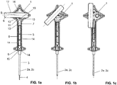
- the Bowden cable actuator 1 comprises a support element 5, one on the support element 5 pivotably mounted pivot lever 6, which can be pivoted by a user, and a plunger 8 mounted in a longitudinal guide 7 on the support element 5 with a connection point 9 to which the pull cable 4 of the Bowden cable 2a is fastened.
- the plunger 8 further comprises a pivot point 10 at which the pivot lever 6 is articulated such that an actuating movement of the pivot lever 6 can be transmitted to the plunger 8.
- the pivot lever 6 is connected via the articulation point 10 of the plunger 8 in such a way that the plunger 8 can be moved in the longitudinal direction L when the pivot lever 6 is pivoted and thus moves the traction cable 4 accordingly.
- the pivot axis S is at right angles to the longitudinal direction L.
- the swivel axis S is perpendicular to the surface of the blade.
- the pivot axis S is laterally offset from the longitudinal guide 7, as seen in the direction of the pivot axis S.
- the articulation point 10 on the plunger 8 is a guide pin 11, which is arranged here at the upper end of the plunger 8.
- the guide pin 11 protrudes into a guide track 12 which can be pivoted with the pivot lever 6, the pusher 8 mounted in the longitudinal guide 7 being movable in the longitudinal direction L by the pivoting of the guide track 12.
- the pivoting of the guideway 12 is also in the Figures 1a to 1c shown. During the pivoting, there is a relative movement between the guideway 12 and the guide pin 11, as a result of which the plunger 8 is raised.
- the guideway 12 is oriented at an angle to the longitudinal direction L of the longitudinal guide 7.
- the guide track 12 is at an angle of 45 degrees to the longitudinal guide 7.
- the guide track 12 is at an angle of 90 degrees to the longitudinal guide 7.
- the middle position is in the Figure 1b shown.
- the pulling rope 4 is oriented in the support element 5 essentially parallel to the longitudinal direction L and opens out of the longitudinal guide 7 via a through opening 15.
- the longitudinal guide 7 is delimited by a rear wall 13, with side walls 14 protruding from the rear wall 13, which laterally limit the longitudinal guide 7. This creates a cavity which provides the longitudinal guide 7.
- the plunger 8 is arranged lying completely in the guideway 12 with respect to its extent transverse to the longitudinal direction L.
- the side walls 14 have said passage opening 15 for the passage of the pull rope 4 in the lower region.
- the plunger 8 has a length in the longitudinal direction L, which allows good guidance inside the longitudinal guide 7.
- the longitudinal guide 7 is delimited by a closing plate 36.
- the closure plate 36 can preferably be connected to the support element 5.
- the longitudinal guide 7 is followed by a cavity 16 on the upper side.
- the plunger 8 projects with its articulation point 10 into the cavity 16 and is there connected to the pivot lever 6.
- the guideway 12 of the pivot lever 6 is preferably in the said cavity.
- the guideway 12 is part of a swivel element 19.
- the swivel element 19 lies in the said cavity 16 and can be swiveled there.
- the pivot element 19 is rotatably connected to the pivot lever 6.
- the swivel element 19 has an axis section 21 which projects through an opening 37 in the closure plate 36. At the end which protrudes beyond the closure plate 36, the pivot lever 6 is corresponding attached.
- the Bowden cable actuator 1 has a panel element 20 which is arranged in the region of the pivot lever.
- the swivel element 19 is also passed with the axle section 21 through an opening 22 in the panel element 20.
- the panel element 20 essentially serves to achieve a corresponding veneering of a groove towards the outside when the Bowden cable actuator 1 is installed in a piece of furniture.
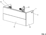
- FIG. 3 an installation situation of the Bowden cable actuator 1 is shown schematically.
- the Bowden cable actuator 1 is arranged here on a base cabinet 18 of a washstand.
- the Bowden cable actuator 1 is arranged in the side wall 32 of the base cabinet 18.
- the pivot lever 6 is arranged such that it is accessible from the outside. The pivot lever 6 can then be pivoted to the fixed side wall 32 accordingly.
- the Bowden cable acts on a drain valve 23.
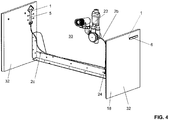
- the Bowden cable actuator lies in a recess 34 which faces the interior 33 of the base cabinet 18.
- the recess 34 extends into the side wall 32 so that the Bowden cable actuator 1 is accommodated therein.
- the axis element 21 of the pivot element 19 then penetrates the side wall 32 to the outside, where the pivot lever 6 is then articulated accordingly.
- the panel element 20 is located behind the pivot lever 6.
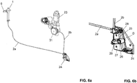
- the Bowden cable 2a is guided to the drain valve 23 via a transmission element 24.
- a valve flap 31 of the drain valve 23 is actuated accordingly via the pull rope.
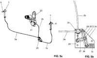
- the Figures 5a and 5b show a possible Bowden cable arrangement for transmitting a movement of a first Bowden cable 2a to a second Bowden cable 2b or for transmitting the movement of a third Bowden cable 2c to the second Bowden cable 2b.
- the first Bowden cable 2a and the third Bowden cable 2c are each operated with a Bowden cable actuator 1. As a result, the pull rope is moved accordingly.
- About one Transmission element 24 transmits the movement from the first Bowden cable 2a or from the third Bowden cable 2c to the second Bowden cable 2b.
- the transmission element 24 has a transmission lever 25 with three lever arms 26, 27, 28. The lever arms are each at right angles to one another and are mounted on a base plate 29 at a pivot point D.
- the transmission lever 25 When the first Bowden cable 2a is pulled, the transmission lever 25 is pivoted accordingly and also pulls the second Bowden cable 2b. Likewise, the transmission lever 25 is then pushed back again. The actuation of the third Bowden cable 2c then functions in a similar manner. Here, the transmission lever 25 is also pivoted, which leads to an actuation of the Bowden cable 2b.
- the base plate In addition to the mounting of the transmission lever 25, the base plate also has a number of receptacles 30 corresponding to the number of Bowden cables 2a to 2c for receiving the dimensionally stable sleeves 3.
- the design of the transmission element 24 is particularly advantageous because the second Bowden cable 2b, which is connected to the drain valve 23, can always have the same length. That is, drain valve 23, second Bowden cable 2b and transmission element 24 can be provided as a unit. In order to adapt to different sizes of base cabinets 18, only the length of the first or third Bowden cable 2a or 2c needs to be set.
Landscapes
- Engineering & Computer Science (AREA)
- General Engineering & Computer Science (AREA)
- Health & Medical Sciences (AREA)
- Oral & Maxillofacial Surgery (AREA)
- Mechanical Engineering (AREA)
- Mechanically-Actuated Valves (AREA)
Abstract
Description
- Die vorliegende Erfindung betrifft einen Bowdenzugaktuator nach dem Oberbegriff von Anspruch 1, sowie eine Bowdenzuganordnung zur Betätigung eines Abflussventils nach Anspruch 11, eine Abflussventilanordnung nach Anspruch 14 und einen Unterschrank nach Anspruch 15.
- Aus dem Stand der Technik ist die Betätigung von Abflussventil durch einen Bowdenzug bekannt. Beispielsweise offenbart die
DE 20 2011 101 212 U1 einen derartigen Bowdenzug. Das Zugseil des Bowdenzugs nach derDE 20 2011 101 212 U1 wird durch einen Betätigungshebel betätigt, welcher verschwenkt wird. Der Schwenkhebel wirkt dabei direkt auf den Bowdenzug ein und bewegt so das Zugseil. Nachteilig an derDE 20 2011 101 212 U1 ist die Tatsache, dass ein vergleichsweise tiefer Einbauraum benötigt wird. Dies kann beispielsweise von derFigur 3 gut erkannt werden. - Ausgehend von diesem Stand der Technik liegt der Erfindung eine Aufgabe zugrunde, einen Bowdenzugaktuator anzugeben, welcher die Nachteile des Standes der Technik überwindet. Insbesondere soll ein Bowdenzugaktuator angegeben werden, welcher kompakter ausgebildet ist und insbesondere in eine Schrankwand einbaubar ist.
- Diese Aufgabe löst der Bowdenzugaktuator nach dem Oberbegriff von Anspruch 1. Demgemäss umfasst ein Bowdenzugaktuator für einen Bowdenzug mit einer formstabilen Hülle und einem darin gelagerten Zugseil ein Supportelement, ein am Supportelement verschwenkbar gelagerten Schwenkhebel, der durch einen Benutzer verschwenkbar ist, und ein in einer Längsführung am Supportelement gelagerten Stössel mit einer Verbindungsstelle, an welcher das Zugseil des Bowdenzugs befestigt ist, und einer Anlenkstelle, an welcher der Schwenkhebel angelenkt ist. Der Stössel ist in der Längsführung entlang einer Längsrichtung bewegbar. Der Stössel wird dabei in der Längsführung entsprechend geführt. Der Schwenkhebel steht über die Anlenkstelle des Stössels derart in Verbindung, dass der Stössel bei einer Verschwenkung des Schwenkhebels in Längsrichtung bewegbar ist und so das Zugseil entsprechend bewegt.
- Durch die Umsetzung der Schwenkbewegung in eine Längsbewegung des Stössels der sodann die Bewegung auf das Zugseil überträgt ergeht der Vorteil, dass die Gesamtstruktur des Bowdenzugaktuators kompakter ausgebildet werden kann.
- Vorzugsweise ist die Schwenkachse, um welche der Schwenkhebel verschwenkbar ist, rechtwinklig zur Längsrichtung orientiert. Vorzugsweise ist die Schwenkachse in Richtung der Schwenkachse gesehen seitlich versetzt zur Längsführung angeordnet.
- Vorzugsweise weist das Supportelement eine Aufnahme für die Aufnahme der formstabilen Hüllen auf.
- Vorzugsweise ist der Stössel in Richtung der Schwenkachse gesehen vergleichsweise flach ausgebildet. Hierdurch kann die Kompaktheit des Bowdenzugaktuators weiter erhöht werden.
- Vorzugsweise ist die Anlenkstelle am Stössel ein Führungszapfen, welcher in eine mit dem Schwenkhebel verschwenkbare Führungsbahn eingreift. Durch die Verschwenkung der Führungsbahn ist der in der Längsführung gelagerte Stössel in Längsrichtung bewegbar.
- Der Führungszapfen liegt vorzugsweise am Ende gegenüber der Verbindungsstelle, an welcher das Zugseil befestigt ist.
- Vorzugsweise ist die Führungsbahn winklig geneigt zur Längsrichtung der Längsführung, wobei die Führungsbahn in einer ersten und einer zweiten Endstellung vorzugsweise in einem Winkel von 45° zur Längsführung steht, und wobei die Führungsbahn mittig zwischen den beiden Endstellungen vorzugsweise in einem Winkel von 90° zur Längsführung steht.
- Der Verschwenkwinkel des Schwenkhebels zwischen den beiden Endlagen ist vorzugsweise 90°. Andere Winkel sind auch denkbar.
- Vorzugsweise wird die Längsführung durch eine Rückwand, durch von der Rückwand wegstehende Seitenwände begrenzt, wobei der Stössel, insbesondere bezüglich seiner Ausdehnung quer zur Längsrichtung gesehen, vollständig in der Längsführung liegt und wobei eine der Seitenwände eine Durchführöffnung für die Durchführung des Zugseils aufweist.
- Vorzugsweise wird die Längsführung gegenüber der Rückwand durch eine Verschlussplatte begrenzt.
- Die Verschlussplatte weist vorzugsweise eine geringe Dicke auf, so dass die Dicke des Bowdenzugaktuator durch die Verschlussplatte nicht weiter erhöht wird.
- Vorzugsweise ist die Dicke des Supportelementes und der damit verbundenen Verschlussplatte von der Rückseite bis zur freiliegenden Frontfläche der Verschlussplatte im Bereich von 10 Millimetern bis 25 Millimetern.
- Vorzugsweise schliesst sich der Längsführung ein Hohlraum an, wobei der Stössel mit seiner Anlenkstelle in den Hohlraum einragt und dort mit dem Schwenkhebel in Verbindung steht.
- Vorzugsweise liegt die Führungsbahn des Schwenkhebels im besagten Hohlraum.
- Vorzugsweise ist der Schwenkhebel von der Führungsbahn und dem Stössel abgesetzt angeordnet, insbesondere derart, dass zwischen der Führungsbahn und dem Stössel ein Zwischenraum für die Aufnahme von Teilen einer Seitenwand eines Schrankmöbels geschaffen wird. Das heisst mit anderen Worten, dass der Schwenkhebel in Richtung der Schwenkachse gesehen mit einem Abstand zum Supportelement steht.
- Vorzugsweise weist der Bowdenzugaktuator ein mit dem Schwenkhebel drehfest in Verbindung stehendes Schwenkelement auf, welches mit der Anlenkstelle des Stössels in Verbindung steht.
- Vorzugsweise weist der Bowdenzugaktuator weiter ein Blendenelement auf, welches im Bereich des Schwenkhebels angeordnet ist, wobei das Schwenkelement mit einem Achsenabschnitt durch eine Öffnung im Blendenelement hindurch ragt.
- Weiter wird eine Bowdenzuganordnung zur Übertragung einer Bewegung eines ersten Bowdenzuges auf einen zweiten Bowdenzug angeben zwecks Betätigung eines Abflussventils angegeben. Der Bowdenzuganordnung liegt insbesondere die Aufgabe zugrunde, eine Einrichtung zu schaffen, welche in verschiedenen Einbausituationen gut und zuverlässig funktioniert. Die Bowdenzuganordnung umfasst einen ersten Bowdenzug, einen zweiten Bowdenzug und einen Bowdenzugaktuator, insbesondere einen Bowdenzugaktuator nach obiger Beschreibung. Der erste Bowdenzug wird durch den Bowdenzugaktuator betätigbar. Der zweite Bowdenzug steht mit einem Abflussventil in Verbindung und betätigt dieses entsprechend. Weiter weist die Bowdenzuganordnung ein Übertragungselement mit einem verschwenkbaren Übertragungshebel auf, welcher Übertragungshebel mit einem ersten Hebelarm mit dem ersten Bowdenzug in Verbindung steht und mit einem zweiten Hebelarm mit dem zweiten Bowdenzug in Verbindung steht, wobei der Übertragungshebel bei Betätigung des Aktuators durch den ersten Bowdenzug verschwenkt wird und so der zweiten Bowdenzug betätigt wird.
- Die Umsetzung der Bewegung vom ersten Bowdenzug zum zweiten Bowdenzug über das Übertragungselement hat den Vorteil, dass der zweite Bowdenzug in Relation zum Abflussventil an einer determinierten Stelle in der konkreten Einbausituation angeordnet werden kann. Das heiss, es ist in der Einbausituation lediglich der erste Bowdenzug anzupassen bzw. dessen Länge zu wählen. Für den Einbau der Bowdenzuganordnung in einem Unterschrank eines Waschtisches heisst dies, dass der zweite Bowdenzug und das Übertragungselement immer an der gleichen Stelle im Unterschrank anzuordnen sind, während die Länge des ersten Bowdenzugs auf die Grösse, insbesondere die Breite des Unterschranks angepasst werden kann.
- In allgemeinen Worten ausgedrückt, ist bei einer Serie von Bowdenzuganordnungen das Übertragungselement und der zweite Bowdenzug von Anordnung zur Anordnung vorzugsweise im Wesentlichen identisch oder gleich ausgebildet, während die Länge des ersten Bowdenzuges von Anordnung zu Anordnung unterschiedlich sein kann.
- In einer Weiterbildung umfasst die Bowdenzuganordnung einen dritten Bowdenzug, wobei der dritte Bowdenzug durch einen weiteren Bowdenzugaktuator, insbesondere durch einen weiteren Bowdenzugaktuator nach obiger Beschreibung, betätigt wird. Der Übertragungshebel umfasst weiter einen dritten Hebelarm, welcher mit dem dritten Bowdenzug in Verbindung steht, wobei der Übertragungshebel bei Betätigung des weiteren Bowdenzugaktuator durch den dritten Bowdenzug verschwenkt wird und so der zweite Bowdenzug betätigt wird.
- Durch die Anordnung des dritten Bowdenzugaktuators kann das besagte Abflussventil ebenfalls betätigt werden. Im Zusammenhang mit der Anordnung an einem Waschtisch bzw. einem Unterschrank eines Waschtisches ist dies vorteilhaft, weil so beidseitig zum Waschtisch ein Aktuator angeordnet werden kann.
- Vorzugsweise ist der Übertragungshebel auf einer Grundplatte gelagert, welche zudem eine der Anzahl der Bowdenzüge entsprechende Anzahl von Aufnahmen für die Aufnahme der formstabilen Hüllen aufweist.
- Eine Abflussventilanordnung umfasst eine Bowdenzuganordnung nach obiger Beschreibung und ein Abflussventil mit einer Ventilklappe, wobei der zweite Bowdenzug auf die Ventilklappe wirkt.
- Ein Unterschrank für einen Waschtisch umfasst mindestens eine Seitenwand mit einer zum Innenraum des Unterschrankes zugewandten Ausnehmung, in welcher der Bowdenzugaktuator eingelassen ist, wobei der Schwenkhebel aussenseitig zum Unterschrank angeordnet ist.
- Vorteilhafterweise ist das Supportelement vollständig in der besagten Ausnehmung gelagert.
- Weitere Ausführungsformen sind in den abhängigen Ansprüchen angegeben.
- Bevorzugte Ausführungsformen der Erfindung werden im Folgenden anhand der Zeichnungen beschrieben, die lediglich zur Erläuterung dienen und nicht einschränkend auszulegen sind. In den Zeichnungen zeigen:
- Fig. 1a-1c
- Frontansichten einer Ausführungsform des erfindungsgemässen Bowdenzugaktuators;
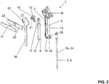
- Fig. 2
- eine Explosionsansicht des Bowdenzugaktuators nach
Figur 1 ; - Fig. 3
- eine perspektivische Ansicht eines Unterschrankes mit dem Bowdenzugaktuator nach
Figur 1 ; - Fig. 4
- eine weitere perspektivische Ansicht eines Unterschrankes mit dem Bowdenzugaktuator nach
Figur 1 ; - Fig. 5a/5b
- eine erste Konfiguration einer Bowdenzuganordnung mit einem Abflussventil;
- Fig. 6a/6b
- eine zweite Konfiguration einer Bowdenzuganordnung mit einem Abflussventil; und
- Fig. 7a/7b
- eine dritte Konfiguration einer Bowdenzuganordnung mit einem Abflussventil.
- In den
Figuren 1a bis 1c wird ein erfindungsgemässer Bowdenzugaktuator 1 für einen Bowdenzug 2a gezeigt. - Der Bowdenzug 2a umfasst eine formstabile Hülle 3 und ein darin gelagertes Zugseil 4.
- Der Bowdenzugaktuator 1 umfasst ein Supportelement 5, ein am Supportelement 5 verschwenkbar gelagerten Schwenkhebel 6, der durch einen Benutzer verschwenkbar ist, und ein in einer Längsführung 7 am Supportelement 5 gelagerten Stössel 8 mit einer Verbindungsstelle 9, an welcher das Zugseil 4 des Bowdenzugs 2a befestigt ist.
- Weiter umfasst der Stössel 8 eine Anlenkstelle 10, an welcher der Schwenkhebel 6 angelenkt ist, derart dass eine Betätigungsbewegung des Schwenkhebels 6 auf den Stössel 8 übertragbar ist. Der Schwenkhebel 6 steht über die Anlenkstelle 10 des Stössels 8 derart in Verbindung, dass der Stössel 8 bei einer Verschwenkung des Schwenkhebels 6 in Längsrichtung L bewegbar ist und so das Zugseil 4 entsprechend bewegt.
- In der
Figur 1a ist der Schwenkhebel 6 in einer ersten Endlage. In derFigur 1b ist der Schwenkhebel 6 um 45 Grad bezüglich der Ausgangslage derFigur 1a verschwenkt. Hierbei wurde der Stössel 8 in der Längsführung 7 in Längsrichtung L nach oben bewegt. Gleichzeitig wurde das Zugseil 4 entsprechend nach oben gezogen. In derFigur 1c wird eine zweite Endlage gezeigt. Hier steht der Schwenkhebel in einem Winkel von 90 Grad bezüglich der ersten Endlage und der Stössel 8 liegt an seiner oberen Position. Bei der Verschwenkung wurde das Zugseil 4 entsprechend gezogen. - Die Schwenkachse S, um welche der Schwenkhebel 6 verschwenkbar ist, steht rechtwinklig zur Längsrichtung L. In den gezeigten
Figuren 1a bis 1c verläuft die Schwenkachse S rechtwinklig zur Blattoberfläche. Die Schwenkachse S ist in Richtung der Schwenkachse S gesehen seitlich versetzt zur Längsführung 7 angeordnet. - Die Anlenkstelle 10 am Stössel 8 ist ein Führungszapfen 11, welcher hier am oberen Ende des Stössels 8 angeordnet ist. Der Führungszapfen 11 ragt in eine mit dem Schwenkhebel 6 verschwenkbare Führungsbahn 12 ein, wobei durch die Verschwenkung der Führungsbahn 12 der in der Längsführung 7 gelagerte Stössel 8 in Längsrichtung L bewegbar ist. Die Verschwenkung der Führungsbahn 12 wird ebenfalls in den
Figuren 1a bis 1c gezeigt. Während der Verschwenkung kommt es zu einer Relativbewegung zwischen Führungsbahn 12 und Führungszapfen 11, wodurch der Stössel 8 angehoben wird. - Die Führungsbahn 12 ist in der gezeigten Ausführungsform winklig geneigt zur Längsrichtung L der Längsführung 7 orientiert. In der ersten Endlage und auch in der zweiten Endlage, welche in den
Figuren 1a bzw.Figur 1c gezeigt wird, steht die Führungsbahn 12 in einem Winkel von 45 Grad zur Längsführung 7. In der Stellung mittig zwischen den beiden Endstellungen steht die Führungsbahn 12 in einem Winkel von 90 Grad zur Längsführung 7. Die Mittelstellung wird in derFigur 1b dargestellt. - Das Zugseil 4 ist im Supportelement 5 im Wesentlichen parallel zur Längsrichtung L orientiert und mündet über eine Durchführöffnung 15 aus der Längsführung 7. Im Bereich der Durchführöffnung 15 ist zugleich eine Aufnahme 35 für die Lagerung der formstabilen Hülle 3 vorgesehen.
- In der
Figur 2 wird eine perspektivische Explosionsdarstellung des Bowdenzugaktuators 1 gezeigt. Die Längsführung 7 wird in der gezeigten Ausführungsform durch eine Rückwand 13 begrenzt, wobei von der Rückwand 13 wegstehende Seitenwände 14 abstehen, welche die Längsführung 7 seitlich begrenzen. Hierdurch wird ein Hohlraum geschaffen, welcher die Längsführung 7 bereitstellt. Der Stössel 8 ist bezüglich seiner Ausdehnung quer zur Längsrichtung L gesehen vollständig in der Führungsbahn 12 liegend angeordnet. Die Seitenwände 14 weisen im unteren Bereich die besagte Durchführöffnung 15 für die Durchführung des Zugseiles 4 auf. Der Stössel 8 weist eine Länge in Längsrichtung L auf, welche eine gute Führung im Inneren der Längsführung 7 erlaubt. - Gegenüber der Rückwand 13 ist die Längsführung 7 durch eine Verschlussplatte 36 begrenzt. Die Verschlussplatte 36 lässt sich vorzugsweise mit dem Supportelement 5 verbinden.
- Der Längsführung 7 schliesst sich oberseitig ein Hohlraum 16 an. Der Stössel 8 ragt mit seiner Anlenkstelle 10 in den Hohlraum 16 ein und steht dort mit dem Schwenkhebel 6 in Verbindung. Die Führungsbahn 12 des Schwenkhebels 6 liegt dabei vorzugsweise im besagten Hohlraum. In der gezeigten Ausführungsform ist die Führungsbahn 12 Teil eines Schwenkelementes 19. Das Schwenkelement 19 liegt im besagten Hohlraum 16 und ist dort verschwenkbar. Das Schwenkelement 19 ist dabei drehfest mit dem Schwenkhebel 6 in Verbindung. Das Schwenkelement 19 weist einen Achsenabschnitt 21 auf, welches durch eine Öffnung 37 in der Verschlussplatte 36 hindurchragt. An dem Ende, welches über die Verschlussplatte 36 hervorsteht ist dabei der Schwenkhebel 6 entsprechend befestigt.
- Weiter weist der Bowdenzugaktuator 1 ein Blendenelement 20 auf, welches im Bereich des Schwenkhebels angeordnet ist. Dabei ist das Schwenkelement 19 ebenfalls mit dem Achsenabschnitt 21 durch eine Öffnung 22 im Blendenelement 20 hindurchgeführt. Das Blendenelement 20 dient im Wesentlich dazu beim Einbau des Bowdenzugaktuators 1 in ein Möbel eine entsprechende Verblendung einer Nut nach aussen hin zu erreichen.
- In der
Figur 3 wird schematisch eine Einbausituation des Bowdenzugaktuators 1 gezeigt. Der Bowdenzugaktuator 1 ist hier an einem Unterschrank 18 eines Waschtisches angeordnet. Im Konkreten ist der Bowdenzugaktuator 1 in der Seitenwand 32 des Unterschrankes 18 angeordnet. Dabei ist der Schwenkhebel 6 derart angeordnet, dass dieser von aussen her zugänglich ist. Der Schwenkhebel 6 kann dann zur feststehenden Seitenwand 32 entsprechend verschwenkt werden. Der Bowdenzug wirkt dabei auf ein Abflussventil 23. - In der
Figur 4 wird der Einbau des Bowdenzugaktuators noch weiter verdeutlicht. Der Bowdenzugaktuator liegt in einer Ausnehmung 34, welche dem Innenraum 33 des Unterschrankes 18 zugewandt ist. Die Ausnehmung 34 erstreckt sich dabei in die Seitenwand 32 hinein, sodass der Bowdenzugaktuator 1 darin Platz findet. Das Achsenelement 21 des Schwenkelementes 19 durchdringt dann die Seitenwand 32 nach aussen, wo dann der Schwenkhebel 6 entsprechend angelenkt ist. Hinter dem Schwenkhebel 6 befindet sich das Blendenelement 20. - Der Bowdenzug 2a wird in der gezeigten Ausführungsform über ein Übertragungselement 24 zum Abflussventil 23 geführt. Dabei wird über das Zugseil eine Ventilklappe 31 des Abflussventils 23 entsprechend betätigt.
- Die
Figuren 5a und 5b zeigen eine mögliche Bowdenzuganordnung zur Übertragung einer Bewegung eines ersten Bowdenzuges 2a auf einen zweiten Bowdenzug 2b bzw. zur Übertragung der Bewegung eines dritten Bowdenzugs 2c auf den zweiten Bowdenzug 2b. Der erste Bowdenzug 2a und der dritte Bowdenzug 2c werden mit jeweils einem Bowdenzugaktuator 1 betätigt. Hierdurch wird das Zugseil entsprechend bewegt. Über ein Übertragungselement 24 wird die Bewegung vom ersten Bowdenzug 2a bzw. vom dritten Bowdenzug 2c auf den zweiten Bowdenzug 2b übertragen. Das Übertragungselement 24 weist hierfür einen Übertragungshebel 25 mit drei Hebelarmen 26, 27, 28 auf. Die Hebelarme stehen jeweils rechtwinklig zueinander und sind an einem Drehpunkt D an einer Grundplatte 29 gelagert. Bei einem Zug vom ersten Bowdenzug 2a wird der Übertragungshebel 25 entsprechend verschwenkt und zieht dabei den zweiten Bowdenzug 2b ebenfalls. Gleichermassen wird der Übertragungshebel 25 dann auch wieder zurückgedrückt. In einer ähnlichen Art und Weise funktioniert dann die Betätigung des dritten Bowdenzugs 2c. Hierbei wird ebenfalls der Übertragungshebel 25 verschwenkt, was zu einer Betätigung des Bowdenzugs 2b führt. Nebst der Lagerung des Übertragungshebels 25 weist die Grundplatte weiterhin eine der Anzahl der Bowdenzüge 2a bis 2c entsprechende Anzahl von Aufnahmen 30 für die Aufnahme der formstabilen Hüllen 3 auf. - Die Ausbildung des Übertragungselementes 24 ist besonders vorteilhaft, weil der zweite Bowdenzug 2b, der mit dem Abflussventil 23 in Verbindung steht, immer die gleiche Länge aufweisen kann. Das heisst, Abflussventil 23, zweiter Bowdenzug 2b und Übertragungselement 24 können als Einheit bereitgestellt werden. Für die Anpassung auf verschiedene Grössen von Unterschränken 18 ist dann lediglich die Länge des ersten bzw. des dritten Bowdenzuges 2a bzw. 2c einzustellen.
- In den
Figuren 6a bis 7b werden weitere Bowdenzuganordnungen gezeigt. Hierbei handelt es sich aber jeweils um die Umsetzung von einem ersten Bowdenzug 2a auf den zweiten Bowdenzug 2b, wobei die Konfiguration "links" in denFiguren 6a, 6b und die Konfiguration "rechts" in denFiguren 7a, 7b gezeigt wird. Links und rechts heisst in diesem Zusammenhang die Anordnung des Bowdenzugaktuators 1 auf der einen bzw. der anderen Seite des Abflussventils 23.BEZUGSZEICHENLISTE 1 Bowdenzugaktuator 27 zweiter Hebelarm 2a, 2b, 2c Bowdenzug 28 erster Hebelarm 3 Hülle 29 Grundplatte 4 Zugseil 30 Aufnahme 5 Supportelement 31 Ventilklappe 6 Schwenkhebel 32 Seitenwand 7 Längsführung 33 Innenraum 8 Stössel 34 Ausnehmung 9 Verbindungsstelle 35 Aufnahme 10 Anlenkstelle 36 Verschlussplatte 11 Führungszapfen 37 Öffnung 12 Führungsbahn 13 Rückwand S Schwenkachse 14 Seitenwand D Drehpunkt 15 Durchführöffnung 16 Hohlraum 17 Zwischenraum 18 Schrankmöbel 19 Schwenkelement 20 Blendenelement 21 Achsenabschnitt 22 Öffnung 23 Abflussventil 24 Übertragungselement 25 Übertragungshebel 26 dritter Hebelarm
Claims (15)
- Bowdenzugaktuator (1) für einen Bowdenzug (2a, 2b, 2c) mit einer formstabilen Hülle (3) und einem darin gelagerten Zugseil (4) umfassend
ein Supportelement (5),
ein am Supportelement (5) verschwenkbar gelagerten Schwenkhebel (6), der durch einen Benutzer verschwenkbar ist, und
ein in einer Längsführung (7) am Supportelement (5) gelagerten Stössel (8) mit einer Verbindungsstelle (9), an welcher das Zugseil (4) des Bowdenzugs (2a, 2b, 2c) befestigt ist, und einer Anlenkstelle (10), an welcher der Schwenkhebel (6) angelenkt ist,
wobei der Stössel (8) in der Längsführung (7) entlang einer Längsrichtung (L) bewegbar ist, und
wobei der Schwenkhebel (6) über die Anlenkstelle (10) des Stössels (8) derart in Verbindung steht, dass der Stössel (8) bei einer Verschwenkung des Schwenkhebels (6) in Längsrichtung (L) bewegbar ist und so das Zugseil (4) entsprechend bewegt. - Bowdenzugaktuator (1) nach Anspruch 1, dadurch gekennzeichnet, dass die Schwenkachse (S), um welche der Schwenkhebel (6) verschwenkbar ist, rechtwinklig zur Längsrichtung (L) orientiert ist, und/oder dass die Schwenkachse (S) in Richtung der Schwenkachse (S) gesehen seitlich versetzt zur Längsführung (7) angeordnet ist.
- Bowdenzugaktuator (1) nach Anspruch 1 oder 2, dadurch gekennzeichnet, dass die Anlenkstelle (10) am Stössel (8) ein Führungszapfen (11) ist, welcher in eine mit dem Schwenkhebel (6) verschwenkbare Führungsbahn (12) eingreift, wobei durch die Verschwenkung der Führungsbahn (12) der in der Längsführung (7) gelagerte Stössel (8) in Längsrichtung (L) bewegbar ist.
- Bowdenzugaktuator (1) nach Anspruch 3, dadurch gekennzeichnet, dass die Führungsbahn (12) winklig geneigt zur Längsrichtung (L) der Längsführung (7) orientiert ist, wobei die Führungsbahn (12) in einer ersten und einer zweiten Endstellung vorzugsweise in einem Winkel von 45° zur Längsführung (7) steht, und wobei die Führungsbahn (12) mittig zwischen den beiden Endstellungen vorzugsweise in einem Winkel von 90° zur Längsführung (7) steht.
- Bowdenzugaktuator (1) nach einem der vorhergehenden Ansprüche, dadurch gekennzeichnet, dass die Längsführung (7) durch eine Rückwand (13), durch von der Rückwand (13) wegstehende Seitenwände (14) begrenzt wird, wobei der Stössel (8), insbesondere bezüglich seiner Ausdehnung quer zur Längsrichtung (L) gesehen, vollständig in der Längsführung (7) liegt und wobei eine der Seitenwände (14) eine Durchführöffnung (15) für die Durchführung des Zugseils (4) aufweist.
- Bowdenzugaktuator (1) nach Anspruch 5, dadurch gekennzeichnet, dass die Längsführung (7) gegenüber der Rückwand (13) durch eine Verschlussplatte (36) begrenzt ist.
- Bowdenzugaktuator (1) nach einem der vorhergehenden Ansprüche, dadurch gekennzeichnet, dass sich der Längsführung (7) ein Hohlraum (16) anschliesst, wobei der Stössel (8) mit seiner Anlenkstelle (10) in den Hohlraum (16) einragt und dort mit dem Schwenkhebel (6) in Verbindung steht, wobei die Führungsbahn (12) des Schwenkhebels (6) vorzugsweise im besagten Hohlraum (16) liegt.
- Bowdenzugaktuator (1) nach einem der vorhergehenden Ansprüche, dadurch gekennzeichnet, dass der Schwenkhebel (6) von der Führungsbahn (12) und dem Stössel (8) abgesetzt angeordnet ist, insbesondere derart, dass zwischen der Führungsbahn (12) und dem Stössel (8) ein Zwischenraum (17) für die Aufnahme von Teilen einer Seitenwand eines Schrankmöbels (18) geschaffen wird.
- Bowdenzugaktuator (1) nach einem der vorhergehenden Ansprüche, dadurch gekennzeichnet, dass der Bowdenzugaktuator (1) ein mit dem Schwenkhebel (6) drehfest in Verbindung stehendes Schwenkelement (19) aufweist, welches die Führungsbahn (12) aufweist und mit der Anlenkstelle (10) des Stössels (8) in Verbindung steht.
- Bowdenzugaktuator (1) nach Anspruch 9, dadurch gekennzeichnet, dass der Bowdenzugaktuator (1) weiter ein Blendenelement (20) aufweist, welches im Bereich des Schwenkhebels (6) angeordnet ist, wobei das Schwenkelement (19) mit einem Achsenabschnitt (21) durch eine Öffnung (22) im Blendenelement (20) hindurch ragt.
- Bowdenzuganordnung zur Übertragung einer Bewegung eines ersten Bowdenzuges (2a) auf einen zweiten Bowdenzug (2b), umfassend einen ersten Bowdenzug (2a), einen zweiten Bowdenzug (2b) und einen Bowdenzugaktuator (1), insbesondere einen Bowdenzugaktuator (1) nach einem der vorhergehenden Ansprüche,
wobei der erste Bowdenzug (2a) durch den Bowdenzugaktuator (1) betätigbar ist, wobei der zweite Bowdenzug (2b) mit einem Abflussventil (23) in Verbindung steht, und
wobei die Bowdenzuganordnung ein Übertragungselement (24) mit einem verschwenkbaren Übertragungshebel (25) aufweist, welcher Übertragungshebel (25) mit einem ersten Hebelarm (26) mit dem ersten Bowdenzug (2a) in Verbindung steht und mit einem zweiten Hebelarm (27) mit dem zweiten Bowdenzug (2b) in Verbindung steht, wobei der Übertragungshebel (25) bei Betätigung des Aktuators durch den ersten Bowdenzug (2a) verschwenkt wird und so der zweiten Bowdenzug (2b) betätigt wird. - Bowdenzuganordnung nach Anspruch 11, dadurch gekennzeichnet, dass die Bowdenzuganordnung einen dritten Bowdenzug (2c) umfasst, wobei der dritte Bowdenzug (2c) durch einen weiteren Bowdenzugaktuator (1), insbesondere durch einen weiteren Bowdenzugaktuator (1) nach einem der vorhergehenden Ansprüche 1 bis 10, betätigt wird,
wobei der Übertragungshebel (25) weiter einen dritten Hebelarm (28) umfasst, welcher mit dem dritten Bowdenzug (2c) in Verbindung steht,
wobei der Übertragungshebel (25) bei Betätigung des weiteren Bowdenzugaktuator (1) durch den dritten Bowdenzug (2c) verschwenkt wird und so der zweite Bowdenzug (2b) betätigt wird. - Bowdenzuganordnung nach Anspruch 11 oder 12, dadurch gekennzeichnet, dass der Übertragungshebel (25) auf einer Grundplatte (29) gelagert ist, welche zudem eine der Anzahl der Bowdenzüge (2a, 2b, 2c) entsprechende Anzahl von Aufnahmen (30) für die Aufnahme der formstabilen Hüllen (3) aufweist.
- Abflussventilanordnung umfassend eine Bowdenzuganordnung nach einem der Ansprüche 11 bis 13 und ein Abflussventil (23) mit einer Ventilklappe (31), wobei der zweite Bowdenzug (2b) auf die Ventilklappe (31) wirkt.
- Unterschrank (18) für einen Waschtisch umfassend mindestens eine Seitenwand (32) mit einer zum Innenraum (33) des Unterschrankes (18) zugewandten Ausnehmung (34), in welcher der Bowdenzugaktuator eingelassen ist, wobei der Schwenkhebel (6) aussenseitig angeordnet ist.
Priority Applications (3)
| Application Number | Priority Date | Filing Date | Title |
|---|---|---|---|
| PL18176977T PL3581815T3 (pl) | 2018-06-11 | 2018-06-11 | Układ cięgien Bowdena |
| DK18176977.9T DK3581815T3 (da) | 2018-06-11 | 2018-06-11 | Bowdenkabelaktuator |
| EP18176977.9A EP3581815B1 (de) | 2018-06-11 | 2018-06-11 | Bowdenzugaktuator |
Applications Claiming Priority (1)
| Application Number | Priority Date | Filing Date | Title |
|---|---|---|---|
| EP18176977.9A EP3581815B1 (de) | 2018-06-11 | 2018-06-11 | Bowdenzugaktuator |
Publications (2)
| Publication Number | Publication Date |
|---|---|
| EP3581815A1 true EP3581815A1 (de) | 2019-12-18 |
| EP3581815B1 EP3581815B1 (de) | 2021-08-04 |
Family
ID=62599474
Family Applications (1)
| Application Number | Title | Priority Date | Filing Date |
|---|---|---|---|
| EP18176977.9A Active EP3581815B1 (de) | 2018-06-11 | 2018-06-11 | Bowdenzugaktuator |
Country Status (3)
| Country | Link |
|---|---|
| EP (1) | EP3581815B1 (de) |
| DK (1) | DK3581815T3 (de) |
| PL (1) | PL3581815T3 (de) |
Citations (4)
| Publication number | Priority date | Publication date | Assignee | Title |
|---|---|---|---|---|
| FR32670E (fr) * | 1926-05-28 | 1928-02-15 | Dispositif de vidage de lavabo à tube flexible | |
| GB474566A (en) * | 1937-03-15 | 1937-11-03 | George Amos Service | Improvements in or relating to waste-fittings for baths, lavatory basins and sinks |
| DE102009012514A1 (de) * | 2009-03-10 | 2010-09-23 | Man Nutzfahrzeuge Ag | Vorrichtung zum Betätigen zweier Betätigungseinrichtungen, insbesondere Schließeinrichtungen |
| DE202011101212U1 (de) | 2011-05-20 | 2012-08-21 | Rehau Ag + Co | Vorrichtung zur Betätigung des Ablaufes einer Spüle |
-
2018
- 2018-06-11 DK DK18176977.9T patent/DK3581815T3/da active
- 2018-06-11 PL PL18176977T patent/PL3581815T3/pl unknown
- 2018-06-11 EP EP18176977.9A patent/EP3581815B1/de active Active
Patent Citations (4)
| Publication number | Priority date | Publication date | Assignee | Title |
|---|---|---|---|---|
| FR32670E (fr) * | 1926-05-28 | 1928-02-15 | Dispositif de vidage de lavabo à tube flexible | |
| GB474566A (en) * | 1937-03-15 | 1937-11-03 | George Amos Service | Improvements in or relating to waste-fittings for baths, lavatory basins and sinks |
| DE102009012514A1 (de) * | 2009-03-10 | 2010-09-23 | Man Nutzfahrzeuge Ag | Vorrichtung zum Betätigen zweier Betätigungseinrichtungen, insbesondere Schließeinrichtungen |
| DE202011101212U1 (de) | 2011-05-20 | 2012-08-21 | Rehau Ag + Co | Vorrichtung zur Betätigung des Ablaufes einer Spüle |
Also Published As
| Publication number | Publication date |
|---|---|
| EP3581815B1 (de) | 2021-08-04 |
| PL3581815T3 (pl) | 2021-12-13 |
| DK3581815T3 (da) | 2021-11-01 |
Similar Documents
| Publication | Publication Date | Title |
|---|---|---|
| EP3482024B1 (de) | Griffvorrichtung mit einem flächenbündigen griff | |
| EP2841667B1 (de) | Drehflügelantrieb | |
| DE102008010770B4 (de) | Befestigungsvorrichtung | |
| DE19626844C2 (de) | Vorrichtung zum Auslösen einer Gasfeder | |
| WO2020236098A1 (de) | Möbelbeschlag | |
| EP2143862A1 (de) | Parallelausstellfenster | |
| EP3918165A1 (de) | Klappenbeschlag für ein möbel | |
| DE102009022461B4 (de) | Betätigungsvorrichtung für eine Feststellbremse | |
| EP3098357B1 (de) | Betätigungsvorrichtung für ein ablaufventil eines spülkastens | |
| EP1669616B1 (de) | Betätigungszug | |
| DE2755787A1 (de) | Universaltuerschliesser | |
| DE19924028A1 (de) | Kraftfahrzeugtür | |
| EP3524765A1 (de) | Absenkbare einbruchsicherung | |
| EP3581815B1 (de) | Bowdenzugaktuator | |
| DE1932858A1 (de) | Ausstellschere fuer Fensterfluegel od.dgl.,insbesondere Oberlichter | |
| EP4077843B1 (de) | Führungsanordnung zur führung wenigstens eines bewegbaren möbelteils | |
| DE102012213786B3 (de) | Verlagerungsanordnung zur Verlagerung eines Flügels eines Fensters, einer Tür oder dergleichen relativ zu einer festen Einfassung | |
| DE102017105596A1 (de) | Antriebsvorrichtung für einen Flügel, insbesondere für einen Tür- oder Fensterflügel, und Rahmen mit einer solchen Antriebsvorrichtung | |
| DE4126115C1 (de) | ||
| DE4446904C1 (de) | Kraftfahrzeug-Türgriff | |
| CH450953A (de) | Raumabschlussorgan mit An- und Abdrückvorrichtung, insbesondere Kipp-Schwenkfenster oder -tür | |
| DE4412477B4 (de) | Bowdenzugvorrichtung mit einem Bowdenzug und einer Betätigungsvorrichtung | |
| DE1708204C3 (de) | Beschlag zur Lagerung und Führung eines Ausstellgestänges für die Flügel von Fenstern, Türen o.dgl. | |
| DE10303474A1 (de) | Offendachkonstruktion für ein Fahrzeug | |
| DE19834432A1 (de) | Vorrichtung zum wahlweisen Übertragen von Energie zwischen zwei Übertragungseinheiten |
Legal Events
| Date | Code | Title | Description |
|---|---|---|---|
| PUAI | Public reference made under article 153(3) epc to a published international application that has entered the european phase |
Free format text: ORIGINAL CODE: 0009012 |
|
| STAA | Information on the status of an ep patent application or granted ep patent |
Free format text: STATUS: THE APPLICATION HAS BEEN PUBLISHED |
|
| AK | Designated contracting states |
Kind code of ref document: A1 Designated state(s): AL AT BE BG CH CY CZ DE DK EE ES FI FR GB GR HR HU IE IS IT LI LT LU LV MC MK MT NL NO PL PT RO RS SE SI SK SM TR |
|
| AX | Request for extension of the european patent |
Extension state: BA ME |
|
| STAA | Information on the status of an ep patent application or granted ep patent |
Free format text: STATUS: REQUEST FOR EXAMINATION WAS MADE |
|
| 17P | Request for examination filed |
Effective date: 20200310 |
|
| RBV | Designated contracting states (corrected) |
Designated state(s): AL AT BE BG CH CY CZ DE DK EE ES FI FR GB GR HR HU IE IS IT LI LT LU LV MC MK MT NL NO PL PT RO RS SE SI SK SM TR |
|
| GRAP | Despatch of communication of intention to grant a patent |
Free format text: ORIGINAL CODE: EPIDOSNIGR1 |
|
| STAA | Information on the status of an ep patent application or granted ep patent |
Free format text: STATUS: GRANT OF PATENT IS INTENDED |
|
| INTG | Intention to grant announced |
Effective date: 20201019 |
|
| GRAJ | Information related to disapproval of communication of intention to grant by the applicant or resumption of examination proceedings by the epo deleted |
Free format text: ORIGINAL CODE: EPIDOSDIGR1 |
|
| STAA | Information on the status of an ep patent application or granted ep patent |
Free format text: STATUS: REQUEST FOR EXAMINATION WAS MADE |
|
| GRAP | Despatch of communication of intention to grant a patent |
Free format text: ORIGINAL CODE: EPIDOSNIGR1 |
|
| STAA | Information on the status of an ep patent application or granted ep patent |
Free format text: STATUS: GRANT OF PATENT IS INTENDED |
|
| INTC | Intention to grant announced (deleted) | ||
| INTG | Intention to grant announced |
Effective date: 20210315 |
|
| GRAS | Grant fee paid |
Free format text: ORIGINAL CODE: EPIDOSNIGR3 |
|
| GRAA | (expected) grant |
Free format text: ORIGINAL CODE: 0009210 |
|
| STAA | Information on the status of an ep patent application or granted ep patent |
Free format text: STATUS: THE PATENT HAS BEEN GRANTED |
|
| AK | Designated contracting states |
Kind code of ref document: B1 Designated state(s): AL AT BE BG CH CY CZ DE DK EE ES FI FR GB GR HR HU IE IS IT LI LT LU LV MC MK MT NL NO PL PT RO RS SE SI SK SM TR |
|
| REG | Reference to a national code |
Ref country code: GB Ref legal event code: FG4D Free format text: NOT ENGLISH |
|
| REG | Reference to a national code |
Ref country code: AT Ref legal event code: REF Ref document number: 1417262 Country of ref document: AT Kind code of ref document: T Effective date: 20210815 |
|
| REG | Reference to a national code |
Ref country code: CH Ref legal event code: EP |
|
| REG | Reference to a national code |
Ref country code: DE Ref legal event code: R096 Ref document number: 502018006396 Country of ref document: DE |
|
| REG | Reference to a national code |
Ref country code: IE Ref legal event code: FG4D Free format text: LANGUAGE OF EP DOCUMENT: GERMAN |
|
| REG | Reference to a national code |
Ref country code: NL Ref legal event code: FP |
|
| REG | Reference to a national code |
Ref country code: SE Ref legal event code: TRGR |
|
| REG | Reference to a national code |
Ref country code: DK Ref legal event code: T3 Effective date: 20211027 |
|
| REG | Reference to a national code |
Ref country code: LT Ref legal event code: MG9D |
|
| REG | Reference to a national code |
Ref country code: NO Ref legal event code: T2 Effective date: 20210804 |
|
| PG25 | Lapsed in a contracting state [announced via postgrant information from national office to epo] |
Ref country code: LT Free format text: LAPSE BECAUSE OF FAILURE TO SUBMIT A TRANSLATION OF THE DESCRIPTION OR TO PAY THE FEE WITHIN THE PRESCRIBED TIME-LIMIT Effective date: 20210804 Ref country code: BG Free format text: LAPSE BECAUSE OF FAILURE TO SUBMIT A TRANSLATION OF THE DESCRIPTION OR TO PAY THE FEE WITHIN THE PRESCRIBED TIME-LIMIT Effective date: 20211104 Ref country code: PT Free format text: LAPSE BECAUSE OF FAILURE TO SUBMIT A TRANSLATION OF THE DESCRIPTION OR TO PAY THE FEE WITHIN THE PRESCRIBED TIME-LIMIT Effective date: 20211206 Ref country code: HR Free format text: LAPSE BECAUSE OF FAILURE TO SUBMIT A TRANSLATION OF THE DESCRIPTION OR TO PAY THE FEE WITHIN THE PRESCRIBED TIME-LIMIT Effective date: 20210804 Ref country code: ES Free format text: LAPSE BECAUSE OF FAILURE TO SUBMIT A TRANSLATION OF THE DESCRIPTION OR TO PAY THE FEE WITHIN THE PRESCRIBED TIME-LIMIT Effective date: 20210804 Ref country code: FI Free format text: LAPSE BECAUSE OF FAILURE TO SUBMIT A TRANSLATION OF THE DESCRIPTION OR TO PAY THE FEE WITHIN THE PRESCRIBED TIME-LIMIT Effective date: 20210804 Ref country code: RS Free format text: LAPSE BECAUSE OF FAILURE TO SUBMIT A TRANSLATION OF THE DESCRIPTION OR TO PAY THE FEE WITHIN THE PRESCRIBED TIME-LIMIT Effective date: 20210804 |
|
| PG25 | Lapsed in a contracting state [announced via postgrant information from national office to epo] |
Ref country code: LV Free format text: LAPSE BECAUSE OF FAILURE TO SUBMIT A TRANSLATION OF THE DESCRIPTION OR TO PAY THE FEE WITHIN THE PRESCRIBED TIME-LIMIT Effective date: 20210804 Ref country code: GR Free format text: LAPSE BECAUSE OF FAILURE TO SUBMIT A TRANSLATION OF THE DESCRIPTION OR TO PAY THE FEE WITHIN THE PRESCRIBED TIME-LIMIT Effective date: 20211105 |
|
| REG | Reference to a national code |
Ref country code: DE Ref legal event code: R097 Ref document number: 502018006396 Country of ref document: DE |
|
| PG25 | Lapsed in a contracting state [announced via postgrant information from national office to epo] |
Ref country code: SM Free format text: LAPSE BECAUSE OF FAILURE TO SUBMIT A TRANSLATION OF THE DESCRIPTION OR TO PAY THE FEE WITHIN THE PRESCRIBED TIME-LIMIT Effective date: 20210804 Ref country code: SK Free format text: LAPSE BECAUSE OF FAILURE TO SUBMIT A TRANSLATION OF THE DESCRIPTION OR TO PAY THE FEE WITHIN THE PRESCRIBED TIME-LIMIT Effective date: 20210804 Ref country code: RO Free format text: LAPSE BECAUSE OF FAILURE TO SUBMIT A TRANSLATION OF THE DESCRIPTION OR TO PAY THE FEE WITHIN THE PRESCRIBED TIME-LIMIT Effective date: 20210804 Ref country code: EE Free format text: LAPSE BECAUSE OF FAILURE TO SUBMIT A TRANSLATION OF THE DESCRIPTION OR TO PAY THE FEE WITHIN THE PRESCRIBED TIME-LIMIT Effective date: 20210804 Ref country code: CZ Free format text: LAPSE BECAUSE OF FAILURE TO SUBMIT A TRANSLATION OF THE DESCRIPTION OR TO PAY THE FEE WITHIN THE PRESCRIBED TIME-LIMIT Effective date: 20210804 Ref country code: AL Free format text: LAPSE BECAUSE OF FAILURE TO SUBMIT A TRANSLATION OF THE DESCRIPTION OR TO PAY THE FEE WITHIN THE PRESCRIBED TIME-LIMIT Effective date: 20210804 |
|
| PLBE | No opposition filed within time limit |
Free format text: ORIGINAL CODE: 0009261 |
|
| STAA | Information on the status of an ep patent application or granted ep patent |
Free format text: STATUS: NO OPPOSITION FILED WITHIN TIME LIMIT |
|
| 26N | No opposition filed |
Effective date: 20220506 |
|
| PG25 | Lapsed in a contracting state [announced via postgrant information from national office to epo] |
Ref country code: SI Free format text: LAPSE BECAUSE OF FAILURE TO SUBMIT A TRANSLATION OF THE DESCRIPTION OR TO PAY THE FEE WITHIN THE PRESCRIBED TIME-LIMIT Effective date: 20210804 |
|
| PG25 | Lapsed in a contracting state [announced via postgrant information from national office to epo] |
Ref country code: MC Free format text: LAPSE BECAUSE OF FAILURE TO SUBMIT A TRANSLATION OF THE DESCRIPTION OR TO PAY THE FEE WITHIN THE PRESCRIBED TIME-LIMIT Effective date: 20210804 |
|
| PG25 | Lapsed in a contracting state [announced via postgrant information from national office to epo] |
Ref country code: LU Free format text: LAPSE BECAUSE OF NON-PAYMENT OF DUE FEES Effective date: 20220611 Ref country code: IE Free format text: LAPSE BECAUSE OF NON-PAYMENT OF DUE FEES Effective date: 20220611 |
|
| P01 | Opt-out of the competence of the unified patent court (upc) registered |
Effective date: 20230516 |
|
| PG25 | Lapsed in a contracting state [announced via postgrant information from national office to epo] |
Ref country code: MK Free format text: LAPSE BECAUSE OF FAILURE TO SUBMIT A TRANSLATION OF THE DESCRIPTION OR TO PAY THE FEE WITHIN THE PRESCRIBED TIME-LIMIT Effective date: 20210804 Ref country code: CY Free format text: LAPSE BECAUSE OF FAILURE TO SUBMIT A TRANSLATION OF THE DESCRIPTION OR TO PAY THE FEE WITHIN THE PRESCRIBED TIME-LIMIT Effective date: 20210804 |
|
| PG25 | Lapsed in a contracting state [announced via postgrant information from national office to epo] |
Ref country code: HU Free format text: LAPSE BECAUSE OF FAILURE TO SUBMIT A TRANSLATION OF THE DESCRIPTION OR TO PAY THE FEE WITHIN THE PRESCRIBED TIME-LIMIT; INVALID AB INITIO Effective date: 20180611 |
|
| REG | Reference to a national code |
Ref country code: NL Ref legal event code: PD Owner name: GEBERIT HOLDING AG; CH Free format text: DETAILS ASSIGNMENT: CHANGE OF OWNER(S), MERGE; FORMER OWNER NAME: GEBERIT INTERNATIONAL AG Effective date: 20240604 Ref country code: NL Ref legal event code: HC Owner name: GEBERIT INTERNATIONAL AG; CH Free format text: DETAILS ASSIGNMENT: CHANGE OF OWNER(S), CHANGE OF OWNER(S) NAME; FORMER OWNER NAME: GEBERIT HOLDING AG Effective date: 20240604 |
|
| PG25 | Lapsed in a contracting state [announced via postgrant information from national office to epo] |
Ref country code: TR Free format text: LAPSE BECAUSE OF FAILURE TO SUBMIT A TRANSLATION OF THE DESCRIPTION OR TO PAY THE FEE WITHIN THE PRESCRIBED TIME-LIMIT Effective date: 20210804 |
|
| PGFP | Annual fee paid to national office [announced via postgrant information from national office to epo] |
Ref country code: GB Payment date: 20240621 Year of fee payment: 7 |
|
| PGFP | Annual fee paid to national office [announced via postgrant information from national office to epo] |
Ref country code: DK Payment date: 20240621 Year of fee payment: 7 |
|
| PGFP | Annual fee paid to national office [announced via postgrant information from national office to epo] |
Ref country code: NL Payment date: 20240619 Year of fee payment: 7 |
|
| PGFP | Annual fee paid to national office [announced via postgrant information from national office to epo] |
Ref country code: NO Payment date: 20240621 Year of fee payment: 7 Ref country code: FR Payment date: 20240628 Year of fee payment: 7 |
|
| PGFP | Annual fee paid to national office [announced via postgrant information from national office to epo] |
Ref country code: PL Payment date: 20240529 Year of fee payment: 7 |
|
| REG | Reference to a national code |
Ref country code: BE Ref legal event code: PD Owner name: GEBERIT HOLDING AG; CH Free format text: DETAILS ASSIGNMENT: CHANGE OF OWNER(S), MERGE; FORMER OWNER NAME: GEBERIT INTERNATIONAL AG Effective date: 20240528 Ref country code: BE Ref legal event code: HC Owner name: GEBERIT INTERNATIONAL AG; CH Free format text: DETAILS ASSIGNMENT: CHANGE OF OWNER(S), CHANGE OF OWNER(S) NAME; FORMER OWNER NAME: GEBERIT HOLDING AG Effective date: 20240528 |
|
| PGFP | Annual fee paid to national office [announced via postgrant information from national office to epo] |
Ref country code: SE Payment date: 20240619 Year of fee payment: 7 Ref country code: BE Payment date: 20240619 Year of fee payment: 7 |
|
| PG25 | Lapsed in a contracting state [announced via postgrant information from national office to epo] |
Ref country code: MT Free format text: LAPSE BECAUSE OF FAILURE TO SUBMIT A TRANSLATION OF THE DESCRIPTION OR TO PAY THE FEE WITHIN THE PRESCRIBED TIME-LIMIT Effective date: 20210804 |
|
| PGFP | Annual fee paid to national office [announced via postgrant information from national office to epo] |
Ref country code: IT Payment date: 20240619 Year of fee payment: 7 |
|
| REG | Reference to a national code |
Ref country code: AT Ref legal event code: PC Ref document number: 1417262 Country of ref document: AT Kind code of ref document: T Owner name: GEBERIT INTERNATIONAL AG, CH Effective date: 20241118 |
|
| PGFP | Annual fee paid to national office [announced via postgrant information from national office to epo] |
Ref country code: DE Payment date: 20250618 Year of fee payment: 8 |
|
| PGFP | Annual fee paid to national office [announced via postgrant information from national office to epo] |
Ref country code: AT Payment date: 20250620 Year of fee payment: 8 |
|
| PGFP | Annual fee paid to national office [announced via postgrant information from national office to epo] |
Ref country code: CH Payment date: 20250701 Year of fee payment: 8 |
|
| REG | Reference to a national code |
Ref country code: DK Ref legal event code: EBP Effective date: 20250630 |
|
| REG | Reference to a national code |
Ref country code: SE Ref legal event code: EUG |
|
| REG | Reference to a national code |
Ref country code: NL Ref legal event code: MM Effective date: 20250701 |
|
| GBPC | Gb: european patent ceased through non-payment of renewal fee |
Effective date: 20250611 |
|
| REG | Reference to a national code |
Ref country code: BE Ref legal event code: MM Effective date: 20250630 |
|
| PG25 | Lapsed in a contracting state [announced via postgrant information from national office to epo] |
Ref country code: NL Free format text: LAPSE BECAUSE OF NON-PAYMENT OF DUE FEES Effective date: 20250701 |
|
| PG25 | Lapsed in a contracting state [announced via postgrant information from national office to epo] |
Ref country code: GB Free format text: LAPSE BECAUSE OF NON-PAYMENT OF DUE FEES Effective date: 20250611 |
|
| PG25 | Lapsed in a contracting state [announced via postgrant information from national office to epo] |
Ref country code: NO Free format text: LAPSE BECAUSE OF NON-PAYMENT OF DUE FEES Effective date: 20250630 |
|
| PG25 | Lapsed in a contracting state [announced via postgrant information from national office to epo] |
Ref country code: BE Free format text: LAPSE BECAUSE OF NON-PAYMENT OF DUE FEES Effective date: 20250630 Ref country code: IT Free format text: LAPSE BECAUSE OF NON-PAYMENT OF DUE FEES Effective date: 20250611 |
|
| PG25 | Lapsed in a contracting state [announced via postgrant information from national office to epo] |
Ref country code: FR Free format text: LAPSE BECAUSE OF NON-PAYMENT OF DUE FEES Effective date: 20250630 |