EP3575893B1 - Steuerparameterberechnungsverfahren und steuerparameterberechnungsvorrichtung - Google Patents
Steuerparameterberechnungsverfahren und steuerparameterberechnungsvorrichtung Download PDFInfo
- Publication number
- EP3575893B1 EP3575893B1 EP19175099.1A EP19175099A EP3575893B1 EP 3575893 B1 EP3575893 B1 EP 3575893B1 EP 19175099 A EP19175099 A EP 19175099A EP 3575893 B1 EP3575893 B1 EP 3575893B1
- Authority
- EP
- European Patent Office
- Prior art keywords
- control
- control parameter
- time
- parameter
- computation
- Prior art date
- Legal status (The legal status is an assumption and is not a legal conclusion. Google has not performed a legal analysis and makes no representation as to the accuracy of the status listed.)
- Active
Links
Images





Classifications
-
- G—PHYSICS
- G05—CONTROLLING; REGULATING
- G05B—CONTROL OR REGULATING SYSTEMS IN GENERAL; FUNCTIONAL ELEMENTS OF SUCH SYSTEMS; MONITORING OR TESTING ARRANGEMENTS FOR SUCH SYSTEMS OR ELEMENTS
- G05B13/00—Adaptive control systems, i.e. systems automatically adjusting themselves to have a performance which is optimum according to some preassigned criterion
- G05B13/02—Adaptive control systems, i.e. systems automatically adjusting themselves to have a performance which is optimum according to some preassigned criterion electric
- G05B13/04—Adaptive control systems, i.e. systems automatically adjusting themselves to have a performance which is optimum according to some preassigned criterion electric involving the use of models or simulators
- G05B13/042—Adaptive control systems, i.e. systems automatically adjusting themselves to have a performance which is optimum according to some preassigned criterion electric involving the use of models or simulators in which a parameter or coefficient is automatically adjusted to optimise the performance
-
- G—PHYSICS
- G05—CONTROLLING; REGULATING
- G05B—CONTROL OR REGULATING SYSTEMS IN GENERAL; FUNCTIONAL ELEMENTS OF SUCH SYSTEMS; MONITORING OR TESTING ARRANGEMENTS FOR SUCH SYSTEMS OR ELEMENTS
- G05B6/00—Internal feedback arrangements for obtaining particular characteristics, e.g. proportional, integral or differential
- G05B6/02—Internal feedback arrangements for obtaining particular characteristics, e.g. proportional, integral or differential electric
-
- G—PHYSICS
- G05—CONTROLLING; REGULATING
- G05B—CONTROL OR REGULATING SYSTEMS IN GENERAL; FUNCTIONAL ELEMENTS OF SUCH SYSTEMS; MONITORING OR TESTING ARRANGEMENTS FOR SUCH SYSTEMS OR ELEMENTS
- G05B2219/00—Program-control systems
- G05B2219/10—Plc systems
- G05B2219/13—Plc programming
- G05B2219/13103—Adaptive selftuning regulator
Definitions
- control parameter computation method a control parameter computation program
- storage medium stored with a control parameter computation program
- control parameter computation device a control parameter computation device
- active feedback control devices are known that not only reduce vibration in a frequency region subject to control, but also reduce vibration in a frequency region not subject to control.
- a control parameter adaptation device is also known that is capable of raising the reliability of adaptive data.
- a device is equipped with a verification model that considers variation in dynamic characteristics, such as viscous friction, Coulomb friction, and the like, between products for mechanical configuration elements in power assisted steering systems.
- the verification model includes the most likely conditions to occur for a particular issue such as self-excited vibration of a steering wheel.
- the verification model is populated with adaptive data that is control parameters that have been adapted, the operation of the power assisted steering system is simulated, and the validity of the adaptive data is verified based on the results of the simulation. This enables control parameters to be set that consider the variation in dynamic characteristics between products in mass production, and the reliability of the adaptive data is raised.
- US 2007/0021850 A1 discloses a state based adaptive feedback/feedforward PID controller including a model set component, communicatively coupled to a process input, having a state variable defining a number of process regions, and a number of models grouped into the process regions. Each of the grouped models includes a plurality of parameters having a value selected from a set of predetermined initial values assigned to the respective parameter.
- the adaptive controller further includes an error generator communicatively coupled to the model set component and a process output. The error generator configured to generate a model error signal representative of the difference between a model output signal and a process output signal.
- the error generator communicatively coupled to a model evaluation component, is configured to compute a model squared error corresponding to a model and correlating the model squared error to parameter values represented in the model.
- the adaptive controller further includes a parameter interpolator communicatively coupled to the model evaluation component for calculating a respective adaptive parameter value for parameters represented in the model and a controller update component, communicatively coupled to the parameter interpolator, for updating the controller in response to adaptive parameter values upon conclusion of an adaptation cycle.
- An objective of one aspect of technology disclosed herein is to efficiently estimate control parameters in PID control.
- the present invention provides a control parameter computation method, in accordance with claim 1.
- the present invention also provides a control parameter computation device, in accordance with claim 7.
- the present invention also provides a control parameter computation program in accordance with claim 10.
- Technology to estimate control parameters of PID control include, for example, step response based methods, Internal Model Control (IMC) methods, and the like.
- IMC Internal Model Control
- step response based methods the dynamic behavior of a control variable with respect to an manipulated variable is acquired by experimentation. Moreover, in step response based methods the dynamic behavior acquired is expressed by a dynamic mathematical model such as a transfer function, equation of state, or the like. In step response based methods, the control parameters are then decided based on a steady-state gain, time constant, and dead time, which are all information related to the mathematical model.
- Step response based methods focus on the time response of a control system, and are empirical rules derived through experimentation. This means that sometimes overshoot, undershoot, or the like occurs, with the issue arising that re-adjustment needs to be performed by actual tests.
- a parameter Lambda is introduced as a parameter to adjust responsiveness. This means that ideal control performance can be realized in internal model control methods, without overshoot, undershoot, or the like occurring, as long as an appropriate mathematical model and parameter Lambda are employed.
- control parameters are estimated so as to suppress overshoot or undershoot from occurring while securing stability, without performing trial and error on the mathematical model and the parameter Lambda. This enables a significant decreases in the workload needed for calibration in PID control. Specific explanation thereof follows.
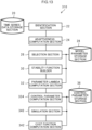
- a control parameter computation device 10 includes a time series data storage section 20, an identification section 22, an adaptiveness computation section 24, a selection section 26, a model parameter storage section 28, and a stability function builder 30.
- the control parameter computation device 10 also includes a parameter Lambda computation section 32, a control parameter computation section 34, and a control parameter storage section 36.
- the parameter Lambda computation section 32 is an example of a parameter computation section of the technology disclosed herein.
- the time series data storage section 20 is an example of a storage section of technology disclosed herein.
- Paired data is stored in the time series data storage section 20 representing pairs of time series data of an manipulated variable subject to control and time series data of a control variable with respect to the manipulated variable at each time.
- the paired data is divided into predetermined time segments, and the paired data for each of the time segments is stored in the time series data storage section 20.
- the paired data for each of the time segments is, for example, stored in the format of a table, as illustrated in Fig. 2 .
- the paired data for each of the time segments is data for change in dynamic response of a control variable y when an manipulated variable u subject to control is changed dynamically, and is data acquired as pairs of time series data for the manipulated variable u and time series data for the control variable y.
- Information about a change width of steps in the manipulated variable when the manipulated variable u is dynamically changed stepwise (in steps) is also stored as an manipulated variable change quantity du.
- An identification ID representing identification information of the paired data for each of the time segments, time series data for times t of the time segments, time series data of the manipulated variable, time series data of the control variable, and a scalar value of the manipulated variable change quantity for this time are stored associated with each other in the table illustrated in Fig. 2 .
- an identification ID 1 is stored in the example illustrated in Fig. 2 , associated with a time series data t1 vector, an manipulated variable time series data u1 vector, a control variable time series data y1 vector, and an manipulated variable change quantity du1 scalar value for this time.
- the system identification method may, for example, identify the model parameters such as the gain K, the time constants T, T 1 , T 2 , the dead time L, and the like using a prediction error method, a subspace identification method, or the like.
- Fig. 3 is an explanatory diagram to explain an identification method of the present embodiment.
- the identification section 22 identifies plural mathematical models of different structures using paired data A1 corresponding to a first time segment.
- the identification section 22 also identifies plural mathematical models of different structures using paired data B1 corresponding to another time segment.
- the identification section 22 also identifies plural mathematical models of different structures using paired data A2 corresponding to another time segment.
- the identification section 22 also identifies plural mathematical models of different structures using paired data B2 corresponding to another time segment. In this manner the identification section 22 identifies for all of the time segments plural mathematical models of different structures based on paired data corresponding to each of the time segments.
- the adaptiveness computation section 24 computes predicted values of the control variable with respect to the manipulated variables in the paired data by employing the respective paired data corresponding to time segments different to the time segment employed in identification.
- the adaptiveness computation section 24 then computes an adaptiveness representing the level of adaptation between the time series of the computed control variable predicted values, and the time series data of the control variable in the paired data corresponding to the time segments different to the time segment employed for identification.
- the adaptiveness computation section 24 employs the manipulated variable u in the paired data not employed in the identification to compute control variable predicted values y ⁇ according to Equation (3) below for time series using the mathematical models.
- the adaptiveness computation section 24 then computes an adaptiveness R 2 according to Equation (4) below for the control variable predicted value time series data y ⁇ i with respect to the control variable y time series data y i of the paired data not employed for identification.
- the adaptiveness R 2 is a coefficient of determination or a multiple correlation coefficient.
- Equation (4) i is an index of the time series data, and n indicates the total number of time segments. Note that a correlation coefficient, a Root Mean Square Error (RMSE), or the like may be employed for the adaptiveness.
- RMSE Root Mean Square Error
- the selection section 26 selects for each of the time segments a mathematical model for which the adaptiveness computed by the adaptiveness computation section 24 is greater than a predetermined threshold value for use as the mathematical model for the paired data of that time segment.
- the selection section 26 employs only a mathematical model having adaptiveness greater than the threshold value in order to eliminate mathematical models of low accuracy.
- the selection section 26 employs a mathematical model for which the adaptiveness computed by the adaptiveness computation section 24 is greater than the predetermined threshold value for single paired data of the manipulated variable u and the control variable y.
- the selection section 26 then stores information to identify the structure of the mathematical model employed for each of the time segments and model parameters thereof in the model parameter storage section 28.
- the information to identify the mathematical model selected by the selection section 26 for each of the time segments and the model parameters of the mathematical model are stored in the model parameter storage section 28.
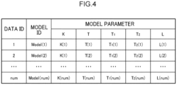
- the model parameters of the mathematical model selected for each of the time segments are, for example, stored in the format of a table as illustrated in Fig. 4 .
- Data IDs representing identification information of paired data for each of the time segments, model IDs representing identification information of the mathematical model selected for each of the time segments, and model parameters for the mathematical model are associated with each other and stored in the table illustrated in Fig. 4 .
- a data ID "1”, a model ID "model (1)”, and model parameters "K(1), T(1), T 1 (1), T 2 (1), and L(1)" are stored associated with each other in the example illustrated in Fig. 4 .
- the stability function builder 30 builds a stability function to compute the parameter Lambda in an internal control method. More specifically, the stability function builder 30 derives K p ( ⁇ ), T i , and T d using the internal model control method according to the mathematical model G p (s) for each of the time segments selected by the selection section 26 stored in the model parameter storage section 28.
- K p ( ⁇ ), T i , and T d are listed in Table 1 below.
- the stability function builder 30 builds a PID controller G c (s, ⁇ ) according to Equation (5) below based on the K p ( ⁇ ), T i , and T d computed according to the mathematical models G p (s) for each of the time segments.
- G c s ⁇ K p ⁇ 1 + 1 T i s + T d s
- the stability function builder 30 then employs the transfer function L (s, ⁇ ) to build a function g m ( ⁇ ) representing a gain margin of the transfer function L (s, ⁇ ) and a function p m ( ⁇ ) representing a phase margin of the transfer function L (s, ⁇ ), as represented by Equations (7) below.
- g m ⁇ ⁇ 20 log 10
- L jw pc ⁇ p m ⁇ 180 + ⁇ L jw gc ⁇
- w gc is a frequency such that the gain of transfer function L (s, ⁇ ) is 1.
- are symbols to indicate taking an absolute value of the content.
- the parameter Lambda computation section 32 Based on the respective mathematical models stored in the model parameter storage section 28 and selected for each of the time segments, the parameter Lambda computation section 32 computes parameter Lambda ⁇ , which is a parameter related to control parameters of a PID controller for each of these mathematical models.
- the parameter Lambda ⁇ is a parameter in the internal model control method.
- the parameter Lambda computation section 32 computes the parameter Lambda ⁇ of the internal model control method such that the function g m ( ⁇ ) representing the gain margin is a setting threshold value Gm th for the gain margin or greater, and such that the function p m ( ⁇ ) representing the phase margin is a setting threshold value Pm th for the phase margin or greater.
- the parameter Lambda computation section 32 also computes the parameter Lambda ⁇ according to Equation (8) so as to minimize a function expressed by a sum of a difference between the function g m ( ⁇ ) representing the gain margin and the gain margin setting threshold value Gm th added to a difference between the function p m ( ⁇ ) representing the phase margin and the phase margin setting threshold value Pm th .
- ⁇ opt arg min ⁇ Gm th ⁇ g m ⁇ + Pm th ⁇ p m ⁇
- optimization of the parameter Lambda ⁇ may be executed by employing an optimization algorithm such as a golden-section search method, a steepest descent method, Newton's method, an interior-point method, or a sequential quadratic programming method, or the like.
- the parameter Lambda ⁇ is increased gradually by predetermined increments from a value close to zero. This thereby enables a parameter Lambda ⁇ opt to be found such that the function g m ( ⁇ ) representing the gain margin is the gain margin setting threshold value Gm th or greater, and such that the function p m ( ⁇ ) representing the phase margin is the phase margin setting threshold value Pm th or greater.
- the control parameter computation section 34 computes control parameters in the PID controller based on the parameter Lambda ⁇ ⁇ pt computed by the parameter Lambda computation section 32.
- control parameter computation section 34 employs the optimized parameter Lambda ⁇ ⁇ pt and according to Equations (9) below, computes a proportional gain K p, opt , an integral gain K i, opt , and a differential gain K d, opt , which are the control parameters in each PID controller.
- control parameters in the PID controller computed by the control parameter computation section 34 which are the proportional gain K p, opt , the integral gain K i, opt , and the differential gain K d, opt , are stored in the control parameter storage section 36.
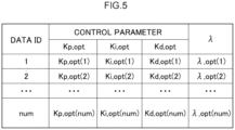
- control parameters of the PID controller and the parameter Lambda are, for example, stored in the format of a table, as illustrated in Fig. 5 .
- a data ID representing identification information of paired data and the control parameters are associated with each other and stored in the table illustrated in Fig. 5 .
- a data ID "1” For example, a data ID "1”, and control parameters "K p, opt (1), K i, opt (1), K d, opt (1) and ⁇ d, opt (1)" are associated with each other and stored in the example illustrated in Fig. 5 .
- control parameters K p, opt , K i, opt , and K d, opt in the PID controller are employed to control a control system that obtained the data stored in the time series data storage section 20.
- the control parameter computation device 10 may, for example, be implemented by a computer 50 illustrated in Fig. 6 .
- the computer 50 includes a CPU 51, memory 52 serving as a temporary storage area, and a non-volatile storage section 53.
- the computer 50 includes an input-output interface (I/F) 54 connected to an input-output device, and a read/write (R/W) section 55 to control reading and writing of data to and from a recording medium 59.
- the computer 50 includes a network I/F 56 connected to a network such as the Internet.
- the CPU 51, the memory 52, the storage section 53, the input-output I/F 54, the R/W section 55, and the network I/F 56 are mutually connected together through a bus 57.
- the storage section 53 may be realized by a hard disk drive (HDD), a solid state drive (SSD), a flash memory, or the like.
- a control parameter computation program 60 for causing the computer 50 to function as the control parameter computation device 10 is stored in the storage section 53 serving as a storage medium.
- the control parameter computation program 60 includes an identification process 61, an adaptiveness computation process 62, a selection process 63, a stability function build process 64, a parameter Lambda computation process 65, and a control parameter computation process 66.
- Information configuring the time series data storage section 20 is stored in a time series data storage region 67.
- Information configuring the model parameter storage section 28 is stored in a model parameter storage region 68.
- Information configuring the control parameter storage section 36 is stored in a control parameter storage region 69.
- the CPU 51 reads the control parameter computation program 60 from the storage section 53 and expands the control parameter computation program 60 in the memory 52. The CPU 51 then sequentially executes the processes of the control parameter computation program 60.
- the CPU 51 operates as the identification section 22 illustrated in Fig. 1 by executing the identification process 61.
- the CPU 51 operates as the adaptiveness computation section 24 illustrated in Fig. 1 by executing the adaptiveness computation process 62.
- the CPU 51 operates as the selection section 26 illustrated in Fig. 1 by executing the selection process 63.
- the CPU 51 operates as the stability function builder 30 illustrated in Fig. 1 by executing the stability function build process 64.
- the CPU 51 operates as the parameter Lambda computation section 32 illustrated in Fig. 1 by executing the parameter Lambda computation process 65.
- the CPU 51 operates as the control parameter computation section 34 illustrated in Fig. 1 by executing the control parameter computation process 66.
- the CPU 51 reads information from the time series data storage region 67 and expands the time series data storage section 20 into the memory 52.
- the CPU 51 reads information from the model parameter storage region 68 and expands the model parameter storage section 28 into the memory 52.
- the CPU 51 reads information from the control parameter storage region 69 and expands the control parameter storage section 36 into the memory 52.
- the computer 50 executing the control parameter computation program 60 thereby functions as the control parameter computation device 10.
- the CPU 51 is hardware for executing the control parameter computation program 60, which is software.
- control parameter computation program 60 may, for example, be implemented by a semiconductor integrated circuit, or more specifically by an application specific integrated circuit (ASIC) or the like.
- ASIC application specific integrated circuit
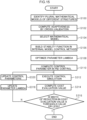
- control parameter computation device 10 On receipt of an instruction signal to compute control parameters, the control parameter computation device 10 executes a control parameter computation processing routine as illustrated in Fig. 7 .
- the adaptiveness computation section 24 computes, according to Equation (3), control variable predicted values time series data y ⁇ i using the manipulated variables u of the respective paired data not employed in the identification. Then at step S102, the adaptiveness computation section 24 computes, according to Equation (4), the adaptiveness R 2 for the control variable predicted values time series data y ⁇ i against the control variable y time series data y i of the paired data not employed in the identification.
- the selection section 26 selects for each of the time segments a mathematical model for which the adaptiveness computed at step S102 is greater than a predetermined threshold value as the mathematical model for the paired data of that time segment. Then at step S104, the selection section 26 stores the model parameters of the mathematical models for each of the time segments in the model parameter storage section 28.
- the stability function builder 30 derives K p ( ⁇ ), T i , and T d using the internal model control method according to the model parameters of the mathematical models G p (s) for each of the time segments stored in the model parameter storage section 28 at step S104.
- the stability function builder 30 builds the PID controller G c (s, ⁇ ) according to Equation (5) based on the K p ( ⁇ ), T i , and T d computed according to the mathematical models G p (s) for each of the time segments.
- the stability function builder 30 generates, according to Equation (6), the transfer function L (s, ⁇ ) represented by the product of the respective mathematical model G p (s) selected for each of the time segments multiplied by the PID controller G c (s, ⁇ ).
- the stability function builder 30 builds the function g m ( ⁇ ) representing the gain margin of the transfer function L (s, ⁇ ) and the function p m ( ⁇ ) representing the phase margin of the transfer function L (s, ⁇ ) as indicated in Equations (7).
- the parameter Lambda computation section 32 computes the parameter Lambda ⁇ ⁇ pt according to Equation (8) by gradually increasing the parameter Lambda ⁇ in predetermined increments from a value close to zero.
- the control parameter computation section 34 employs the parameter Lambda ⁇ ⁇ pt computed at step 5108 to compute the control parameters, which are the proportional gain K p, opt , the integral gain K i, opt , and the differential gain K d, opt , according to Equation (9).
- the control parameter computation section 34 then stores the proportional gain K p, opt , the integral gain K i, opt , and the differential gain K d, opt in the control parameter storage section 36 and ends processing.
- the control parameter computation device identifies for each of the time segments plural mathematical models of different structures using a system identification method based on the paired data corresponding to all of the time segments. Moreover, for each of the time segments and for each of the plural mathematical models identified for the respective time segments, the control parameter computation device uses the mathematical model to compute control variable predicted values with respect to the manipulated variables of the paired data for respective paired data corresponding to the time segments not employed in the identification. The control parameter computation device then computes the adaptiveness between the time series of the control variable predicted values, and the time series data for the control variable in the paired data corresponding to the time segments different to the time segment employed in the identification.
- the control parameter computation device selects for each of the time segments a mathematical model for which adaptiveness is greater than a predetermined threshold value as the mathematical model for the paired data of that time segment.
- the control parameter computation device then computes the parameter Lambda for the control parameters of the PID controller for the mathematical model based on the respective mathematical model selected for each of the time segments.
- the control parameter computation device then computes the control parameters in the PID controller based on the computed parameter Lambda. This accordingly enables the control parameters in the PID control to be efficiently estimated.
- the second embodiment differs from the first embodiment in the point that an interpolation map of control parameters for PID control is further produced.
- the same reference numerals are appended to portions configured similarly to the first embodiment and explanation thereof will be omitted.
- a control parameter computation device 210 includes a time series data storage section 20, an identification section 22, an adaptiveness computation section 24, a selection section 26, a model parameter storage section 28, and a stability function builder 30.
- the control parameter computation device 210 also includes a parameter Lambda computation section 32, a control parameter computation section 234, a control parameter storage section 236, and an interpolation map generator 238.
- the attribute information and the control parameters are stored in the control parameter storage section 236.
- the attribute information and the control parameters are, for example, stored in the format of a table, as illustrated in Fig. 9 .
- a data ID representing identification information for the paired data of each of the time segments, attribute information, and control parameters are associated with each other and stored in the table illustrated in Fig. 9 .
- a data ID "1”, attribute information "c1(1), c2(1), and c3(1)", and the control parameters which are proportional gain "K p, opt (1)", integral gain "K i, opt (1)", and differential gain "K d, opt (1)", are associated with each other and stored in the example illustrated in Fig. 9 .
- the interpolation map generator 238 Based on a combination of the attribute information and the control parameters stored in the control parameter storage section 236, the interpolation map generator 238 generates the interpolation map having attribute information and control parameters as axes, and interpolating a distribution of values of the attribute information and values of the control parameters.
- Fig. 10 illustrates an example of the interpolation map.
- the example illustrated in Fig. 10 is an example in which the attribute information is "difference between target value and control variable" and "rotation speed" in the system to be controlled, and an example of the control parameters is the proportional gain K p .
- each of the apexes on the interpolation map correspond to values computed by the control parameter computation section 234.
- each of the planes of the interpolation map correspond to values interpolated by the interpolation map generator 238.
- the attribute information may be any information as long as it is information obtainable when computing the control parameters. For example, by employing, as the attribute information, information about a change width of steps in the manipulated variable when the manipulated variable is dynamically changed stepwise (in steps), values of the control parameters can be referenced at higher precision.
- the control parameter computation device 210 may, for example, be realized by a computer 250 as illustrated in Fig. 11 .
- a control parameter computation program 260 to cause the computer 250 to function as the control parameter computation device 210 is stored in a storage section 53 serving as a storage medium.
- the control parameter computation program 260 includes an identification process 61, an adaptiveness computation process 62, a selection process 63, a stability function build process 64, and a parameter Lambda computation process 65.
- the control parameter computation program 260 also includes a control parameter computation process 266 and an interpolation map generation process 267.
- Information configuring the time series data storage section 20 is stored in a time series data storage region 67.
- Information configuring the model parameter storage section 28 is stored in a model parameter storage region 68.
- Information configuring the control parameter storage section 236 is stored in a control parameter storage region 269.
- a CPU 51 reads the control parameter computation program 260 from the storage section 53 and expands the control parameter computation program 260 in the memory 52.
- the CPU 51 then sequentially executes the processes of the control parameter computation program 260.
- the CPU 51 operates as the control parameter computation section 234 illustrated in Fig. 8 by executing the control parameter computation process 266.
- the CPU 51 operates as the interpolation map generator 238 illustrated in Fig. 8 by executing the interpolation map generation process 267.
- the CPU 51 reads information from the control parameter storage region 269 and expands the control parameter storage section 236 into the memory 52.
- Other processes are similar to those of the control parameter computation program 60 of the first embodiment.
- the computer 250 executing the control parameter computation program 260 thereby functions as the control parameter computation device 210.
- control parameter computation device 210 On receipt of an instruction signal to compute control parameters, the control parameter computation device 210 executes a control parameter computation processing routine illustrated in Fig. 12 .
- the interpolation map generator 238 Based on a combination of the attribute information and the control parameters stored in the control parameter storage section 236 at step S210, the interpolation map generator 238 generates at step S212 the interpolation map interpolating a distribution of values of the attribute information and values of the control parameters.
- the third embodiment differs from the first and the second embodiments in the point that, in control simulation, the control parameters are computed by repeatedly correcting the control parameters in consideration of an amount of overshoot from a target value or an amount of undershoot from a target value.
- the same reference numerals are appended to portions of configuration similar to that of the first and the second embodiments and explanation thereof will be omitted.
- a control parameter computation device 310 includes a time series data storage section 20, an identification section 22, an adaptiveness computation section 24, a selection section 26, a model parameter storage section 28, and a stability function builder 30.
- the control parameter computation device 310 also includes a parameter Lambda computation section 32, a control parameter computation section 334, a control parameter storage section 36, a simulation section 340, and a cost function computation section 342.
- the cost function computation section 342 computes a predetermined cost evaluation based on the results of control simulation obtained by the simulation section 340.
- a cost evaluation value J in the present embodiment includes an error evaluation value related to error between target value time series data and control variable time series data, a change evaluation value related to a change width in manipulated variable, and a penalty evaluation value related to an amount of overshoot from the target value or an amount of undershoot from the target value.
- Equation (10) the cost evaluation value J is represented by Equation (10) below.
- the cost evaluation value J includes an error evaluation value related to error between time series of a target value r trg and of a control variable y sim in the control simulation results.
- the cost evaluation value J also includes a penalty evaluation value of an amount ⁇ y sim, over of overshoot or undershoot from the target value in the control simulation results.
- the cost evaluation value J also includes a change evaluation value related to the width of change in the manipulated variable.
- the respective evaluation values are weighted by weighting coefficients Q err , R, Q over .
- t n is an end time of the control simulation
- t 0 is a start time of the control simulation.
- ⁇ u is a time change width of the manipulated variable.
- the control parameter computation device 310 may, for example, be realized by a computer 350 illustrated in Fig. 14 .
- a control parameter computation program 360 to cause the computer 350 to function as the control parameter computation device 310 is stored in the storage section 53 serving as a storage medium.
- the control parameter computation program 360 includes an identification process 61, an adaptiveness computation process 62, a selection process 63, a stability function build process 64, and a parameter Lambda computation process 65.
- the control parameter computation program 360 also includes a control parameter computation process 366, a simulation process 367, and a cost function computation process 368.
- Information configuring the time series data storage section 20 is stored in a time series data storage region 67.
- Information configuring the model parameter storage section 28 is stored in a model parameter storage region 68.
- Information configuring the control parameter storage section 36 is stored in the control parameter storage region 69.
- a CPU 51 reads the control parameter computation program 360 from the storage section 53 and expands the control parameter computation program 360 in the memory 52. The CPU 51 then sequentially executes the processes of the control parameter computation program 360.
- the CPU 51 operates as the control parameter computation section 334 illustrated in Fig. 13 by executing the control parameter computation process 366.
- the CPU 51 operates as the simulation section 340 illustrated in Fig. 13 by executing the simulation process 367.
- the CPU 51 operates as the cost function computation section 342 illustrated in Fig. 13 by executing the cost function computation process 368.
- the computer 350 executing the control parameter computation program 360 thereby functions as the control parameter computation device 310.
- control parameter computation device 310 On receipt of an instruction signal to compute control parameters, the control parameter computation device 310 executes a control parameter computation processing routine illustrated in Fig. 15 .
- the simulation section 340 sets the control parameter computed at step S 110 as an initial value when the repeated processing is being performed for the first time.
- the simulation section 340 then executes a control simulation on a system in which a PID controller set with the initial value and a plant model represented by a mathematical model are connected in a closed loop system structure.
- the control simulation is executed based on the control parameter updated at step S320 when the repeated processing is not being performed for the first time.
- the cost function computation section 342 computes the cost evaluation value J according to Equation (10) based on the control simulation results obtained at step S312.
- the cost function computation section 342 determines whether or not a reduction in width between the cost evaluation value J computed at step S314 this time and the cost evaluation value J computed at step S314 the previous time is a threshold value or smaller.
- the processing is ended when the reduction in width between the cost evaluation value J computed at step S314 this time and the cost evaluation value J computed at step S314 the previous time is the threshold value or smaller.
- the processing transitions to step S318 when the reduction in width between the cost evaluation value J computed at step S314 this time and the cost evaluation value J computed at step S314 the previous time is larger than the threshold value.
- the parameter Lambda computation section 32 updates the parameter Lambda so that the value of the function g m ( ⁇ ) representing the gain margin is the gain margin setting threshold value Gm th or greater, and so that the value of the function p m ( ⁇ ) representing the phase margin is the phase margin setting threshold value Pm th or greater.
- control parameter computation section 334 updates the control parameters based on the parameter Lambda updated at step S318.
- control parameter computation device executes control simulation on a system in which the PID controller set with initial values for the control parameters and the plant model represented by the mathematical model are connected in a closed loop system structure.
- the control parameter computation device then computes the control parameters by repeatedly correcting the control parameters until the reduction in width of the cost evaluation value is the predetermined threshold value or less. This thereby enables control parameters to be acquired for implementing PID control in which overshoot or undershoot has been suppressed from occurring.
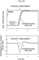
- the target for control in the present Example is an engine injection system for an automotive engine, and control results are compared for a control variable of a common rail pressure and an manipulated variable of a suction valve flow rate.
- a transfer function of a first order lag system is identified from time series data of an manipulated variable and a control variable, and control parameters for PID control are computed from information of steady-state gain, time constants, and dead time of the transfer function using a CHR method.
- Results of a comparison between control results using control parameters in PID control in a control parameter computation device according to the present embodiment and in a conventional method are illustrated in Fig. 16 .
- the line annotated with dots indicates the target value
- the dotted line indicates results using the control parameter computation device according to the present embodiment
- the solid line indicates results using the conventional method.
- the overshoot is smaller and the rise is also earlier in the control parameter computation device according to the present embodiment than in the conventional method, confirming that high control performance was achieved.
- work is needed to adjust the control parameters using trial and error in order to achieve performance at the same level as that in the control parameter computation device according to the present embodiment, resulting in a significant increase in workload.
- each of the programs is stored in advance (pre-installed) in a storage section there is no limitation thereto.
- the programs according to the technology disclosed herein may be provided in a form recorded on a recording medium, such as a CD-ROM, DVD-ROM, USB memory, or the like.
Landscapes
- Engineering & Computer Science (AREA)
- Physics & Mathematics (AREA)
- General Physics & Mathematics (AREA)
- Automation & Control Theory (AREA)
- Health & Medical Sciences (AREA)
- Artificial Intelligence (AREA)
- Computer Vision & Pattern Recognition (AREA)
- Evolutionary Computation (AREA)
- Medical Informatics (AREA)
- Software Systems (AREA)
- Feedback Control In General (AREA)
Claims (10)
- Steuerparameterberechnungsverfahren, umfassend:
durch einen Prozessor (51):Lesen (61) von geteilten, gepaarten Daten, die eine Paarung von Zeitseriendaten einer manipulierten Variablen darstellen, die Steuerung unterliegt, und von Zeitseriendaten einer Steuervariable in Bezug auf die manipulierte Variable zu jedem Zeitpunkt für jedes vorbestimmte Zeitsegment aus einem Speicherbereich (67), der die gepaarten Daten für jedes Zeitsegment speichert, und Identifizieren (61) für jedes Zeitsegment einer Vielzahl von mathematischen Modellen Gp(s) mit unterschiedlichen Strukturen basierend auf den dem Zeitsegment entsprechenden gepaarten Daten unter Verwendung eines Systemidentifizierungsverfahrens, wobei die Vielzahl von mathematischen Modellen mindestens zwei umfasst von: für jedes Zeitsegment und die Vielzahl von mathematischen Modellen, die für das Zeitsegment identifiziert wurden, Verwenden der mathematischen Modelle zum Berechnen (62) vorhergesagter Werte der Steuervariable in Bezug auf die manipulierte Variable in den gepaarten Daten für die jeweiligen gepaarten Daten, die unterschiedlichen Zeitsegmenten als dem zur Identifizierung verwendeten Zeitsegment entsprechen, und Berechnen (62) einer Anpassungsfähigkeit, die einen Anpassungsgrad zwischen einer Zeitserie der vorhergesagten Werte der berechneten Steuervariable und Zeitseriendaten der Steuervariable in den gepaarten Daten, die den Zeitsegmenten entsprechen, darstellt, die von dem für die Identifizierung verwendeten Zeitsegment unterschiedlich sind, wobei die Anpassungsfähigkeit ein Bestimmungskoeffizient oder ein Mehrfachkorrelationskoeffizient ist;für jedes Zeitsegment, Auswählen (63) als mathematisches Modell für die gepaarten Daten des Zeitsegments eines mathematischen Modells, für das die Anpassungsfähigkeit größer als ein vorbestimmter Schwellenwert ist;für jedes Zeitsegment, Konfigurieren (64) einer PID-Steuereinheit basierend auf einem internen Modellsteuerungsverfahren und auf dem jeweiligen ausgewählten mathematischen Modell, Erzeugen einer Transferfunktion, die durch ein Produkt der PID-Steuereinheit und des ausgewählten mathematischen Modells dargestellt ist, und Erzeugen (64) einer Funktion, die eine Verstärkungsspanne der Transferfunktion darstellt, und einer Funktion, die eine Phasenspanne der Transferfunktion darstellt; und Errichten einer Stabilitätsfunktion, um den Parameter Lambda in einem internen Steuerungsverfahren (65) so zu berechnen, dass die Funktion, die die Verstärkungsspanne darstellt, gleich groß oder größer ist als ein die Verstärkungsspanne festlegender Schwellenwert, und die Funktion, die die Phasenspanne darstellt, gleich groß oder größer ist als ein die Phasenspanne festlegender Schwellenwert, und um eine Funktion zu minieren, die durch eine Summe einer Differenz zwischen der Funktion, die die Verstärkungsspanne darstellt, und dem die Verstärkungsspanne festlegenden Schwellenwert addiert zu einer Differenz zwischen der Funktion, die die Phasenspanne darstellt, und dem die Phasenspanne festlegenden Schwellenwert dargestellt ist, und dann Berechnen (66) der Steuerparameter Kp(λ), Ti, Td in der PID-Steuereinheit
 unter Verwendung des internen Modellsteuerungsverfahrens gemäß dem mathematischen Modell Gp (s) für jedes der Zeitsegmente gemäß der Liste von Berechnungsgleichungen für die PID-Parameter Kp(λ), Ti und Ta in Abhängigkeit von dem mathematischen Modell Gp (s) der nachstehenden Tabelle:
Struktur des mathematischen Modells Kp (λ) Ti Td 

T - 


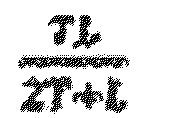


T 1 + T 2 

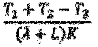
T 1 + T 2 - T 3  der Parameter Lambda als ein anfänglicher Wert der PID-Steuereinheit eingestellt wird und eine Steuerungssimulation auf einem System ausgeführt wird, in dem eine PID-Steuereinheit, die mit dem anfänglichen Wert eingestellt ist, und ein Anlagenmodell, das durch das mathematische Modell dargestellt ist, durch eine Struktur mit geschlossenem Kreislauf verbunden sind;der Steuerparameter durch wiederholtes Korrigieren des Parameters Lambda berechnet wird, bis eine Verringerungsbreite in einem Kostenbeurteilungswert ein vorbestimmter Schwellenwert oder weniger ist, der Kostenbeurteilungswert einen Fehlerbeurteilungswert einschließt, der sich auf einen Fehler zwischen Zeitseriendaten eines Zielwerts und Zeitseriendaten einer Steuervariablen in Ergebnissen der Steuerungssimulation bezieht, und einen Abzugsbeurteilungswert einschließt, der sich auf ein Ausmaß von Überschreiten des Zielwerts oder ein Ausmaß von Unterschreiten des Zielwerts in den Steuerungssimulationsergebnissen bezieht; undder Kostenbeurteilungswert weiter einen Änderungsbeurteilungswert einschließt, der sich auf eine Änderungsbreite der manipulierten Variable bezieht,wobei der Steuerparameter zum Steuern eines Steuersystems verwendet wird, von dem die Zeitseriendaten erhalten werden.
 - Steuerparameterberechnungsverfahren nach Anspruch 1, wobei
basierend auf einer Kombination von Attributinformationen, die ein Attribut darstellen, wenn der Steuerparameter berechnet wird, und basierend auf dem Steuerparameter eine Interpolationskarte erzeugt wird, die die Attributinformationen und den Steuerparameter als Achsen aufweist und eine Werteverteilung der Attributinformationen und Werte des Steuerparameters interpoliert. - Steuerparameterberechnungsverfahren nach Anspruch 2, wobei die Attributinformationen eine Änderungsbreite der manipulierten Variable sind.
- Steuerparameterberechnungsverfahren nach Anspruch 1, wobei
jeder in dem Kostenbeurteilungswert eingeschlossene Beurteilungswert durch einen voreingestellten Wert gewichtet wird. - Steuerparameterberechnungsverfahren nach einem der Ansprüche 1 bis Anspruch 4, wobei
beim Berechnen des Parameters Lambda der Parameter Lambda durch wiederholtes Erhöhen des Parameters Lambda berechnet wird, bis ein Wert der Funktion, die die Verstärkungsspanne darstellt, gleich groß oder größer ist als der die Verstärkungsspanne festlegende Schwellenwert, und ein Wert der Funktion, die die Phasenspanne darstellt, gleich groß oder größer ist als der die Phasenspanne festlegende Schwellenwert. - Steuerparameterberechnungsverfahren nach einem der Ansprüche 1 bis Anspruch 5, wobei
das Subjekt von Steuerung ein Dieselmotor ist, wobei die manipulierte Variable eine Einspritzmenge eines Injektors ist und die Steuervariable eine Temperatur am Eingangsanschluss eines Dieselpartikelfilters ist. - Steuerparameterberechnungsvorrichtung (10), umfassend:einen Identifizierungsabschnitt (22), der konfiguriert ist zum Lesen von geteilten, gepaarten Daten, die eine Paarung von Zeitseriendaten einer manipulierten Variablen darstellen, die Steuerung unterliegt, und von Zeitseriendaten einer Steuervariable in Bezug auf die manipulierte Variable zu jedem Zeitpunkt für jedes vorbestimmte Zeitsegment aus einem Speicherbereich, der die gepaarten Daten für jedes Zeitsegment speichert, und Identifizieren für jedes Zeitsegment einer Vielzahl von mathematischen Modellen Gp(s) mit unterschiedlichen Strukturen basierend auf den dem Zeitsegment entsprechenden gepaarten Daten unter Verwendung eines Systemidentifizierungsverfahrens, wobei die Vielzahl von mathematischen Modellen mindestens zwei umfasst von:
 einen Anpassungsfähigkeits-Berechnungsabschnitt (24), der so konfiguriert ist, dass er für jedes Zeitsegment und die Vielzahl von mathematischen Modellen, die für das Zeitsegment identifiziert wurden, die mathematischen Modelle verwendet zum Berechnen vorhergesagter Werte der Steuervariable in Bezug auf die manipulierte Variable in den gepaarten Daten für die jeweiligen gepaarten Daten, die unterschiedlichen Zeitsegmenten als dem zur Identifizierung verwendeten Zeitsegment entsprechen, und Berechnen einer Anpassungsfähigkeit zwischen einer Zeitserie der vorhergesagten Werte der berechneten Steuervariable und Zeitseriendaten der Steuervariable in den gepaarten Daten, die den Zeitsegmenten entsprechen, die von dem für die Identifizierung verwendeten Zeitsegment unterschiedlich sind, wobei die Anpassungsfähigkeit ein Bestimmungskoeffizient oder ein Mehrfachkorrelationskoeffizient ist;einen Auswahlabschnitt (26), der so konfiguriert ist, dass er für jedes Zeitsegment als mathematisches Modell für die gepaarten Daten des Zeitsegments ein mathematisches Modell auswählt, für das die Anpassungsfähigkeit größer ist als ein vorbestimmter Schwellenwert;einen Stabilitätsfunktionsersteller (30), der so konfiguriert ist, dass er für jedes Zeitsegment basierend auf einem internen Modellsteuerungsverfahren und auf dem jeweiligen ausgewählten mathematischen Modell eine PID-Steuereinheit konfiguriert, eine Transferfunktion erzeugt, die durch ein Produkt der PID-Steuereinheit und des ausgewählten mathematischen Modells dargestellt ist, und eine Funktion, die einen Verstärkungsspanne der Transferfunktion darstellt, und eine Funktion, die eine Phasenspanne der Transferfunktion darstellt, erzeugt; undeinen Berechnungsabschnitt (32) des Parameters Lambda, der so konfiguriert ist, dass er einen Parameter Lambda in dem internen Modellsteuerungsverfahren so berechnet, dass die Funktion, die die Verstärkungsspanne darstellt, gleich groß oder größer ist als ein die Verstärkungsspanne festlegender Schwellenwert, und die Funktion, die die Phasenspanne darstellt, gleich groß oder größer ist als ein die Phasenspanne festlegender Schwellenwert, und um eine Funktion zu minieren, die durch eine Summe einer Differenz zwischen der Funktion, die die Verstärkungsspanne darstellt, und dem die Verstärkungsspanne festlegenden Schwellenwert addiert zu einer Differenz zwischen der Funktion, die die Phasenspanne darstellt, und dem die Phasenspanne festlegenden Schwellenwert dargestellt ist; undeinen Steuerparameterberechnungsabschnitt (34), der so konfiguriert ist, dass er den Steuerparameter Kp(λ), Ti, Td in der PID-Steuereinheit berechnet
Struktur des mathematischen Modells Kp (λ) Ti Td 

T - 





T 1 + T 2 
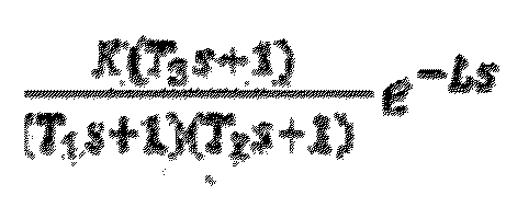

T 1 + T 2 - T 3  der Parameter Lambda als ein anfänglicher Wert der PID-Steuereinheit eingestellt wird und eine Steuerungssimulation auf einem System ausgeführt wird, in dem eine PID-Steuereinheit, die mit dem anfänglichen Wert eingestellt ist, und ein Anlagenmodell, das durch das mathematische Modell dargestellt ist, durch eine Struktur mit geschlossenem Kreislauf verbunden sind;der Steuerparameter durch wiederholtes Korrigieren des Parameters Lambda berechnet wird, bis eine Verringerungsbreite in einem Kostenbeurteilungswert ein vorbestimmter Schwellenwert oder weniger ist, der Kostenbeurteilungswert einen Fehlerbeurteilungswert einschließt, der sich auf einen Fehler zwischen Zeitseriendaten eines Zielwerts und Zeitseriendaten einer Steuervariablen in Ergebnissen der Steuerungssimulation bezieht, und einen Abzugsbeurteilungswert einschließt, der sich auf ein Ausmaß von Überschreiten des Zielwerts oder ein Ausmaß von Unterschreiten des Zielwerts in den Steuerungssimulationsergebnissen bezieht; undder Kostenbeurteilungswert weiter einen Änderungsbeurteilungswert einschließt, der sich auf eine Änderungsbreite der manipulierten Variable bezieht,wobei der Steuerparameter zum Steuern eines Steuersystems verwendet wird, von dem die Zeitseriendaten erhalten werden.
 - Steuerparameterberechnungsvorrichtung (210) nach Anspruch 7, weiter umfassend:
einen Interpolationskartenerzeuger (238), der so konfiguriert ist, dass er basierend auf einer Kombination von Attributinformationen, die ein Attribut darstellen, wenn der Steuerparameter berechnet wird, und basierend auf dem Steuerparameter eine Interpolationskarte erzeugt, die die Attributinformationen und den Steuerparameter als Achsen aufweist und eine Werteverteilung der Attributinformationen und Werte des Steuerparameters interpoliert. - Steuerparameterberechnungsvorrichtung (210) nach Anspruch 8, wobei:
die Attributinformationen eine Änderungsbreite der manipulierten Variable sind. - Steuerparameterberechnungsprogramm (60), umfassend Anweisungen, die, wenn sie von einer Steuerparameterberechnungsvorrichtung nach einem der Ansprüche 7 bis 9 ausgeführt werden, bewirken, dass die Steuerparameterberechnungsvorrichtung ein Verfahren nach einem der Ansprüche 1 bis 6 durchführt.
Applications Claiming Priority (1)
| Application Number | Priority Date | Filing Date | Title |
|---|---|---|---|
| JP2018097379A JP7095834B2 (ja) | 2018-05-21 | 2018-05-21 | 制御パラメータ計算方法、制御パラメータ計算プログラム、及び制御パラメータ計算装置 |
Publications (2)
| Publication Number | Publication Date |
|---|---|
| EP3575893A1 EP3575893A1 (de) | 2019-12-04 |
| EP3575893B1 true EP3575893B1 (de) | 2024-10-02 |
Family
ID=66676178
Family Applications (1)
| Application Number | Title | Priority Date | Filing Date |
|---|---|---|---|
| EP19175099.1A Active EP3575893B1 (de) | 2018-05-21 | 2019-05-17 | Steuerparameterberechnungsverfahren und steuerparameterberechnungsvorrichtung |
Country Status (3)
| Country | Link |
|---|---|
| US (1) | US10859987B2 (de) |
| EP (1) | EP3575893B1 (de) |
| JP (1) | JP7095834B2 (de) |
Families Citing this family (9)
| Publication number | Priority date | Publication date | Assignee | Title |
|---|---|---|---|---|
| KR102225315B1 (ko) * | 2019-06-03 | 2021-03-10 | 재단법인대구경북과학기술원 | 시스템 제어 장치 및 방법 |
| JP7788921B2 (ja) | 2022-04-11 | 2025-12-19 | オークマ株式会社 | 負荷装置の位置による特性変動を考慮したパラメータ調整装置および方法 |
| CN114900616B (zh) * | 2022-07-14 | 2022-10-28 | 四川三思德科技有限公司 | 一种用于光伏摄像头的直流电机驱动装置及方法 |
| CN115826632B (zh) * | 2022-10-21 | 2025-08-22 | 广西防城港核电有限公司 | 基于arx的水位控制系统整定值优化方法及存储介质 |
| JP7800387B2 (ja) * | 2022-11-11 | 2026-01-16 | 横河電機株式会社 | 装置、方法およびプログラム |
| US12149419B1 (en) * | 2023-06-23 | 2024-11-19 | International Business Machines Corporation | Benchmarking and prediction of cloud system performance |
| CN118605148B (zh) * | 2024-05-15 | 2025-10-21 | 清华大学 | 基于广义逆运算的水轮机调速方法、装置、系统及介质 |
| CN119758924B (zh) * | 2024-12-26 | 2025-07-15 | 北京中环信科科技股份有限公司 | 一种炼化装置参数控制方法、装置和设备 |
| CN121057114B (zh) * | 2025-11-04 | 2026-01-27 | 苏州晟丰电子科技有限公司 | 一种一体式真空塞孔机填塞控制方法及系统 |
Family Cites Families (24)
| Publication number | Priority date | Publication date | Assignee | Title |
|---|---|---|---|---|
| JPH08110802A (ja) * | 1994-10-12 | 1996-04-30 | Yamatake Honeywell Co Ltd | Pidコントローラ |
| JPH08161004A (ja) * | 1994-12-09 | 1996-06-21 | Toshiba Corp | Pidコントローラ |
| US7058617B1 (en) * | 1996-05-06 | 2006-06-06 | Pavilion Technologies, Inc. | Method and apparatus for training a system model with gain constraints |
| US6278899B1 (en) * | 1996-05-06 | 2001-08-21 | Pavilion Technologies, Inc. | Method for on-line optimization of a plant |
| JP3592519B2 (ja) * | 1997-09-16 | 2004-11-24 | 本田技研工業株式会社 | 内燃機関の排気系の空燃比制御装置及びプラントの制御装置 |
| US7113834B2 (en) * | 2000-06-20 | 2006-09-26 | Fisher-Rosemount Systems, Inc. | State based adaptive feedback feedforward PID controller |
| JP3864781B2 (ja) * | 2001-12-28 | 2007-01-10 | オムロン株式会社 | 温度調節器 |
| JP2005122542A (ja) * | 2003-10-17 | 2005-05-12 | Toshiba Corp | 非線形プロセス制御装置 |
| JP4536666B2 (ja) * | 2006-02-13 | 2010-09-01 | 出光興産株式会社 | Pid制御器の最適調整システム及び最適調整方法 |
| ATE538417T1 (de) | 2006-05-19 | 2012-01-15 | Siemens Industry Inc | Automatische einstellung eines geschlossenen regelkreises |
| JP2009116515A (ja) * | 2007-11-05 | 2009-05-28 | Fuji Electric Systems Co Ltd | Pidパラメータ調節支援装置 |
| US8185217B2 (en) * | 2008-01-31 | 2012-05-22 | Fisher-Rosemount Systems, Inc. | Robust adaptive model predictive controller with tuning to compensate for model mismatch |
| US8260440B2 (en) * | 2008-12-05 | 2012-09-04 | The Regents Of The University Of Michigan | Adaptive control based on retrospective cost optimization |
| US8200346B2 (en) * | 2009-02-02 | 2012-06-12 | Fisher-Rosemount Systems, Inc. | Model predictive controller with tunable integral component to compensate for model mismatch |
| JP2011063130A (ja) | 2009-09-17 | 2011-03-31 | Jtekt Corp | 制御パラメータ適合装置 |
| JP5749041B2 (ja) | 2011-03-04 | 2015-07-15 | 株式会社竹中工務店 | アクティブフィードバック制御装置及びプログラム |
| US9102209B2 (en) * | 2012-06-27 | 2015-08-11 | Bose Corporation | Anti-causal vehicle suspension |
| JP2014048715A (ja) * | 2012-08-29 | 2014-03-17 | Toyota Motor Corp | プラント制御装置 |
| US9206751B2 (en) * | 2013-06-25 | 2015-12-08 | Achates Power, Inc. | Air handling control for opposed-piston engines with uniflow scavenging |
| WO2015015876A1 (ja) * | 2013-07-29 | 2015-02-05 | 三菱電機株式会社 | 制御装置 |
| DE112015001832A5 (de) * | 2014-04-16 | 2016-12-29 | Schaeffler Technologies AG & Co. KG | Verfahren zur Auslegung eines Softwaretilgers einer Kupplungssteuerung und Softwaretilger zur Dämpfung von Rupfschwingungen |
| US10545482B2 (en) * | 2014-07-23 | 2020-01-28 | Honeywell International Inc. | Robust control design approach for chemical processing industries and other industries |
| US10534325B2 (en) * | 2016-07-14 | 2020-01-14 | Honeywell International Inc. | Adaptive control techniques for pH control or control of other industrial processes |
| US20190090209A1 (en) * | 2017-09-20 | 2019-03-21 | Wilson Electronics, Llc | Oscillation mitigation using successive approximation in a signal booster |
-
2018
- 2018-05-21 JP JP2018097379A patent/JP7095834B2/ja active Active
-
2019
- 2019-05-16 US US16/414,647 patent/US10859987B2/en active Active
- 2019-05-17 EP EP19175099.1A patent/EP3575893B1/de active Active
Non-Patent Citations (1)
| Title |
|---|
| DONG HWA KIM: "Tuning of PID controller using gain/phase margin and immune algorithm", SOFT COMPUTING IN INDUSTRIAL APPLICATIONS, 2005. SMCIA/05. PROCEEDINGS OF THE 2005 IEEE MIDNIGHT-SUMMER WORKSHOP ON ESPOO, FINLAND JUNE 28-30, 2005, PISCATAWAY, NJ, USA,IEEE, 28 June 2005 (2005-06-28), pages 69 - 74, XP010814654, ISBN: 978-0-7803-8942-7 * |
Also Published As
| Publication number | Publication date |
|---|---|
| JP2019204178A (ja) | 2019-11-28 |
| EP3575893A1 (de) | 2019-12-04 |
| US10859987B2 (en) | 2020-12-08 |
| US20190354072A1 (en) | 2019-11-21 |
| JP7095834B2 (ja) | 2022-07-05 |
Similar Documents
| Publication | Publication Date | Title |
|---|---|---|
| EP3575893A1 (de) | Steuerparameterberechnungsverfahren und steuerparameterberechnungsvorrichtung | |
| JP2004503000A (ja) | 多変量マトリクスプロセス制御 | |
| JP4223894B2 (ja) | Pidパラメータ調整装置 | |
| US7949415B2 (en) | Apparatus and method for model-based control for integrating processes | |
| EP2392979A2 (de) | Multivariable modellbasierte prädiktive Regelung | |
| US7970482B2 (en) | Method and system for process control | |
| CN103718118B (zh) | 自适应控制装置及自适应控制方法及注射成型机的控制装置及控制方法 | |
| US20180267486A1 (en) | Control device, storage medium, and control system | |
| CN108919639B (zh) | 一种pid控制器参数最优比例模型建立方法 | |
| JP6380552B2 (ja) | 制御装置、そのプログラム、プラント制御方法 | |
| US11226599B2 (en) | Machine learning system, control device, and machine learning method for optimizing filter coefficients | |
| Dey et al. | A simple nonlinear PD controller for integrating processes | |
| JP2003195905A (ja) | 制御装置および温度調節器 | |
| US20230324885A1 (en) | Control assistance device, control system, and control assistance method | |
| CN112748660A (zh) | 存储器、加热炉出口温度控制方法、装置和设备 | |
| JP4825960B2 (ja) | 制御装置、制御パラメータの調整装置、制御パラメータの調整方法 | |
| CN115981159A (zh) | 基于模型辅助和类史密斯预估的广义改进自抗扰控制方法 | |
| JP2005284828A (ja) | 制御装置、制御パラメータの調整方法、プログラムおよび記録媒体 | |
| JP6833133B1 (ja) | 制御装置、制御システム、制御方法及びプログラム | |
| CN115502977B (zh) | 机械臂随动控制方法、装置、机械臂及存储介质 | |
| Xu et al. | Enhancing trajectory tracking for a class of process control problems using iterative learning | |
| JP2005339004A (ja) | 制御装置、制御パラメータの調整装置、制御パラメータの調整方法、プログラムおよび記録媒体 | |
| CN116954085A (zh) | 一种基于预设性能函数的二阶滑模控制方法、装置及设备 | |
| CN117130271A (zh) | 一种基于时滞系统的反馈控制器设计方法 | |
| de Castro et al. | Unrestricted horizon predictive control applied to a nonlinear SISO system: LAM de Castro et al. |
Legal Events
| Date | Code | Title | Description |
|---|---|---|---|
| PUAI | Public reference made under article 153(3) epc to a published international application that has entered the european phase |
Free format text: ORIGINAL CODE: 0009012 |
|
| STAA | Information on the status of an ep patent application or granted ep patent |
Free format text: STATUS: THE APPLICATION HAS BEEN PUBLISHED |
|
| AK | Designated contracting states |
Kind code of ref document: A1 Designated state(s): AL AT BE BG CH CY CZ DE DK EE ES FI FR GB GR HR HU IE IS IT LI LT LU LV MC MK MT NL NO PL PT RO RS SE SI SK SM TR |
|
| AX | Request for extension of the european patent |
Extension state: BA ME |
|
| STAA | Information on the status of an ep patent application or granted ep patent |
Free format text: STATUS: REQUEST FOR EXAMINATION WAS MADE |
|
| 17P | Request for examination filed |
Effective date: 20200518 |
|
| RBV | Designated contracting states (corrected) |
Designated state(s): AL AT BE BG CH CY CZ DE DK EE ES FI FR GB GR HR HU IE IS IT LI LT LU LV MC MK MT NL NO PL PT RO RS SE SI SK SM TR |
|
| STAA | Information on the status of an ep patent application or granted ep patent |
Free format text: STATUS: EXAMINATION IS IN PROGRESS |
|
| 17Q | First examination report despatched |
Effective date: 20211111 |
|
| GRAP | Despatch of communication of intention to grant a patent |
Free format text: ORIGINAL CODE: EPIDOSNIGR1 |
|
| STAA | Information on the status of an ep patent application or granted ep patent |
Free format text: STATUS: GRANT OF PATENT IS INTENDED |
|
| INTG | Intention to grant announced |
Effective date: 20240610 |
|
| RAP3 | Party data changed (applicant data changed or rights of an application transferred) |
Owner name: TRANSTRON INC. |
|
| GRAS | Grant fee paid |
Free format text: ORIGINAL CODE: EPIDOSNIGR3 |
|
| GRAA | (expected) grant |
Free format text: ORIGINAL CODE: 0009210 |
|
| STAA | Information on the status of an ep patent application or granted ep patent |
Free format text: STATUS: THE PATENT HAS BEEN GRANTED |
|
| AK | Designated contracting states |
Kind code of ref document: B1 Designated state(s): AL AT BE BG CH CY CZ DE DK EE ES FI FR GB GR HR HU IE IS IT LI LT LU LV MC MK MT NL NO PL PT RO RS SE SI SK SM TR |
|
| REG | Reference to a national code |
Ref country code: GB Ref legal event code: FG4D |
|
| REG | Reference to a national code |
Ref country code: CH Ref legal event code: EP |
|
| REG | Reference to a national code |
Ref country code: IE Ref legal event code: FG4D |
|
| REG | Reference to a national code |
Ref country code: DE Ref legal event code: R096 Ref document number: 602019059654 Country of ref document: DE |
|
| REG | Reference to a national code |
Ref country code: LT Ref legal event code: MG9D |
|
| REG | Reference to a national code |
Ref country code: NL Ref legal event code: MP Effective date: 20241002 |
|
| REG | Reference to a national code |
Ref country code: AT Ref legal event code: MK05 Ref document number: 1728923 Country of ref document: AT Kind code of ref document: T Effective date: 20241002 |
|
| PG25 | Lapsed in a contracting state [announced via postgrant information from national office to epo] |
Ref country code: NL Free format text: LAPSE BECAUSE OF FAILURE TO SUBMIT A TRANSLATION OF THE DESCRIPTION OR TO PAY THE FEE WITHIN THE PRESCRIBED TIME-LIMIT Effective date: 20241002 |
|
| PG25 | Lapsed in a contracting state [announced via postgrant information from national office to epo] |
Ref country code: NL Free format text: LAPSE BECAUSE OF FAILURE TO SUBMIT A TRANSLATION OF THE DESCRIPTION OR TO PAY THE FEE WITHIN THE PRESCRIBED TIME-LIMIT Effective date: 20241002 |
|
| PG25 | Lapsed in a contracting state [announced via postgrant information from national office to epo] |
Ref country code: PT Free format text: LAPSE BECAUSE OF FAILURE TO SUBMIT A TRANSLATION OF THE DESCRIPTION OR TO PAY THE FEE WITHIN THE PRESCRIBED TIME-LIMIT Effective date: 20250203 Ref country code: HR Free format text: LAPSE BECAUSE OF FAILURE TO SUBMIT A TRANSLATION OF THE DESCRIPTION OR TO PAY THE FEE WITHIN THE PRESCRIBED TIME-LIMIT Effective date: 20241002 Ref country code: IS Free format text: LAPSE BECAUSE OF FAILURE TO SUBMIT A TRANSLATION OF THE DESCRIPTION OR TO PAY THE FEE WITHIN THE PRESCRIBED TIME-LIMIT Effective date: 20250202 |
|
| PG25 | Lapsed in a contracting state [announced via postgrant information from national office to epo] |
Ref country code: FI Free format text: LAPSE BECAUSE OF FAILURE TO SUBMIT A TRANSLATION OF THE DESCRIPTION OR TO PAY THE FEE WITHIN THE PRESCRIBED TIME-LIMIT Effective date: 20241002 |
|
| PG25 | Lapsed in a contracting state [announced via postgrant information from national office to epo] |
Ref country code: BG Free format text: LAPSE BECAUSE OF FAILURE TO SUBMIT A TRANSLATION OF THE DESCRIPTION OR TO PAY THE FEE WITHIN THE PRESCRIBED TIME-LIMIT Effective date: 20241002 |
|
| PG25 | Lapsed in a contracting state [announced via postgrant information from national office to epo] |
Ref country code: ES Free format text: LAPSE BECAUSE OF FAILURE TO SUBMIT A TRANSLATION OF THE DESCRIPTION OR TO PAY THE FEE WITHIN THE PRESCRIBED TIME-LIMIT Effective date: 20241002 |
|
| PG25 | Lapsed in a contracting state [announced via postgrant information from national office to epo] |
Ref country code: NO Free format text: LAPSE BECAUSE OF FAILURE TO SUBMIT A TRANSLATION OF THE DESCRIPTION OR TO PAY THE FEE WITHIN THE PRESCRIBED TIME-LIMIT Effective date: 20250102 |
|
| PG25 | Lapsed in a contracting state [announced via postgrant information from national office to epo] |
Ref country code: AT Free format text: LAPSE BECAUSE OF FAILURE TO SUBMIT A TRANSLATION OF THE DESCRIPTION OR TO PAY THE FEE WITHIN THE PRESCRIBED TIME-LIMIT Effective date: 20241002 Ref country code: LV Free format text: LAPSE BECAUSE OF FAILURE TO SUBMIT A TRANSLATION OF THE DESCRIPTION OR TO PAY THE FEE WITHIN THE PRESCRIBED TIME-LIMIT Effective date: 20241002 Ref country code: GR Free format text: LAPSE BECAUSE OF FAILURE TO SUBMIT A TRANSLATION OF THE DESCRIPTION OR TO PAY THE FEE WITHIN THE PRESCRIBED TIME-LIMIT Effective date: 20250103 |
|
| PG25 | Lapsed in a contracting state [announced via postgrant information from national office to epo] |
Ref country code: CZ Free format text: LAPSE BECAUSE OF FAILURE TO SUBMIT A TRANSLATION OF THE DESCRIPTION OR TO PAY THE FEE WITHIN THE PRESCRIBED TIME-LIMIT Effective date: 20241002 Ref country code: PL Free format text: LAPSE BECAUSE OF FAILURE TO SUBMIT A TRANSLATION OF THE DESCRIPTION OR TO PAY THE FEE WITHIN THE PRESCRIBED TIME-LIMIT Effective date: 20241002 |
|
| PGFP | Annual fee paid to national office [announced via postgrant information from national office to epo] |
Ref country code: FR Payment date: 20250326 Year of fee payment: 7 |
|
| PG25 | Lapsed in a contracting state [announced via postgrant information from national office to epo] |
Ref country code: RS Free format text: LAPSE BECAUSE OF FAILURE TO SUBMIT A TRANSLATION OF THE DESCRIPTION OR TO PAY THE FEE WITHIN THE PRESCRIBED TIME-LIMIT Effective date: 20250102 |
|
| PG25 | Lapsed in a contracting state [announced via postgrant information from national office to epo] |
Ref country code: SM Free format text: LAPSE BECAUSE OF FAILURE TO SUBMIT A TRANSLATION OF THE DESCRIPTION OR TO PAY THE FEE WITHIN THE PRESCRIBED TIME-LIMIT Effective date: 20241002 |
|
| REG | Reference to a national code |
Ref country code: DE Ref legal event code: R097 Ref document number: 602019059654 Country of ref document: DE |
|
| PGFP | Annual fee paid to national office [announced via postgrant information from national office to epo] |
Ref country code: DE Payment date: 20250324 Year of fee payment: 7 |
|
| PG25 | Lapsed in a contracting state [announced via postgrant information from national office to epo] |
Ref country code: DK Free format text: LAPSE BECAUSE OF FAILURE TO SUBMIT A TRANSLATION OF THE DESCRIPTION OR TO PAY THE FEE WITHIN THE PRESCRIBED TIME-LIMIT Effective date: 20241002 |
|
| PG25 | Lapsed in a contracting state [announced via postgrant information from national office to epo] |
Ref country code: EE Free format text: LAPSE BECAUSE OF FAILURE TO SUBMIT A TRANSLATION OF THE DESCRIPTION OR TO PAY THE FEE WITHIN THE PRESCRIBED TIME-LIMIT Effective date: 20241002 |
|
| PG25 | Lapsed in a contracting state [announced via postgrant information from national office to epo] |
Ref country code: RO Free format text: LAPSE BECAUSE OF FAILURE TO SUBMIT A TRANSLATION OF THE DESCRIPTION OR TO PAY THE FEE WITHIN THE PRESCRIBED TIME-LIMIT Effective date: 20241002 |
|
| PG25 | Lapsed in a contracting state [announced via postgrant information from national office to epo] |
Ref country code: SK Free format text: LAPSE BECAUSE OF FAILURE TO SUBMIT A TRANSLATION OF THE DESCRIPTION OR TO PAY THE FEE WITHIN THE PRESCRIBED TIME-LIMIT Effective date: 20241002 |
|
| PG25 | Lapsed in a contracting state [announced via postgrant information from national office to epo] |
Ref country code: IT Free format text: LAPSE BECAUSE OF FAILURE TO SUBMIT A TRANSLATION OF THE DESCRIPTION OR TO PAY THE FEE WITHIN THE PRESCRIBED TIME-LIMIT Effective date: 20241002 |
|
| PLBE | No opposition filed within time limit |
Free format text: ORIGINAL CODE: 0009261 |
|
| STAA | Information on the status of an ep patent application or granted ep patent |
Free format text: STATUS: NO OPPOSITION FILED WITHIN TIME LIMIT |
|
| PG25 | Lapsed in a contracting state [announced via postgrant information from national office to epo] |
Ref country code: SE Free format text: LAPSE BECAUSE OF FAILURE TO SUBMIT A TRANSLATION OF THE DESCRIPTION OR TO PAY THE FEE WITHIN THE PRESCRIBED TIME-LIMIT Effective date: 20241002 |
|
| 26N | No opposition filed |
Effective date: 20250703 |
|
| REG | Reference to a national code |
Ref country code: CH Ref legal event code: H13 Free format text: ST27 STATUS EVENT CODE: U-0-0-H10-H13 (AS PROVIDED BY THE NATIONAL OFFICE) Effective date: 20251223 |
|
| PG25 | Lapsed in a contracting state [announced via postgrant information from national office to epo] |
Ref country code: LU Free format text: LAPSE BECAUSE OF NON-PAYMENT OF DUE FEES Effective date: 20250517 |
|
| PG25 | Lapsed in a contracting state [announced via postgrant information from national office to epo] |
Ref country code: CH Free format text: LAPSE BECAUSE OF NON-PAYMENT OF DUE FEES Effective date: 20250531 |
|
| REG | Reference to a national code |
Ref country code: BE Ref legal event code: MM Effective date: 20250531 |
|
| PG25 | Lapsed in a contracting state [announced via postgrant information from national office to epo] |
Ref country code: MC Free format text: LAPSE BECAUSE OF FAILURE TO SUBMIT A TRANSLATION OF THE DESCRIPTION OR TO PAY THE FEE WITHIN THE PRESCRIBED TIME-LIMIT Effective date: 20241002 |
|
| PGFP | Annual fee paid to national office [announced via postgrant information from national office to epo] |
Ref country code: GB Payment date: 20260330 Year of fee payment: 8 |
|
| PG25 | Lapsed in a contracting state [announced via postgrant information from national office to epo] |
Ref country code: IE Free format text: LAPSE BECAUSE OF NON-PAYMENT OF DUE FEES Effective date: 20250517 |
|
| PG25 | Lapsed in a contracting state [announced via postgrant information from national office to epo] |
Ref country code: BE Free format text: LAPSE BECAUSE OF NON-PAYMENT OF DUE FEES Effective date: 20250531 |