EP3575482A1 - Filtervorrichtung für eine wäschebehandlungsmaschine und wäschebehandlungsmaschine mit einer solchen filtervorrichtung - Google Patents
Filtervorrichtung für eine wäschebehandlungsmaschine und wäschebehandlungsmaschine mit einer solchen filtervorrichtung Download PDFInfo
- Publication number
- EP3575482A1 EP3575482A1 EP19174076.0A EP19174076A EP3575482A1 EP 3575482 A1 EP3575482 A1 EP 3575482A1 EP 19174076 A EP19174076 A EP 19174076A EP 3575482 A1 EP3575482 A1 EP 3575482A1
- Authority
- EP
- European Patent Office
- Prior art keywords
- process air
- treatment machine
- sealing insert
- laundry treatment
- laundry
- Prior art date
- Legal status (The legal status is an assumption and is not a legal conclusion. Google has not performed a legal analysis and makes no representation as to the accuracy of the status listed.)
- Granted
Links
Images


Classifications
-
- D—TEXTILES; PAPER
- D06—TREATMENT OF TEXTILES OR THE LIKE; LAUNDERING; FLEXIBLE MATERIALS NOT OTHERWISE PROVIDED FOR
- D06F—LAUNDERING, DRYING, IRONING, PRESSING OR FOLDING TEXTILE ARTICLES
- D06F25/00—Washing machines with receptacles, e.g. perforated, having a rotary movement, e.g. oscillatory movement, the receptacle serving both for washing and for centrifugally separating water from the laundry and having further drying means, e.g. using hot air
-
- D—TEXTILES; PAPER
- D06—TREATMENT OF TEXTILES OR THE LIKE; LAUNDERING; FLEXIBLE MATERIALS NOT OTHERWISE PROVIDED FOR
- D06F—LAUNDERING, DRYING, IRONING, PRESSING OR FOLDING TEXTILE ARTICLES
- D06F58/00—Domestic laundry dryers
- D06F58/02—Domestic laundry dryers having dryer drums rotating about a horizontal axis
-
- D—TEXTILES; PAPER
- D06—TREATMENT OF TEXTILES OR THE LIKE; LAUNDERING; FLEXIBLE MATERIALS NOT OTHERWISE PROVIDED FOR
- D06F—LAUNDERING, DRYING, IRONING, PRESSING OR FOLDING TEXTILE ARTICLES
- D06F58/00—Domestic laundry dryers
- D06F58/20—General details of domestic laundry dryers
- D06F58/22—Lint collecting arrangements
Definitions
- the invention is in the field of laundry treatment machines, such as in particular tumble dryer or combination devices, so-called washer-dryer, and relates to a filter device for a laundry treatment machine.
- the invention further relates to a laundry treatment machine containing such a filter device.
- Such filter devices are for example from the DE 10 2014 225 905 A1 or the WO 2015/89085 A1 known.
- the EP 2 455 537 A1 describes a clothes dryer with a rotatably mounted in a housing drum, a closable by a door feed opening and a fan and a heater for generating a process air stream flowing through a heat exchanger.
- the housing has in its front wall on an inspection flap, through which a filter device is accessible.
- the filter device is seen upstream of the heat exchanger along the process air flow, ie in the direction of the flowing process air flow, and has a filter device with a removable filter element (filter element).
- the invention provides a filter device for a laundry treatment machine which can be easily introduced into the process air circuit of the laundry treatment machine and effectively prevents a bypass flow past the filter and a laundry treatment machine with such a filter device.
- a filter device for a laundry treatment machine which has at least one usable in the laundry treating machine sealing insert, wherein the filter device has at least one insertable into the laundry treatment machine filter carrier with a filter element, the sealing insert independently of the filter carrier from the laundry treatment machine removed is, the filter element in the inserted state in the axial direction tightly against a rear side of the sealing insert, and on the sealing insert a radial elastic sealing lip is provided which seals the sealing insert in the inserted state against a process air duct of the laundry treatment machine.
- This design of the filter device provides an axial seal of the filter element, ie in the insertion direction of the filter element: By inserting the foam between its support member and the axial sealing seat on the sealing insert is compressed and thus securely fixed in its desired position.
- the sealing insert seals to the ambient component, the process air duct leading to the heat exchanger, through a sealing system in the form of the radial sealing lip and at the same time provides the axial sealing seat for the foam.
- the radial sealing lip can be completely interrupted on a short piece, the wall thickness of the radial Sealing lip sections, be reduced and / or the lip height may be varied.
- an axial holding rib is formed in the filter device on a rear side facing the flow direction of the sealing insert, circumferentially around a flow opening. This prevents the material of the filter element from lifting off the back or the edge of the filter element slips into the flow opening and may form a bypass flow between the filter element and the back of the seal insert.
- At least one support web is provided on the sealing insert at the filter device, which divides the throughflow opening into at least two parts. This prevents that the filter element is deformed under the axial load by the process air flow, in particular bulged.
- the filter device has a collecting tray for insertion into a process air duct of the laundry treatment machine, on which the sealing insert is pivotally mounted.
- an obliquely upwardly directed ramp edge may be formed on the bottom group of the laundry treatment device in the region of the process air channel, along which the sealing insert slides when the sealing trough is inserted.
- the sealing insert which rests in the removed state substantially flat on the drip pan, pivoted relative to the same and thus erect until it comes to its end position.
- the filter element is designed as a sandwich filter mat.
- a process air flow guide for guiding a process air flow through the laundry drum and downstream along the process air flow of the laundry drum heat exchanger disposed between the laundry drum and the heat exchanger in the process air flow filter device of the aforementioned type is provided.
- the laundry treatment machine is a tumble dryer.
- FIG. 1 shows a perspective view of a laundry treatment machine according to an embodiment of the invention in the form of a tumble dryer 10.
- the tumble dryer 10 has a housing 12 in which a laundry drum 14 is mounted.
- a loading door 16 closes a charging opening through which laundry (not shown) to be dried can be inserted into the laundry drum 14.
- FIG. 1 In the front of the housing 12 an inspection opening with a flap 18 is provided ( FIG. 1 ), which in the opened state releases the access to a filter device 30, which is described in more detail below.
- a process air stream 20 is guided in a process air flow guide, the elements in FIG. 2 are shown in a schematic section through the tumble dryer 10.
- the heated in a heater 21 process air is performed in a conventional manner in a circuit by means of a blower 22 through the laundry drum 14 and then to a heat exchanger 24.
- a filter device 30 is provided on the flow side in front of the heat exchanger 24, a filter device 30 is provided.
- the moist process air is passed through a suction channel 26 from the laundry drum 14 via the filter device 30 in a process air channel 28, in which the heat exchanger 24 is housed.
- the process air channel 28 in a floor assembly 29 formed, which is designed as a plastic part and also other components, such as the fan 22 and a compressor (not shown) can accommodate and forms the foundation of the tumble dryer 10.
- the filter device 30 which in the Figures 3 and 4 is shown in more detail, in the embodiment shown on a sealing insert 32 and a filter support 34 with a filter element 36 made of an open-cell foam.
- the sealing insert 32 is pivotally mounted on a collecting trough 38, which is inserted into the process air duct 28 for operating the tumble dryer and protrudes under the heat exchanger 24 to collect by means of a flushing device (not shown) from the heat exchanger 24 lint
- the sealing insert 32 is formed as a substantially planar frame. As a frame, the sealing insert 32 naturally encloses a flow-through opening 44.
- the main plane of the sealing insert 32 defines a front side 40 facing the heat exchanger and a rear side 42 facing away from the heat exchanger 24. With respect to the sealing insert, the directions parallel to the normal vector of the main plane are referred to as axial directions; Directions perpendicular to it as radial directions.
- the sealing insert 32 flows through the flow-through opening 44 in a substantially axial direction, toward the heat exchanger 24, ie from the rear side 42 to the front side 40.
- a support web 46 is provided, which divides the flow-through opening 44 into two parts 44a and 44b.
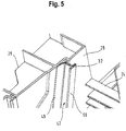
- a radial sealing lip 48 made of a flexible material is attached, which rests in the inserted state of the sealing insert 32 on the wall of the process air channel 28 ( FIG. 4 ). In FIG. 5 this can be seen in a section through the process air channel 28 and the sealing insert 32 with the radial sealing lip 48.
- an axial retaining rib 50 is formed circumferentially around the two parts of the flow opening 44.
- the filter support 34 forms, when it is inserted into the tumble dryer 10, a deflection channel 52 having an air inlet opening 54 and an air outlet opening 56 which directs the process air from the suction channel 26 into the process air channel 28. At the air outlet opening 56, the filter element 36 is attached.
- FIGS 3 and 4 are the components of the filter device separately, ie taken from the dryer 10 shown.
- the filter element 36 can be cleaned by the user, and the drip pan 38 can be emptied and cleaned.
- a ramp edge 58 is formed in the bottom group 29 on the side walls of the process air channel 28, which rises obliquely upward in the direction of insertion.
- the sealing insert 32 is received in the process air channel 28 so that it completely fills the cross section thereof.
- the edge of the sealing insert 32 is adapted to the cross-section of the process air channel 28, that between the wall, more precisely, the inner wall of the latter and the edge remains a gap which is sufficiently wide to receive the sealing lip 48, but narrow enough that the radial sealing lip 48 of the inner wall of the process air channel 28 is elastically deformed.
- the radial sealing lip 48 is then under tension against the inner wall of the process air channel 28.
- the gap between the sealing insert 32 and the inner wall of the process air channel 28 is sealed.
- the filter carrier 34 is inserted behind the sealing insert 32, so that the flow path between the suction channel 26 and the process air channel 28 is closed by the deflection channel 52 formed in the filter carrier 34.
- the filter support 34 is then fixed by means of locking elements 60 in the bottom group 29 and covered by the flap 18 of the inspection opening.
- the filter element 36 When inserted filter carrier 34, the filter element 36 is pressed against the back 42 of the sealing insert 32 and thus reliably fixed in its desired position.
- the filter element 36 protrudes radially with respect to the flow direction beyond the flow-through opening 44 of the sealing insert 32 addition. In conjunction with the sealing of the sealing insert 32 against the inner wall of the process air channel 28 is thus ensured that the process air must flow completely through the filter element and a bypass, the filter element 36 over, is prevented.
- the axial retaining rib 50 ensures that the filter element 36 receives additional support around the flow opening 44 by elastic deformation. This prevents a bypass flow possibly forming between the filter element 36 and the rear side 42 of the sealing insert 32, for example because the material of the filter element 36 lifts off the back 42 or the edge of the filter element slides into the flow opening 44.
- the Dichtungssmony 32 thus seals the ambient component, the process air duct 28 by a sealing system, the radial sealing lip 48 and at the same time provides the axial sealing seat for the foam filter element 36th ⁇ B> reference numerals ⁇ / b> clothes dryer 10 casing 12 washing drum 14 loading door 16 flap 18 Process air flow 20 heater 21 fan 22 heat exchangers 24 suction 26 Process air channel 28 underbody 29 filtering device 30 sealing insert 32 filter support 34 filter element 36 drip tray 38 front 40 back 42 flow-through 44 supporting web 46 sealing lip 48 holding rib 50 diversion channel 52 Air inlet opening 54 Air outlet opening 56 ramp edge 58 locking elements 60
Landscapes
- Engineering & Computer Science (AREA)
- Textile Engineering (AREA)
- Detail Structures Of Washing Machines And Dryers (AREA)
Abstract
Description
- Die Erfindung liegt auf dem Gebiet der Wäschebehandlungsmaschinen, wie insbesondere Wäschetrockner oder Kombinationsgeräte, sogenannte Waschtrockner, und betrifft eine Filtervorrichtung für eine Wäschebehandlungsmaschine. Die Erfindung betrifft ferner eine Wäschebehandlungsmaschine, die eine derartige Filtervorrichtung enthält.
- Derartige Filtervorrichtungen sind beispielsweise aus der
DE 10 2014 225 905 A1 oder derWO 2015/89085 A1 - Die
EP 2 455 537 A1 beschreibt einen Wäschetrockner mit einer in einem Gehäuse drehbar gelagerten Trommel, einer durch eine Tür verschließbare Beschickungsöffnung sowie einem Gebläse und einer Heizeinrichtung zur Erzeugung eines Prozeßluftstroms, der über einen Wärmetauscher strömt. Das Gehäuse weist in seiner Frontwand eine Revisionsklappe auf, durch die eine Filtervorrichtung zugänglich ist. Die Filtervorrichtung ist entlang des Prozeßluftstroms, also in Richtung des fließenden Prozeßluftstroms gesehen, dem Wärmetauscher vorgeordnet und weist eine Filtereinrichtung mit einem entnehmbaren Filtereinsatz (Filterelement) auf. - In der Wäschetrommel befindliche zu trocknende Wäsche wird während des Trocknungsvorganges von erwärmter Prozeßluft überströmt, die dabei neben der Feuchtigkeit aus der Wäsche auch Haare, Fusseln, Waschmittelrückstände und dergleichen aufnimmt (nachfolgend zusammenfassend als Flusen oder Verunreinigungen bezeichnet) und diese mitführt. Diese Flusen setzen sich an dem Filtereinsatz ab, der zur Aufrechterhaltung einer ausreichenden Trocknungsleistung und zum Schutz der nachfolgenden Komponenten in regelmäßigen Abständen von dem Benutzer aus der Filtervorrichtung entnommen, gesäubert oder bedarfsweise ausgetauscht und wieder eingesetzt werden muß. Dabei können durch Schrumpfung und Abnutzung des Filterelements oder anderer Bauteile Lücken entstehen, die von Prozeßluft bevorzugt durchströmt werden, mithin eine Bypaßströmung ausbilden. Die dabei am Filter vorbei mittransportierten Flusen belasten die Wärmetauscher, insbesondere für Hochleistungswärmetauscher mit engem Lamellenabstand wird eine solche Belastung als kritisch angesehen.
- Die Erfindung schafft eine Filtervorrichtung für eine Wäschebehandlungsmaschine die einfach in den Prozeßluftkreislauf der Wäschebehandlungsmaschine eingebracht werden kann und eine Bypaßströmung am Filter vorbei wirksam unterbindet sowie eine Wäschebehandlungsmaschine mit einer solchen Filtereinrichtung.
- Gemäß eines ersten Aspektes der Erfindung ist eine Filtervorrichtung für eine Wäschebehandlungsmaschine vorgesehen, die wenigstens einen in die Wäschebehandlungsmaschine einsetzbaren Dichtungseinsatz aufweist, wobei die Filtervorrichtung wenigstens einen in die Wäschebehandlungsmaschine einsetzbaren Filterträger mit einem Filterelement aufweist, wobei der Dichtungseinsatz unabhängig von dem Filterträger aus der Wäschebehandlungsmaschine entnehmbar ist, das Filterelement im eingesetzten Zustand in axialer Richtung dicht an einer Rückseite des Dichtungseinsatzes anliegt, und an dem Dichtungseinsatz eine radiale elastische Dichtlippe vorgesehen ist, welche den Dichtungseinsatz im eingesetzten Zustand gegen eine Prozeßluftführung der Wäschebehandlungsmaschine abdichtet.
- Diese Gestaltung der Filtereinrichtung bietet eine axiale Abdichtung des Filterelements, also in Einsetzrichtung des Filterelements: Durch das Einsetzen wird der Schaum zwischen seinem Trägerbauteil und dem axialen Dichtsitz an dem Dichtungseinsatzes komprimiert und damit sicher in seiner Soll-Position fixiert. Der Dichtungseinsatz dichtet sich zum Umgebungsbauteil, dem Prozeßluftkanal, der zum Wärmetauscher führt, durch ein Dichtsystem in Form der radialen Dichtlippe ab und bietet gleichzeitig den axialen Dichtsitz für den Schaum.
- Um die Reaktionskräfte der Dichtlippe auf den Dichtungseinsatz zu harmonisieren, sodaß es insbesondere an den Ecken nicht zu einer Erhöhung der Reaktionskräfte kommt, sind in einer vorteilhaften Weiterbildungen Maßnahmen vorgesehen, beispielsweise kann die radialen Dichtlippe auf einem kurzen Stück komplett unterbrochen sein, die Wandstärke der radialen Dichtlippe abschnittsweise, verringert sein und/oder die Lippenhöhe variiert sein.
- In einer vorteilhaften Ausführungsform ist bei der Filtervorrichtung an einer gegen die Strömungsrichtung weisenden Rückseite des Dichtungseinsatzes, umlaufend um eine Durchströmöffnung, eine axiale Halterippe ausgebildet. Dadurch wird verhindert, daß das Material des Filterelements sich von der Rückseite abhebt oder der Rand des Filterelements in die Durchströmöffnung rutscht und sich zwischen dem Filterelement und der Rückseite des Dichtungseinsatzes möglicherweise eine Bypaßströmung ausbilden kann.
- In einer weiteren vorteilhaften Ausführungsform ist bei derFiltervorrichtung an dem Dichtungseinsatz wenigstens ein Stützsteg vorgesehen ist, der die Durchströmöffnung in wenigstens zwei Teile teilt. Damit wird verhindert, daß das Filterelement unter der axialen Belastung durch den Prozeßluftstrom verformt, insbesondere ausgebeult wird.
- In einer weiteren vorteilhaften Ausführungsform ist bei der Filtervorrichtung eine Auffangwanne zum Einschieben in eine Prozeßluftführung der Wäschebehandlungsmaschine aufweist, an welcher der Dichtungseinsatz schwenkbar gelagert ist. Dies erleichtert das Einsetzen des Dichtungseinsatzes, der damit nicht separat handzuhaben ist, sondern beim Einschieben der Auffangwanne in seine Position gebracht werden kann. Insbesondere vorteilhaft kann an der Bodengruppe des Wäschebehandlungsgerätes im Bereich des Prozeßluftkanals eine schräg nach oben gerichtete Rampenkante ausgebildet sein, an der der Dichtungseinsatz beim Einschieben der Dichtungswanne entlanggleitet. Dabei wird der Dichtungseinsatz, der im herausgenommenen Zustand im wesentlichen flach auf der Auffangwanne aufliegt, relativ zu derselben verschwenkt und damit aufgerichtet bis er in seine Endlage kommt.
- In einer vorteilhaften Ausführungsform ist das Filterelement als Sandwich-Filtermatte ausgebildet.
- Gemäß eines weiteren Aspekts der Erfindung ist bei einer Wäschebehandlungsmaschine, mit einer Wäschetrommel und einer Prozeßluftstromführung zum Führen eines Prozeßluftstroms durch die Wäschetrommel und einen entlang des Prozeßluftstroms der Wäschetrommel nachgeordneten Wärmetauscher eine zwischen der Wäschetrommel und dem Wärmetauscher im Prozeßluftstrom angeordneten Filtervorrichtung der vorgenannten Art vorgesehen.
- In einer vorteilhaften Ausführungsform der Erfindung ist die Wäschebehandlungsmaschine, ein Wäschetrockner.
- Weitere Vorteile und Merkmale der Erfindung ergeben sich aus den Unteransprüchen und aus der nachfolgenden Beschreibung einer bevorzugten Ausführungsform unter Bezugnahme auf die beigefügten Zeichnungen.
- In den Zeichnungen zeigt:
- Fig. 1.
- eine perspektivische Darstellung einer Wäschebehandlungsmaschine gemäß einer bevorzugten Ausführungsform der Erfindung in Form eines Wäschetrockners,
- Fig. 2.
- der Wäschetrockner aus
Figur 1 in einer Schnittdarstellung; - Fig. 3.
- die erfindungsgemäße Filtervorrichtung aus dem Wäschetrockner nach
Figur 2 in einer perspektivischen Detaildarstellung; - Fig. 4.
- die Filtervorrichtung aus dem Wäschetrockner nach
Figur 2 in einer geschnittenen Detaildarstellung; - Fig. 5.
- einen vergrößerten Schnitt durch einen Teil des Prozeßluftkanals und des Dichtungseinsatzes der Filtervorrichtung aus
Figur 3 . -
Figur 1 zeigt in perspektivischer Darstellung eine Wäschebehandlungsmaschine gemäß einer Ausführungsform der Erfindung in Form eines Wäschetrockners 10. Der Wäschetrockner 10 weist ein Gehäuse 12 auf, in dem eine Wäschetrommel 14 gelagert ist. Eine Beschickungstür 16 verschließt eine Beschickungsöffnung, durch welche zu trocknende Wäsche (nicht dargestellt) in die Wäschetrommel 14 eingelegt werden kann. - In der Frontseite des Gehäuses 12 ist eine Revisionsöffnung mit einer Klappe 18 vorgesehen (
Figur 1 ), die in geöffnetem Zustand den Zugriff auf eine Filtereinrichtung 30 freigibt, welche weiter unten genauer beschrieben ist. - In dem Wäschetrockner 10 ist ein Prozeßluftstrom 20 in einer Prozeßluftstromführung geführt, deren Elemente in
Figur 2 in einem schematischen Schnitt durch den Wäschetrockner 10 dargestellt sind. Hierbei wird die in einer Heizeinrichtung 21 erwärmte Prozeßluft in an sich bekannter Weise in einem Kreislauf mit Hilfe eines Gebläses 22 durch die Wäschetrommel 14 und anschließend zu einem Wärmetauscher 24 geführt. - Strömungsseitig vor dem Wärmetauscher 24 ist eine Filtereinrichtung 30 vorgesehen. Wie in
Figur 2 dargestellt, wird die feuchte Prozeßluft durch einen Absaugkanal 26 aus der Wäschetrommel 14 über die Filtereinrichtung 30 in einen Prozeßluftkanal 28 geführt, in welchem der Wärmetauscher 24 untergebracht ist. Vorteilhaft ist der Prozeßluftkanal 28 in einer Bodengruppe 29 ausgeformt, die als Kunststoffteil ausgebildet ist und die auch weitere Baugruppen, beispielsweise das Gebläse 22 und einen Kompressor (nicht dargestellt) aufnehmen kann und das Fundament des Wäschetrockners 10 bildet. - Die Filtereinrichtung 30, die in den
Figuren 3 und4 detaillierter dargestellt ist, weist in der gezeigten Ausführungsform einen Dichtungseinsatz 32 und einen Filterträger 34 mit einem Filterelement 36 aus einem offenporigen Schaumstoff auf. - Der Dichtungseinsatz 32 ist schwenkbar an einer Auffangwanne 38 gelagert, welche zum Betrieb des Wäschetrockners in den Prozeßluftkanal 28 eingeschoben ist und unter den Wärmetauscher 24 ragt um die mittels einer Spüleinrichtung (nicht dargestellt) vom Wärmetauscher 24 abgespülte Flusen zu sammeln
- Der Dichtungseinsatz 32 ist als im wesentlichen ebener Rahmen ausgebildet. Als Rahmen umschließt der Dichtungseinsatz 32 naturgemäß eine Durchströmöffnung 44. Die Hauptebene des Dichtungseinsatzes 32 definiert eine zum Wärmetauscher weisende Vorderseite 40 und eine vom Wärmetauscher 24 weg weisenden Rückseite 42. Bezogen auf den Dichtungseinsatz seien die Richtungen parallel zum Normalenvektor der Hauptebene als axiale Richtungen bezeichnet; Richtungen senkrecht dazu als radiale Richtungen. Im eingesetzten Zustand wird der Dichtungseinsatz 32 durch die Durchströmöffnung 44 in im wesentlichen axialer Richtung, der zum Wärmetauscher 24 hin, also von der Rückseite 42 zur Vorderseite 40 durchströmt. Zur Stabilisierung des Dichtungseinsatzes 32 ist ein Stützsteg 46 vorgesehen, der die Durchströmöffnung 44 in zwei Teile 44a und 44b teilt.
- Am Rand des Dichtungseinsatzes 32 ist eine radiale Dichtlippe 48 aus einem flexiblen Material angebracht, die im eingesetzten Zustand des Dichtungseinsatzes 32 an der Wand des Prozeßluftkanals 28 anliegt (
Figur 4 ). InFigur 5 ist dies in einem Schnitt durch den Prozeßluftkanal 28 und den Dichtungseinsatz 32 mit der radialen Dichtlippe 48 zu sehen. Auf der Rückseite 42 ist umlaufend um die beiden Teile der Durchströmöffnung 44 eine axiale Halterippe 50 ausgebildet. - Der Filterträger 34 bildet, wenn er in den Wäschetrockner 10 eingesetzt ist, einen Umlenkkanal 52 mit einer Lufteintrittsöffnung 54 und einer Luftaustrittsöffnung 56, der die Prozeßluft aus dem Absaugkanal 26 in den Prozeßluftkanal 28 leitet. An der Luftaustrittsöffnung 56 ist das Filterelement 36 angebracht.
- In den
Figuren 3 und4 sind die Bestandteile der Filtereinrichtung separat, d.h. aus dem Wäschetrockner 10 entnommen, dargestellt. In diesem Zustand kann das Filterelement 36 durch den Benutzer gereinigt, sowie die Auffangwanne 38 entleert und gereinigt werden. Zum Betrieb des Wäschetrockners 10 ist die Auffangwanne 38 mit dem Dichtungseinsatz 32 in im wesentlichen axialer Richtung, bzw. in Richtung der Prozeßluftströmung in den Prozeßluftkanal 28 einzuschieben und danach der Filterträger 34 einzusetzen. - In vorteilhafter Weise ist in der Bodengruppe 29 an den Seitenwänden des Prozeßluftkanals 28 jeweils eine Rampenkante 58 ausgebildet, die in Einschubrichtung schräg nach oben ansteigt. Beim Einschieben der Auffangwanne 38 in den Prozeßluftkanal 28 kommen die Seitenkanten des Dichtungseinsatzes 32, der zunächst flach auf der Auffangwanne 38 aufliegt, mit den Rampenkanten 58 in Kontakt und gleiten auf diesem nach oben, sodaß der Dichtungseinsatz 32 in seiner Lagerung an der Auffangwanne 38 verschwenkt und damit aufgerichtet wird. Das heißt also, daß beim Einschieben der Auffangwanne 38 in die Bodengruppe 29 automatisch der Dichtungseinsatz 32 aufgerichtet und so positioniert wird, daß danach der Filterträger34 eingesetzt werden kann.
- Sobald die Auffangwanne 38 vollständig eingeschoben ist, ist der Dichtungseinsatz 32 im Prozeßluftkanal 28 aufgenommen, sodaß er den Querschnitt desselben vollständig ausfüllt. Der Rand des Dichtungseinsatzes 32 ist so an den Querschnitt des Prozeßluftkanals 28 angepaßt, daß zwischen der Wand, genauer der Innenwand des letzteren und dem Rand ein Spalt bleibt, der ausreichend weit ist, die Dichtlippe 48 aufzunehmen, aber eng genug, daß die radiale Dichtlippe 48 von der der Innenwand des Prozeßluftkanals 28 elastisch verformt ist. Die radiale Dichtlippe 48 liegt dann unter Spannung an der Innenwand des Prozeßluftkanals 28 an. Damit ist der Spalt zwischen dem Dichtungseinsatz 32 und der Innenwand des Prozeßluftkanals 28 abgedichtet.
- Der Filterträger 34 wird hinter dem Dichtungseinsatz 32 eingesetzt, sodaß durch den im Filterträger 34 ausgebildeten Umlenkkanal 52 der Strömungsweg zwischen dem Absaugkanal 26 und dem Prozeßluftkanal 28 geschlossen ist. Der Filterträger 34 wird dann mittels Verriegelungselementen 60 in der Bodengruppe 29 fixiert und von der Klappe 18 der Revisionsöffnung verdeckt.
- Bei eingesetztem Filterträger 34 ist das Filterelement 36 an die Rückseite 42 des Dichtungseinsatzes 32 gepreßt und damit zuverlässig in seiner Soll-Position fixiert. Das Filterelement 36 ragt dabei radial bezüglich der Strömungsrichtung über die Durchströmöffnung 44 des Dichtungseinsatzes 32 hinaus. In Verbindung mit der Abdichtung des Dichtungseinsatzes 32 gegen die Innenwand des Prozeßluftkanals 28 ist damit sichergestellt, daß die Prozeßluft vollständig durch das Filterelement strömen muß und ein Bypaß, am Filterelement 36 vorbei, verhindert ist.
- Zusätzlich sorgt die axiale Halterippe 50 dafür, daß das Filterelement 36 durch elastische Verformung um die Durchströmöffnung 44 herum zusätzlichen Halt erhält. Damit wird verhindert, daß sich zwischen dem Filterelement 36 und der Rückseite 42 des Dichtungseinsatzes 32 möglicherweise eine Bypaßströmung bildet, beispielsweise, weil das Material des Filterelements 36 sich von der Rückseite 42 abhebt oder der Rand des Filterelements in die Durchströmöffnung 44 rutscht.
- Der Dichtungseinsatze 32 dichtet somit zum Umgebungsbauteil, dem Prozeßluftkanal 28 durch ein Dichtsystem, die radiale Dichtlippe 48 ab und bietet gleichzeitig den axialen Dichtsitz für das Schaum-Filterelement 36.
Bezugszeichen Wäschetrockner 10 Gehäuse 12 Wäschetrommel 14 Beschickungstür 16 Klappe 18 Prozeßluftstrom 20 Heizeinrichtung 21 Gebläse 22 Wärmetauscher 24 Absaugkanal 26 Prozeßluftkanal 28 Bodengruppe 29 Filtereinrichtung 30 Dichtungseinsatz 32 Filterträger 34 Filterelement 36 Auffangwanne 38 Vorderseite 40 Rückseite 42 Durchströmöffnung 44 Stützsteg 46 Dichtlippe 48 Halterippe 50 Umlenkkanal 52 Lufteintrittsöffnung 54 Luftaustrittsöffnung 56 Rampenkante 58 Verriegelungselemente 60
Claims (6)
- Filtervorrichtung (30) für eine Wäschebehandlungsmaschine (10),- die Filtervorrichtung (30) wenigstens einen in die Wäschebehandlungsmaschine (10) einsetzbaren Dichtungseinsatz (32) aufweist,- die Filtervorrichtung (30) wenigstens einen in die Wäschebehandlungsmaschine (10) einsetzbaren Filterträger (14) mit einem Filterelement aufweist,- der Dichtungseinsatz (32) unabhängig von dem Filterträger (14) aus der Wäschebehandlungsmaschine (10) entnehmbar ist,- das Filterelement (36) im eingesetzten Zustand in axialer Richtung dicht an einer Rückseite des Dichtungseinsatz (32) anliegt, und- an dem Dichtungseinsatz (32) eine radiale elastische Dichtlippe (48) vorgesehen ist, welche den Dichtungseinsatz (32) im eingesetzten Zustand gegen eine Prozeßluftführung der Wäschebehandlungsmaschine (10) abdichtet.
- Filtervorrichtung (30) nach Anspruch 1, bei der an einer gegen die Strömungsrichtung weisenden Rückseite 42 des Dichtungseinsatzes 32, umlaufend um eine Durchströmöffnung 44, eine axiale Halterippe 50 ausgebildet ist.
- Filtervorrichtung (30) nach einem der Ansprüche 1 oder 2, bei der an dem Dichtungseinsatz (32) ein Stützsteg (46) vorgesehen ist, der eine Durchströmöffnung (44) in zwei Teile (44a, 44b) teilt.
- Filtervorrichtung (30) nach einem der vorhergehenden Ansprüche, die eine Auffangwanne (38) zum Einschieben in eine Prozeßluftführung der Wäschebehandlungsmaschine (10) aufweist, an welcher der Dichtungseinsatz (32) schwenkbar gelagert ist.
- Wäschebehandlungsmaschine (10), mit einer Wäschetrommel (14) und einer Prozeßluftstromführung (20) zum Führen eines Prozeßluftstroms durch die Wäschetrommel (14) und einen entlang des Prozeßluftstroms der Wäschetrommel (14) nachgeordneten Wärmetauscher sowie einer zwischen der Wäschetrommel (14) und dem Wärmetauscher (24) im Prozeßluftstrom angeordneten Filtervorrichtung (30) nach einem der vorhergehenden Ansprüche.
- Wäschebehandlungsmaschine (10) nach dem unmittelbar vorhergehenden Anspruch, welche ein Wäschetrockner (10) ist.
Priority Applications (1)
| Application Number | Priority Date | Filing Date | Title |
|---|---|---|---|
| PL19174076T PL3575482T3 (pl) | 2018-05-30 | 2019-05-13 | Maszyna do obróbki prania z przyrządem filtracyjnym |
Applications Claiming Priority (1)
| Application Number | Priority Date | Filing Date | Title |
|---|---|---|---|
| DE102018208559.5A DE102018208559A1 (de) | 2018-05-30 | 2018-05-30 | Filtervorrichtung für eine Wäschebehandlungsmaschine und Wäschebehandlungsmaschine mit einer solchen |
Publications (2)
| Publication Number | Publication Date |
|---|---|
| EP3575482A1 true EP3575482A1 (de) | 2019-12-04 |
| EP3575482B1 EP3575482B1 (de) | 2022-02-09 |
Family
ID=66529862
Family Applications (1)
| Application Number | Title | Priority Date | Filing Date |
|---|---|---|---|
| EP19174076.0A Active EP3575482B1 (de) | 2018-05-30 | 2019-05-13 | Wäschebehandlungsmaschine mit einer filtervorrichtung |
Country Status (4)
| Country | Link |
|---|---|
| EP (1) | EP3575482B1 (de) |
| CN (1) | CN110552180B (de) |
| DE (1) | DE102018208559A1 (de) |
| PL (1) | PL3575482T3 (de) |
Citations (8)
| Publication number | Priority date | Publication date | Assignee | Title |
|---|---|---|---|---|
| EP2392723A2 (de) * | 2011-09-12 | 2011-12-07 | V-Zug AG | Wäschetrockner mit einem Filter |
| EP2455537A1 (de) | 2010-11-19 | 2012-05-23 | Miele & Cie. KG | Wäschetrockner mit Filtereinsatz |
| WO2013178517A1 (de) * | 2012-05-30 | 2013-12-05 | BSH Bosch und Siemens Hausgeräte GmbH | Aufnahmevorrichtung für einen entnehmbaren filter eines haushaltsgeräts |
| EP2801653A2 (de) * | 2013-05-06 | 2014-11-12 | Miele & Cie. KG | Wäschetrockner mit einer Revisionsklappe |
| WO2015089085A1 (en) | 2013-12-09 | 2015-06-18 | Seymour Segnit | Wall-mounted charging device and modular outlet extender |
| DE102014225905A1 (de) | 2014-12-15 | 2016-06-16 | BSH Hausgeräte GmbH | Filtereinrichtung und Wäschetrockner, der die Filtereinrichtung enthält |
| WO2016095970A1 (en) * | 2014-12-16 | 2016-06-23 | Electrolux Appliances Aktiebolag | Laundry drying apparatus with a filter system |
| EP3135804A1 (de) * | 2015-08-27 | 2017-03-01 | BSH Hausgeräte GmbH | Wäschetrocknungsgerät mit einem türflusensieb-sitz und verfahren zu seiner herstellung |
Family Cites Families (9)
| Publication number | Priority date | Publication date | Assignee | Title |
|---|---|---|---|---|
| IT248008Y1 (it) * | 1999-01-19 | 2002-12-09 | Electrolux Zanussi Elettrodome | Essiccatore di biancheria a tamburo del tipo a esplusione |
| JP3898675B2 (ja) * | 2003-08-22 | 2007-03-28 | 松下電器産業株式会社 | ドラム式洗濯乾燥機 |
| ATE378454T1 (de) * | 2004-03-16 | 2007-11-15 | Arcelik As | Waschtrockner |
| DE102005035652A1 (de) * | 2005-07-29 | 2007-02-01 | BSH Bosch und Siemens Hausgeräte GmbH | Wärmetauschvorrichtung für einen Wäschetrockner |
| US9593441B2 (en) * | 2014-02-28 | 2017-03-14 | ADR Products, LLC | Lint catching system and exhaust assembly |
| DE102014211304A1 (de) * | 2014-06-13 | 2015-12-17 | BSH Hausgeräte GmbH | Filtervorrichtung für eine Wäschebehandlungsmaschine und Wäschebehandlungsmaschine mit einer solchen |
| WO2016192979A1 (en) * | 2015-06-02 | 2016-12-08 | Arcelik Anonim Sirketi | A laundry washing and drying machine comprising a filter |
| DE102015110215A1 (de) * | 2015-06-25 | 2016-12-29 | Miele & Cie. Kg | Wäschetrockner mit einer in einem Gehäuse drehbar gelagerten Trommel |
| SI3112514T1 (en) * | 2015-06-30 | 2018-03-30 | V-Zug Ag | Dryer with filter cartridge for flakes |
-
2018
- 2018-05-30 DE DE102018208559.5A patent/DE102018208559A1/de not_active Withdrawn
-
2019
- 2019-05-13 PL PL19174076T patent/PL3575482T3/pl unknown
- 2019-05-13 EP EP19174076.0A patent/EP3575482B1/de active Active
- 2019-05-29 CN CN201910455529.5A patent/CN110552180B/zh active Active
Patent Citations (8)
| Publication number | Priority date | Publication date | Assignee | Title |
|---|---|---|---|---|
| EP2455537A1 (de) | 2010-11-19 | 2012-05-23 | Miele & Cie. KG | Wäschetrockner mit Filtereinsatz |
| EP2392723A2 (de) * | 2011-09-12 | 2011-12-07 | V-Zug AG | Wäschetrockner mit einem Filter |
| WO2013178517A1 (de) * | 2012-05-30 | 2013-12-05 | BSH Bosch und Siemens Hausgeräte GmbH | Aufnahmevorrichtung für einen entnehmbaren filter eines haushaltsgeräts |
| EP2801653A2 (de) * | 2013-05-06 | 2014-11-12 | Miele & Cie. KG | Wäschetrockner mit einer Revisionsklappe |
| WO2015089085A1 (en) | 2013-12-09 | 2015-06-18 | Seymour Segnit | Wall-mounted charging device and modular outlet extender |
| DE102014225905A1 (de) | 2014-12-15 | 2016-06-16 | BSH Hausgeräte GmbH | Filtereinrichtung und Wäschetrockner, der die Filtereinrichtung enthält |
| WO2016095970A1 (en) * | 2014-12-16 | 2016-06-23 | Electrolux Appliances Aktiebolag | Laundry drying apparatus with a filter system |
| EP3135804A1 (de) * | 2015-08-27 | 2017-03-01 | BSH Hausgeräte GmbH | Wäschetrocknungsgerät mit einem türflusensieb-sitz und verfahren zu seiner herstellung |
Also Published As
| Publication number | Publication date |
|---|---|
| PL3575482T3 (pl) | 2022-05-23 |
| CN110552180A (zh) | 2019-12-10 |
| DE102018208559A1 (de) | 2019-12-05 |
| CN110552180B (zh) | 2023-03-24 |
| EP3575482B1 (de) | 2022-02-09 |
Similar Documents
| Publication | Publication Date | Title |
|---|---|---|
| DE112011101522B4 (de) | Wäschevorrichtung | |
| DE102008020671B4 (de) | Bekleidungsbehandlungsmaschine | |
| EP1636411B1 (de) | Wäschetrockner | |
| EP2107155B1 (de) | Wäschebehandlungsmaschine insbesondere Wäschetrockner | |
| EP2855759B1 (de) | Aufnahmevorrichtung für einen entnehmbaren filter eines haushaltsgeräts | |
| DE102007008827A1 (de) | Gewerbliche Geschirrspülmaschine | |
| DE102008055086A1 (de) | Wäschetrocknungsgerät und Verfahren zum Reinigen eines Siebs | |
| DE1519934A1 (de) | Duese fuer Fluessigkeitsextraktionsvorrichtung | |
| DE102008014305A1 (de) | Ablufttrockner mit Umluftanteil sowie Verfahren zu seinem Betrieb | |
| DE102017103306B4 (de) | Gerät zur Behandlung von Wäsche und Steuerverfahren dafür | |
| EP1699969B1 (de) | Trocknungskorb und befestigungseinrichtung für einen trocknungskorb an einem wäschetrockner | |
| DE102006023952B4 (de) | Wäschetrockner | |
| EP3575482B1 (de) | Wäschebehandlungsmaschine mit einer filtervorrichtung | |
| EP3213666A1 (de) | Geschirrspülmaschine | |
| DE102018128709A1 (de) | Trocknungseinrichtung für ein wasserführendes Reinigungsgerät | |
| DE102009001323A1 (de) | Vorrichtung und Verfahren zum Schleudern von Wäsche | |
| EP3112514B1 (de) | Wäschetrockner mit flusenfilterkassette | |
| EP3272934A1 (de) | Filtereinsatz und gerät zum behandeln von wäsche | |
| DE2324518A1 (de) | Vorrichtung zum trocknen von kleidungsstuecken oder dergl | |
| EP3536847B1 (de) | Wärmepumpengerät | |
| LU103433B1 (de) | Trocknungseinrichtung, insbesondere Umlufttrocknungseinrichtung | |
| BE1032372B1 (de) | Trocknungseinrichtung, insbesondere Umlufttrocknungseinrichtung | |
| DE102024131125A1 (de) | Trocknungseinrichtung, insbesondere Umlufttrocknungseinrichtung | |
| EP3135803A1 (de) | Prozessluftanordnung für ein trocknungsgerät sowie trocknungsgerät | |
| DE102023200168A1 (de) | Haushaltsgerät zur Pflege von Wäschestücken mit einer in eine Belüftungsstellung bewegbaren Manschette und Verfahren zum Betreiben eines Haushaltsgeräts |
Legal Events
| Date | Code | Title | Description |
|---|---|---|---|
| PUAI | Public reference made under article 153(3) epc to a published international application that has entered the european phase |
Free format text: ORIGINAL CODE: 0009012 |
|
| STAA | Information on the status of an ep patent application or granted ep patent |
Free format text: STATUS: THE APPLICATION HAS BEEN PUBLISHED |
|
| AK | Designated contracting states |
Kind code of ref document: A1 Designated state(s): AL AT BE BG CH CY CZ DE DK EE ES FI FR GB GR HR HU IE IS IT LI LT LU LV MC MK MT NL NO PL PT RO RS SE SI SK SM TR |
|
| AX | Request for extension of the european patent |
Extension state: BA ME |
|
| STAA | Information on the status of an ep patent application or granted ep patent |
Free format text: STATUS: REQUEST FOR EXAMINATION WAS MADE |
|
| 17P | Request for examination filed |
Effective date: 20200604 |
|
| RBV | Designated contracting states (corrected) |
Designated state(s): AL AT BE BG CH CY CZ DE DK EE ES FI FR GB GR HR HU IE IS IT LI LT LU LV MC MK MT NL NO PL PT RO RS SE SI SK SM TR |
|
| STAA | Information on the status of an ep patent application or granted ep patent |
Free format text: STATUS: EXAMINATION IS IN PROGRESS |
|
| 17Q | First examination report despatched |
Effective date: 20210324 |
|
| GRAP | Despatch of communication of intention to grant a patent |
Free format text: ORIGINAL CODE: EPIDOSNIGR1 |
|
| STAA | Information on the status of an ep patent application or granted ep patent |
Free format text: STATUS: GRANT OF PATENT IS INTENDED |
|
| RIC1 | Information provided on ipc code assigned before grant |
Ipc: D06F 25/00 20060101ALN20210907BHEP Ipc: D06F 58/22 20060101AFI20210907BHEP |
|
| RIC1 | Information provided on ipc code assigned before grant |
Ipc: D06F 25/00 20060101ALN20210910BHEP Ipc: D06F 58/22 20060101AFI20210910BHEP |
|
| INTG | Intention to grant announced |
Effective date: 20211004 |
|
| RIN1 | Information on inventor provided before grant (corrected) |
Inventor name: THUEMMLER, ANDREAS Inventor name: SEYRING, MIKE Inventor name: SCHUBERT, MARTIN Inventor name: HENNIG, HOLGER Inventor name: BOEMMELS, RALF |
|
| GRAS | Grant fee paid |
Free format text: ORIGINAL CODE: EPIDOSNIGR3 |
|
| GRAA | (expected) grant |
Free format text: ORIGINAL CODE: 0009210 |
|
| STAA | Information on the status of an ep patent application or granted ep patent |
Free format text: STATUS: THE PATENT HAS BEEN GRANTED |
|
| AK | Designated contracting states |
Kind code of ref document: B1 Designated state(s): AL AT BE BG CH CY CZ DE DK EE ES FI FR GB GR HR HU IE IS IT LI LT LU LV MC MK MT NL NO PL PT RO RS SE SI SK SM TR |
|
| REG | Reference to a national code |
Ref country code: GB Ref legal event code: FG4D Free format text: NOT ENGLISH |
|
| REG | Reference to a national code |
Ref country code: CH Ref legal event code: EP Ref country code: AT Ref legal event code: REF Ref document number: 1467578 Country of ref document: AT Kind code of ref document: T Effective date: 20220215 |
|
| REG | Reference to a national code |
Ref country code: DE Ref legal event code: R096 Ref document number: 502019003382 Country of ref document: DE |
|
| REG | Reference to a national code |
Ref country code: IE Ref legal event code: FG4D Free format text: LANGUAGE OF EP DOCUMENT: GERMAN |
|
| REG | Reference to a national code |
Ref country code: LT Ref legal event code: MG9D |
|
| REG | Reference to a national code |
Ref country code: NL Ref legal event code: MP Effective date: 20220209 |
|
| PG25 | Lapsed in a contracting state [announced via postgrant information from national office to epo] |
Ref country code: SE Free format text: LAPSE BECAUSE OF FAILURE TO SUBMIT A TRANSLATION OF THE DESCRIPTION OR TO PAY THE FEE WITHIN THE PRESCRIBED TIME-LIMIT Effective date: 20220209 Ref country code: RS Free format text: LAPSE BECAUSE OF FAILURE TO SUBMIT A TRANSLATION OF THE DESCRIPTION OR TO PAY THE FEE WITHIN THE PRESCRIBED TIME-LIMIT Effective date: 20220209 Ref country code: PT Free format text: LAPSE BECAUSE OF FAILURE TO SUBMIT A TRANSLATION OF THE DESCRIPTION OR TO PAY THE FEE WITHIN THE PRESCRIBED TIME-LIMIT Effective date: 20220609 Ref country code: NO Free format text: LAPSE BECAUSE OF FAILURE TO SUBMIT A TRANSLATION OF THE DESCRIPTION OR TO PAY THE FEE WITHIN THE PRESCRIBED TIME-LIMIT Effective date: 20220509 Ref country code: NL Free format text: LAPSE BECAUSE OF FAILURE TO SUBMIT A TRANSLATION OF THE DESCRIPTION OR TO PAY THE FEE WITHIN THE PRESCRIBED TIME-LIMIT Effective date: 20220209 Ref country code: LT Free format text: LAPSE BECAUSE OF FAILURE TO SUBMIT A TRANSLATION OF THE DESCRIPTION OR TO PAY THE FEE WITHIN THE PRESCRIBED TIME-LIMIT Effective date: 20220209 Ref country code: HR Free format text: LAPSE BECAUSE OF FAILURE TO SUBMIT A TRANSLATION OF THE DESCRIPTION OR TO PAY THE FEE WITHIN THE PRESCRIBED TIME-LIMIT Effective date: 20220209 Ref country code: ES Free format text: LAPSE BECAUSE OF FAILURE TO SUBMIT A TRANSLATION OF THE DESCRIPTION OR TO PAY THE FEE WITHIN THE PRESCRIBED TIME-LIMIT Effective date: 20220209 Ref country code: BG Free format text: LAPSE BECAUSE OF FAILURE TO SUBMIT A TRANSLATION OF THE DESCRIPTION OR TO PAY THE FEE WITHIN THE PRESCRIBED TIME-LIMIT Effective date: 20220509 |
|
| PG25 | Lapsed in a contracting state [announced via postgrant information from national office to epo] |
Ref country code: LV Free format text: LAPSE BECAUSE OF FAILURE TO SUBMIT A TRANSLATION OF THE DESCRIPTION OR TO PAY THE FEE WITHIN THE PRESCRIBED TIME-LIMIT Effective date: 20220209 Ref country code: GR Free format text: LAPSE BECAUSE OF FAILURE TO SUBMIT A TRANSLATION OF THE DESCRIPTION OR TO PAY THE FEE WITHIN THE PRESCRIBED TIME-LIMIT Effective date: 20220510 Ref country code: FI Free format text: LAPSE BECAUSE OF FAILURE TO SUBMIT A TRANSLATION OF THE DESCRIPTION OR TO PAY THE FEE WITHIN THE PRESCRIBED TIME-LIMIT Effective date: 20220209 |
|
| PG25 | Lapsed in a contracting state [announced via postgrant information from national office to epo] |
Ref country code: IS Free format text: LAPSE BECAUSE OF FAILURE TO SUBMIT A TRANSLATION OF THE DESCRIPTION OR TO PAY THE FEE WITHIN THE PRESCRIBED TIME-LIMIT Effective date: 20220609 |
|
| PG25 | Lapsed in a contracting state [announced via postgrant information from national office to epo] |
Ref country code: SM Free format text: LAPSE BECAUSE OF FAILURE TO SUBMIT A TRANSLATION OF THE DESCRIPTION OR TO PAY THE FEE WITHIN THE PRESCRIBED TIME-LIMIT Effective date: 20220209 Ref country code: SK Free format text: LAPSE BECAUSE OF FAILURE TO SUBMIT A TRANSLATION OF THE DESCRIPTION OR TO PAY THE FEE WITHIN THE PRESCRIBED TIME-LIMIT Effective date: 20220209 Ref country code: RO Free format text: LAPSE BECAUSE OF FAILURE TO SUBMIT A TRANSLATION OF THE DESCRIPTION OR TO PAY THE FEE WITHIN THE PRESCRIBED TIME-LIMIT Effective date: 20220209 Ref country code: EE Free format text: LAPSE BECAUSE OF FAILURE TO SUBMIT A TRANSLATION OF THE DESCRIPTION OR TO PAY THE FEE WITHIN THE PRESCRIBED TIME-LIMIT Effective date: 20220209 Ref country code: DK Free format text: LAPSE BECAUSE OF FAILURE TO SUBMIT A TRANSLATION OF THE DESCRIPTION OR TO PAY THE FEE WITHIN THE PRESCRIBED TIME-LIMIT Effective date: 20220209 Ref country code: CZ Free format text: LAPSE BECAUSE OF FAILURE TO SUBMIT A TRANSLATION OF THE DESCRIPTION OR TO PAY THE FEE WITHIN THE PRESCRIBED TIME-LIMIT Effective date: 20220209 |
|
| REG | Reference to a national code |
Ref country code: DE Ref legal event code: R097 Ref document number: 502019003382 Country of ref document: DE |
|
| PG25 | Lapsed in a contracting state [announced via postgrant information from national office to epo] |
Ref country code: AL Free format text: LAPSE BECAUSE OF FAILURE TO SUBMIT A TRANSLATION OF THE DESCRIPTION OR TO PAY THE FEE WITHIN THE PRESCRIBED TIME-LIMIT Effective date: 20220209 |
|
| PLBE | No opposition filed within time limit |
Free format text: ORIGINAL CODE: 0009261 |
|
| STAA | Information on the status of an ep patent application or granted ep patent |
Free format text: STATUS: NO OPPOSITION FILED WITHIN TIME LIMIT |
|
| REG | Reference to a national code |
Ref country code: CH Ref legal event code: PL |
|
| 26N | No opposition filed |
Effective date: 20221110 |
|
| REG | Reference to a national code |
Ref country code: BE Ref legal event code: MM Effective date: 20220531 |
|
| PG25 | Lapsed in a contracting state [announced via postgrant information from national office to epo] |
Ref country code: MC Free format text: LAPSE BECAUSE OF FAILURE TO SUBMIT A TRANSLATION OF THE DESCRIPTION OR TO PAY THE FEE WITHIN THE PRESCRIBED TIME-LIMIT Effective date: 20220209 Ref country code: LU Free format text: LAPSE BECAUSE OF NON-PAYMENT OF DUE FEES Effective date: 20220513 Ref country code: LI Free format text: LAPSE BECAUSE OF NON-PAYMENT OF DUE FEES Effective date: 20220531 Ref country code: CH Free format text: LAPSE BECAUSE OF NON-PAYMENT OF DUE FEES Effective date: 20220531 |
|
| PG25 | Lapsed in a contracting state [announced via postgrant information from national office to epo] |
Ref country code: SI Free format text: LAPSE BECAUSE OF FAILURE TO SUBMIT A TRANSLATION OF THE DESCRIPTION OR TO PAY THE FEE WITHIN THE PRESCRIBED TIME-LIMIT Effective date: 20220209 |
|
| PG25 | Lapsed in a contracting state [announced via postgrant information from national office to epo] |
Ref country code: IE Free format text: LAPSE BECAUSE OF NON-PAYMENT OF DUE FEES Effective date: 20220513 Ref country code: FR Free format text: LAPSE BECAUSE OF NON-PAYMENT OF DUE FEES Effective date: 20220531 |
|
| PG25 | Lapsed in a contracting state [announced via postgrant information from national office to epo] |
Ref country code: BE Free format text: LAPSE BECAUSE OF NON-PAYMENT OF DUE FEES Effective date: 20220531 |
|
| PG25 | Lapsed in a contracting state [announced via postgrant information from national office to epo] |
Ref country code: IT Free format text: LAPSE BECAUSE OF FAILURE TO SUBMIT A TRANSLATION OF THE DESCRIPTION OR TO PAY THE FEE WITHIN THE PRESCRIBED TIME-LIMIT Effective date: 20220209 |
|
| GBPC | Gb: european patent ceased through non-payment of renewal fee |
Effective date: 20230513 |
|
| PG25 | Lapsed in a contracting state [announced via postgrant information from national office to epo] |
Ref country code: HU Free format text: LAPSE BECAUSE OF FAILURE TO SUBMIT A TRANSLATION OF THE DESCRIPTION OR TO PAY THE FEE WITHIN THE PRESCRIBED TIME-LIMIT; INVALID AB INITIO Effective date: 20190513 |
|
| PG25 | Lapsed in a contracting state [announced via postgrant information from national office to epo] |
Ref country code: MK Free format text: LAPSE BECAUSE OF FAILURE TO SUBMIT A TRANSLATION OF THE DESCRIPTION OR TO PAY THE FEE WITHIN THE PRESCRIBED TIME-LIMIT Effective date: 20220209 Ref country code: CY Free format text: LAPSE BECAUSE OF FAILURE TO SUBMIT A TRANSLATION OF THE DESCRIPTION OR TO PAY THE FEE WITHIN THE PRESCRIBED TIME-LIMIT Effective date: 20220209 Ref country code: GB Free format text: LAPSE BECAUSE OF NON-PAYMENT OF DUE FEES Effective date: 20230513 |
|
| PG25 | Lapsed in a contracting state [announced via postgrant information from national office to epo] |
Ref country code: MT Free format text: LAPSE BECAUSE OF FAILURE TO SUBMIT A TRANSLATION OF THE DESCRIPTION OR TO PAY THE FEE WITHIN THE PRESCRIBED TIME-LIMIT Effective date: 20220209 |
|
| PGFP | Annual fee paid to national office [announced via postgrant information from national office to epo] |
Ref country code: DE Payment date: 20250531 Year of fee payment: 7 Ref country code: PL Payment date: 20250430 Year of fee payment: 7 |
|
| REG | Reference to a national code |
Ref country code: AT Ref legal event code: MM01 Ref document number: 1467578 Country of ref document: AT Kind code of ref document: T Effective date: 20240513 |
|
| PG25 | Lapsed in a contracting state [announced via postgrant information from national office to epo] |
Ref country code: AT Free format text: LAPSE BECAUSE OF NON-PAYMENT OF DUE FEES Effective date: 20240513 |
|
| PGFP | Annual fee paid to national office [announced via postgrant information from national office to epo] |
Ref country code: TR Payment date: 20250506 Year of fee payment: 7 |
|
| PGFP | Annual fee paid to national office [announced via postgrant information from national office to epo] |
Ref country code: AT Payment date: 20260410 Year of fee payment: 5 |