EP3574846A1 - Auf mikrostruktur basierende wundverschlussvorrichtungen - Google Patents
Auf mikrostruktur basierende wundverschlussvorrichtungen Download PDFInfo
- Publication number
- EP3574846A1 EP3574846A1 EP19174754.2A EP19174754A EP3574846A1 EP 3574846 A1 EP3574846 A1 EP 3574846A1 EP 19174754 A EP19174754 A EP 19174754A EP 3574846 A1 EP3574846 A1 EP 3574846A1
- Authority
- EP
- European Patent Office
- Prior art keywords
- wound closure
- wound
- microstructures
- microstructure
- arrays
- Prior art date
- Legal status (The legal status is an assumption and is not a legal conclusion. Google has not performed a legal analysis and makes no representation as to the accuracy of the status listed.)
- Withdrawn
Links
- 239000003814 drug Substances 0.000 claims abstract description 25
- 238000003491 array Methods 0.000 claims description 225
- 229940079593 drug Drugs 0.000 claims description 17
- 230000001225 therapeutic effect Effects 0.000 claims description 8
- 238000005520 cutting process Methods 0.000 claims description 6
- 206010052428 Wound Diseases 0.000 abstract description 580
- 208000027418 Wounds and injury Diseases 0.000 abstract description 580
- 238000000034 method Methods 0.000 abstract description 49
- 230000001681 protective effect Effects 0.000 abstract description 8
- 230000029663 wound healing Effects 0.000 abstract description 6
- 238000004806 packaging method and process Methods 0.000 abstract description 2
- 210000003491 skin Anatomy 0.000 description 121
- 239000000853 adhesive Substances 0.000 description 100
- 230000001070 adhesive effect Effects 0.000 description 99
- 239000000463 material Substances 0.000 description 86
- 210000001519 tissue Anatomy 0.000 description 58
- 239000000017 hydrogel Substances 0.000 description 30
- 229920001296 polysiloxane Polymers 0.000 description 28
- -1 (e.g. Substances 0.000 description 27
- 229920002101 Chitin Polymers 0.000 description 27
- 229920003229 poly(methyl methacrylate) Polymers 0.000 description 26
- 239000004926 polymethyl methacrylate Substances 0.000 description 26
- 206010061218 Inflammation Diseases 0.000 description 23
- 230000004054 inflammatory process Effects 0.000 description 23
- 229920001661 Chitosan Polymers 0.000 description 22
- 239000000203 mixture Substances 0.000 description 22
- 239000011295 pitch Substances 0.000 description 22
- 239000000416 hydrocolloid Substances 0.000 description 19
- 230000000670 limiting effect Effects 0.000 description 18
- 206010015150 Erythema Diseases 0.000 description 16
- 229920002635 polyurethane Polymers 0.000 description 16
- 239000004814 polyurethane Substances 0.000 description 16
- 231100000321 erythema Toxicity 0.000 description 14
- 230000035876 healing Effects 0.000 description 14
- 239000004698 Polyethylene Substances 0.000 description 11
- 238000013461 design Methods 0.000 description 11
- 239000004744 fabric Substances 0.000 description 11
- 210000003128 head Anatomy 0.000 description 11
- 230000036407 pain Effects 0.000 description 11
- 230000000149 penetrating effect Effects 0.000 description 11
- 229920000573 polyethylene Polymers 0.000 description 11
- 239000000499 gel Substances 0.000 description 10
- 208000015181 infectious disease Diseases 0.000 description 10
- 239000002086 nanomaterial Substances 0.000 description 10
- 229920000728 polyester Polymers 0.000 description 10
- 206010030113 Oedema Diseases 0.000 description 9
- 239000002121 nanofiber Substances 0.000 description 9
- 229920000642 polymer Polymers 0.000 description 9
- 229920002994 synthetic fiber Polymers 0.000 description 9
- 230000000774 hypoallergenic effect Effects 0.000 description 8
- 238000004519 manufacturing process Methods 0.000 description 8
- 229910052751 metal Inorganic materials 0.000 description 8
- 239000002184 metal Substances 0.000 description 8
- 239000000243 solution Substances 0.000 description 8
- 238000011282 treatment Methods 0.000 description 8
- 241001465754 Metazoa Species 0.000 description 7
- 210000004207 dermis Anatomy 0.000 description 7
- 210000002615 epidermis Anatomy 0.000 description 7
- 238000005530 etching Methods 0.000 description 7
- 238000000926 separation method Methods 0.000 description 7
- 239000000126 substance Substances 0.000 description 7
- CSCPPACGZOOCGX-UHFFFAOYSA-N Acetone Chemical compound CC(C)=O CSCPPACGZOOCGX-UHFFFAOYSA-N 0.000 description 6
- 239000002202 Polyethylene glycol Substances 0.000 description 6
- 239000000648 calcium alginate Substances 0.000 description 6
- 235000010410 calcium alginate Nutrition 0.000 description 6
- 229960002681 calcium alginate Drugs 0.000 description 6
- OKHHGHGGPDJQHR-YMOPUZKJSA-L calcium;(2s,3s,4s,5s,6r)-6-[(2r,3s,4r,5s,6r)-2-carboxy-6-[(2r,3s,4r,5s,6r)-2-carboxylato-4,5,6-trihydroxyoxan-3-yl]oxy-4,5-dihydroxyoxan-3-yl]oxy-3,4,5-trihydroxyoxane-2-carboxylate Chemical compound [Ca+2].O[C@@H]1[C@H](O)[C@H](O)O[C@@H](C([O-])=O)[C@H]1O[C@H]1[C@@H](O)[C@@H](O)[C@H](O[C@H]2[C@H]([C@@H](O)[C@H](O)[C@H](O2)C([O-])=O)O)[C@H](C(O)=O)O1 OKHHGHGGPDJQHR-YMOPUZKJSA-L 0.000 description 6
- 239000006071 cream Substances 0.000 description 6
- 230000000694 effects Effects 0.000 description 6
- 239000002674 ointment Substances 0.000 description 6
- 229920001223 polyethylene glycol Polymers 0.000 description 6
- 239000000843 powder Substances 0.000 description 6
- 238000000820 replica moulding Methods 0.000 description 6
- 230000001954 sterilising effect Effects 0.000 description 6
- 238000012360 testing method Methods 0.000 description 6
- 238000012384 transportation and delivery Methods 0.000 description 6
- NIXOWILDQLNWCW-UHFFFAOYSA-M Acrylate Chemical compound [O-]C(=O)C=C NIXOWILDQLNWCW-UHFFFAOYSA-M 0.000 description 5
- FAPWRFPIFSIZLT-UHFFFAOYSA-M Sodium chloride Chemical compound [Na+].[Cl-] FAPWRFPIFSIZLT-UHFFFAOYSA-M 0.000 description 5
- 230000009471 action Effects 0.000 description 5
- 230000002500 effect on skin Effects 0.000 description 5
- 230000006870 function Effects 0.000 description 5
- 230000028709 inflammatory response Effects 0.000 description 5
- 230000037368 penetrate the skin Effects 0.000 description 5
- 230000037390 scarring Effects 0.000 description 5
- 229910052710 silicon Inorganic materials 0.000 description 5
- 239000010703 silicon Substances 0.000 description 5
- 238000004659 sterilization and disinfection Methods 0.000 description 5
- 102000008186 Collagen Human genes 0.000 description 4
- 108010035532 Collagen Proteins 0.000 description 4
- 206010020751 Hypersensitivity Diseases 0.000 description 4
- 208000034693 Laceration Diseases 0.000 description 4
- 208000025865 Ulcer Diseases 0.000 description 4
- 235000010443 alginic acid Nutrition 0.000 description 4
- 229920000615 alginic acid Polymers 0.000 description 4
- 238000004873 anchoring Methods 0.000 description 4
- 230000008901 benefit Effects 0.000 description 4
- BLFLLBZGZJTVJG-UHFFFAOYSA-N benzocaine Chemical compound CCOC(=O)C1=CC=C(N)C=C1 BLFLLBZGZJTVJG-UHFFFAOYSA-N 0.000 description 4
- 239000012620 biological material Substances 0.000 description 4
- 230000015572 biosynthetic process Effects 0.000 description 4
- 239000001913 cellulose Substances 0.000 description 4
- 229920002678 cellulose Polymers 0.000 description 4
- 238000000576 coating method Methods 0.000 description 4
- 229920001436 collagen Polymers 0.000 description 4
- 210000003414 extremity Anatomy 0.000 description 4
- 239000006260 foam Substances 0.000 description 4
- 239000011521 glass Substances 0.000 description 4
- 230000001965 increasing effect Effects 0.000 description 4
- 230000006698 induction Effects 0.000 description 4
- 238000005459 micromachining Methods 0.000 description 4
- 231100000252 nontoxic Toxicity 0.000 description 4
- 230000003000 nontoxic effect Effects 0.000 description 4
- 229920003023 plastic Polymers 0.000 description 4
- 239000004033 plastic Substances 0.000 description 4
- 229940124597 therapeutic agent Drugs 0.000 description 4
- 210000003813 thumb Anatomy 0.000 description 4
- 231100000397 ulcer Toxicity 0.000 description 4
- 201000004624 Dermatitis Diseases 0.000 description 3
- VVQNEPGJFQJSBK-UHFFFAOYSA-N Methyl methacrylate Chemical compound COC(=O)C(C)=C VVQNEPGJFQJSBK-UHFFFAOYSA-N 0.000 description 3
- 230000001464 adherent effect Effects 0.000 description 3
- 229910052782 aluminium Inorganic materials 0.000 description 3
- XAGFODPZIPBFFR-UHFFFAOYSA-N aluminium Chemical compound [Al] XAGFODPZIPBFFR-UHFFFAOYSA-N 0.000 description 3
- 230000002421 anti-septic effect Effects 0.000 description 3
- 229920001222 biopolymer Polymers 0.000 description 3
- 239000003795 chemical substances by application Substances 0.000 description 3
- 230000001684 chronic effect Effects 0.000 description 3
- 239000011248 coating agent Substances 0.000 description 3
- 239000002537 cosmetic Substances 0.000 description 3
- 230000023753 dehiscence Effects 0.000 description 3
- 239000004205 dimethyl polysiloxane Substances 0.000 description 3
- 238000011049 filling Methods 0.000 description 3
- 210000003811 finger Anatomy 0.000 description 3
- 230000007794 irritation Effects 0.000 description 3
- 238000003698 laser cutting Methods 0.000 description 3
- 239000000155 melt Substances 0.000 description 3
- 238000001393 microlithography Methods 0.000 description 3
- 239000005445 natural material Substances 0.000 description 3
- 230000035515 penetration Effects 0.000 description 3
- 229920000435 poly(dimethylsiloxane) Polymers 0.000 description 3
- 230000008569 process Effects 0.000 description 3
- 230000002829 reductive effect Effects 0.000 description 3
- 230000004044 response Effects 0.000 description 3
- 231100000241 scar Toxicity 0.000 description 3
- 230000008093 supporting effect Effects 0.000 description 3
- 230000008961 swelling Effects 0.000 description 3
- 230000000007 visual effect Effects 0.000 description 3
- FHVDTGUDJYJELY-UHFFFAOYSA-N 6-{[2-carboxy-4,5-dihydroxy-6-(phosphanyloxy)oxan-3-yl]oxy}-4,5-dihydroxy-3-phosphanyloxane-2-carboxylic acid Chemical compound O1C(C(O)=O)C(P)C(O)C(O)C1OC1C(C(O)=O)OC(OP)C(O)C1O FHVDTGUDJYJELY-UHFFFAOYSA-N 0.000 description 2
- 241000251468 Actinopterygii Species 0.000 description 2
- OKTJSMMVPCPJKN-UHFFFAOYSA-N Carbon Chemical compound [C] OKTJSMMVPCPJKN-UHFFFAOYSA-N 0.000 description 2
- BVKZGUZCCUSVTD-UHFFFAOYSA-L Carbonate Chemical compound [O-]C([O-])=O BVKZGUZCCUSVTD-UHFFFAOYSA-L 0.000 description 2
- 206010011985 Decubitus ulcer Diseases 0.000 description 2
- 206010056340 Diabetic ulcer Diseases 0.000 description 2
- 102000016942 Elastin Human genes 0.000 description 2
- 108010014258 Elastin Proteins 0.000 description 2
- 229920000544 Gore-Tex Polymers 0.000 description 2
- NNJVILVZKWQKPM-UHFFFAOYSA-N Lidocaine Chemical compound CCN(CC)CC(=O)NC1=C(C)C=CC=C1C NNJVILVZKWQKPM-UHFFFAOYSA-N 0.000 description 2
- 208000004221 Multiple Trauma Diseases 0.000 description 2
- 239000004677 Nylon Substances 0.000 description 2
- 229920005372 Plexiglas® Polymers 0.000 description 2
- 229920000954 Polyglycolide Polymers 0.000 description 2
- 239000004743 Polypropylene Substances 0.000 description 2
- 208000004210 Pressure Ulcer Diseases 0.000 description 2
- 229910000831 Steel Inorganic materials 0.000 description 2
- 239000004433 Thermoplastic polyurethane Substances 0.000 description 2
- RTAQQCXQSZGOHL-UHFFFAOYSA-N Titanium Chemical compound [Ti] RTAQQCXQSZGOHL-UHFFFAOYSA-N 0.000 description 2
- 206010054880 Vascular insufficiency Diseases 0.000 description 2
- 238000005299 abrasion Methods 0.000 description 2
- 230000002745 absorbent Effects 0.000 description 2
- 239000002250 absorbent Substances 0.000 description 2
- NIXOWILDQLNWCW-UHFFFAOYSA-N acrylic acid group Chemical group C(C=C)(=O)O NIXOWILDQLNWCW-UHFFFAOYSA-N 0.000 description 2
- 230000001154 acute effect Effects 0.000 description 2
- 238000004026 adhesive bonding Methods 0.000 description 2
- 229940072056 alginate Drugs 0.000 description 2
- 230000007815 allergy Effects 0.000 description 2
- 229940035676 analgesics Drugs 0.000 description 2
- 238000004458 analytical method Methods 0.000 description 2
- 239000000730 antalgic agent Substances 0.000 description 2
- 239000003242 anti bacterial agent Substances 0.000 description 2
- 229940088710 antibiotic agent Drugs 0.000 description 2
- 229940064004 antiseptic throat preparations Drugs 0.000 description 2
- 239000012237 artificial material Substances 0.000 description 2
- 208000010668 atopic eczema Diseases 0.000 description 2
- 230000009286 beneficial effect Effects 0.000 description 2
- 229960005274 benzocaine Drugs 0.000 description 2
- 239000000560 biocompatible material Substances 0.000 description 2
- 229940088623 biologically active substance Drugs 0.000 description 2
- 230000037237 body shape Effects 0.000 description 2
- 238000005266 casting Methods 0.000 description 2
- 239000002729 catgut Substances 0.000 description 2
- 239000000769 chromic catgut Substances 0.000 description 2
- 239000002131 composite material Substances 0.000 description 2
- 150000001875 compounds Chemical class 0.000 description 2
- 238000002316 cosmetic surgery Methods 0.000 description 2
- 230000007423 decrease Effects 0.000 description 2
- 238000006073 displacement reaction Methods 0.000 description 2
- 238000001035 drying Methods 0.000 description 2
- 229920002549 elastin Polymers 0.000 description 2
- 229920001971 elastomer Polymers 0.000 description 2
- 238000005516 engineering process Methods 0.000 description 2
- 238000002474 experimental method Methods 0.000 description 2
- 239000000835 fiber Substances 0.000 description 2
- 238000002682 general surgery Methods 0.000 description 2
- 239000003292 glue Substances 0.000 description 2
- 235000012907 honey Nutrition 0.000 description 2
- 238000007386 incisional biopsy Methods 0.000 description 2
- 230000001939 inductive effect Effects 0.000 description 2
- 230000036512 infertility Effects 0.000 description 2
- 208000014674 injury Diseases 0.000 description 2
- 238000003780 insertion Methods 0.000 description 2
- 230000037431 insertion Effects 0.000 description 2
- 238000002357 laparoscopic surgery Methods 0.000 description 2
- 239000004816 latex Substances 0.000 description 2
- 229920000126 latex Polymers 0.000 description 2
- 230000003902 lesion Effects 0.000 description 2
- 229960004194 lidocaine Drugs 0.000 description 2
- 238000002324 minimally invasive surgery Methods 0.000 description 2
- 238000012544 monitoring process Methods 0.000 description 2
- 229920001778 nylon Polymers 0.000 description 2
- 238000000059 patterning Methods 0.000 description 2
- 230000000704 physical effect Effects 0.000 description 2
- 229920001606 poly(lactic acid-co-glycolic acid) Polymers 0.000 description 2
- 229920002463 poly(p-dioxanone) polymer Polymers 0.000 description 2
- 239000000622 polydioxanone Substances 0.000 description 2
- 239000004633 polyglycolic acid Substances 0.000 description 2
- 229920001155 polypropylene Polymers 0.000 description 2
- 238000003825 pressing Methods 0.000 description 2
- 230000001737 promoting effect Effects 0.000 description 2
- 230000009467 reduction Effects 0.000 description 2
- 229920002781 resilin Polymers 0.000 description 2
- 108010019116 resilin Proteins 0.000 description 2
- 238000002432 robotic surgery Methods 0.000 description 2
- 239000005060 rubber Substances 0.000 description 2
- 229910052709 silver Inorganic materials 0.000 description 2
- 239000004332 silver Substances 0.000 description 2
- 230000005808 skin problem Effects 0.000 description 2
- 239000011780 sodium chloride Substances 0.000 description 2
- 238000005507 spraying Methods 0.000 description 2
- 239000010959 steel Substances 0.000 description 2
- 150000003431 steroids Chemical class 0.000 description 2
- 238000001356 surgical procedure Methods 0.000 description 2
- 229920002803 thermoplastic polyurethane Polymers 0.000 description 2
- 239000003106 tissue adhesive Substances 0.000 description 2
- 229940075469 tissue adhesives Drugs 0.000 description 2
- 239000010936 titanium Substances 0.000 description 2
- 229910052719 titanium Inorganic materials 0.000 description 2
- 208000023577 vascular insufficiency disease Diseases 0.000 description 2
- VAZJLPXFVQHDFB-UHFFFAOYSA-N 1-(diaminomethylidene)-2-hexylguanidine Polymers CCCCCCN=C(N)N=C(N)N VAZJLPXFVQHDFB-UHFFFAOYSA-N 0.000 description 1
- RBTBFTRPCNLSDE-UHFFFAOYSA-N 3,7-bis(dimethylamino)phenothiazin-5-ium Chemical compound C1=CC(N(C)C)=CC2=[S+]C3=CC(N(C)C)=CC=C3N=C21 RBTBFTRPCNLSDE-UHFFFAOYSA-N 0.000 description 1
- 206010067484 Adverse reaction Diseases 0.000 description 1
- 241000271566 Aves Species 0.000 description 1
- 229920002134 Carboxymethyl cellulose Polymers 0.000 description 1
- 208000032544 Cicatrix Diseases 0.000 description 1
- 241000938605 Crocodylia Species 0.000 description 1
- 102000004127 Cytokines Human genes 0.000 description 1
- 108090000695 Cytokines Proteins 0.000 description 1
- 206010061619 Deformity Diseases 0.000 description 1
- 241000282412 Homo Species 0.000 description 1
- 206010021519 Impaired healing Diseases 0.000 description 1
- 241001514662 Leptospermum Species 0.000 description 1
- 241000124008 Mammalia Species 0.000 description 1
- 229920002413 Polyhexanide Polymers 0.000 description 1
- 208000003251 Pruritus Diseases 0.000 description 1
- 201000004681 Psoriasis Diseases 0.000 description 1
- 206010039580 Scar Diseases 0.000 description 1
- 241000219289 Silene Species 0.000 description 1
- 206010059516 Skin toxicity Diseases 0.000 description 1
- 208000002847 Surgical Wound Diseases 0.000 description 1
- 238000005411 Van der Waals force Methods 0.000 description 1
- 206010048031 Wound dehiscence Diseases 0.000 description 1
- 230000005856 abnormality Effects 0.000 description 1
- 239000006096 absorbing agent Substances 0.000 description 1
- 230000009692 acute damage Effects 0.000 description 1
- 239000002390 adhesive tape Substances 0.000 description 1
- 230000002411 adverse Effects 0.000 description 1
- 230000006838 adverse reaction Effects 0.000 description 1
- 208000026935 allergic disease Diseases 0.000 description 1
- 230000000172 allergic effect Effects 0.000 description 1
- 230000003444 anaesthetic effect Effects 0.000 description 1
- 238000010171 animal model Methods 0.000 description 1
- 230000000844 anti-bacterial effect Effects 0.000 description 1
- 239000004599 antimicrobial Substances 0.000 description 1
- 238000010420 art technique Methods 0.000 description 1
- 230000003190 augmentative effect Effects 0.000 description 1
- 210000001142 back Anatomy 0.000 description 1
- 230000004888 barrier function Effects 0.000 description 1
- 238000005452 bending Methods 0.000 description 1
- 230000000975 bioactive effect Effects 0.000 description 1
- 230000008512 biological response Effects 0.000 description 1
- 230000005540 biological transmission Effects 0.000 description 1
- 229910052797 bismuth Inorganic materials 0.000 description 1
- JCXGWMGPZLAOME-UHFFFAOYSA-N bismuth atom Chemical compound [Bi] JCXGWMGPZLAOME-UHFFFAOYSA-N 0.000 description 1
- 230000000740 bleeding effect Effects 0.000 description 1
- 210000000988 bone and bone Anatomy 0.000 description 1
- 210000004556 brain Anatomy 0.000 description 1
- 239000001768 carboxy methyl cellulose Substances 0.000 description 1
- 235000010948 carboxy methyl cellulose Nutrition 0.000 description 1
- 239000008112 carboxymethyl-cellulose Substances 0.000 description 1
- 238000004113 cell culture Methods 0.000 description 1
- 230000008859 change Effects 0.000 description 1
- 239000013043 chemical agent Substances 0.000 description 1
- 210000001072 colon Anatomy 0.000 description 1
- 238000010276 construction Methods 0.000 description 1
- 239000000599 controlled substance Substances 0.000 description 1
- ZXJXZNDDNMQXFV-UHFFFAOYSA-M crystal violet Chemical compound [Cl-].C1=CC(N(C)C)=CC=C1[C+](C=1C=CC(=CC=1)N(C)C)C1=CC=C(N(C)C)C=C1 ZXJXZNDDNMQXFV-UHFFFAOYSA-M 0.000 description 1
- 230000006378 damage Effects 0.000 description 1
- 230000003247 decreasing effect Effects 0.000 description 1
- 229910003460 diamond Inorganic materials 0.000 description 1
- 239000010432 diamond Substances 0.000 description 1
- 238000009826 distribution Methods 0.000 description 1
- 238000012377 drug delivery Methods 0.000 description 1
- 229920005839 ecoflex® Polymers 0.000 description 1
- 210000003238 esophagus Anatomy 0.000 description 1
- 210000000416 exudates and transudate Anatomy 0.000 description 1
- 210000000744 eyelid Anatomy 0.000 description 1
- 239000012530 fluid Substances 0.000 description 1
- 239000011888 foil Substances 0.000 description 1
- 210000000245 forearm Anatomy 0.000 description 1
- 238000009472 formulation Methods 0.000 description 1
- 238000002695 general anesthesia Methods 0.000 description 1
- 229960001235 gentian violet Drugs 0.000 description 1
- 239000003102 growth factor Substances 0.000 description 1
- 239000013003 healing agent Substances 0.000 description 1
- 210000002216 heart Anatomy 0.000 description 1
- 230000023597 hemostasis Effects 0.000 description 1
- 230000001976 improved effect Effects 0.000 description 1
- 230000006872 improvement Effects 0.000 description 1
- 238000007373 indentation Methods 0.000 description 1
- 239000012678 infectious agent Substances 0.000 description 1
- 238000001746 injection moulding Methods 0.000 description 1
- 230000000266 injurious effect Effects 0.000 description 1
- PNDPGZBMCMUPRI-UHFFFAOYSA-N iodine Chemical compound II PNDPGZBMCMUPRI-UHFFFAOYSA-N 0.000 description 1
- 230000007803 itching Effects 0.000 description 1
- 238000005304 joining Methods 0.000 description 1
- 210000003734 kidney Anatomy 0.000 description 1
- 230000002045 lasting effect Effects 0.000 description 1
- 210000004072 lung Anatomy 0.000 description 1
- 230000007246 mechanism Effects 0.000 description 1
- 229960000907 methylthioninium chloride Drugs 0.000 description 1
- 238000004377 microelectronic Methods 0.000 description 1
- 238000001053 micromoulding Methods 0.000 description 1
- 210000003205 muscle Anatomy 0.000 description 1
- 210000001640 nerve ending Anatomy 0.000 description 1
- 239000000820 nonprescription drug Substances 0.000 description 1
- 230000037311 normal skin Effects 0.000 description 1
- 239000003208 petroleum Substances 0.000 description 1
- 230000002980 postoperative effect Effects 0.000 description 1
- 230000002028 premature Effects 0.000 description 1
- 230000005855 radiation Effects 0.000 description 1
- 210000000664 rectum Anatomy 0.000 description 1
- 230000003716 rejuvenation Effects 0.000 description 1
- 230000037387 scars Effects 0.000 description 1
- 229920002379 silicone rubber Polymers 0.000 description 1
- 238000007390 skin biopsy Methods 0.000 description 1
- 231100000438 skin toxicity Toxicity 0.000 description 1
- 230000006641 stabilisation Effects 0.000 description 1
- 238000011105 stabilization Methods 0.000 description 1
- 230000004936 stimulating effect Effects 0.000 description 1
- 230000000638 stimulation Effects 0.000 description 1
- 210000002784 stomach Anatomy 0.000 description 1
- 208000024891 symptom Diseases 0.000 description 1
- 238000012385 systemic delivery Methods 0.000 description 1
- 230000008685 targeting Effects 0.000 description 1
- 210000002435 tendon Anatomy 0.000 description 1
- 210000000115 thoracic cavity Anatomy 0.000 description 1
- 230000000451 tissue damage Effects 0.000 description 1
- 231100000827 tissue damage Toxicity 0.000 description 1
- 230000000699 topical effect Effects 0.000 description 1
- 238000012549 training Methods 0.000 description 1
- 230000008733 trauma Effects 0.000 description 1
- 230000000472 traumatic effect Effects 0.000 description 1
- 238000009827 uniform distribution Methods 0.000 description 1
- 238000003631 wet chemical etching Methods 0.000 description 1
- 239000003357 wound healing promoting agent Substances 0.000 description 1
- 230000037303 wrinkles Effects 0.000 description 1
- 210000000707 wrist Anatomy 0.000 description 1
Images


Classifications
-
- A—HUMAN NECESSITIES
- A61—MEDICAL OR VETERINARY SCIENCE; HYGIENE
- A61B—DIAGNOSIS; SURGERY; IDENTIFICATION
- A61B17/00—Surgical instruments, devices or methods, e.g. tourniquets
- A61B17/08—Wound clamps or clips, i.e. not or only partly penetrating the tissue ; Devices for bringing together the edges of a wound
-
- A—HUMAN NECESSITIES
- A61—MEDICAL OR VETERINARY SCIENCE; HYGIENE
- A61F—FILTERS IMPLANTABLE INTO BLOOD VESSELS; PROSTHESES; DEVICES PROVIDING PATENCY TO, OR PREVENTING COLLAPSING OF, TUBULAR STRUCTURES OF THE BODY, e.g. STENTS; ORTHOPAEDIC, NURSING OR CONTRACEPTIVE DEVICES; FOMENTATION; TREATMENT OR PROTECTION OF EYES OR EARS; BANDAGES, DRESSINGS OR ABSORBENT PADS; FIRST-AID KITS
- A61F13/00—Bandages or dressings; Absorbent pads
- A61F13/02—Adhesive bandages or dressings
-
- A—HUMAN NECESSITIES
- A61—MEDICAL OR VETERINARY SCIENCE; HYGIENE
- A61B—DIAGNOSIS; SURGERY; IDENTIFICATION
- A61B17/00—Surgical instruments, devices or methods, e.g. tourniquets
- A61B17/08—Wound clamps or clips, i.e. not or only partly penetrating the tissue ; Devices for bringing together the edges of a wound
- A61B2017/081—Tissue approximator
-
- A—HUMAN NECESSITIES
- A61—MEDICAL OR VETERINARY SCIENCE; HYGIENE
- A61F—FILTERS IMPLANTABLE INTO BLOOD VESSELS; PROSTHESES; DEVICES PROVIDING PATENCY TO, OR PREVENTING COLLAPSING OF, TUBULAR STRUCTURES OF THE BODY, e.g. STENTS; ORTHOPAEDIC, NURSING OR CONTRACEPTIVE DEVICES; FOMENTATION; TREATMENT OR PROTECTION OF EYES OR EARS; BANDAGES, DRESSINGS OR ABSORBENT PADS; FIRST-AID KITS
- A61F13/00—Bandages or dressings; Absorbent pads
- A61F2013/00361—Plasters
- A61F2013/00655—Plasters adhesive
- A61F2013/00723—Plasters adhesive non-adhesive skin fixation
-
- A—HUMAN NECESSITIES
- A61—MEDICAL OR VETERINARY SCIENCE; HYGIENE
- A61M—DEVICES FOR INTRODUCING MEDIA INTO, OR ONTO, THE BODY; DEVICES FOR TRANSDUCING BODY MEDIA OR FOR TAKING MEDIA FROM THE BODY; DEVICES FOR PRODUCING OR ENDING SLEEP OR STUPOR
- A61M37/00—Other apparatus for introducing media into the body; Percutany, i.e. introducing medicines into the body by diffusion through the skin
- A61M37/0015—Other apparatus for introducing media into the body; Percutany, i.e. introducing medicines into the body by diffusion through the skin by using microneedles
- A61M2037/0046—Solid microneedles
-
- A—HUMAN NECESSITIES
- A61—MEDICAL OR VETERINARY SCIENCE; HYGIENE
- A61M—DEVICES FOR INTRODUCING MEDIA INTO, OR ONTO, THE BODY; DEVICES FOR TRANSDUCING BODY MEDIA OR FOR TAKING MEDIA FROM THE BODY; DEVICES FOR PRODUCING OR ENDING SLEEP OR STUPOR
- A61M37/00—Other apparatus for introducing media into the body; Percutany, i.e. introducing medicines into the body by diffusion through the skin
- A61M37/0015—Other apparatus for introducing media into the body; Percutany, i.e. introducing medicines into the body by diffusion through the skin by using microneedles
- A61M2037/0061—Methods for using microneedles
Definitions
- compositions and methods for wound closure are known in the art.
- the most common treatments range from simple adhesive-based, over the counter products, such as BAND-AIDs®, butterfly strips, and Steri-Strips, to more specialized products, such as sutures and staples.
- sutures and staples Proper application of sutures and staples requires a trained specialist; and although these techniques can be quite effective at closing wounds, they are invasive, and painful procedures that frequently require the use of an anesthetic. Furthermore, these procedures can leave unsightly scars, both from the secondary insertion holes as well as spacing and depth variations that result in varying tensions applied to the laceration or surgical incision between the suturing points and intervening spaces.
- the present invention relates to improved wound closure devices that in some embodiments enable simple, minimally invasive wound closure, without the need for follow-up care.
- the devices are easily applied and removed, often with little to no pain, thus obviating reliance on trained specialists for their application and removal.
- the devices of the present invention can achieve wound closure without resulting in the aforementioned closure-induced scarring that can occur with the prior art techniques.
- the wound closure devices disclosed herein may be appropriately secured to a wound without the need for adhesive, thus avoiding potential allergic complications.
- the present invention relates generally to wound closure devices comprising one or more microstructures.
- the microstructures are capable of penetrating into skin or tissue.
- the device comprises a plurality of microstructures.
- the microstructures are fabricated on, affixed to, or connected to a base or backing that may optionally be made out of the same material as the microstructures, or a different material.
- the base or backing is flexible, stretchable, or both flexible and stretchable.
- the microstructures are fashioned into one or more microstructure arrays, upon a base.
- the wound closure devices comprise at least two microstructure arrays, each array being patterned upon a base (said base optionally comprising one or more arrays), and said arrays optionally being affixed to a backing, according to the present disclosure.
- at least one of said arrays is capable of securing the device on one side of a wound, and at least one other of said arrays is capable of securing the device on another side of the wound.
- the wound closure devices comprise only one microstructure array, said array fabricated on a base portion, and said base portion optionally being affixed to a backing.
- at least one of the microstructures comprised in the array is capable of securing the device on one side of the wound and at least one other microstructure comprised on the array is capable of securing the device on the other side of the wound.
- Devices of the present invention are useful wound closure products, capable of performing a variety functions (e.g., protecting a wound from its surrounding environment, preventing infection, closing a wound, and increasing the delivery of therapeutic compounds through skin).
- the devices are specifically designed such that their application does not result in inflammation.
- the wound closure devices disclosed herein induce little to no inflammation and result in little to no additional scarring (e.g., the railroad track effect that results from staples and sutures).
- the devices of the present invention have the important advantage of being easily applied and removed without the need for extensive training or specialized equipment.
- the devices are secured to the skin of a patient in the absence of an adhesive, avoiding allergic reactions caused by adhesives.
- the wound closure devices of the present invention provide an attractive and versatile alternative to traditional wound closure devices.
- the wound closure devices of the present invention comprise a flexible and/or stretchable backing upon which one or more microstructures are affixed.
- one or more microstructure arrays are affixed to a flexible and/or stretchable backing.
- the flexibility and/or stretchability of the backing may be uniform throughout; or, optionally one or both of these properties may vary across, or along, the device, a microstructure array, or between two or more microstructure arrays.
- the wound closure device of the present invention comprises one or more microstructure arrays, optionally affixed to a backing, such that at least one microstructure array is capable of penetrating into skin or tissues.
- such devices comprise microstructures that penetrate into the superficial epidermis, epidermis, superficial dermis, or deep dermis.
- the wound closure device comprises a plurality of microstructure arrays such that the microstructures do not penetrate the skin or tissue surface.
- the wound closure devices may comprise at least two microstructure arrays as described herein, said arrays being optionally affixed to a backing.
- the wound closure devices may comprise two or more arrays optionally affixed to a backing, as described herein, such that at least two arrays are separated by space with no arrays.
- This space referred to throughout as an "isthmus", may be of any suitable length, width, or shape, and may be comprised of any suitable material.
- the isthmus ranges from 1 mm in length to 15 mm in length. In certain embodiments the isthmus is not stretchable, while in other embodiments this space is stretchable.
- the wound closure devices of the present invention comprise one or more microstructures at an angle with respect to a base or backing.
- microstructures are angled in a way to translate the longitudinal tension from the skin pulling the wound apart along the device into a force that pushes the device downward onto the skin, thus, e.g ., effectively anchoring the device onto the skin.
- Wound closure devices of the present invention may in some embodiments also include microstructure arrays comprising microstructures with variable angles relative to a base, e.g ., wherein at least two microstructures comprised in a single array extend from a base at different angles than one another.
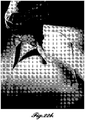
- a non-limiting example of such an array is one that comprises both straight microstructures (i.e., protruding from a base at a 90° angle) and angled microstructures (e.g., protruding from the base at an angle less than 90°, such as 51°).
- individual microstructure length can vary based upon its position in a microstructure array, or based upon its position on a wound closure device.
- the microstructure arrays of the present invention are fashioned or affixed upon a base in a particular shape or pattern, said shape or pattern optionally being of any shape or geometry described herein.
- such patterned arrays are further affixed to a backing (e.g., a flexible and / or stretchable backing); while in other embodiments they are not.
- arrays according to the present disclosure are fashioned or affixed on a base portion, optionally at an angle, wherein the arrays are patterned in a rectangular shape, said arrays comprising microstructures of any shape or geometry described herein; and said arrays optionally being affixed to a backing.
- the wound closure devices of the present invention comprise a plurality of microstructure arrays that are capable of penetrating or grasping skin or tissue; said arrays either being affixed to a flexible and stretchable backing, or being comprised on a single flexible and stretchable base, in a configuration such that at least two arrays are separated by an isthmus, as described herein; and said devices having the capability of being stretched across a wound and secured on either side via the traction or grip of the microstructures. Accordingly, such a device may be applied by first securing at least one microstructure array to the skin or tissue on one side of the wound, then stretching the device across the wound so as to secure another microstructure array to the skin or tissue on the other side of the wound.
- the retractile force of the stretched device can in some embodiments pull and/or secure the wound closed, thus further promoting healing; while in other embodiments such a force stabilizes the position of the device on the skin, but does not directly induce the closure of the wound.
- the wound closure devices of the present invention comprise a plurality of microstructure arrays that are capable of penetrating or grasping skin or tissue; said arrays either being affixed to a non-stretchable backing, or being comprised on a single non-stretchable base, in a configuration such that at least two arrays are separated by an isthmus, as described herein.
- the devices are useful e.g., for securing tissue in place.
- Non-limiting examples of how this type of device may be used include the securing of a wound closed that has already been closed by some other method e.g., via suturing, or with forceps.
- wound closure devices of the present invention may optionally be covered to further protect the lesion from the surrounding environment, and to assist in maintaining proper securing of the device as placed.
- Covers may optionally comprise adhesive.
- the wound closure devices of the present invention may comprise microstructures of various shapes, sizes, and structures. Accordingly, in some embodiments, one or more microstructure arrays are fashioned, optionally upon a base, said microstructures optionally comprising a variety of shapes, sizes, structures, and geometries; and said arrays optionally being affixed to a backing. Certain embodiments provide for microstructures selected from the group consisting of microneedles, microblades, microanchors, microfishscale, micropillars, microhairs, and combinations thereof.
- the wound closure devices of the present invention may comprise microstructure arrays comprising any density of microstructures. In some embodiments, the density of microstructures comprised in an individual array varies from 2 microstructure per array, to more than 1000 microstructures per array. In certain embodiments, the arrays comprise a density of microstructures arrays varying from 1 microstructure per cm 2 to 1000 microstructures per cm 2 . Accordingly, in various embodiments the array pitch is varied from approximately 30 ⁇ m to more than 1 cm
- microstructures comprised in the wound closure devices disclosed herein may be made of any material or mixture of materials.
- the material is a natural material, or a mixture of natural materials; while in other embodiments it is a synthetic material, or a mixture of synthetic materials.
- Still other embodiments provide for microstructures, according to the present disclosure, comprising mixtures of one or more synthetic materials and one or more natural materials.
- microstructures are made of a material selected from a polymer, a metal, a biomaterial, and a combination thereof.
- a microstructure of the present invention is comprised of nanostructures, ( e.g., nanofibers).
- the microstructures are coated with nanostructures (e.g., nanofibers).
- the microstructures are comprised of, or consist essentially of biodegradable materials. In some embodiments this is very important to ensure complications, such as inflammation, tissue damage, and infection, due to broken needles do not occur.
- the microstructures do not comprise biodegradable materials.
- the microstructures comprise biodegradable materials and non-biodegradable materials.
- microstructures of the present invention are comprised of a polymer selected from poly(methyl methacrylate) (PMMA), silicon, and chitin.
- PMMA poly(methyl methacrylate)
- silicon silicon
- chitin a polymer selected from poly(methyl methacrylate) (PMMA), silicon, and chitin.
- the wound closure devices of the present invention may also optionally comprise other components such as, but not limited to, nanostructures (e.g., nanostructure arrays or nanofibers); bioactive compounds (e.g., drugs, therapeutics, hydrogels, healing substances, and combinations thereof), etc.
- the wound closure devices further comprise chitin (e.g., chitin nanofibers).
- the wound closure devices of the present invention further comprise a hydrogel.
- microstructure arrays designed to penetrate the skin to enable delivery of drugs or other therapeutic agents.
- the microstructures are long enough to penetrate the skin, but not deep enough to reach nerve endings that cause pain.
- Some embodiments can incorporate both microstructures coated with drugs as well as microstructures with open internal structure in which drugs can be incorporated.
- the wound closure device is applied to the skin without the use of an applicator or instrument.
- the wound closure device is applied to the skin using an applicator or instrument, such as a forceps or tweezers, to hold the device, or to provide assistance in delivering force during the application of the device over the wound.
- the wound closure devices of the present invention may optionally include adhesive to assist in the application and optionally in the stabilization of the device upon the skin.
- Adhesive may be present on the device in any suitable location.
- the wound closure devices comprise an adhesive backing, or a base that comprises adhesive.
- adhesive is provided to the device on a tab that is attached to at least one end of the device.
- the tab is not part of the device but is attached to the device in order to enable adhesion.
- the device actually remains on the wound, while a tab can be removed.
- the tabs can be added to one or both distal ends of the device.
- adhesive is provided on a tab that is attached to at least one side of the device.
- Still other embodiments provide for devices as described herein comprising adhesive tabs positioned on at least one end and at least one side of the device. These adhesive tabs may be any length, optionally being shorter, longer, or equal in length to any one or more sides of the device. Furthermore, some embodiments provide for adhesive tabs that are removable, e.g ., adhesive tabs comprising perforations that enable the adhesive portion to be easily torn off by hand.
- the adhesive is any medical grade adhesive, such as, e.g., an acrylate (such as, e.g., is used on the Steri-Strips or Steri-Strip S isthmus), or hydrogel-based adhesives that can stick to wet surfaces (e.g., Polyethylene glycol (PEG) hydrogel).
- the adhesive component comprises nanostructures that provide glueless adhesion. Adhesion of a device to skin or tissue induced by such adhesives may last for as little as a minute ( e.g., when the adhesive is utilized to help apply the device) or such adhesion may last for 10 days or more.
- adhesion to the skin or tissue as the result of an adhesive may last for 5 min, 10 min, 15 min, 20 min, 30 min, 60 min, 2 hr, 4 hr, 6 hr, 12 hr, 24 hr, 2 days, 4 days, 6 days, 8 days, 10 days, or more, including all integers (31 min, 32 min, 33 min, 13 hr, 14 hr, 15 hr, 3 day, 5 days, etc.) and ranges (1 min-10 days, 1 min-1 hr, 5 min-20 min, etc.) of the adhesion durations set forth herein.
- Embodiments of the present invention provide for wound closure devices as disclosed herein that are available in a single package comprising only one such device, as well as packages comprising a plurality of said devices.
- the wound closure devices are in the form of a roll, said roll optionally comprising individually wrapped wound closure devices, or alternatively a plurality of wound closure devices that are not individually wrapped.
- the devices are sterile, and are packaged so as to maintain such sterility until being opened.
- the present invention furthermore provides for hand held dispensers that allow for easy application of the wound closure devices of the present invention.
- the dispenser is a roll-on, handheld dispenser, optionally enabling rapid single hand operation.
- Wound closure systems comprise one or more wound closure devices, as described herein, as well as other optional components such as, e.g., one or more cover (optionally comprising adhesive) to be applied over the wound closure device; one or more containers (e.g., bottles, pouches, packets, tubes) comprising a drug or therapeutic which can optionally be applied to the wound prior to the application of the device; cleansing and/or sterilization means (e.g., antiseptics, antibiotics, sterile saline); analgesics (e.g., Benzocaine or Lidocaine); and instructions for using the various components of the wound closure system singly, or in combination.
- cleansing and/or sterilization means e.g., antiseptics, antibiotics, sterile saline
- analgesics e.g., Benzocaine or Lidocaine
- wound closure devices of the present invention are suitable for treating internal and external wounds alike.
- the wound closure devices are applied to a subject's skin; and in other embodiments the wound closure devices are applied to a subject's tissue (e.g., internal tissue).
- the wound closure devices of the present invention find utility in a variety of settings including, but not limited to, the treatment of wounds in urgent care settings (e.g., surgery or trauma centers including emergency rooms, operating rooms, ambulances battlefields, and sites of accidents); in hospitals and clinics; in over the counter settings ( e.g., for use at home).
- the wound closure devices of the present invention have alternative utilities.
- the devices disclosed herein may also be used in cosmetics, wherein microstructures, as described herein, may be used to penetrate the skin producing skin rejuvenation via acute injury resulting in stimulating the dermis and collagen formation inducing effects achieved with cosmetic laser procedures and skin rollers made of microneedles. This achieves improvement in the appearance of the skin by reducing wrinkles and increasing skin volume.
- application of the wound closure devices do not produce symptomatic inflammation resulting in pain, redness, swelling and temporary disfigurement; symptoms which can present for up to a few days after the laser procedure.
- the wound closure devices can be applied to regions of the skin that are not easily accessible to microneedles, such as between the nose and mouth.
- our wound closure devices can be applied and left in place overnight or for days potentially providing more stimulation to the dermis than is achieved with short-term treatment with a microneedle roller.
- the wound closure device generates more uniform distribution of holes in the skin than can be achieved with a microneedle roller which is rolled onto the skin surface.
- wound closure device as used generally means a device used for closing a wound, covering a wound, protecting a wound, a wound dressing, a bandage, etc.
- wound means an injury to tissue or skin caused by a scrapes, cuts, abrasion, surgical procedures (e.g., caused by minimally invasive surgery, laparoscopic surgery, robotic surgery, incisional biopsies, general surgery, and cosmetic surgery), denuded skin, burns, ulcers ( e.g., diabetic ulcers, ulcers from vascular insufficiency, pressure sores, and burns), or other skin problems (e.g., allergies). Wound may range from superficial ( e.g., affecting merely the epidermis) to more traumatic ( e.g., lesions which affect layers of skin or tissue at depths which are beneath the epidermis). Wounds may be of any length or shape, e.g., in some embodiments, wounds are straight, jagged or curved.
- tissue means any human or other animal tissue including, but not limited to skin, muscle, tendon, bone, heart, lung, kidney, brain, bowel, colon, rectum, stomach, esophagus, etc.
- PMMA poly(methyl methacrylate), which is also known as Poly(methyl 2-methylpropenoate (IUPAC name), polymethyl methacrylate, or more commonly known as PlexiglassTM.
- an everted wound refers to a wound that is closed (or at least substantially closed), wherein the wound edge is slightly raised above the normal skin level.
- Wound edge eversion is a common suturing technique to reduce the formation of linear pits and visible scarring.
- the term "grasping" is used herein, to describe a microstructure-based anchoring of a wound closure device to its intended location on the surface of the skin or tissue to which it is applied; said anchoring not requiring penetration into the skin or tissue by the microstructures, but instead e.g., being anchored via friction generated by the contact of the microstructures with the skin or tissue.
- the device is anchored by grasping, optionally with or without the assistance of the other various components of the present wound closure devices and systems, e.g., a protective cover or adhesive.
- penetration or “penetrate” is meant herein to refer to the action of piercing the skin or tissue, e.g ., with one or more of the microstructures disclosed herein.
- inflammation is meant to have its ordinary medical meaning, i.e. a biological response of a tissue to a harmful stimulus. Common signs of inflammation include pain, heat, redness (erythema), swelling (edema), and loss of function.
- the term "base” is meant generally to describe a supporting means from which one or more microstructures protrude.
- the base comprises a plurality of microstructures; and in other embodiments devices comprising singular microstructures on a base are provided.
- the base may be a separate component upon which one or more microstructures are affixed; or alternatively, the microstructures and the base may be one continuous component that are fabricated at the same time, optionally from the same or different materials.
- some embodiments of the present invention provide for wound closure devices comprising one or more microstructure arrays patterned on a base, wherein both the base and the microstructures are made out of PMMA.
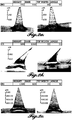
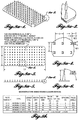
- the microstructures are manufactured using a replica molding technique, wherein both the microstructures and the array are manufactured simultaneously, and are thus in essence one single component (See Figures 1a to If).
- Further embodiments provide for a variety of base specifications including, e.g ., thickness, length, width, and composition.
- the base comprises a substantially planar upper surface and a substantially planar lower surface; said upper surface comprising one or more microstructures, and said lower surface optionally being affixed to a backing.
- the upper surface comprising the microstructures is intended to be put in contact with the skin or tissue of the patient and the lower surface is intended to be exposed to the external environment, or optionally to be in contact with a protective cover, e.g., a cover comprising adhesive.
- arrays and “microstructure array” are used herein to describe a two-dimensional configuration of two or more microstructures on a “base”, as described herein, said base having a substantially planar upper surface from which the microstructures protrude.
- the "array” may be in any suitable shape or pattern, and the array may be of any suitable size or dimensions.
- arrays may comprise any suitable number or density of microstructures, said microstructures optionally extending from the base at angle, or in a substantially perpendicular manner.
- an “array region” as used herein is meant to describe an area of the present devices upon which one or more microstructure arrays are affixed. Accordingly, in some embodiments the array region is a portion of the backing upon which one or more bases are affixed, said bases each comprising one or more microstructure or microstructure arrays. In some particular embodiments, the devices of the present invention comprise at least two "array regions" that are separated from one another by an isthmus, as described herein.
- FIG. 13a to 13e A non-limiting example of such a design is shown in Figures 13a to 13e ; wherein a wound closure device is depicted, said device comprising two array regions, each region comprising one microstructure array affixed to a backing; wherein the two array regions are separated by an isthmus of the exact same width as the backing.
- Figures 15a to 15e Another similar non-limiting example is shown in Figures 15a to 15e , wherein the device comprises two array regions separated by an isthmus with a narrow width compared to the width of the backing upon which the arrays are affixed.
- isthmus refers to a space with no arrays, that separates two or more microstructure “arrays” or “array regions”.
- Isthmus separation refers to the distance separating two arrays on opposing sides of an isthmus.
- the isthmus may comprise any suitable material, and may in some embodiments be rigid, flexible, and/or stretchable.
- the size and shape of the isthmus may vary, and in some embodiments the device will comprise an isthmus and a backing, both being made out of the same material, while in other embodiments the material comprised in the isthmus will differ from that of the backing.
- the isthmus is simply created by affixing two or more microstructure arrays upon a backing such that a space separates the two arrays.
- the isthmus is a portion of a base comprising a plurality of microstructure arrays (i.e., the isthmus and the microstructures are made of the same material).
- Non-limiting examples of two different types of isthmuses can be seen in Figures 13a to 13e and 15a to 15e wherein the shape, composition (silicone vs. thermoplastic polyurethane ("TPU”)), and properties ( i.e. stretchable vs. non-stretchable) have been varied.
- Figures 15a to 15e demonstrate the optional addition of a therapeutic (e.g., 2% Chitosan hydrogel) to the isthmus to further promote wound healing.
- a therapeutic e.g., 2% Chitosan hydrogel
- the isthmus ranges from 1 mm in length to 15 mm in length.
- the devices of the present invention may comprise isthmuses that are 1 mm in length, or they may comprise isthmuses that are 2 mm; 3 mm; 4 mm; 5 mm; 6 mm; 7 mm; 8 mm; 9 mm; 10 mm; 11 mm; 12 mm; 13 mm; 14 mm; or 15 mm in length, including all decimals ( e.g., 1.5 mm, 1.6 mm, 1.7 mm, etc. ) and ranges ( e.g., 1-15 mm, 5-10 mm, 10-15 mm, 3-4 mm, 5-6 mm, 6-8 mm, etc. ) in between, of the isthmus lengths set forth herein.
- decimals e.g., 1.5 mm, 1.6 mm, 1.7 mm, etc.
- ranges e.g., 1-15 mm, 5-10 mm, 10-15 mm, 3-4 mm, 5-6 mm, 6-8 mm, etc.
- the width of the isthmus may vary. In some embodiments the isthmus width is the same as the base or backing of the device. In other embodiments, the isthmus is wider or narrower than the base or backing of the device. Thus, the width of the isthmus may range from as small as 1 mm to as large as 50 cm or more. Accordingly, isthmus widths may range from approximately 1 mm, 2 mm, 3 mm, 4 mm, 5 mm, 6 mm, 7 mm, 8 mm, 9 mm, 1 cm, 2 cm, 3 cm, 4 cm, 5 cm, 10 cm, 20 cm, 30 cm, 40 cm, 50 cm, or longer, including all integers ( e.g., 11 mm, 12 mm, 13 mm, etc. ) and ranges ( e.g., 2 mm-50 cm, 5 mm-15 mm, 5 mm-10 mm, etc. ) in between of the isthmus widths set forth herein.
- integers e.g., 11 mm, 12 mm
- anisotropic positioning refers to variation in the components of individual microstructures comprised in a microstructure array, said microstructures comprising directional variability in their physical properties, e.g ., their aspect ratios or angles of attachment to a backing. In other embodiments, this variability may be in regard to directional differences between different arrays. Anisotropic variability may be in one direction, or in more than one direction.
- microstructure refers to a three-dimensional structure projecting from or connected to a base.
- a microstructure may be an integral part of the base (i.e., the microstructure and base are monolithic).
- the microstructure may be of separate construction than the base but be joined to the base (e.g., through adhesive, bonding, etc.).
- Microstructures typically have dimensions on the micron size scale, although certain dimensions may extend into the millimeter size scale (e.g., length) and certain dimensions may be smaller than one micron (e.g., nano scale tip width).
- microstructures include microneedles, microblades, microanchors, microfishscale, micropillars, and microhairs.
- a microstructure includes a foundation, a tip, and a body joining the foundation with the tip.
- the term "foundation" refers to the two-dimensional area where the base meets the microstructure.
- the foundation may be better understood with reference to Figures 5a and 5c .
- the foundation can be any two-dimensional shape, including a circle, oval, ellipse, triangle, rectangle, square, quadrilateral, or higher-order polygon.
- the term "tip” refers to the end of the microstructure distal to the foundation and base.
- the tip may be a single point (e.g., a needle), a line (e.g., a blade), or other shape.
- the term "body” refers to the portion of the microstructure between the foundation and the tip.
- the body may be better understood with reference to Figures 5a and 5c .
- the body may also be referred to herein as a "shaft” of the microstructure.
- the body has a "length” that is equal to the longest distance connecting a point on the foundation to the tip.
- the microstructure can be either straight or curved.
- the body connects the foundation to the tip without curvature along its length. In other embodiments, the body is curved along its length between the foundation and the tip.
- straight refers to a microstructure having no curvature (i.e., no concave or convex surfaces) along the body between the foundation and the tip. Examples of straight microstructures are illustrated schematically in Figures 4a to 6a and photographically in Figures 2a and 2c .
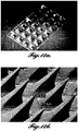
- curved refers to a microstructure having one or more concave or convex surfaces along the body between the foundation and the tip. Examples of curved microstructures are illustrated schematically in Figures 6b and 6d and photographically in Figures 2b , 12a, and 12b .
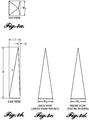
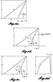
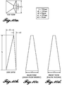
- Straight and curved microstructures can be defined in terms of a "face angle" ( ⁇ F ), which is the smallest angle formed between the base and the microstructure. Referring to the straight microstructure illustrated in Figure 6a , the face angle is constant along the entire body from the foundation to the tip.
- the curved and articulated microstructures in Figures 6b and 6c respectively, include multiple different face angles along the body, as illustrated by comparing Angle ⁇ 1 , formed between the base and tangent T 1 , to Angle ⁇ 2 , formed between the base and tangent T 2 . Angle ⁇ 1 is different than Angle ⁇ 2 .
- the face angle will always be greater than the overall angle of the microstructure.
- the face angle is greater than 90 degrees (e.g., for a straight microstructure at 90 degrees relative to the base). In certain embodiments, the face angle is less than 90 degrees. In one embodiment, the face angle is from 5-90 degrees. In one embodiment, the face angle is from 10-80 degrees. In one embodiment, the face angle is from 20-70 degrees. In one embodiment, the face angle is from 50-70 degrees.
- articulated refers to a microstructure that does not curve continuously but instead curves via one or more joints connecting straight portions.
- An articulated microstructure may also be referred to as “beveled.”
- An articulated microstructure is illustrated in Figure 6c .
- convex refers to a microstructure having at least one line along the outer surface of the body that deviates outwardly from a straight line between the foundation and the tip.
- An exemplary convex microstructure is illustrated in Figure 6d .
- concave refers to a microstructure having at least one line along the outer surface of the body that deviates inwardly from a straight line between the foundation and the tip.
- An exemplary concave microstructure is illustrated in Figure 6b .
- angled refers to a microstructure that is not perpendicular to the base.
- the angle of a microstructure in relation to the base can be understood with reference to Figure 5a , which illustrates a straight microstructure having a line, through the body, connecting the tip to a center point.
- the "center point” is the center of the foundation.
- the angle (“center point angle”; ⁇ c ) formed between the line and the base defines the angle of the entire microstructure.
- microstructures For microstructures, if the tip is not directly above the center point then the microstructure is angled.
- Curved microstructures may be defined by an angle if a tip-to-center point line can be drawn so as to define an angle in relation to the base. However, extensively curved microstructures may not allow a straight line to be drawn through the body from the tip to the center point.
- microneedle is intended to refer to any microstructure comprising straight or tapered shafts.
- the diameter of the microneedle is greatest at the base end of the microneedle and tapers to a point at the end distal the base.
- the microneedle can also be fabricated to have a shaft that includes both a straight (untapered) portion and a tapered portion.
- the microneedles can be formed with shafts that have a circular cross-section in the perpendicular, or the cross-section can be non-circular.
- the cross-section of the microneedle can be polygonal (e.g. star-shaped, square, rectangular, and triangular), oblong, or another shape.
- the tip portion of the microneedles can have a variety of configurations.
- the tips can be symmetrical or asymmetrical about the longitudinal axis of the microneedle shaft.
- the tips are beveled.
- the tip portion is tapered.
- the tapered tip portion is in the shape of a pyramid on a shaft portion having a square cross-section, such that the microneedle is in the shape of an obelisk.
- the tip and/or shaft can be rounded, or have another shape, as well.
- the microneedles comprise a shape that is a e.g., rod, cone, square, rectangle, pyramid, cylinder.
- microblade is intended to refer to a needle-like microstructure comprising a tip that is not a point, but is instead a blade.
- This embodiment is illustrated, for example, in Figures 8a-1 to 8a-6 and 12b , which shows a picture of a microstructure array comprising microblades.
- the tip portion of these structures is wide in a first dimension (50 ⁇ m in this picture) and very narrow in a second dimension, with respect to the first dimension (e.g., less than 10 ⁇ m in this picture)
- the thickness at the tip is smaller than the width of the microblades near their base.
- microanchor is intended to refer to any microstructure capable of anchoring a device according to the present disclosure to skin or tissue.
- microanchors include microstructures with ends shaped like hooks or barbs.
- barb refers to a tip configuration comprising angled portions projecting away from the tip in order to secure the barb within the penetrated skin or tissue.
- microfishscale is intended to refer to any microstructure comprising a scale that partially overlaps, with other scales of microscale dimensions and mimics the scale of a fish.
- micropillar is intended to refer to any microstructure comprising a cylindrical shape.
- microhair is intended to refer to any microstructure comprising hair-like features which enable the contacting and sticking of the microhair to another object via van der Waals forces.
- tapered is meant to describe a microstructure wherein the width or diameter gradually diminishes along the length of the needle from the base to the tip, such that the base comprises the largest width or diameter, and the tip comprises the smallest width or diameter.
- a “partially tapered” microstructure is one in which a portion of the microstructure is tapered and a portion of the microstructure is not tapered.
- such a microstructure can comprise a tapered portion extending from a block shaped base; or e.g., a cylindrical base portion can extend toward the tip for a certain length, and then a tapered portion can continue to the tip.
- the microstructure can comprise a tapered portion extending from the base, with a non-tapered portion being at the tip end of the microstructure.
- stretchable as used herein is meant to encompass any material that can be elongated in any direction, e.g ., as a result of a pulling force.
- Stretchable encompasses the term “elastic” and thus an object that is said to be stretchable should be understood to optionally comprise elasticity.
- an object is said to be stretched, this is meant to include at least two embodiments; the first being that the stretching force will be counteracted by a retractile force, and thus once the stretching force is removed, the object will inherently attempt to retract ( e.g., as is the case with an elastic object).
- the second embodiment is one in which the object does not inherently comprise elasticity, and thus no such retractile force is inherent.
- a “flexible” material comprises enough flexibility as to allow the device of the present invention to bend so as to fit the contours of the biological barrier, such as, e.g., the skin, vessel walls, or the eye, to which the device is applied.
- backing as used herein, is meant to describe an optional component of the present wound closure devices which is attached to one or more arrays.
- the backing attaches two or more microstructure arrays together.
- the backing may comprise any suitable material, and in several embodiments it is flexible, stretchable, elastic, or combinations thereof.
- cover as used herein in meant to describe an optional component of the wound closure systems disclosed herein whereby it covers the wound. After application of the wound closure devices of the present invention, such a cover may be optionally applied over and/or attached to the top of the device, e.g ., assist in securing the device in place.
- the covers may be made of any suitable material, as is discussed and defined thoroughly in the detailed description section below. In some embodiments the covers comprise adhesive.
- one or more microstructures are "affixed to a backing” it is meant that the microstructures may optionally be either directly affixed to the backing, or indirectly affixed to the backing ( e.g., in some embodiments, "affixed to a backing” is meant to encompass the scenario wherein the microstructures are fashioned on, or affixed to, a base, said base being affixed to a backing). Accordingly, the phrase “one or more microstructures affixed to a backing” can appropriately be used interchangeably with the phrase "a backing comprising one or more microstructures.”
- the term "pitch" is meant to describe the distance between the tips of two or more adjacent microstructures in a given array, or in two or more separate arrays. In some embodiments the pitch ranges from 30 ⁇ m to 1 cm or more. Accordingly, certain embodiments provide for microstructure arrays as disclosed herein, wherein the microstructures are separated from one another with a pitch of 30 ⁇ m, 50 ⁇ m, 70 ⁇ m, 90 ⁇ m, 100 ⁇ m, 150 ⁇ m, 200 ⁇ m, 250 ⁇ m, 300 ⁇ m, 350 ⁇ m, 400 ⁇ m, 450 ⁇ m, 500 ⁇ m, 550 ⁇ m, 600 ⁇ m, 650 ⁇ m, 700 ⁇ m, 750 ⁇ m, 800 ⁇ m, 850 ⁇ m, 900 ⁇ m, 950 ⁇ m, 1 mm, 1.1 mm, 1.2 mm, 1.3 mm, 1.4 mm, 1.5 mm, 2 mm, 2.5 mm, 3 mm, 3.5
- the pitch may be constant throughout an array, e.g., an equal distance separates all microstructure tips from one another in a given array; or the pitch may vary.
- Draize score refers to a score according to the Draize scale, which is a standard scoring system used to measure skin toxicities of devices and drugs.
- the term “adhesive” or “glue” are used interchangeably. These terms are meant to have their ordinary meaning, e.g ., any substance that is capable of binding two or more materials together.
- the adhesive is intended to be used on the skin.
- the adhesive may be a medical grade adhesive such as, e.g., an acrylate (such as, e.g., are used on the Steri-Strips or Steri-Strip S isthmus), or hydrogel based adhesives that can stick to wet surfaces (e.g. Polyethylene glycol (PEG) hydrogel).
- the adhesive component comprises nanostructures that provide glueless adhesion.
- applicator as used herein is meant to describe any machine or instrument that is used to affix a wound closure device, e.g., to the skin or tissue surrounding a wound. Accordingly, the use of medical instruments such as forceps, tweezers, clamps, pins, etc., to apply such a device would be considered to be use of an applicator.
- applicator also refers to the roll on hand held dispenser disclosed herein. Thus, when it is said that the device is applied without an applicator, this is to be understood as being applied by human hand, without the aid of a machine or instrument.
- microstructures comprised in the wound closure devices disclosed herein may be made of any material or mixture of materials.
- the material is a natural material, or a mixture of natural materials; while in other embodiments it is a synthetic material, or a mixture of synthetic materials.
- the microstructures are comprised of nontoxic, biodegradable, bioresorbable, or biocompatible materials, or combinations thereof; and in other embodiments they are not. Still other embodiments provide for microstructures, according to the present disclosure, comprising mixtures of one or more synthetic materials and one or more natural materials.
- microstructures are made of a material selected from a polymer, a metal, a biomaterial, and a combination thereof.
- microstructures of the present invention are comprised of a material selected from the group consisting of PMMA, silicone, chitin, chitosan, ecoflex, titanium, glass, metal, steel, silicon, silk, catgut, chromic catgut, polyglycolic acid, polydioxanone, polytrimethulene carbonate, nylon, polypropylene, polyester, polybutester, poly(lactic-co-glycolic acid), polylactone, elastin, resilin, collagen, cellulose, and any combination thereof.
- a material selected from the group consisting of PMMA, silicone, chitin, chitosan, ecoflex, titanium, glass, metal, steel, silicon, silk, catgut, chromic catgut, polyglycolic acid, polydioxanone, polytrimethulene carbonate, nylon, polypropylene, polyester, polybutester, poly(lactic-co-glycolic acid), polylactone, elastin, resilin, collagen
- Embodiments of the present invention provide for microstructures selected from the group consisting of microneedles, microblades, microanchors, microfishscale, micropillars, microhairs, and combinations thereof.
- Microstructures may be designed to be able to penetrate into skin or tissue, or they may be designed to merely grasp skin or tissue without actual penetration.
- the microstructures are designed to penetrate the skin or tissue to specific depths, e.g ., through the epidermal or dermal layers, or to the various sublayers thereof.
- microstructures of any desired size, dimension, and geometry may optionally comprise surfaces which are substantially smooth, or which comprise uneven surfaces, e.g ., a microstructure comprising sides which are wavy, or which comprise protrusions, indentations, or depressions.
- the microstructure includes a foundation adjacent to a base, a tip, and a body connecting the foundation to the tip.
- a line extending from the tip perpendicular to the base does not pass through the foundation.
- Angled and/or curved microstructures may have a shape that positions the tip beyond the foundation. Examples of such microstructures are illustrated schematically in Figure 5a and photographically in Figure 2b . Additionally, it will be appreciated that any microstructure, no matter the body shape, angle, and/or curvature, that has a tip position as described is contemplated by the present embodiment.
- a line extending from the tip perpendicular to the base passes through the foundation.
- Angled and/or curved microstructures may have a shape that positions the tip within the perimeter of the foundation. Examples of this microstructure configuration are illustrated schematically in Figure 5b and photographically in Figure 2a . Additionally, it will be appreciated that any microstructure, no matter the body shape, angle, and/or curvature, that has a tip position as described is contemplated by the present embodiment.
- an angle between the body and the base is a constant angle.
- the center point angle and the face angle are constant.
- Figures 5a and 6a are examples of such a microstructure.
- two or more different angles are formed between the body and the base between the foundation and the tip.
- Curved or articulated microstructures are examples of such a microstructure.
- Figures 6b and 6c are examples of such a microstructure.
- the body of the microstructures can have concave surfaces, convex surfaces, and a combination of concave and convex surfaces.
- the body comprises at least one concave surface.
- the body comprises at least one convex surface.
- the body comprises at least one concave surface and at least one convex surface.
- the microstructures comprise microneedles.
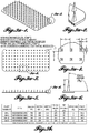
- Microneedles narrow from a foundation to a tip. Representative microneedles are illustrated in Figures 3a-1 to 3a-6 .
- each microneedle includes a foundation that has a width (W1) and thickness (T). While the microneedles illustrated in Figures 3a-1 to 3a-6 have rectangular foundations, it will be appreciated that this is only one embodiment of the microneedles. Other embodiments include microneedle foundations that are circular, oval, triangular, square, higher-order polygons, and combinations thereof.
- the tip of the microneedle extends a length (L) from the foundation.
- the tip can also be offset a distance (D) such that the tip is not centered vertically above the foundation.
- the tip is centered vertically above the center point of the foundation. In other embodiments, the tip is positioned vertically above a point on the perimeter of the foundation.
- the tip of a microneedle converges to a single point, the tip has some diameter as a result of fabrication.
- each microneedle has a face angle ( ⁇ F) formed between a side wall of the microneedle and the surface supporting the microneedle.
- the microstructures comprise microblades.
- Microblades narrow from a foundation to a tip. Representative microblades are illustrated in Figures 8a-1 to 3a-6 .
- each microblade includes a foundation that has a width (W1) and thickness (T). While the microblades illustrated in Figures 3a-1 to 3a-6 have rectangular foundations, it will be appreciated that this is only one embodiment of the microblades. Other embodiments include microblade foundations that are circular, oval, triangular, square, higher-order polygons, and combinations thereof.
- the tip of the microblade extends a length (L) from the foundation.
- the tip can also be offset a distance (D) such that the tip is not centered vertically above the foundation.
- the tip is centered vertically above the center point of the foundation. In other embodiments, the tip is positioned vertically above a point on the perimeter of the foundation.
- a microblade Unlike a microneedle, a microblade has a tip that forms a line, not a single point.
- the microblade tip has a width (W2) and a nominal thickness.
- each microblade has a face angle formed between a side wall of the microblade and the surface supporting the microblade.
- Microneedles and microblades interact with the skin of a patient in different ways, given their different characteristics. For example, microblades provide more surface area than microneedles of the same length and width. By providing a larger surface area, microblades are able to remain anchored to the skin with higher lateral tension than microneedles. Consequently, a smaller number of microblades can be used to close a wound under tension than can be achieved with microneedles.
- Microstructures may have heights ranging from approximately 1 ⁇ m to approximately 3 mm. Thus, microstructures may have heights of approximately 1 ⁇ m, 10 ⁇ m, 50 ⁇ m, 100 ⁇ m, 150 ⁇ m, 200 ⁇ m, 250 ⁇ m, 300 ⁇ m, 350 ⁇ m, 400 ⁇ m, 450 ⁇ m, 500 ⁇ m, 550 ⁇ m, 600 ⁇ m, 650 ⁇ m, 700 ⁇ m, 750 ⁇ m, 800 ⁇ m, 850 ⁇ m, 900 ⁇ m, 950 ⁇ m, 1 mm, 1.5 mm, 2 mm, 3 mm, or higher, including all integers ( e.g., 2 ⁇ m, 3 ⁇ m, 4 ⁇ m, etc.
- the microstructure arrays of the present invention may comprise individual microstructures that have heights of approximately 1 ⁇ m up to approximately 3 mm, as described above. Longer (e.g., 3 mm or longer) microstructures are needed for treatment areas that include thicker dermal tissue (e.g., the back).
- Microstructures may have widths or diameters, as measured by the area meeting the foundation of the base, ranging from approximately 15 ⁇ m up to approximately 2 mm ( e.g., see Width 'W1' in Figures 8a-4 ). Thus, microstructures may have widths or diameters of approximately 15 ⁇ m, 30 ⁇ m, 50 ⁇ m, 100 ⁇ m, 150 ⁇ m, 200 ⁇ m, 250 ⁇ m, 300 ⁇ m, 350 ⁇ m, 400 ⁇ m, 450 ⁇ m, 500 ⁇ m, 550 ⁇ m, 600 ⁇ m, 650 ⁇ m, 700 ⁇ m, 750 ⁇ m, 800 ⁇ m, 850 ⁇ m, 900 ⁇ m, 950 ⁇ m, 1 mm, 1.5 mm, 2 mm, or wider, including all integers ( e.g., 101 ⁇ m, 102 ⁇ m, 103 ⁇ m, etc.
- the microstructure arrays of the present invention may comprise individual microstructures that have widths or diameters of at least or approximately 15 ⁇ m up to approximately 2 mm, as described above.
- Microstructures may have tips with widths or diameters of approximately 10 nm up to approximately 50 ⁇ m ( e.g., see Width 'W2' in Figures 8a-4 ).
- microstructures may have tips with a width or diameter of approximately 10 nm, 20 nm, 30 nm, 40 nm, 50 nm, 60 nm, 70 nm, 80 nm, 90 nm, 100 nm, 125 nm, 150 nm, 175 nm, 200 nm, 300 nm, 400 nm, 500 nm, 600 nm, 700 nm, 800 nm, 900 nm, 1 ⁇ m, 5 ⁇ m, 10 ⁇ m, 15 ⁇ m, 20 ⁇ m, 25 ⁇ m, 30 ⁇ m, 35 ⁇ m, 40 ⁇ m, 45 ⁇ m, 50 ⁇ m, or wider, including all integers ( e.g., 11 nm, 12 nm, 13
- a microstructure includes a tip offset (D)
- the offset can be from 1 nm to one-half the thickness (T) or width (W1) of the foundation of the microstructure.
- the tip offset is from 20% to 33% of the thickness of the foundation of the microstructure.
- Bases which may optionally comprise the various microstructures and microstructure arrays, may be made of any suitable material.
- the base may be transparent or substantially transparent ( e.g., to enable non-invasive wound observation) or alternatively, it is not transparent ( e.g., to hide the wound).
- the base may optionally comprise nontoxic, biodegradable, bioresorbable, or biocompatible materials, or combinations thereof.
- the base may be made out of the same material as the microstructures it comprises, or it may be made of a different material.
- microstructure bases comprising any material or mixture of materials.
- the material is a natural material, or a mixture of natural materials; while in other embodiments it is a synthetic material, or a mixture of synthetic materials.
- microstructure bases comprising mixtures of one or more synthetic materials and one or more natural materials.
- microstructure bases are made of a material selected from a polymer, a metal, a biomaterial, a hydrogel, a glass, and a combination thereof.
- microstructure bases of the present invention are comprised of a material selected from the group consisting of PMMA, silicone, chitin, chitosan, titanium, glass, metal, steel, silicon, silk, catgut, chromic catgut, polyglycolic acid, polydioxanone, polytrimethulene carbonate, nylon, polypropylene, polyester, polybutester, poly(lactic-co-glycolic acid), elastin, resilin, collagen, cellulose, and any combination thereof.
- a material selected from the group consisting of PMMA, silicone, chitin, chitosan, titanium, glass, metal, steel, silicon, silk, catgut, chromic catgut, polyglycolic acid, polydioxanone, polytrimethulene carbonate, nylon, polypropylene, polyester, polybutester, poly(lactic-co-glycolic acid), elastin, resilin, collagen, cellulose, and any combination thereof.
- the microstructures and the bases are both comprised of PMMA. In another certain embodiment, the microstructures and the bases are both comprised of silicone.
- the thickness of the base may be substantially uniform throughout the device, or alternatively it may be varied.
- the thickness of the base is determined by the material that it is made out of, e.g., a 1 mm thickness for a silicone base may be used, as this material comprises acceptable flexibility at such a thickness; a base comprising PMMA, on the other hand may be fashioned at approximately 125 ⁇ m or less thick in some instances, so as to maintain some degree of flexibility.
- a PMMA base may be thicker, e.g., 300 ⁇ m thick, if a stiffer base is desired.
- One skilled in the art can easily determine the appropriate thickness of a base depending on the material from which it is made, and the desired flexibility or lack thereof of the base.
- the thickness of the base ranges from approximately 10 ⁇ m to approximately 1 mm.
- the base thickness is approximately 10 ⁇ m, 20 ⁇ m, 30 ⁇ m, 40 ⁇ m, 50 ⁇ m, 60 ⁇ m, 70 ⁇ m, 80 ⁇ m, 90 ⁇ m, 100 ⁇ m, 125 ⁇ m, 150 ⁇ m, 175 ⁇ m, 200 ⁇ m, 300 ⁇ m, 400 ⁇ m, 500 ⁇ m, 600 ⁇ m, 700 ⁇ m, 800 ⁇ m, 900 ⁇ m, 1 mm or thicker, including all integers ( e.g., 126 ⁇ m, 127 ⁇ m 128 ⁇ m, etc. ) and ranges ( e.g., 50 ⁇ m-200 ⁇ m, 100-160 ⁇ m, 120-140 ⁇ m, etc. ) in between, of the microstructure base thicknesses set forth.
- Bases may be as long or wide as is necessary to comprise the desired microstructure array or arrays.
- the dimension of a base may be as small as 1 mm wide in the dimension perpendicular to the wound, so as to have one set of microstructures parallel to the wound; and this dimension may range as wide as 10 cm or larger.
- the bases can range from 2 mm, to as large as 50 cm long or more ( e.g., as is optionally the case in some of the microstructure array roll bandages disclosed herein).
- base lengths may range from approximately 2 mm, 5 mm, 10 mm, 2 cm, 3 cm, 4 cm, 5 cm, 10 cm, 20 cm, 30 cm, 40 cm, 50 cm, or longer, including all integers ( e.g., 11 mm, 12 mm, 13 mm, etc.
- base widths may range from approximately 1 mm, 3 mm, 5 mm, 7 mm, 9 mm, 1 cm, 2 cm, 3 cm, 4 cm, 5 cm, 10 cm, or longer, including all integers ( e.g., 11 mm, 12 mm, 13 mm, etc. ) and ranges ( e.g., 1 mm-10 cm, 2 mm-10 mm, 5 mm-10 mm, etc. ) in between, of the base lengths perpendicular to the wound set forth, as described herein.
- the wound closure devices of the present invention comprise microstructures at an angle relative to the backing or base.
- the microstructures may be positioned at any suitable angle. In some embodiments they are affixed at an angle relative to a backing or base, wherein the angle is approximately 15, 30, 45, 60, 75, or 90 degrees, including all integers ( e.g., 16°, 17°, 18°, etc. ) and ranges ( e.g., 15°-90°, 30°-90°, 45°-70°, etc .) in between, of the angles set forth.
- the microstructures are at an angle of greater than 50 degrees relative to the backing or base. In one embodiment, the microstructures are at an angle of from 45 to 70 degrees relative to the backing or base. In one embodiment, the microstructures are at an angle of from 50 to 70 degrees relative to the backing or base.
- the wound closure devices of the present invention also include microstructures with an angle relative to the backing or base that is variable depending on its position in any microstructure array.
- the angle of one or more microstructures is approximately constant along the entire length of the microstructure, and in other embodiments, the angle of the microstructure varies along the length of the microstructure.
- Microstructures may be angled in any direction. In some embodiments, all microstructures in a particular array are angled in the same direction, or in approximately the same direction; while in other embodiments they are not. In certain embodiments, microstructures on a device are angled towards a wound. In some particular embodiments, the microstructures in an array comprise subsets of microstructures angled in different directions.
- the wound closure devices of the present invention may comprise microstructure arrays patterned on one or more bases in a variety of shapes and dimensions.
- Figures 3a-1 to 3a-6 and 8a-1 to 8a-6 show schematic designs of several arrays we have produced.
- the details of exemplary microneedles ( Figure 3b ) and microblades ( Figure 8b ) are provided in a table.
- photographs of one such microneedle array and microblade arrays are provided in Figures 7a and 7b , and Figures 12a and 12b , respectively.
- devices of the present invention may comprise arrays in which the length or width of an array is designed to enable treatment of specific wound types or sizes.
- the dimension of an array that runs parallel to a wound can be as wide as 50 cm e.g., to treat a 50 cm long straight wound; or, alternatively it can be as narrow 2 mm wide, e.g., to treat a 2 to 5 mm long wound.
- the length of the other dimension of an array i.e., the dimension that runs perpendicular to the wound
- the dimensions of an individual array may comprise lengths and/or widths of 1 mm, or they may comprise lengths and/or widths of 2 mm, 3 mm, 5 mm, 7 mm, 9 mm, 10 mm, 2 cm, 3 cm, 4 cm, 5 cm, 10 cm, 15 cm, 25 cm, 50 cm, or more, including all integers ( e.g., 11 cm, 12 cm, 13 cm, etc. ) and ranges ( e.g., 3 mm-50 cm, 9 mm-5 cm, 1 cm-50 cm, etc. ) in between, of the microstructure array lengths and widths set forth.
- the microstructure arrays may comprise any appropriate number of microstructures. In some embodiments, the number of microstructures comprised in an individual array varies from 1 microstructure per array, to more than 1000 microstructures per array.
- the microstructure arrays may comprise any density of microstructures. In some embodiments, the density of microstructures comprised in an individual array varies from 1 microstructure per cm 2 , to 1000 microstructures per cm 2 . In one embodiment, the density of microstructures comprised in an individual array is from 1 to 100 per cm 2 . In one embodiment, the density of microstructures comprised in an individual array is from 5 to 50 per cm 2 . In one embodiment, the density of microstructures comprised in an individual array is from 10 to 20 per cm 2 . In one embodiment, the density of microstructures comprised in an individual array is from 5 to 10 per cm 2 .
- the density of microstructures in an array is decreased to reduce or eliminate the induction of an inflammatory response to the wound closure device.
- arrays comprising lower densities of microstructures e.g., see Figure 7a and Figure 12a
- arrays with higher microstructure densities e.g., see Example 3
- the microstructure arrays of the present invention comprise microstructures patterned in a variety of shapes or patterns. Any shape or pattern of microstructure arrays is within the scope of the present invention.
- the array patterning comprises straight edges.
- the arrays are patterned with rounded edges.
- the array patterning comprises shapes with both rounded and straight edges.
- arrays are patterned in a shape selected from the group consisting of oval, diamond, pyramid, and circle.
- arrays are patterned in a rectangular shape.
- arrays are patterned in the shape of a square.
- arrays comprise pluralities of microstructures that are pattern into separate shapes, wherein two or more regions of the array comprise a higher density of microstructures than the other regions of the array.
- arrays Take for example, but not to be limited in any way, a single square shaped array, which may in one embodiment comprise e.g ., groups of microstructures in any locale, such as, one group in each of the corners of the array, wherein the four microstructure groups are separated by a region of the array that does not comprise any microstructures, or optionally comprises microstructures at a different density than the density of the microstructures comprised in one of the groups.
- a wound closure device that is made up of a single base comprising a single microstructure array, wherein the base comprises a shape that is similar as the device shown in Figures 15a to 15e .
- a base comprises group of microstructures on one end of the device and another group on the other end of the device, such that the groups are separated by a space that does not comprise any microstructures.
- the individual microstructures are distributed uniformly throughout an individual array, and in other embodiments the microstructures are not distributed evenly throughout an array.
- distribution of the individual microstructures may be constant between different arrays (e.g., all arrays comprising uniformly distributed microstructures), or they may be varied between arrays ( e.g., some arrays comprising uniformly distributed microstructures), and other arrays comprising microstructures distributed in a non-uniform manner.
- the size, dimension, and geometry of the microstructures are constant throughout an individual array, while in other embodiments these properties are varied, e.g ., anisotropically. Additionally, in certain embodiments wherein the devices comprise a plurality of arrays, these physical properties may be constant between different arrays ( e.g., all arrays comprising identical designs), or they may be varied ( e.g., different arrays optionally comprising different designs). Accordingly, some embodiments provide for wound closure devices comprising arrays that are homogeneous with regard to the microstructures they comprise; while other embodiments provide for wound closure devices comprising arrays that are heterogeneous with regard to the microstructures they comprise.
- the devices comprise two different microstructure arrays, said arrays comprising angled microstructures; wherein the microstructures from one array are angled toward the microstructures of the other array, and vice versa.
- an isthmus may separate the two different microstructure arrays, such that the arrays are angled towards a wound onto which the device is applied (e.g., if the isthmus is positioned above the wound).
- angles of the opposing microstructures comprised in the separate arrays may be the same (e.g., both arrays comprising microstructures that are angled towards the microstructures of the other array at e.g ., approximately 45°), substantially the same, or they may be different.
- another embodiment provides for a wound closure device comprising more than two microstructure arrays, wherein at least two of said arrays are angled towards one another as described above.
- opposing arrays that are angled towards each other may be located in the same array region ( i.e., they are not separated by an isthmus).
- opposing arrays that are angled towards each other may be located in different array regions ( i.e., they are separated by an isthmus).
- the arrays have an aspect ratio defined in relation to the position on the device to be positioned above a wound (e.g., the isthmus).
- the length is defined as the dimension of the array extending perpendicularly away from the wound.
- the width is defined as the dimension of the array extending parallel to the wound.
- the aspect ratio of the array is from 0.1 to 10.
- the aspect ratio of the array is from 0.4 to 3.
- the aspect ratio of the array is from 1 to 5.
- the aspect ratio of the array is from 2 to 3.
- microstructures comprised in the wound closure devices disclosed herein may be manufactured using any method available to the skilled artisan.
- the microstructures are made by microfabrication processes that are based on established methods e.g ., those used to make integrated circuits, electronic packages and other microelectronic devices, augmented by additional methods used in the field of micromachining and micromolding.
- Arrays of microstructures can be fabricated, e.g ., using combinations of replica molding; injection molding; micro lithography; die cutting and etching; cutting; laser cutting; etching such as have been described, e.g ., in WO2007127976A2 ; WO2002072189A2 ; WO2002064193A2 ; US Pat. Nos. 6,503,231 and 6,334,856 , WO1999064580 and WO2000074763 ; WO2012167162 , all of which are incorporated herein by reference.
- microstructures can be fabricated by (i) etching the microstructure directly, (ii) etching a mold and then filling the mold with a melt or solution comprising the microstructure material to form the microstructure product, or (iii) etching a microstructure master, using the master to make a mold, and then filling the mold to form the microstructure replica (of the master).
- the microstructures are manufactured according to the technique outlined in Figures 1a to If and described in Example 1. Briefly, a master of the desired dimensions is made with a metal, silicon, or a polymer via micromachining, microlithography, etching, laser cutting, or a combination thereof.
- the master is replicated using a polymeric material - e.g ., silicone.
- the silicone is then lifted out of the master and is filled with a solution or a melt of the microneedle material, the filling may occur by e.g., drop casting or spraying. After curing or drying of the solution or melt the microneedles are lifted out from the mold.
- Embodiments of the present invention relate to wound closure devices comprising one or more of a variety of microstructures, said microstructures optionally being affixed to a backing.
- one or more microstructure arrays are affixed to a backing, said microstructures optionally comprising a variety of sizes, dimensions, and geometries.
- Any suitably backing may be used in the fabrication of the present devices, and in some embodiments the backing is optionally flexible and/or stretchable.
- the backing is a separate component, upon which the microstructures are affixed, e.g., via attachment of a base that comprises one or more microstructures, or via direct attachment of one or more individual microstructures onto the backing.
- Such a base typically comprises two substantially planar surfaces, i.e ., an upper surface and a lower surface; wherein one or more microstructures protrude perpendicularly or at an angle from the upper of said surfaces, and the lower of said surfaces is substantially flat.
- the backing may be affixed to the lower surface by any suitable means, e.g ., by gluing.
- the wound closure devices of the present invention may be provided with or without a backing attached.
- the devices of the present invention may be provided in a ready to use form, wherein one or more microstructure arrays are affixed to a backing according to the present disclosure.
- some of the wound closure devices of the present invention do not comprise a backing, but instead comprise one or more microstructures or microstructure arrays on a suitable base, e.g., a base comprising flexibility, stretchability, or flexibility and stretchability, such that the device can perform its intended function on its own.
- a wound closure device may be packaged for commercial use with one or more suitable unattached backings, said backings optionally comprising different shapes, sizes, or compositions, such that one or more appropriately sized backings may be selected specifically to treat a certain type of wound.
- One or more microstructure arrays, provided in such a package may then be attached to the backing as needed, to generate a wound specific device.
- such a device may optionally come with one or more attachment means, such as, e.g., an adhesive; wherein the attachment means may optionally be comprised on one or more components of the device, or it may be provided separately, e.g ., in a package or container.
- Suitable backing for use in the present devices include those which are transparent, or substantially transparent, thus allowing for non-invasive monitoring of wound healing, as well as backings that are not transparent.
- backings are in the form of sheets; bandages; rolls; films; cloths; woven materials; or other permeable, semi-permeable, or impermeable coverings.
- the backings may be made from natural, synthetic, and/or artificial materials; and in some particular embodiments, they comprise a polymeric substance (e.g., a silicone, a polyurethane, or a polyethylene).
- the backing may comprised of materials that are nontoxic, biodegradable, bioresorbable, or biocompatible.
- the backing comprises inert materials, and in other embodiments, the backing comprises activated materials, (e.g., a ctivated carbon cloth to remove microbes, as disclosed in WO2013028966A2 ).
- the backing further comprises elastic properties, wherein the elasticity may optionally be similar throughout the device, or it may be varied along or across the device.
- the backing comprises a material singularly, or in combination, selected from the group consisting of medical tape, white cloth tape, surgical tape, tan cloth medical tape, silk surgical tape, clear tape, hypoallergenic tape, silicone, elastic silicone, polyurethane, elastic polyurethane, polyethylene, elastic polyethylene, rubber, latex, Gore-Tex, plastic and plastic components, polymers, biopolymers, and natural materials.
- the present invention comprises a wound closure device, as disclosed herein, comprising one or more microstructures affixed to a commercially available backing selected from the group consisting of 3M Transpore Surgical Tape, 3M Blenderm Surgical Tape, Coverlet Fabric, Dynarex Silk Surgical Tape, KendallTM Hypoallergenic Clear Tape, TenderfixTM Hypoallergenic Cloth Tape, CurasilkTM Cloth Tape, Curapont, Leukosan Skinlink, Leukosan Strip, Leukostrip, Steri-Strip, Steri-Strip S, Urgo strip, and combinations thereof.
- a wound closure device as disclosed herein, comprising one or more microstructures affixed to a commercially available backing selected from the group consisting of 3M Transpore Surgical Tape, 3M Blenderm Surgical Tape, Coverlet Fabric, Dynarex Silk Surgical Tape, KendallTM Hypoallergenic Clear Tape, TenderfixTM Hypoallergenic Cloth Tape, CurasilkTM Cloth Tape, Cur
- the wound closure devices of the present invention comprise one or more microstructures as described herein.
- the devices may have any suitable or desirable shape, size, or configuration.
- devices of the present invention may in some embodiments have singularly, or in combination, a square, rectangular, round, oval, butterflied, or other shape; and in some embodiments, they may include sheets, tapes, rolls, or covers that can be cut or wrapped around, for example, a portion of a limb, to cover a wound on the limb.
- the devices comprise generic features, according to the present specification, that enable the closure of a wide variety of wounds.
- the devices comprise microstructures 700 microns to 1 mm in length.
- the devices comprise microstructures that are 200 microns to 400 microns in width.
- the devices comprise microstructures at angles of 40 degrees to 60 degrees.
- the devices comprise arrays with a density of 10 to 100 microstructures per cm 2 .
- components of the various devices are designed, accordingly to the specifications disclosed herein, to specifically optimize a device for treating a particular wound, tissue type, or location of the body.
- various specifications e.g ., the microstructure type, geometry, size, specifications, spacing within an array, array structure, number of arrays, location of arrays, dimension of arrays, isthmus, materials of the various components, etc.
- a wound closure device e.g., to treat a specific type of wound, or for treatment of any wound located on a particular type of tissue or location on the patient.
- treatment of wounds on the palm or back may need longer needles than would be required to treat a wound on the face, due to the inherent variety of skin thickness that exists in these (and other) different sites of the body.
- the treatment of wounds may require shorter needles in patients, who are elderly or have chronic medical conditions or skin conditions, or patients treated with drugs, such as steroids, that are known to result in thinning of the skin.
- the wound closure devices may comprise any suitable shape and size to adequately cover a variety of wounds.
- the devices may be of any length or width suitable to cover a single wound, or optionally a plurality of wounds (such as, e.g., a tape bandage).
- the devices have an aspect ratio defined in relation to the position on the device to be positioned above a wound (e.g., the isthmus).
- the length is defined as the dimension of the device extending perpendicularly away from the wound.
- the width is defined as the dimension of the device extending parallel to the wound.
- the aspect ratio of the device is from 0.1 to 10.
- the aspect ratio of the device is from 0.4 to 3.
- the aspect ratio of the device is from 1 to 5.
- the aspect ratio of the device is from 2 to 3.
- Wound closure devices are removed when the wound is closed and shows sufficient healing. This varies for different body sites, such that sutures and other devices are removed 3-5 days, 6-10, and 11-14 days on the head (including face and neck), extremities, and trunk, respectively. Unexpectedly, it has been determined that the wound closure microneedle prototype devices led to accelerated healing of wounds compared to closure of wounds with sutures. See Example 5. More rapid closure of healing is beneficial to patients because it decreases the risks of infection, wound dehiscence, and other adverse events, and also enables patients to return to activities of daily living at an earlier time. In addition, accelerated healing is of benefit to patients with chronic medical conditions or skin conditions, or patients treated with drugs, such as steroids, that are associated with delayed healing of wounds.
- the wound closure devices of the present invention be sterile prior to application to the skin or tissue. Accordingly, in one embodiment, the wound closure devices are sterile when packaged. In another embodiment, the wound closure devices are sterilized immediately prior to use. Many suitable means of sterilization are known and common in the art, and any such means is suitable for sterilizing the wound closure devices, provided said sterilization does not destroy the device. Such means may include, but are not limited to sterilization by heat, radiation, or chemical agents.
- a plurality of wound closure devices may be connected to one another such that more than one of the devices can be applied to a wound at the same time.
- a connection may be at any suitable location on the device, and will of course vary depending on shape and intended use of the particular device.
- a non-limiting example of such an arrangement includes, e.g., a plurality of rectangular-shaped devices connected together via one or both sides that run perpendicular to the wound; such that a plurality of connected wound closure devices may be applied simultaneously in parallel, wherein each device is situated perpendicular to the wound, and the plurality of devices extends along the longitudinal axis of the wound like railroad ties along a track.
- the devices of the present invention may optionally comprise adhesives to assist in the application of the device, and/or to help maintain the device in the position that it is applied to.
- the devices may comprise adhesive which binds a microstructure array to a backing e.g., via the direct binding of a base portion to a backing, as is described more thoroughly in the "backing" section.
- adhesives may be the same throughout the device, or more than one adhesive may be comprised in the device, e.g., one adhesive may be used to bind an array to the backing, and another adhesive may be used to bind the device to the skin or tissue of a patient.
- adhesive covers may be used, wherein the adhesive may again be the same as the adhesive that is optionally comprised on the other various components of the device, or wherein the covers comprise a different adhesive than the other various components of the device.
- the devices may comprise one or more types of adhesives.
- the device is a single base comprising a plurality, of microstructures fashioned into one or more arrays.
- the microstructures may be evenly spaced throughout an array, or they may be unevenly spaced, e.g., one non-limiting embodiment comprises a single base comprising at least two arrays, wherein the arrays are separated by an isthmus.
- the device may comprise one or more bases; each base comprising a plurality of microstructures fashioned into one or more arrays; wherein the bases are attached to a backing according to the present disclosure.
- the microstructures are affixed to a backing or base, e.g., via attachment of the individual microstructures.
- the wound closure devices of the present invention comprise only one microstructure array. In one embodiment, the wound closure devices comprise two microstructure arrays (e.g., separated by an isthmus). In certain embodiment, the wound closure devices comprise a plurality of microstructure arrays. In particular embodiments, the wound closure devices comprise from two to 100 microstructure arrays.
- array spacing may be separated from one another by any appropriate spacing, which may or may not be the same throughout the device.
- array spacing ranges from approximately 30 ⁇ m to 1 cm. Accordingly, array spacing may be approximately 30 ⁇ m, 50 ⁇ m, 100 ⁇ m, 150 ⁇ m, 200 ⁇ m, 250 ⁇ m, 300 ⁇ m, 350 ⁇ m, 400 ⁇ m, 450 ⁇ m, 500 ⁇ m, 550 ⁇ m, 600 ⁇ m, 650 ⁇ m, 700 ⁇ m, 750 ⁇ m, 800 ⁇ m, 850 ⁇ m, 900 ⁇ m, 950 ⁇ m, 1 mm, 1.5 mm, 2 mm, 3 mm, 5 mm, 7 mm, 10 mm, or higher, including all integers ( e.g., 31 ⁇ m, 32 ⁇ m, 33 ⁇ m, etc.
- the array spacing is from 2 to 10 mm. In another embodiment, the array spacing is from 4 to 10 mm.
- the arrays may be evenly, or unevenly spaced apart, e.g ., directionally varied.
- at least two arrays are comprised on the device, said arrays optionally being separated by an isthmus; while in other embodiments no such isthmus separates the arrays.
- the device may comprise a plurality of arrays on one or either side of an isthmus, said plurality of arrays being optionally evenly spaced apart from one another on each side of the isthmus, or not evenly spaced.
- an equal number of arrays are on either side of the isthmus, and in other embodiments an unequal number of arrays are on either side of the isthmus.
- the wound closure devices of the present invention comprise two or more arrays comprised on a base, and/or optionally affixed to a backing, wherein the arrays are separated by an isthmus.
- the isthmus is not stretchable, while in other embodiments it is stretchable.
- one such device comprises two arrays affixed to a backing, said arrays being separated by a non-stretchable isthmus; wherein the space comprising the arrays is not stretchable ( e.g., Figure 13a to 13e ).
- FIG. 15a to 15e Another non-limiting example of such a device in shown in Figure 15a to 15e , wherein the device comprises two arrays affixed to a backing, and separated by an isthmus that is not stretchable. Furthermore, examples of such embodiments are shown in Figures 18a to 20 , as applied to human and synthetic skin.
- the device comprises two or more arrays that are not separated by an isthmus. Accordingly, two or more arrays may optionally be immediately adjacent to one another, thus having no space or substantially no space separating the arrays.
- a non-limiting example of such a device may comprise two separate microstructure arrays, each array having its own base, and each array being separated from one another by a distance that is equal to, or less than, the pitch of their microstructures. Accordingly, such wound closure devices may be used to close or secure a wound, wherein the microstructures comprised on the two or more arrays are located all the way up to the wound's edge.
- the present invention provides for devices comprising only one microstructure array, wherein a wound is closed or secured via application of the device directly over the wound, such that some of the microstructures comprised in the single array are secured on one side of the wound, and some of the microstructures comprised on the same array are secured on the other side of the wound.
- the wound may be closed with a device comprising only one microstructure array, said array being longer and wider than the wound such that the microstructure array completely covers the wound, so that microstructures are present on substantially all sides of the wound, and are also optionally also penetrating into the wound.
- the wound closure devices of the present invention comprise a plurality of microstructure arrays comprised on a base, and/or optionally affixed to a backing, such that at least one microstructure array is capable of penetrating into or grasping skin or tissue on one side of a wound, and at least one other microstructure array, which is optionally separated from the first array by an isthmus, is capable of penetrating into or grasping skin or tissue on another side of the wound.
- the device comprises a flexible and stretchable backing. Such a device may be stretched across a wound site by using traction and the grip of the microstructures onto the skin of a subject.
- Embodiments such as this may optionally comprise a backing or isthmus that comprises elasticity, such that the retractile force of the device helps to secure the device in place, and/or assists in the closing the wound.
- the wound closure devices of the present invention are able to pull together the skin directly adjacent to a wound, such that the wound is closed or substantially closed, or optionally everted.
- the device is not substantially stretchable, and thus it is applied to a wound that is closed by other means (e.g., suturing or with forceps) so as to secure the wound in its already closed position.
- the arrays may be any appropriate shape, and in particular embodiments they comprise rounded edges, so as to reduce the induction of irritation and to limit accidental removal, as described above with regard to the shapes of the backings.
- the wound closure devices can be any area suitable for a particular application. Large device areas are used for large wounds and small devices are used for small wounds.
- the device is less than 0.5 cm 2 in area. In one embodiment, the device is less than 1 cm 2 in area. In one embodiment, the device is less than 1.5 cm 2 in area. In one embodiment, the device is less than 2 cm 2 in area. In one embodiment, the device is less than 3 cm 2 in area.
- the devices contain a density of microstructures per unit area.
- the microstructure density is uniform throughout an array or device. In another embodiment, the microstructure density is not uniform.
- the device is less than 0.5 cm 2 in area and contains 2-20 microstructures. In one embodiment, the device is less than 1 cm 2 in area and contains 6-50 microstructures. In one embodiment, the device is less than 1.5 cm 2 in area and contains 10-100 microstructures. In one embodiment, the device is less than 2 cm 2 in area and contains 20-200 microstructures. In one embodiment, the device is less than 3 cm 2 in area and contains 50-300 microstructures.
- the devices are configured for relatively small-scale wound closure.
- relatively short microstructures e.g., microneedles
- head and neck devices have lengths and widths of between 0.5 and 2 cm. Such a compact form comes from relatively small arrays and a short, or no, isthmus.
- the microstructure spacing is from 1-3 mm.
- the head and neck device has the following characteristics: 1 cm x 0.6 cm device: two arrays each being 3-4 mm in length and 0.6 cm in width with 2-6 microstructures (e.g., microneedles) on each array, and an isthmus of 2-3 mm in length.
- 1 cm x 0.6 cm device two arrays each being 3-4 mm in length and 0.6 cm in width with 2-6 microstructures (e.g., microneedles) on each array, and an isthmus of 2-3 mm in length.
- the head and neck device has the following characteristics: 1 cm x 1 cm device: two arrays each being 3-4 mm in length and 1 cm in width with 6-40 microstructures (e.g., microneedles) on each array and an isthmus of 2-3 mm in length.
- 1 cm x 1 cm device two arrays each being 3-4 mm in length and 1 cm in width with 6-40 microstructures (e.g., microneedles) on each array and an isthmus of 2-3 mm in length.
- the head and neck device has the following characteristics: 1.5 cm x 1 cm device: two arrays each about 5-6 mm in length and 1 cm in width with 10-60 microstructures (e.g., microneedles) on each array and an isthmus of about 5 mm in length.
- the head and neck device has the following characteristics: 2 cm x 1 cm device: two arrays each about 6-8 mm in length and 1 cm in width with 15-100 microstructures (e.g., microneedles) on each array and an isthmus is 6-8 mm in length,
- head and neck devices are contemplated that include any device size, microstructure type, array type, and related characteristics.
- the wound closure device of the present invention is in the form of a roll.
- Roll wound closure devices according to the present invention are in some embodiments akin to a roll bandage, with the important addition of the wound closing microstructure arrays.
- Such microstructure array roll bandages comprise a slender, elongated shape, and are formed into a roll. They comprise various lengths and widths, a longitudinal axis, and a wound-facing isthmus extending along the longitudinal axis (typically in the midline of the longitudinal axis), that is over the wound when the microstructure array roll bandage is being applied.
- the microstructure array roll bandages each comprise three parallel longitudinal portions that are slender and elongated and include a middle portion (the wound facing isthmus) that extends along the longitudinal axis of a backing upon which the microstructure arrays are affixed. Such bandages further comprise two exterior portions that extend along the longitudinal axis of the backing, each of said two exterior portions comprising one or more microstructure arrays extending along the length of the bandage.
- the bandage comprises one long array of microstructures extending along the longitudinal axis, and in other embodiments a plurality of microstructure arrays are comprised upon this axis.
- the microstructure array roll bandages do not comprise a backing, but instead are comprised of microstructures on a base.
- a bandage may comprise three parallel longitudinal portions that are slender and elongated and include a middle portion (the wound facing isthmus) that extends along the longitudinal axis of a base upon which the microstructure arrays are affixed.
- Such bandages further comprise two exterior portions that extend along the longitudinal axis of the base, each of said two exterior portions comprising one or more microstructure arrays extending along the length of the base.
- the bandage comprises one long array of microstructures extending along the longitudinal axis, and in other embodiments a plurality of microstructure arrays are comprised upon this axis.
- roll bandages may optionally comprise other drugs or therapeutics, e.g ., upon or along the isthmus; and likewise they may also optionally comprise adhesive, e.g ., directly comprised on the backing or base, or optionally comprised on tabs or strips protruding along the external portion of the backing or base, said tabs or strips optionally being removable, e.g ., easily tearable due to perforations.
- further embodiments may include a glueless wound closure device, which is based on the present microstructure technology.
- Such embodiments may be used as alternatives to traditionally available bandages attached to the skin with adhesive.
- Such embodiments may take the form and shape of typical adhesive attached bandages. These products can serve the needs of patients, who suffer minor cuts and burns in which bandages are used today.
- Further embodiments provide for devices such as these, comprising other components to aid in the attachment of the devices, e.g ., nanostructures such as nanofibers.
- nanostructures such as nanofibers.
- One such non-limiting example comprises the addition of a chitin nanofiber coat to the backing or to the microstructures. Due to their small size, these nanostructures add surface area to the device, increasing the overall contact with the wound or the surrounding tissue or skin. Accordingly, the added surface area induces a glueless adhesion, assisting in the proper placement and adherence of the device.
- the devices of the present invention may further comprise a variety of ornamental designs.
- the devices are substantially transparent, while in other embodiments they are not.
- Particular embodiments provide for devices as disclosed herein that comprise a color or pattern, e.g ., an animal print or themed design.
- the wound closure devices of the present invention may further comprise nanostructure arrays and/or nanofiber coatings upon the microstructures.
- the nanofiber coated microstructure surfaces, or the nanostructure arrays can increase the surface area of the devices, thus in turn leading to increased contact of the device with the skin or tissue to which it is applied. As a result, the devices may stick more efficiently, further promoting glueless adhesion, thus obviating the need for adhesive components.
- the microstructures of the present invention are comprised of, or coated with, chitin nanofiber ink, as disclosed in the co-owned PCT application ( PCT/US2012/040565 , herein incorporated by reference in its entirety).
- wound closure devices of the present invention comprise a visual stress indicator on the base or flexible backing.
- the stress indicator is a painted strip or several painted strips that change color upon extension of the device.
- the devices disclosed herein may include one or more additional components that are provided to, for example, reduce pain, improve healing, reduce adhesion to the wound, prevent infection, reduce itching, or otherwise aid in improving patient comfort.
- additional components are described below and can be incorporated into the wound closure devices of the present invention in any suitable location ( e.g., on an isthmus or on one or more arrays), or they can alternatively be provided and/or used to treat a wound prior to the application of the present wound closure devices.
- the wound closure devices of the present invention further comprise a hydrogel.
- the hydrogel may be comprised of any substance. Some embodiments provide for hydrogels comprising, consisting essentially of, or consisting of an inert substance, or mixtures of inert substances.
- the hydrogel comprises a biopolymer.
- the hydrogel comprises a biologically active substance, and some particular embodiments, the hydrogel comprises a biologically active substance that is able to induce or promote wound healing.
- the hydrogel comprises chitin, chitosan, or a mixture of chitin and chitosan.
- the wound closure devices of the present invention comprise hydrogels as described herein, wherein the hydrogel is connected to the flexible backing.
- Hydrogels may be connected to the backing in any suitable location.
- the hydrogel is connected to an isthmus.
- the hydrogel is connected to a flexible backing in a space within a microstructure array, e.g ., between at least two microstructures.
- the hydrogel is directly connected to one or more microstructures, e.g ., as a coating.
- other healing agents are optionally comprised on, or used with the wound closure devices, such as, e.g ., chitosan, chitin, alginates, silver, silicone, iodine, antimicrobials, cytokines, growth factors, honey, leptospermum honey, polyhexamethylene biguanide, methylene blue, gentian violet, and combinations thereof.
- these other agents may be optionally applied to the wound or the device by the user, prior to the application of the device.
- these other agents may be comprised on the device as packaged ( e.g., on an isthmus or on an array).
- the agents may be applied in the form of a powder, cream, gel, ointment, or other formulation know to those of skill in the art.
- Some embodiments of the present invention provide for the optional application of one or more protective covers over the top of the wound or wound closure device; e.g., to provide additional protection to the wound from the surrounding environment, and to help maintain the device securely in its intended position. Indeed, we have found that in some embodiments the devices are much more strongly secured in their intended position when covered in this manner. In principle, any cover will suffice. In some embodiments, optimal covers will be such that they are able to apply additional downward force upon the device to ensure the microstructures remain in place and to prevent unintentional removal of any of the microstructures.
- the covers may be any appropriate shape, and in particular embodiments they comprise rounded edges, so as to reduce the induction of irritation and to limit accidental removal, as described above with regard to the shapes of the backings.
- the cover comprises adhesive, while in other embodiments it does not.
- the adhesive may optionally be such that it sticks permanently to the device, but temporarily to the skin or tissue, such that any attempt to remove the cover will result in a simultaneous removal of the device.
- the device and/or cover may optionally be replaced with a new device and/or cover if necessary.
- the cover may be designed such that it does not permanently adhere to the device, but it can instead be removed and optionally replaced with another cover without disturbing the placement of the device on the wound. Alternatively, one can remove such a temporary cover so as to replace one or more of the devices. Of course, a new cover can then optionally be applied such as needed.
- only a portion of the cover contains adhesive, such as described herein.
- the cover may be optionally flexible and/or stretchable.
- the cover is transparent, or substantially transparent, thus allowing for non-invasive monitoring of wound healing; while in other embodiments the cover is not transparent.
- the covers are in the form of sheets; bandages; films; or other permeable, semi-permeable, or impermeable coverings.
- the covers may be made from natural, synthetic, and/or artificial materials; and in some particular embodiments, they comprise a polymeric substance ( e.g., a silicone, a polyurethane, or a polyethylene).
- the cover is comprised of materials that are nontoxic, biodegradable, bioresorbable, or biocompatible.
- the cover comprises inert materials, and in other embodiments, the cover comprises activated materials.
- the cover further comprises elastic properties, wherein the elasticity may optionally be similar throughout the cover, or it may be varied along or across the cover.
- the covers comprise adhesive; while in other embodiments they do not.
- the cover comprises a material singularly, or in combination, selected from the group consisting of tape (e.g., medical tape, white cloth tape, surgical tape, tan cloth medical tape, silk surgical tape, clear tape, hypoallergenic tape), silicone, elastic silicone, polyurethane, elastic polyurethane, polyethylene, elastic polyethylene, gauze, gel, hydrogel, silk, chitin, chitosan, cellulose, alginate, foam, shrink wrap, sheets, and hydrocolloids.
- tape e.g., medical tape, white cloth tape, surgical tape, tan cloth medical tape, silk surgical tape, clear tape, hypoallergenic tape
- silicone e.g., silicone, elastic silicone, polyurethane, elastic polyurethane, polyethylene, elastic polyethylene, gauze, gel, hydrogel, silk, chitin, chitosan, cellulose, alginate, foam, shrink wrap, sheets, and hydrocolloids.
- the cover is a commercially available cover selected from the group consisting of Brown Medical - Sealtight shower Dressing Protection Patch; Smith & Nephew Coversite Composite Cover Dressing; Coloplast Comfeel Plus Hydrocolloid Clear Thin Dressing; Systagenix Nu-Derm Bordered Hydrocolloid Wound Dressing; 3M Tegaderm Hydrocolloid Dressing; Smith & Nephew Replicare Thin Hydrocolloid Dressing; Smith & Nephew Replicare Hydrocolloid Wound Dressing; Hollister Restore Sterile Hydrocolloid Dressing; Hollister Restore Hydrocolloid Dressing with Foam; Backing; Hollister Restore Plus Hydrocolloid Dressing with Tapered Edge; Kendall Polyskin II Transparent Dressing; Smith & Nephew AlgiSite M Calcium Alginate Dressing; Kendall Curasorb Calcium Alginate Dressing; Deroyal Kalginate Calcium Alginate Dressing; Smith & Nephew Cica-Care Silicone Gel Sheeting; Molnlycke Mepi
- the cover is comprised in a roll, optionally comprising adhesive.
- the roll bandages may be covered by an adhesive cover, e.g., an adhesive roll cover.
- the roll bandages are covered by a plurality of adhesive covers, e.g., a plurality of sheet covers.
- the wound closure devices are disposable. Accordingly, disposable devices may contain components that make it not possible to apply more than once.
- disposable devices may comprise a backing or wound cover that contains adhesive material that is not adherent once removed from the skin.
- an adhesive cover may be used, wherein following application, the cover is designed to adhere to the wound closure device in such a way that they cannot be separated from one another without destroying the device.
- the microstructures may be made of biodegradable material. Such disposable designs may prevents the risk the device being used on more than one patient, which can result in transmission of infectious agents; and will also reduce the risk of reapplication on the same patient, which may increase the risk of infection.
- the wound closure devices of the present invention may be packaged individually, e.g ., in a single use stand alone package, or alternatively, a plurality of the devices may be packaged together in any way, e.g., in a receptacle containing a plurality of individually packaged single use wound closure devices, or e.g., in a roll comprising a plurality of devices (optionally individually packaged) and separated by a cuttable or tearable connecting portion. Accordingly, some embodiments provide for a roll comprising a plurality of individually packaged wound closure devices, as described herein, wherein each of the individually packaged devices are connected to at least one other individually packaged device via a perforated connecting portion, thus enabling the easy separation of one of said individually packaged bandages.
- a plurality of the wound closure devices of the present invention may be packaged together in the form of a roll; or alternatively the wound closure device may be a microstructure array bandage, as described herein.
- the present disclosure also provides for a roll-on, handheld dispenser to assist in the easy application of the present wound closure devices.
- this embodiment is specifically designed with the surgical market in mind (e.g., specifically urgent care settings, such as emergency rooms and operating rooms where time is of the utmost importance). With rapid single hand operation, such an embodiment offers significant advantages over sutures, which require precious time to use, or Steri-Strips, which are difficult to handle and are only able to close minor wounds.
- Such embodiments may be compared to white tape dispensers used to correct errors on paper.
- This embodiment may contain a roll kept in a sealed enclosure to ensure its sterility.
- Tapes or bandages can have various widths tailored to the needs of various medical and other uses. For instance, such tapes or bandages may have widths of 0.5 cm, 1 cm, or more.
- a microstructure dispenser may include a means for cutting specifically designed to cut the microstructure tape or roll without damaging the patient skin.
- the blade can be placed at an angle that allows for microstructure tape cutting upon an upward rotation of the medical care provider's hand. This single hand operation will afford speed and accuracy of the closure of wounds.
- the medical care provider will be able to use the other hand to ensure skin planarization during wound closure. Not only is this more convenient for the medical care provider, but it also eliminates the need for other medical personnel to assist the surgeon in carrying out wound closure.
- the devices of the present invention are provided as a wound closure system, which is a kit comprising at least one wound closure device, as described herein, and at least one other component that can optionally be used with the device, e.g., to improve wound healing capabilities.
- Kits such as these may comprise one or more of the wound closure devices disclosed herein, as well as one or more other optional components such as, e.g., one or more covers (optionally comprising adhesive) to be applied over the wound closure device; one or more containers (e.g., bottles, pouches, packets, tubes) comprising a drug or therapeutic, cleansing and/or sterilization means (e.g., antiseptics, antibiotics, sterile saline), analgesics (e.g., Benzocaine or Lidocaine), which can optionally be applied to the wound prior to the application of the device; and instructions for using the wound closure devices.
- a drug or therapeutic, cleansing and/or sterilization means e.g., antiseptics, antibiotics, sterile saline
- analgesics e.g., Benzocaine or Lidocaine
- a wound closure system comprising one or more of the presently disclosed wound closure devices, and optionally comprising one or more of the aforementioned optional components, further comprises chitin and/or chitosan.
- Chitin and chitosan alike: 1) promote healing, 2) are anti-bacterial, 3) prevent bleeding (hemostasis), 4) decrease inflammation, 5) reduce scarring, 6) absorb fluids such as exudate, and 7) are breathable; thus their addition to a wound prior to closure can significantly improve the healing process.
- the chitin or chitosan may be in any suitable form, and in some embodiments they are in the form of a powder, a gel, a cream, or an ointment.
- the chitin or chitosan may be applied to the wound or device prior to the application of a wound closure device, such that the natural healing properties of these products may promote healing.
- the device may come packaged with the chitin or chitosan already on the device at any suitable location, e.g. on or around the microstructures or on an isthmus.
- the kit may comprise one or more microstructure arrays (separate from a backing); one or more backings (e.g., optionally different kinds of backings upon which the arrays can be affixed), thus enabling the user flexibility to tailor the exact design of the device to the specifications of a particular wound); a means for attaching one or more of the arrays to one or more of the backings (e.g., a glue); a cover; and chitin or chitosan (e.g., in the form of an ointment, gel, cream, or powder).
- the kit may comprise one or more microstructure arrays affixed to a backing; a cover; and chitin or chitosan (e.g., in the form of an ointment, gel, cream, or powder).
- the kit comprises a cutting instrument (e.g., disposable scissors) configured to cut the devices, arrays, and/or backings, such that is possible for a user to individually fabricate an array to the desired dimensions.
- a cutting instrument e.g., disposable scissors
- This enables the user to tailor the wound closure device to the specific dimensions and other characteristic of an individual wound.
- kits optionally further comprise instructions for use of the present devices.
- the wound closure devices of various embodiments can be used to treat any kind of wound including acute and chronic wounds, such as, e.g ., lacerations, cuts, scrapes, abrasions, post-operative wounds (e.g., caused by minimally invasive surgery, laparoscopic surgery, robotic surgery, incisional biopsies, general surgery, and cosmetic surgery), denuded skin, burns, ulcers ( e.g., diabetic ulcers, ulcers from vascular insufficiency, pressure sores), or other skin problems (e.g., allergies, eczema, dermatitis, and psoriasis).
- acute and chronic wounds such as, e.g ., lacerations, cuts, scrapes, abrasions, post-operative wounds (e.g., caused by minimally invasive surgery, laparoscopic surgery, robotic surgery, incisional biopsies, general surgery, and cosmetic surgery), denuded skin, burns, ulcers (e.g
- wound closure devices of various sizes can be prepared such that minor wounds as well as larger wounds can be treated using the devices of embodiments.
- the wounds treated with the devices of the present invention range from approximately 0.1 mm in length, to approximately 50 cm in length.
- the wound length is approximately 0.1 mm, 0.2 mm, 0.3 mm, 0.4 mm, 0.5 mm, 0.6 mm, 0.7 mm, 0.8 mm, 0.9 mm, 1 mm, 5 mm, 6 mm, 7 mm, 8 mm, 9 mm, 1 cm, 2 cm, 3 cm, 4 cm, 5 cm, 10 cm, 20 cm, 30 cm, 40 cm, 50 cm, or longer, including all integers and decimals ( e.g., 9.1 mm, 9.2 mm, 9.3 mm, etc .) and ranges ( e.g., 0.1 mm-50 cm, 0.5 mm-10 cm, 0.5 mm-5 cm, etc. ) in between, of the wound lengths set forth.
- integers and decimals e.g., 9.1 mm, 9.2 mm, 9.3 mm, etc .
- ranges e.g., 0.1 mm-50 cm, 0.5 mm-10 cm, 0.5 mm-5 cm, etc.
- the wound closure devices can be used to close an entire wound or a portion of a wound. Multiple wound closure devices of the same or different design may be used together to close a given wound. When a plurality of the wound closure devices are used to close a single wound, they may be placed immediately adjacent to one another (either running parallel or perpendicular to the wound), or they may be separated from each other at any suitable distance. Accordingly, the devices may be applied with no space between the arrays of two different devices, or they may be applied approximately 2 cm apart, or more. In particular embodiments, pluralities of wound closure devices are affixed to a wound according to the present disclosure with a spacing that ranges from about 2 mm to about 10 mm.
- the wound closure devices can also be used in combination with other wound closure devices, such as sutures, staples, tissue adhesives, and bandages.
- the wound closure devices can also be used for temporary wound closure prior to closure with other devices, such as staples, sutures, or tissue adhesives.
- the wound closure devices can also be used after closure with sutures or staples. For example, this could enable earlier removal of sutures and staples, and thus reduce the risk of scarring related to these devices.
- the wound closure devices can be used alone or with wound dressings, including transparent films, gauzes, hydrofibers, hydrogels, hydrocolloids, exudative absorbers, collagens, and alginates.
- the devices can also be used with impregnated dressings containing bismuth, petroleum, silver, and carboxymethylcellulose.
- wound closure devices disclosed herein may be applied in any suitable manner.
- a wound comprises a length to width aspect ratio other than 1 (e.g., a laceration)
- the wound closure device may in one embodiment be applied perpendicularly, with respect to the longer portion of such a wound, thus bridging the slit of the wound, or alternatively, the devices may be applied parallel to the slit of the wound, e.g ., wherein a microstructure array wound bandage roll is rolled over the wound.
- the devices of the present invention may be applied to such a wound at a diagonal, with respect to the slit of the wound.
- some embodiments provide for the utilization of a plurality of the wound closure devices to treat a particular wound.
- the devices may be applied to a wound in any appropriate manner, so as to achieve the desired wound closure effect.
- Non-limiting examples include, e.g., the application of two or more of the wound closure devices in parallel to one another, perpendicular to one another, or even criss-crossed over one another.
- the device is stretched across a wound, and in other embodiments the device is applied without stretching.
- the device is applied by hand, and in some embodiments the device is applied using an applicator or instrument, as described more thoroughly below.
- multiple wound closure devices may be used to close an individual wound. Any number of devices may be used to close a given wound, in any orientation, and said devices may be spaced apart from one another at any appropriate distance, so as to achieve the desired wound closing effect.
- the wound closure devices of the present invention are capable of closing or protecting a wound, while optionally also enabling efficient and versatile delivery of drugs or therapeutic agents.
- Figure 16 shows a schematic representation of a cross sectional view of a wound closure device applied to a wound.
- relatively long microstructures are shown penetrating the epidermis and into the dermis of the adjacent skin on either side of the wound. In this way the wound is secured closed.
- microstructures length can be varied e.g ., using shorter microstructures to induce topical drug delivery to the epidermis, systemic delivery via microstructures long enough to penetrate the dermis, or various intermediate lengths to target drug or therapeutic delivery to particular dermal and epidermal sublayers.
- microstructures lengths are easily able to determine the necessary length of the microstructures to target a specific layer, a property that will vary depending on the location to which the device is intended to be used. For example, if targeting the dermal layer of the eyelid, one must account for microstructure lengths in the range of 0.3 mm. If however, one needs to target the dermal layer of the back, microstructures lengths must be an order of magnitude longer, e.g. 3 mm.
- the wound closure devices of the present invention provide their desired function in the absence of other known drugs or therapeutic agents, and in other embodiments, the devices provide their desired function in combination with other drugs or therapeutic agents.
- the present invention provides for wound closure devices comprising e.g ., hollow microstructures in which drugs or therapeutics can be incorporated e.g ., as are described in US Patent No. 3964482 , incorporated by reference herein in its entirety; porous microstructures; drug or therapeutic coated microstructures; and microstructures comprising slow release mechanisms for controlled drug or therapeutic delivery.
- wound closure devices described herein can be used to treat wounds on humans or any other animal including, but not limited to, mammals, fish, reptiles, birds, and other creatures.
- medical and veterinary uses for the wound closure devices described herein are encompassed by the invention, and such uses can be carried out by trained medical professionals, physicians, veterinarians, nurses, emergency medical technicians, and the like, or by consumers who purchase the devices described herein over the counter.
- microstructures were produced using a replica molding technique that is commonly used within the art, and can be easily reproduced by the skilled artisan.
- a master mold of the desired dimensions was made out of aluminum via micromachining and wet chemical etching.
- a polydimethylsiloxane (PDMS) mold (Sylgard 184 Silicone Elastomer Kit, Dow Corning Corporation, 3097358-1004) was prepared from the master by pouring the recently mixed components of the PDMS on top of the master inside of an aluminum foil box, desiccating for 15 minutes, and then allowing the components to cure on a hot plate at 110 C for 1 hour.
- PDMS polydimethylsiloxane
- FIGS. 2a to 2c are photographs of several different microstructures that were produced via this technique, with A and C being straight microneedles and B being angled microblades.
- Figures 7a, 7b , 12a, and 12b are images of non-limiting examples straight microneedle arrays and angled microblade arrays, respectively, each patterned in low density ( Figures 7a and 12a ) and in high density( Figures 7b and 12b ); thus demonstrating some of the microstructure variety that can be produced via this method.
- Figures 14a to 14c and 17a to 17c show non-limiting prototype examples of wound closure devices comprising microstructure arrays produced via this method.
- microstructures can be easily fashioned into any conceivable shape using microfabrication techniques common to the art, e.g., via the replica molding method described in Example 1.
- PMMA was used for all of the devices shown in this Example
- a variety of microstructures and microstructure arrays were formed out of other material, (e.g., chitin), and one skilled in the art can easily fashion similar microstructures from a myriad of other materials such as, e.g., the various materials described in this specification, and hundreds of other materials known to the skilled artisan to be suitable for such microfabrication. Accordingly, it is without limitation that we present these particular embodiments, as an example of the specific versatility of this technique.
- microstructure arrays which were manufactured according to the method described in Example 1; wherein two bases, each comprising a single microstructure array were affixed to a polyurethane backing derived from Steri-Strip S material.
- the backings comprising the arrays were separated by a polyester filament isthmus.
- Figure 17a shows a picture of one of these prototypes. In this picture, the backing materials are 1.5 cm wide x 3 cm long.
- Arrays are 8 mm wide x 12 mm long, comprising straight microneedles made of PMMA, which are 550 ⁇ m long, and uniformly distributed in the arrays.
- the isthmus is 15 mm long, with a 22 mm separation between the two microstructure arrays.
- microstructure arrays which were manufactured according to the method described in Example 1; wherein two bases, each comprising a single microstructure array were affixed to single polyester filament backing derived from a single Steri-Strip S material. The bases are positioned with varying lengths of separation to create a variety of isthmus lengths.
- Figure 17b shows a picture of one of these prototypes. In this picture, two microblade arrays were affixed on a polyester filament that is 22 mm in length with a 5 mm isthmus separation.
- Each arrays is 11 mm wide x 4.5 mm long, comprising 900 ⁇ m long PMMA microblades in a configuration of 8 angled microblades x 3 angled microblades that were uniformly distributed throughout the array.
- the two arrays are separated by 5 mm.
- the tabs on either end of the device comprise an acrylate adhesive (present on the Steri-Strip S).
- the isthmus length i.e., distance between microstructure arrays
- the length of tabs on opposing sides behind the arrays the presence or absence of adhesive on the tabs and / or on the isthmus areas
- types of microstructures size of microstructure arrays used, and density of microstructures.
- These devices all comprised two microstructure arrays which were manufactured according to the method described in Example 1; wherein two bases, each comprising a single microstructure array were affixed to single backing made of paper/fiber mixture with added polyester filament supports for strength (This backing has some flexibility to allow it to conform to the skin, while still allowing the wound to be closed) which was derived from Steri-Strip (Note: Not Steri-Strip S) material.
- the bases are positioned with varying lengths of separation to create a variety of isthmus lengths.
- Figure 17c shows a picture of one of these prototypes. In this picture, two microneedle arrays were affixed on a 45 mm polyester filament with a 8 mm isthmus separation.
- Each array is 10 mm wide x 6 mm long, comprising 1 mm long PMMA needles in a configuration of 7 straight needles x 4 straight needles that were uniformly distributed throughout the array.
- the tabs on either end of the device comprise an acrylate adhesive (contained on the Steri-Strips).
- the two microneedle arrays are separated by 8 mm.
- many other models were made, varying different components such as, e.g., the isthmus length ( i.e., distance between needle arrays); the length of tabs on opposing sides behind the needle arrays; the presence or absence of adhesive on the tabs and / or on the isthmus areas; types of microstructures, size of microstructure arrays used, and density of microstructures.
- the versatility of the present wound closure devices was demonstrated. As shown, it is possible to vary the dimensions (e.g., size, shape, width, and length) of the microstructures and arrays; type (see Figures 7a and 7b , and Figures 12a, and 12b , which show microneedle and microblade arrays, respectively); and angles of the microstructures which are provided upon bases of various lengths and widths. It is also possible to fashion microstructure arrays of variant size; shape; and microstructure density. It is also possible to fashion wound closure devices comprising a variety of backings / isthmus sizes; materials; array configurations, etc. Accordingly, the present wound closure devices of the present invention provide a highly versatile wound closure system which can provide a myriad of wound closure devices capable of being fine tuned to the specific requirements necessary for closing a broad spectrum of different types of wounds in a variety of different tissues and skin.
- the present wound closure devices of the present invention provide a highly versatile wound closure system which can provide a myriad of wound closure devices capable of being fine tuned
- the wound closure devices were placed on the volar surfaces of the forearms of 3 healthy human volunteers, and discomfort / pain, inflammatory responses and the stability of the device placement were observed on a daily basis for up to 8 days.
- the devices were affixed to the skin (with no wound) by pressing down on one of the arrays and then pulling in a lateral direction to stretch the skin and then affixing the other array to the skin so that the skin in between the two arrays is compressed together to simulate the procedure that would be used to close a wound.
- the wound closure devices used in this study all comprised microneedles and bases that were made out of PMMA. Base thickness was approximately 140 ⁇ m. Each wound closure device contained two microstructure arrays, which were approximately 1 cm x 1 cm in dimensions. Devices A and B comprised microneedles, while Device C comprised microblades. The devices each comprised a backing made out of Steri-Strip S® material, which was attached to the arrays with an 8 mm long isthmus separating the two arrays. Additionally, the Steri-Strip-S® material extended 6 mm beyond the distal end of each array. The Steri Strip-S® material normally contains adhesive; however, the adhesive was covered up prior to application onto the skin of the volunteers so that the devices could be tested for adherence without adhesive. Also, after application to the skin, the devices and adjacent skin were covered with an adhesive polyurethane tape cover (3M 9833) that was approximately 4 cm x 4 cm. The following devices were tested.
- 3M 9833 adhesive polyurethane tape cover
- the wound closure devices were placed on the skin using the following procedure: The adhesive strip attached to the distal end of one of the arrays was pressed down upon by hand, to enable attachment to the skin. Pressure was then applied over the closest array using the thumb. While the thumb remained press down on the first array, the distal end of the other array was pinched between 2 fingers and gently stretched laterally to simulate closure and eversion of the wound. After placement of the device, the device was covered with a medical adhesive cover (catalog no. 9833, 3M).
- VAS visual analog score
- the wound closure devices remained on the skin for a range of 2 to 8 days. Observations were made on a daily basis. All devices remained in place and appeared to be firmly attached to the skin for the entire period of application. For Device A, erythema appeared in the skin in contact with the array approximately 3 days after placement of the device. When the array was removed swelling (edema) was also observed. The skin returned to normal appearance after approximately 2-4 weeks. For the other devices, there was no evidence of erythema, edema or inflammation at the skin sites where these devices remained in place for up to 8 days. Small puncture wounds were noted where the needles entered the skin which disappeared after 24-48 hours at which point the skin returned to normal appearance for Devices B and C.
- the results of the present study showed that the devices can be applied with little induction of pain. All of the devices remained firmly attached to the skin for several days. Devices with more pitch (3 mm or more) did not result in skin inflammation (erythema and edema), while the device with a pitch of 1.5 mm did show evidence of inflammation. Therefore, without being limited by theory, it appears from this preliminary study, that reducing the density and number of the microstructures in the array may result in less inflammation, without compromising the ability of the device to remain attached to the skin. These and other data (e.g., Example 5) strongly support that the present wound closure devices provide an attractive alternative to the prior art methods of wound closure.
- a neonatal porcine was used for the present study (note: neonatal porcine skin closely approximates the biomechanical properties of human skin), and is a standard animal model for testing wound closure devices. Using a scalpel, full thickness wounds, each of 3 cm in length, were made in the skin on the dorsum of the thoracic area of the animal under general anesthesia. Wounds were made on each side of the center of the posterior of the animal; and wounds on the same side were approximately 5 cm from one another ( Figures 22a and 22b ).
- the wound area was shaved, and then cleaned with a standard antiseptic solution. Using aseptic technique, a 3 cm full thickness incision was made with the scalpel ( Figure 22c ). The wound was blotted dry with sterile gauze and then the wound was closed with the wound closure devices ( Figure 23 ). Each wound was then closed with a different type of wound closure device, with two identical devices being applied to each wound. Additionally, as a control, one of the wounds was closed with sutures in a similar manner, wherein three sutures were applied to the wound ( Figure 23 ).
- the wound closure devices used in this study all comprised microstructures and bases that were made out of PMMA according to the method described in Example 1. Base thickness was approximately 140 ⁇ m. Each wound closure device contained two microstructure arrays, which were approximately 6 mm x 10 mm in dimensions. The devices each comprised a backing made out of Steri-Strip® material, which was attached to the arrays with an 8 mm long isthmus separating the two arrays. Additionally, the Steri-Strip® material extended 6 mm beyond the distal end of each array. The following devices were tested.
- Device A Straight microneedles (i.e., 90° angle)
- Device B Angled microblades (i.e., 51° angle)
- the wound closure devices were placed on the skin of the porcine using the following procedure: the adhesive strip attached to the distal end of one of the arrays was pressed down upon using the fingers of one hand, to enable attachment to the skin. Pressure was then applied over the closest array using the thumb. While the thumb remained press down on the first array, the distal end of the other array was pinched between two fingers and gently stretched laterally to enable closure of the wound and enable eversion of the wound. This same process was repeated in placing the second wound closure device. After placement of the two wound closure devices, the wound area was covered with Tegaderm®.
- the wounds were observed daily for 12 days, with scoring for inflammation, infection, dehiscence, erythema, and edema. Furthermore, photos were taken to document the healing process. On Day 9, the devices / sutures were removed. Pictures showing the wounds on Day 1 (one day after placement of devices / sutures), Day 6, and Day 9 (10 days after placement of devices / sutures) are presented in Figures 23-26 , and a brief summary of the results is presented below.
- the results of the present study showed that devices A and B can both effectively close a wound, with comparable efficiency to that of sutures. Additionally, the wound closure devices disclosed herein provided the added benefit of not inducing lasting inflammation or erythema, wherein both of these adverse reactions were induced and remained for the 10 day observation period in the wound closed by suturing. Thus the devices of the present invention provide an attractive alternative to sutures, for wound closure.
Landscapes
- Health & Medical Sciences (AREA)
- Life Sciences & Earth Sciences (AREA)
- Surgery (AREA)
- Veterinary Medicine (AREA)
- General Health & Medical Sciences (AREA)
- Biomedical Technology (AREA)
- Heart & Thoracic Surgery (AREA)
- Engineering & Computer Science (AREA)
- Public Health (AREA)
- Animal Behavior & Ethology (AREA)
- Medical Informatics (AREA)
- Molecular Biology (AREA)
- Nuclear Medicine, Radiotherapy & Molecular Imaging (AREA)
- Vascular Medicine (AREA)
- Media Introduction/Drainage Providing Device (AREA)
- Materials For Medical Uses (AREA)
- Surgical Instruments (AREA)
- Packages (AREA)
Applications Claiming Priority (4)
| Application Number | Priority Date | Filing Date | Title |
|---|---|---|---|
| US201261660561P | 2012-06-15 | 2012-06-15 | |
| US201261710246P | 2012-10-05 | 2012-10-05 | |
| PCT/US2013/046181 WO2013188884A1 (en) | 2012-06-15 | 2013-06-17 | Microstructure-based wound closure devices |
| EP13733182.3A EP2861181B1 (de) | 2012-06-15 | 2013-06-17 | Auf mikrostruktur basierende wundverschlussvorrichtungen |
Related Parent Applications (2)
| Application Number | Title | Priority Date | Filing Date |
|---|---|---|---|
| EP13733182.3A Division-Into EP2861181B1 (de) | 2012-06-15 | 2013-06-17 | Auf mikrostruktur basierende wundverschlussvorrichtungen |
| EP13733182.3A Division EP2861181B1 (de) | 2012-06-15 | 2013-06-17 | Auf mikrostruktur basierende wundverschlussvorrichtungen |
Publications (1)
| Publication Number | Publication Date |
|---|---|
| EP3574846A1 true EP3574846A1 (de) | 2019-12-04 |
Family
ID=48741554
Family Applications (2)
| Application Number | Title | Priority Date | Filing Date |
|---|---|---|---|
| EP19174754.2A Withdrawn EP3574846A1 (de) | 2012-06-15 | 2013-06-17 | Auf mikrostruktur basierende wundverschlussvorrichtungen |
| EP13733182.3A Active EP2861181B1 (de) | 2012-06-15 | 2013-06-17 | Auf mikrostruktur basierende wundverschlussvorrichtungen |
Family Applications After (1)
| Application Number | Title | Priority Date | Filing Date |
|---|---|---|---|
| EP13733182.3A Active EP2861181B1 (de) | 2012-06-15 | 2013-06-17 | Auf mikrostruktur basierende wundverschlussvorrichtungen |
Country Status (15)
| Country | Link |
|---|---|
| US (2) | US10751050B2 (de) |
| EP (2) | EP3574846A1 (de) |
| JP (2) | JP6833317B2 (de) |
| KR (1) | KR20150037826A (de) |
| AU (1) | AU2013273965B2 (de) |
| BR (1) | BR112014031438A2 (de) |
| CA (1) | CA2875227C (de) |
| ES (1) | ES2743733T3 (de) |
| HK (1) | HK1209614A1 (de) |
| IN (1) | IN2014KN02939A (de) |
| MX (1) | MX2014015365A (de) |
| NZ (1) | NZ702677A (de) |
| SG (1) | SG11201408221YA (de) |
| WO (1) | WO2013188884A1 (de) |
| ZA (1) | ZA201409196B (de) |
Families Citing this family (55)
| Publication number | Priority date | Publication date | Assignee | Title |
|---|---|---|---|---|
| KR102256092B1 (ko) | 2011-03-31 | 2021-05-24 | 이엠알지이, 엘엘씨. | 힘 조정형 조직 브릿지 |
| WO2013059600A1 (en) | 2011-10-20 | 2013-04-25 | Eaves Felmont | Removable covering and interactive packaging |
| EP3574846A1 (de) | 2012-06-15 | 2019-12-04 | University Of Washington Through Its Center For Commercialization | Auf mikrostruktur basierende wundverschlussvorrichtungen |
| KR101703312B1 (ko) * | 2014-02-14 | 2017-02-07 | 주식회사 주빅 | 미세공구조를 포함하는 마이크로구조체-기반 약물전달체 |
| CN103800998B (zh) * | 2014-02-24 | 2016-03-30 | 苏州大学 | 一种丝素蛋白凝胶微针系统及其制备方法 |
| KR101724654B1 (ko) * | 2014-06-02 | 2017-04-12 | 주식회사 아모라이프사이언스 | 마이크로 니들 패치 및 그의 제조 방법 |
| WO2015194260A1 (ja) * | 2014-06-18 | 2015-12-23 | 凸版印刷株式会社 | マイクロニードルユニット |
| US9986988B2 (en) | 2014-11-27 | 2018-06-05 | AOD Holdings, LLC | Surgical retractor |
| US10279533B1 (en) * | 2014-12-22 | 2019-05-07 | 10X Technology, Llc | Method and apparatus for fabricating bent microneedles for use as micro-sutures in a wound closure device |
| US10792042B2 (en) | 2015-01-15 | 2020-10-06 | Ethicon, Inc. | Circular staplers having resorbable microneedles containing active agents |
| US9999759B2 (en) | 2015-01-15 | 2018-06-19 | Ethicon, Inc. | Linear staplers having resorbable microneedles containing active agents |
| EP3315165A4 (de) * | 2015-06-23 | 2019-11-20 | Toppan Printing Co., Ltd. | Nadelelement und verfahren zur herstellung eines nadelelements |
| US10517592B2 (en) | 2015-10-29 | 2019-12-31 | Ethicon Llc | Surgical stapler buttress assembly with adhesion to wet end effector |
| EP3373875B8 (de) * | 2015-11-11 | 2021-10-13 | Bandgrip, Inc. | Bandage |
| KR102438234B1 (ko) * | 2015-11-16 | 2022-08-31 | 삼성전자주식회사 | 생체신호 센싱패치 및 이를 구비한 생체신호 모니터링 장치 |
| BR112018011936B1 (pt) * | 2015-12-28 | 2022-10-04 | Endoderma Co., Ltd | Microestrutura para absorção transdérmica e método para a fabricação da mesma |
| WO2017151806A1 (en) * | 2016-03-01 | 2017-09-08 | Kitotech Medical, Inc. | Microstructure-based systems, apparatus, and methods for wound closure |
| KR101719319B1 (ko) * | 2016-04-05 | 2017-03-23 | 주식회사 엘지생활건강 | 효율적인 피부 천공을 위한 마이크로니들 구조 |
| US11071717B2 (en) * | 2016-07-18 | 2021-07-27 | Ana R. Olivero | Anesthetic bandage |
| WO2018048954A1 (en) | 2016-09-06 | 2018-03-15 | Axion Biosystems, Inc. | Devices and methods for repairing damage to a nerve |
| TW201815356A (zh) * | 2016-10-18 | 2018-05-01 | 諾華公司 | 具有表面紋理的外科手術器械 |
| EP3528713B1 (de) | 2016-10-21 | 2023-08-02 | Brijjit Medical, Inc. | Kraftmodulierende gewebebrücken |
| KR20180055938A (ko) * | 2016-11-09 | 2018-05-28 | 김주홍 | 주름 제거용 패치 |
| WO2018155431A1 (ja) | 2017-02-24 | 2018-08-30 | 久光製薬株式会社 | マイクロニードルデバイス |
| US11337700B2 (en) | 2017-06-12 | 2022-05-24 | Terumo Kabushiki Kaisha | Subcutaneous tissue device |
| TWI645870B (zh) * | 2017-06-27 | 2019-01-01 | 韓商安道德瑪股份有限公司 | 經皮吸收用微結構體及其製造方法 |
| US20210106800A1 (en) * | 2017-08-17 | 2021-04-15 | Cosmed Pharmaceutical Co., Ltd. | Microneedle array for lips |
| USD876641S1 (en) | 2017-10-20 | 2020-02-25 | Emrge, Llc. | Medical article for treating a wound and/or scar tissue |
| USD862695S1 (en) | 2017-10-20 | 2019-10-08 | Emrge, Llc | Medical tool for use in applying medical article |
| US20190125589A1 (en) * | 2017-11-02 | 2019-05-02 | BandGrip, Inc. | Bandage And Anchor For Bandages |
| JP6671616B2 (ja) * | 2017-11-02 | 2020-03-25 | コスメディ製薬株式会社 | 歯科用局所麻酔マイクロニードルアレイ |
| US11291448B2 (en) | 2017-11-15 | 2022-04-05 | BandGrip, Inc. | Mechanical tissue coupling system, applicator therefor and method of use thereof |
| WO2019168926A1 (en) | 2018-02-28 | 2019-09-06 | BandGrip, Inc. | Subcutaneous wound closure assembly and method of use |
| JP2021522978A (ja) * | 2018-05-18 | 2021-09-02 | ポステック アカデミー−インダストリー ファンデーション | 経皮透過型薬物伝達パッチおよびその製造方法 |
| JP7487181B2 (ja) * | 2018-05-18 | 2024-05-20 | ポステック アカデミー-インダストリー ファンデーション | 経皮透過型薬物伝達パッチの製造方法 |
| WO2020072517A1 (en) | 2018-10-01 | 2020-04-09 | Kitotech Medical, Inc. | Tissue care devices including microstructures |
| CN112996554B (zh) * | 2018-10-31 | 2023-07-11 | 富士胶片株式会社 | 微针阵列器件 |
| WO2020166744A1 (ko) * | 2019-02-15 | 2020-08-20 | 주식회사 하이로닉 | 변형 구조 마이크로 니들 및 피부 드레싱용 패드를 이용한 피부 리프팅 방법 |
| EP3943020A4 (de) * | 2019-03-19 | 2022-12-14 | Jingrun (Shanghai) Medical Instruments Co., Ltd. | Chirurgische assistenzvorrichtung für nahtlosen wundverschluss von hautwunden im tiefen bindegewebe von gliedmassen |
| JP7305411B2 (ja) * | 2019-04-05 | 2023-07-10 | 株式会社三共 | スロットマシン |
| WO2020247739A1 (en) * | 2019-06-07 | 2020-12-10 | Massachusetts Institute Of Technology | Manuka honey microneedle |
| US20220273926A1 (en) * | 2019-07-08 | 2022-09-01 | Board Of Regents Of The University Of Nebraska | Drug delivery using microneedle arrays |
| AU2020361496A1 (en) | 2019-10-11 | 2022-05-26 | Brij Medical, Inc. | Medical device for applying force on biological tissue, or the like |
| US20220361876A1 (en) * | 2019-10-15 | 2022-11-17 | The Regents Of The University Of California | Bio-Zipper Surgical Closure Device |
| US11986613B2 (en) | 2020-02-19 | 2024-05-21 | Kitotech Medical, Inc. | Microstructure systems and methods for pain treatment |
| EP4106638A4 (de) * | 2020-02-19 | 2024-03-27 | Kitotech Medical, Inc. | Wundverschlussvorrichtung für breite behandlungsareale |
| US11672635B2 (en) * | 2020-04-29 | 2023-06-13 | Bvw Holding Ag | Microstructure soft tissue graft |
| KR102414580B1 (ko) * | 2020-07-17 | 2022-07-01 | 한국과학기술연구원 | 수술 전 감염 방지를 위한 마이크로니들 패치 및 마이크로니들 패치를 이용한 수술 전처리 방법 |
| WO2022031696A1 (en) * | 2020-08-04 | 2022-02-10 | Bvw Holding Ag | Microstructured soft tissue graft |
| CN112716692A (zh) * | 2020-12-30 | 2021-04-30 | 无锡快邦医疗科技有限公司 | 伤口治疗用保护垫 |
| USD980434S1 (en) | 2021-01-14 | 2023-03-07 | Emrge, Llc | Medical article for treating a wound and/or scar tissue |
| US20220240935A1 (en) | 2021-01-29 | 2022-08-04 | Cheuk Yin Paul Leung | Wound closure device with wide spaced microstructures |
| US11957346B2 (en) | 2022-02-18 | 2024-04-16 | Kitotech Medical, Inc. | Force modulating deep skin staples and instruments |
| CN116098669B (zh) * | 2023-03-22 | 2024-02-20 | 北京麦迪益康商贸有限公司 | 一种伤口闭合器 |
| CN117679101B (zh) * | 2024-02-04 | 2024-04-05 | 苏州大学附属第二医院 | 一种预埋式无痕皮肤缝合器 |
Citations (11)
| Publication number | Priority date | Publication date | Assignee | Title |
|---|---|---|---|---|
| US3964482A (en) | 1971-05-17 | 1976-06-22 | Alza Corporation | Drug delivery device |
| WO1999064580A1 (en) | 1998-06-10 | 1999-12-16 | Georgia Tech Research Corporation | Microneedle devices and methods of manufacture and use thereof |
| WO2000074763A2 (en) | 1999-06-04 | 2000-12-14 | Georgia Tech Research Corporation | Devices and methods for enhanced microneedle penetration of biological barriers |
| US6334856B1 (en) | 1998-06-10 | 2002-01-01 | Georgia Tech Research Corporation | Microneedle devices and methods of manufacture and use thereof |
| WO2002064193A2 (en) | 2000-12-14 | 2002-08-22 | Georgia Tech Research Corporation | Microneedle devices and production thereof |
| WO2002072189A2 (en) | 2001-03-14 | 2002-09-19 | The Procter & Gamble Company | Method of manufacturing microneedle structures using soft lithography and photolithography |
| US20030065360A1 (en) * | 2000-05-19 | 2003-04-03 | Daniel Jacobs | Multi-point tension distribution system device and method of tissue approximation using that device to improve wound healing |
| US20040010276A1 (en) * | 2000-05-19 | 2004-01-15 | Daniel Jacobs | Multi-point tissue tension distribution device and method, a chin lift variation |
| WO2007127976A2 (en) | 2006-05-01 | 2007-11-08 | Georgia Tech Research Corporation | Particle based molding |
| WO2012167162A2 (en) | 2011-06-03 | 2012-12-06 | University Of Washington | Methods for the production of chitin nanofibers and uses thereof |
| WO2013028966A2 (en) | 2011-08-24 | 2013-02-28 | Calgon Carbon Corporation | Activated carbon containing wound dressing |
Family Cites Families (26)
| Publication number | Priority date | Publication date | Assignee | Title |
|---|---|---|---|---|
| US3926193A (en) * | 1971-12-17 | 1975-12-16 | Harrith M Hasson | Surgical closure having ease of assembly |
| CA1006064A (en) * | 1971-12-17 | 1977-03-01 | Harrith M. Hasson | Surgical closure |
| US4330357A (en) * | 1980-10-23 | 1982-05-18 | Minnesota Mining And Manufacturing Company | Dispenser for liner-wound tape |
| US4430998A (en) * | 1982-06-01 | 1984-02-14 | Thoratec Laboratories Corporation | Wound closing device |
| US5047047A (en) * | 1988-10-26 | 1991-09-10 | Inbae Yoon | Wound closing device |
| US5234462A (en) * | 1991-08-29 | 1993-08-10 | Tufts University | Method and kit for accelerating the closing of open skin wounds |
| FR2690840B1 (fr) * | 1992-05-07 | 1994-08-19 | Patrick Frechet | Dispositif d'extension de tissu vivant. |
| DE60022540T2 (de) * | 1999-11-15 | 2006-06-14 | Velcro Ind | Befestigungselement für die haut |
| US20040260340A1 (en) * | 2000-05-19 | 2004-12-23 | Jacobs Daniel Irwin | Remotely anchored tissue fixation device and method |
| IL152817A0 (en) * | 2000-05-19 | 2003-06-24 | Coapt Systems Inc | Tissue approximation device and a method using it |
| US7172615B2 (en) * | 2000-05-19 | 2007-02-06 | Coapt Systems, Inc. | Remotely anchored tissue fixation device |
| JP4659336B2 (ja) * | 2000-10-26 | 2011-03-30 | アルザ・コーポレーシヨン | 被覆された微細突出物を有する経皮的薬剤配達装置 |
| JP2005537057A (ja) * | 2002-08-29 | 2005-12-08 | ベクトン・ディキンソン・アンド・カンパニー | 微小突起物アレイ及びそれを用いて物質を組織内に送達する方法 |
| US20040138705A1 (en) | 2003-01-09 | 2004-07-15 | Harri Heino | Surgical staple for tissue treatment |
| US7972347B2 (en) * | 2003-06-27 | 2011-07-05 | Surgical Security, Llc | Device for surgical repair, closure, and reconstruction |
| US20060093658A1 (en) | 2004-10-26 | 2006-05-04 | Gayatri Sathyan | Apparatus and method for transdermal delivery of desmopressin |
| BRPI0608776A2 (pt) | 2005-05-12 | 2010-01-26 | Canica Design Inc | sistema de tensionamento dinámico e método |
| EP3536350A1 (de) * | 2006-08-03 | 2019-09-11 | The Board of Trustees of The Leland Stanford Junior University | Vorrichtungen und bandagen zur behandlungen bzw. prävention von narben und/oder keloiden sowie verfahren und kits dafür |
| JPWO2008020633A1 (ja) | 2006-08-18 | 2010-01-07 | 凸版印刷株式会社 | マイクロニードル及びマイクロニードルパッチ |
| CN101801311A (zh) | 2007-05-01 | 2010-08-11 | 布赖汉姆妇女医院有限公司 | 创伤愈合装置 |
| DE102009020763A1 (de) * | 2008-05-15 | 2009-11-19 | Aesculap Aktiengesellschaft | Wundverschluss |
| JP5663792B2 (ja) * | 2009-08-07 | 2015-02-04 | 株式会社 メドレックス | 剣山型マイクロニードルのアプリケータデバイス |
| CA2782710C (en) * | 2009-12-01 | 2019-01-22 | Ecole Polytechnique Federale De Lausanne | Microfabricated neurostimulation device and methods of making and using the same |
| US9522262B2 (en) | 2010-04-28 | 2016-12-20 | Kimberly-Clark Worldwide, Inc. | Medical devices for delivery of siRNA |
| US8851284B2 (en) * | 2011-05-18 | 2014-10-07 | Thuban, Inc. | Adhesive bandage dispensing arrangements |
| EP3574846A1 (de) | 2012-06-15 | 2019-12-04 | University Of Washington Through Its Center For Commercialization | Auf mikrostruktur basierende wundverschlussvorrichtungen |
-
2013
- 2013-06-17 EP EP19174754.2A patent/EP3574846A1/de not_active Withdrawn
- 2013-06-17 KR KR20157000949A patent/KR20150037826A/ko not_active Application Discontinuation
- 2013-06-17 MX MX2014015365A patent/MX2014015365A/es unknown
- 2013-06-17 BR BR112014031438A patent/BR112014031438A2/pt not_active IP Right Cessation
- 2013-06-17 JP JP2015517482A patent/JP6833317B2/ja active Active
- 2013-06-17 CA CA2875227A patent/CA2875227C/en active Active
- 2013-06-17 NZ NZ702677A patent/NZ702677A/en not_active IP Right Cessation
- 2013-06-17 EP EP13733182.3A patent/EP2861181B1/de active Active
- 2013-06-17 IN IN2939KON2014 patent/IN2014KN02939A/en unknown
- 2013-06-17 SG SG11201408221YA patent/SG11201408221YA/en unknown
- 2013-06-17 US US14/408,244 patent/US10751050B2/en active Active
- 2013-06-17 ES ES13733182T patent/ES2743733T3/es active Active
- 2013-06-17 AU AU2013273965A patent/AU2013273965B2/en not_active Ceased
- 2013-06-17 WO PCT/US2013/046181 patent/WO2013188884A1/en active Application Filing
-
2014
- 2014-12-12 ZA ZA2014/09196A patent/ZA201409196B/en unknown
-
2015
- 2015-10-20 HK HK15110283.8A patent/HK1209614A1/xx unknown
-
2019
- 2019-01-10 JP JP2019002286A patent/JP6894454B2/ja active Active
-
2020
- 2020-07-15 US US16/930,217 patent/US20200345366A1/en not_active Abandoned
Patent Citations (12)
| Publication number | Priority date | Publication date | Assignee | Title |
|---|---|---|---|---|
| US3964482A (en) | 1971-05-17 | 1976-06-22 | Alza Corporation | Drug delivery device |
| WO1999064580A1 (en) | 1998-06-10 | 1999-12-16 | Georgia Tech Research Corporation | Microneedle devices and methods of manufacture and use thereof |
| US6334856B1 (en) | 1998-06-10 | 2002-01-01 | Georgia Tech Research Corporation | Microneedle devices and methods of manufacture and use thereof |
| US6503231B1 (en) | 1998-06-10 | 2003-01-07 | Georgia Tech Research Corporation | Microneedle device for transport of molecules across tissue |
| WO2000074763A2 (en) | 1999-06-04 | 2000-12-14 | Georgia Tech Research Corporation | Devices and methods for enhanced microneedle penetration of biological barriers |
| US20030065360A1 (en) * | 2000-05-19 | 2003-04-03 | Daniel Jacobs | Multi-point tension distribution system device and method of tissue approximation using that device to improve wound healing |
| US20040010276A1 (en) * | 2000-05-19 | 2004-01-15 | Daniel Jacobs | Multi-point tissue tension distribution device and method, a chin lift variation |
| WO2002064193A2 (en) | 2000-12-14 | 2002-08-22 | Georgia Tech Research Corporation | Microneedle devices and production thereof |
| WO2002072189A2 (en) | 2001-03-14 | 2002-09-19 | The Procter & Gamble Company | Method of manufacturing microneedle structures using soft lithography and photolithography |
| WO2007127976A2 (en) | 2006-05-01 | 2007-11-08 | Georgia Tech Research Corporation | Particle based molding |
| WO2012167162A2 (en) | 2011-06-03 | 2012-12-06 | University Of Washington | Methods for the production of chitin nanofibers and uses thereof |
| WO2013028966A2 (en) | 2011-08-24 | 2013-02-28 | Calgon Carbon Corporation | Activated carbon containing wound dressing |
Also Published As
| Publication number | Publication date |
|---|---|
| WO2013188884A1 (en) | 2013-12-19 |
| CA2875227A1 (en) | 2013-12-19 |
| IN2014KN02939A (de) | 2015-05-08 |
| KR20150037826A (ko) | 2015-04-08 |
| JP6894454B2 (ja) | 2021-06-30 |
| CA2875227C (en) | 2021-09-14 |
| EP2861181A1 (de) | 2015-04-22 |
| AU2013273965B2 (en) | 2017-11-23 |
| ZA201409196B (en) | 2015-12-23 |
| US10751050B2 (en) | 2020-08-25 |
| JP2015523139A (ja) | 2015-08-13 |
| JP6833317B2 (ja) | 2021-02-24 |
| SG11201408221YA (en) | 2015-01-29 |
| MX2014015365A (es) | 2015-05-11 |
| EP2861181B1 (de) | 2019-07-24 |
| US20150305739A1 (en) | 2015-10-29 |
| US20200345366A1 (en) | 2020-11-05 |
| AU2013273965A1 (en) | 2014-12-18 |
| HK1209614A1 (en) | 2016-04-08 |
| BR112014031438A2 (pt) | 2017-06-27 |
| JP2019072534A (ja) | 2019-05-16 |
| NZ702677A (en) | 2016-05-27 |
| ES2743733T3 (es) | 2020-02-20 |
Similar Documents
| Publication | Publication Date | Title |
|---|---|---|
| US20200345366A1 (en) | Microstructure-based wound closure devices | |
| US11931040B2 (en) | Microstructure-based systems, apparatus, and methods for wound closure | |
| KR101733021B1 (ko) | 요구에 따라 운반 및 디본딩하기 위한 시스템, 방법 및 재료 | |
| JP6305397B2 (ja) | 個体を治療するための医療製品 | |
| US20160270968A1 (en) | Two-part bandage with replaceable wound covering portion | |
| JP2016513536A (ja) | 可変の縁の幾何学形状を有する創傷または皮膚治療デバイス | |
| US11813143B2 (en) | Tissue care devices including microstructures | |
| US20240268825A1 (en) | Force modulating deep skin staples and instruments | |
| US20220240935A1 (en) | Wound closure device with wide spaced microstructures | |
| WO2017213534A1 (ru) | Способ подготовки трансплантанта, перфоратор (варианты) для его реализации и способ лечения ожоговых ран | |
| RU2312658C1 (ru) | Пленкообразующий аэрозоль для защиты ран при лечении и способ его применения | |
| TW201707663A (zh) | 傷口護理套組和膠帶及使用,以及傷口處理方法 |
Legal Events
| Date | Code | Title | Description |
|---|---|---|---|
| PUAI | Public reference made under article 153(3) epc to a published international application that has entered the european phase |
Free format text: ORIGINAL CODE: 0009012 |
|
| STAA | Information on the status of an ep patent application or granted ep patent |
Free format text: STATUS: THE APPLICATION HAS BEEN PUBLISHED |
|
| AC | Divisional application: reference to earlier application |
Ref document number: 2861181 Country of ref document: EP Kind code of ref document: P |
|
| AK | Designated contracting states |
Kind code of ref document: A1 Designated state(s): AL AT BE BG CH CY CZ DE DK EE ES FI FR GB GR HR HU IE IS IT LI LT LU LV MC MK MT NL NO PL PT RO RS SE SI SK SM TR |
|
| STAA | Information on the status of an ep patent application or granted ep patent |
Free format text: STATUS: REQUEST FOR EXAMINATION WAS MADE |
|
| 17P | Request for examination filed |
Effective date: 20200511 |
|
| RBV | Designated contracting states (corrected) |
Designated state(s): AL AT BE BG CH CY CZ DE DK EE ES FI FR GB GR HR HU IE IS IT LI LT LU LV MC MK MT NL NO PL PT RO RS SE SI SK SM TR |
|
| STAA | Information on the status of an ep patent application or granted ep patent |
Free format text: STATUS: EXAMINATION IS IN PROGRESS |
|
| 17Q | First examination report despatched |
Effective date: 20210422 |
|
| STAA | Information on the status of an ep patent application or granted ep patent |
Free format text: STATUS: THE APPLICATION IS DEEMED TO BE WITHDRAWN |
|
| 18D | Application deemed to be withdrawn |
Effective date: 20220910 |