EP3569939B1 - Method for controlling a ceiling type air conditioner - Google Patents
Method for controlling a ceiling type air conditioner Download PDFInfo
- Publication number
- EP3569939B1 EP3569939B1 EP19172377.4A EP19172377A EP3569939B1 EP 3569939 B1 EP3569939 B1 EP 3569939B1 EP 19172377 A EP19172377 A EP 19172377A EP 3569939 B1 EP3569939 B1 EP 3569939B1
- Authority
- EP
- European Patent Office
- Prior art keywords
- airflow
- vane group
- rotation angle
- vane
- air conditioner
- Prior art date
- Legal status (The legal status is an assumption and is not a legal conclusion. Google has not performed a legal analysis and makes no representation as to the accuracy of the status listed.)
- Active
Links
- 238000000034 method Methods 0.000 title claims description 51
- 238000002156 mixing Methods 0.000 claims description 76
- 238000010438 heat treatment Methods 0.000 claims description 39
- 238000001816 cooling Methods 0.000 claims description 35
- 230000007423 decrease Effects 0.000 description 7
- 230000000694 effects Effects 0.000 description 7
- 230000006870 function Effects 0.000 description 7
- 238000001514 detection method Methods 0.000 description 6
- 230000007613 environmental effect Effects 0.000 description 4
- 238000009833 condensation Methods 0.000 description 3
- 230000005494 condensation Effects 0.000 description 3
- 238000001704 evaporation Methods 0.000 description 3
- 230000008020 evaporation Effects 0.000 description 3
- 230000001143 conditioned effect Effects 0.000 description 2
- 230000003111 delayed effect Effects 0.000 description 2
- 238000010586 diagram Methods 0.000 description 2
- 238000007599 discharging Methods 0.000 description 2
- 238000009434 installation Methods 0.000 description 2
- 230000000630 rising effect Effects 0.000 description 2
- 238000009423 ventilation Methods 0.000 description 2
- 238000004378 air conditioning Methods 0.000 description 1
- 230000006835 compression Effects 0.000 description 1
- 238000007906 compression Methods 0.000 description 1
- 230000003247 decreasing effect Effects 0.000 description 1
- 230000001419 dependent effect Effects 0.000 description 1
- 238000001914 filtration Methods 0.000 description 1
- 238000007710 freezing Methods 0.000 description 1
- 230000008014 freezing Effects 0.000 description 1
- 239000003507 refrigerant Substances 0.000 description 1
- 230000002441 reversible effect Effects 0.000 description 1
- 230000035807 sensation Effects 0.000 description 1
- 239000000126 substance Substances 0.000 description 1
Images


Classifications
-
- F—MECHANICAL ENGINEERING; LIGHTING; HEATING; WEAPONS; BLASTING
- F24—HEATING; RANGES; VENTILATING
- F24F—AIR-CONDITIONING; AIR-HUMIDIFICATION; VENTILATION; USE OF AIR CURRENTS FOR SCREENING
- F24F1/00—Room units for air-conditioning, e.g. separate or self-contained units or units receiving primary air from a central station
- F24F1/0007—Indoor units, e.g. fan coil units
- F24F1/0011—Indoor units, e.g. fan coil units characterised by air outlets
- F24F1/0014—Indoor units, e.g. fan coil units characterised by air outlets having two or more outlet openings
-
- F—MECHANICAL ENGINEERING; LIGHTING; HEATING; WEAPONS; BLASTING
- F24—HEATING; RANGES; VENTILATING
- F24F—AIR-CONDITIONING; AIR-HUMIDIFICATION; VENTILATION; USE OF AIR CURRENTS FOR SCREENING
- F24F1/00—Room units for air-conditioning, e.g. separate or self-contained units or units receiving primary air from a central station
- F24F1/0007—Indoor units, e.g. fan coil units
- F24F1/0011—Indoor units, e.g. fan coil units characterised by air outlets
-
- F—MECHANICAL ENGINEERING; LIGHTING; HEATING; WEAPONS; BLASTING
- F24—HEATING; RANGES; VENTILATING
- F24F—AIR-CONDITIONING; AIR-HUMIDIFICATION; VENTILATION; USE OF AIR CURRENTS FOR SCREENING
- F24F1/00—Room units for air-conditioning, e.g. separate or self-contained units or units receiving primary air from a central station
- F24F1/0007—Indoor units, e.g. fan coil units
- F24F1/0043—Indoor units, e.g. fan coil units characterised by mounting arrangements
- F24F1/0047—Indoor units, e.g. fan coil units characterised by mounting arrangements mounted in the ceiling or at the ceiling
-
- F—MECHANICAL ENGINEERING; LIGHTING; HEATING; WEAPONS; BLASTING
- F24—HEATING; RANGES; VENTILATING
- F24F—AIR-CONDITIONING; AIR-HUMIDIFICATION; VENTILATION; USE OF AIR CURRENTS FOR SCREENING
- F24F11/00—Control or safety arrangements
- F24F11/62—Control or safety arrangements characterised by the type of control or by internal processing, e.g. using fuzzy logic, adaptive control or estimation of values
- F24F11/63—Electronic processing
-
- F—MECHANICAL ENGINEERING; LIGHTING; HEATING; WEAPONS; BLASTING
- F24—HEATING; RANGES; VENTILATING
- F24F—AIR-CONDITIONING; AIR-HUMIDIFICATION; VENTILATION; USE OF AIR CURRENTS FOR SCREENING
- F24F11/00—Control or safety arrangements
- F24F11/70—Control systems characterised by their outputs; Constructional details thereof
- F24F11/72—Control systems characterised by their outputs; Constructional details thereof for controlling the supply of treated air, e.g. its pressure
- F24F11/79—Control systems characterised by their outputs; Constructional details thereof for controlling the supply of treated air, e.g. its pressure for controlling the direction of the supplied air
-
- F—MECHANICAL ENGINEERING; LIGHTING; HEATING; WEAPONS; BLASTING
- F24—HEATING; RANGES; VENTILATING
- F24F—AIR-CONDITIONING; AIR-HUMIDIFICATION; VENTILATION; USE OF AIR CURRENTS FOR SCREENING
- F24F13/00—Details common to, or for air-conditioning, air-humidification, ventilation or use of air currents for screening
- F24F13/08—Air-flow control members, e.g. louvres, grilles, flaps or guide plates
- F24F13/10—Air-flow control members, e.g. louvres, grilles, flaps or guide plates movable, e.g. dampers
- F24F13/14—Air-flow control members, e.g. louvres, grilles, flaps or guide plates movable, e.g. dampers built up of tilting members, e.g. louvre
- F24F13/1413—Air-flow control members, e.g. louvres, grilles, flaps or guide plates movable, e.g. dampers built up of tilting members, e.g. louvre using more than one tilting member, e.g. with several pivoting blades
-
- F—MECHANICAL ENGINEERING; LIGHTING; HEATING; WEAPONS; BLASTING
- F24—HEATING; RANGES; VENTILATING
- F24F—AIR-CONDITIONING; AIR-HUMIDIFICATION; VENTILATION; USE OF AIR CURRENTS FOR SCREENING
- F24F2110/00—Control inputs relating to air properties
- F24F2110/10—Temperature
-
- F—MECHANICAL ENGINEERING; LIGHTING; HEATING; WEAPONS; BLASTING
- F24—HEATING; RANGES; VENTILATING
- F24F—AIR-CONDITIONING; AIR-HUMIDIFICATION; VENTILATION; USE OF AIR CURRENTS FOR SCREENING
- F24F2120/00—Control inputs relating to users or occupants
- F24F2120/10—Occupancy
- F24F2120/12—Position of occupants
-
- F—MECHANICAL ENGINEERING; LIGHTING; HEATING; WEAPONS; BLASTING
- F24—HEATING; RANGES; VENTILATING
- F24F—AIR-CONDITIONING; AIR-HUMIDIFICATION; VENTILATION; USE OF AIR CURRENTS FOR SCREENING
- F24F2140/00—Control inputs relating to system states
- F24F2140/40—Damper positions, e.g. open or closed
-
- F—MECHANICAL ENGINEERING; LIGHTING; HEATING; WEAPONS; BLASTING
- F24—HEATING; RANGES; VENTILATING
- F24F—AIR-CONDITIONING; AIR-HUMIDIFICATION; VENTILATION; USE OF AIR CURRENTS FOR SCREENING
- F24F2221/00—Details or features not otherwise provided for
- F24F2221/14—Details or features not otherwise provided for mounted on the ceiling
Definitions
- the present invention relates to a method of controlling a ceiling type air conditioner.
- An air conditioner is an apparatus for maintaining air of a predetermined space in a best state according to usage or purposes thereof.
- the air conditioner includes a compressor, a condenser, an expansion device and an evaporator.
- a freezing cycle for performing compression, condensation, expansion and evaporation of refrigerant may be performed to cool or heat the predetermined space.
- the predetermined space may be changed according to place where the air conditioner is used. For example, when the air conditioner is positioned in home or office, the predetermined space may be an indoor space of a house or building.
- an outdoor heat exchanger provided in an outdoor unit performs a condensation function and an indoor heat exchanger provided in an indoor unit performs an evaporation function.
- the outdoor heat exchanger performs a condensation function and the indoor heat exchanger performs an evaporation function.
- the air conditioner may be classified into an upright type, a wall-mounted type or a ceiling type according to the installation position thereof.
- the upright type air conditioner refers to an air conditioner standing up in an indoor space
- the wall-mounted type air conditioner refers to an air conditioner attached to a wall surface.
- the ceiling type air conditioner is understood as an air conditioner installed in a ceiling.
- the ceiling type air conditioner includes a casing embedded in a ceiling and a panel coupled to a lower side of the casing and including an inlet and an outlet formed therein.
- the related art 2 discloses increasing the speed of discharged airflow by alternately performing opening and closing operation of opposing vanes using a plurality of stepping motors.
- the air conditioner is controlled using the same control method in cooling operation and heating operation. Specifically, if the same control as the cooling operation is performed in heating operation, even when relatively warm air is discharged from the ceiling by relatively cold indoor air, warm air flows to a point higher than an occupant (user) according to flow of air due to a temperature difference, thereby decreasing a pleasant feeling and increasing the rising time of an indoor temperature.
- a conventional air conditioner uses a predicted mean vote (PMV) control method in order to determine the pleasant feeling of the occupant (user).
- the PMV control method refers to a method of controlling an air conditioner by detecting a temperature, a radiant temperature, relative humidity, air velocity, the amount of activity and the amount of worn clothes, calculating a PMV index and evaluating thermal sensation.
- the PMV control method has a limitation in determination of the pleasant feeling of the user due to direct influence of airflow reaching the user as the index of the thermal environment. Specifically, the PMV index at an air velocity of 0.5 m/s or more is not reliable due to a large difference from the actual pleasant feeling of the user.
- the draft means a phenomenon wherein local convection current is caused by an indoor thermal environment, that is, a vertical or horizontal temperature difference, even when the appropriate temperature of an indoor floor is maintained in a room in which ventilation occurs.
- Embodiments provide a method of controlling a ceiling type air conditioner capable of rapidly satisfying the pleasant feeling of a user.
- Embodiments provide a method of controlling a ceiling type air conditioner capable of improving a time required to reach a target set temperature in cooling or heating operation.
- Embodiments provide a method of controlling a ceiling type air conditioner capable of performing control according to cooling operation or heating operation in order to enable an indoor temperature to rapidly reach a set temperature in consideration of an indoor environment in which cooling or heating is performed.
- Embodiments provide a method of controlling a ceiling type air conditioner capable of continuously maintaining the pleasant feeling of a user.
- Embodiments provide a method of controlling a ceiling type air conditioner capable of solving the problems of the PMV control method.
- Embodiments provide a method of controlling a ceiling type air conditioner capable of eliminating the unpleasant feeling of a user caused by draft using an airflow unpleasant feeling index.
- a method of controlling a ceiling type air conditioner including a panel located on a ceiling surface, outlets formed at positions corresponding to four sides of the panel, a first vane group for opening and closing the outlets located at two opposing sides, and a second vane group for opening and closing the outlets located at the other two opposing sides includes performing a dynamic airflow mode in which an indoor temperature reaches a set temperature by controlling rotation angles of the first vane group and the second vane group.
- the method further includes calculating a pleasant airflow index Y for determining a pleasant feeling of a user at the set temperature.
- the pleasant airflow index is calculated using the indoor temperature, the rotation angle of the first vane group or the second vane group, an air volume, a distance from a floor surface and an airflow position as variables.
- the method may further include determining whether the calculated pleasant airflow index is equal to or greater than a predetermined reference value.
- the method may further include newly calculating the rotation angle of the first vane group or the rotation angle of the second vane group satisfying the predetermined reference value or more, when the calculated pleasant airflow index is less than the predetermined reference value.
- the method may further include rotating the first vane group or the second vane group by the newly calculated rotation angle.
- the ceiling type air conditioner may further include a controller configured to control the rotation angle of the first vane group or the second vane group and the air volume of a fan.
- a temperature detector configured to detect the indoor temperature
- a height detector configured to detect the distance from the floor
- a memory configured to store the airflow position mapped to the detected distance from the floor
- the first vane group may be disposed perpendicular to the second vane group on a same surface of the panel.
- the method may further include calculating an airflow unpleasant feeling index indicating a degree of draft generated by an indoor vertical or horizontal temperature difference.
- the method may further include changing the air volume when the calculated airflow unpleasant feeling index is greater than a predetermined reference value.
- the performing of the dynamic airflow mode may include performing first mixing operation by positioning the first vane group at a first rotation angle a to generate horizontal airflow and positioning the second vane group at a second rotation angle a' different from the first rotation angle a to generate vertical airflow.
- the performing of swing operation of rotating the first vane group and the second vane group at an angle between the first rotation angle a and the second rotation angle a' may be further included.
- the horizontal airflow may be defined as airflow formed by discharged air flowing bidirectionally along the ceiling surface, and the vertical airflow may be defined as airflow formed by discharged air flowing toward the floor surface.
- the method may further include performing second mixing operation by positioning the first vane group at the second rotation angle a' to generate the vertical airflow and positioning the second vane group at the first rotation angle a to generate the horizontal airflow.
- the first mixing operation and the swing operation may be performed for a predetermined time.
- the performing of the dynamic airflow mode may further include determining whether cooling operation or heating operation is performed.
- the swing operation may be replaced with fixing operation of setting the first rotation angle and the second rotation angle to the same angle.
- the first vane group and the second vane group may form the vertical airflow.
- the first rotation angle a may be set to an angle greater than 20° and less than 40°.
- the second rotation angle a' may be set to an angle greater than 60° and less than 80°.
- the present invention it is possible to further shorten a time required for an indoor temperature to reach a target set temperature in cooling or heating operation, by generating dynamic airflow in an indoor space. Therefore, it is possible to improve user's satisfaction with a product.
- the present invention since a pleasant airflow index capable of more accurately determining the pleasant feeling of the user relative to influence of airflow than the conventional PMV control method, it is possible to more reliably determine the pleasant feeling of the user.
- a user by determining the unpleasant feeling of the user due to draft and performing control to maintain an appropriate pleasant feeling, a user can maintain the pleasant feeling for a long time and a dead zone of airflow can be eliminated.
- FIG. 1 is bottom view showing the configuration of a ceiling type air conditioner according to an embodiment of the present invention
- FIG. 2 is a cross-sectional view taken along line I-I' of FIG. 1
- FIG. 3 is a block diagram showing the configuration of a ceiling type air conditioner according to an embodiment of the present invention.
- the ceiling type air conditioner 10 (hereinafter referred to as an air conditioner) according to the embodiment of the present invention includes a casing 50 and a panel 20.
- the casing 50 is embedded in the internal space of a ceiling and the panel 20 is substantially located at a height of the ceiling to be exposed to the outside.
- a plurality of parts may be installed in the casing 50.
- the plurality of parts includes a heat exchanger 70 for exchanging heat with air sucked into the casing 50.
- the heat exchanger 70 may be disposed to be bent multiple times along the inner surface of the casing 50 and to surround a fan 60.
- the plurality of parts further includes a fan 60 driven for suction and discharge of indoor air and an air guide 68 for guiding air sucked toward the fan 60.
- the fan 60 is coupled with a motor shaft 66 of a fan motor 65.
- the fan 60 may rotate by driving the fan motor 65.
- the air guide 68 is disposed at the suction side of the fan 60 to guide air sucked through an inlet 34 toward the fan 60.
- the fan 60 may include a centrifugal fan.
- the panel 20 is mounted on the lower end of the casing 50 and may be substantially formed in a rectangular shape when viewed from the lower side thereof.
- the panel 20 may be formed to protrude outward from the lower end of the casing 50 and a circumference thereof may be in contact with a lower surface (ceiling surface) of the ceiling.
- the outside of the lower end of the casing 50 may be a direction toward the floor surface of a room or the ground.
- the panel 20 includes a panel body 21 and outlets 22, through which air of the internal space of the casing 50 is discharged.
- the outlets 22 may be formed by perforating at least a portion of the panel body 21 and may be formed at positions corresponding to four sides of the panel body 21.
- the outlets 22 may be elongated along the longitudinal directions of the sides of the panel 20.
- the air conditioner 10 further includes a discharge vane 80 for opening and closing the outlets 22 and a discharge motor 90 for rotating the discharge vane 80.
- the discharge vane 80 may be mounted in the panel 20.
- the discharge vane 80 may be formed in a shape corresponding to the opening shape of the outlet 22. Accordingly, the discharge vane 80 may open or close the outlets 22 formed at the four sides of the panel 20.
- the discharge vane 80 includes a first discharge vane 81, a second discharge vane 82, a third discharge vane 83 and a fourth discharge vane 84 for opening and closing the outlets 22 formed at the four sides of the panel 20.
- the first discharge vane 81 and the third discharge vane 83 are positioned in directions opposite to each other.
- the second discharge vane 82 and the fourth discharge vane 84 are positioned in directions opposite to each other.
- the first vane 81 and the third discharge vane 83 may be positioned perpendicular to the second discharge vane 82 and the fourth discharge vane 84.
- the longitudinal directions (or the extending directions) of the first and third discharge vanes 81 and 83 may be perpendicular to those of the second and fourth discharge vanes 82 and 84.
- the first discharge vane 81 is spaced apart from the third discharge vane 83 in a horizontal direction and the second discharge vane 82 is spaced apart from the fourth discharge vane 83 in a vertical direction.
- first discharge vane 81 and the third discharge vane 83 are provided to open and close the outlets 22 formed in the vertical direction and the second discharge vane 82 and the fourth discharge vane 84 are provided to open and close the outlets 22 formed in the horizontal direction.
- the first discharge vane 81 and the third discharge vane 83 rotate at the same angle and the second discharge vane 82 and the fourth discharge vane 84 rotate at the same angle.
- first discharge vane 81 and the third discharge vane 83 are defined as a first vane group and the second discharge vane 82 and the fourth discharge vane 84 are defined as a second vane group.
- the first vane group may include the first discharge vane 81 and the third discharge vane 83 for opening and closing the outlets 22 located at two opposing sides.
- the second vane group may be located perpendicular to the first vane group and include the second discharge vane 82 and the fourth discharge vane for opening and closing the outlets 22 located at the other two opposing sides.
- a virtual horizontal line parallel to the ground forming a horizontal surface or a ceiling surface, on which the panel 20 is mounted, and passing through the rotation center of the third discharge vane 83 from the rotation center of the first discharge vane 81 is defined as a horizontal reference line h.
- Virtual straight lines drawn along the width direction of the discharge vane 80, that is, the longitudinal section of the discharge vane 80, are defined as extension lines 81a and 83a.
- An angle a between the horizontal reference line h and the extension line 81a of the first discharge vane according to rotation of the first discharge vane 81 is equal to an angle a between the horizontal reference line h and the extension line 83a of the third discharge vane according to rotation of the third discharge vane 83.
- the angle a between the horizontal reference line h and the extension line 81a or 83a according to rotation of the first vane group 81 and 83 is defined as a first rotation angle a.
- the second vane group 82 and 84 is positioned perpendicular to the first vane group 81 and 83 and has the same configuration as the first vane group 81 and 83.
- the description of the horizontal reference line h and the extension lines of the first vane group 81 and 83 is applicable to the second vane group 82 and 84 disposed perpendicular to the first vane group.
- a horizontal line from the second discharge vane 82 to the fourth discharge vane 84 to be parallel to the ground forming the horizontal surface or the ceiling surface, on which the panel 20 is mounted, is defined as a vertical reference line.
- An angle between the vertical reference line and the extension line of the second discharge vane according to rotation of the second discharge vane 82 is equal to an angle between the vertical reference line and the extension line of the fourth discharge vane according to rotation of the fourth discharge vane 84.
- an angle between the vertical reference line and the extension line according to rotation of the second vane group 82 and 84 is defined as a second rotation angle a'.
- the first rotation angle a and the second rotation angle a' may be differently set.
- the discharge motor 90 may be connected to the discharge vane 80 to provide power. In addition, the discharge motor 90 may rotate the discharge vane 80 and the outlets 22 may be opened and closed by rotation of the discharge vane 80. For example, a plurality of discharge motors 90 may be provided to be connected to the discharge vanes 81, 82, 83 and 84.
- the discharge motor 90 may include a step motor.
- a suction grill 30 is mounted at the center of the panel 20.
- the suction grill 30 forms the lower appearance of the air conditioner 10 and has a substantially rectangular frame shape.
- the suction grill 30 includes a grill body 32 including an inlet 34.
- the grill body 32 may have a grid shape.
- a filter member 36 for filtering air sucked through the inlet 34 is provided on the grill body 32.
- the filter member 36 may have a substantially rectangular frame shape.
- the outlets 22 may be disposed outside the suction grill 30. That is, the outlets 22 may be located outside the suction grill 30 and may be disposed in four directions. For example, the outlets 22 may be provided outside the inlet 34 in the up, down, left and right directions.
- Cover mounting portions 27 are formed at four corners of the panel body 21.
- the cover mounting portions 27 may be formed by perforating at least a portion of the panel body 21.
- the cover mounting portions 27 are used to check the services of the plurality of parts mounted on the rear surface of the panel 20 or operation of the air conditioner 10 and may be configured to be opened or closed by the cover member 40.
- Air flow in the air conditioner 10 will be briefly described.
- the fan motor 65 is driven to generate rotation force in the fan 60, air of the indoor space is sucked through the inlet 34 and is filtered by the filter member 36.
- the sucked air flows to the fan 60 through the inner space of the air guide 68 and the flow direction of air is changed through the fan 60.
- the air conditioner 10 further includes a controller 100 for controlling the fan motor 65 and the discharge motor 90.
- the controller 100 may control the fan motor 65 in order to control an air volume or a wind speed. Accordingly, the controller 100 may control rotation of the fan 60 connected to the fan motor 65.
- controller 100 may control rotation of the discharge motor 90.
- the controller 100 may control the rotation angle or the rotation direction of the discharge vane 80, by controlling the rotation angle or the rotation angle of the discharge motor 90.
- the controller 100 may control the first rotation angle a of the first vane group 81 and 83 and the second rotation angle of the second vane group 82 and 84, by controlling the discharge motor 90.
- the air conditioner 10 further includes a height detector 110 for detecting the height of the ceiling, a temperature detector 120 for detecting the temperature of the indoor space and a human body detector 130 for detecting presence of a user (occupant) located indoors.
- the height detector 110 may include a distance detection sensor for detecting a distance between the floor surface of an installation space and the ceiling.
- the height detector 110 may be installed on the front surface of the panel 20.
- the height detector 10 may perform a function for detecting a distance as used for calculating a pleasant airflow index Y.
- the temperature detector 125 may include a temperature detection sensor.
- the temperature detector 125 may detect and transmit an indoor temperature to the controller 100. Accordingly, the controller 100 may determine whether to reach a target temperature set by the user based on the result of detection of the temperature detector 125.
- the temperature detector 125 may perform a function for detecting an indoor temperature as used for calculating a pleasant airflow index Y.
- the human body detector 130 may include an infrared detection sensor for detecting a user (occupant) and a distance detection sensor for determining the position of the user.
- the human body detector 130 may transmit the result of detection to the controller 100.
- the human body detector 130 may perform a function for detecting an airflow position for calculating the pleasant airflow index Y.
- the air conditioner 10 further include a memory for storing data.
- the memory 150 may store predetermined information for operation of the air conditioner.
- the controller 100 may transmit and receive data to and from the memory 150. Accordingly, the controller 100 may read and written data from and in the memory 150.
- an airflow position corresponding to the height of the ceiling detected by the height detector 110 may be stored.
- the height of the ceiling is 3m
- information defining the airflow position corresponding to the height of the ceiling as an area of 0.6 to 1.7 m from the indoor floor surface may be pre-stored in the memory 150.
- the airflow position may be understood as an airflow arrival position.
- the airflow arrival position may be understood as a predicted user position.
- the controller 100 may load the airflow position from the memory, in order to calculate the pleasant airflow index Y.
- FIG. 4 is a flowchart illustrating a method of controlling a ceiling type air conditioner according to an embodiment of the present invention.
- the air conditioner 10 may operate in a dynamic airflow mode in an indoor environment in which cooling operation or heating operation is performed (S100).
- the dynamic airflow mode may be understood as an operation mode in which the indoor temperature of a space where the air conditioner 10 is installed rapidly reaches a temperature set by the user.
- the user may select the dynamic airflow operation during the cooling operation in order to rapidly decrease the indoor temperature in the summer using an operation unit such as a remote controller or a touch panel.
- the controller 100 may receive a signal from the operation unit and control the air conditioner 10 to enter the dynamic airflow mode (S100).
- the dynamic airflow mode S100 will be described below in detail.
- the air conditioner 10 may perform operation for satisfying or maintaining the pleasant feeling of the user (S200 and S300), when the indoor temperature reaches the (target) temperature set by the user (occupant) by the dynamic airflow mode (S100).
- the air conditioner 10 may calculate the pleasant airflow index Y.
- the air conditioner 10 may determine whether the value of the pleasant airflow index Y is greater than a predetermined reference value.
- the predetermined reference value is defined as 80 (S200).
- the pleasant airflow index Y may be defined as an index capable of solving the problem of the airflow element of the conventional predicted mean vote (PMV) control method and more rapidly and accurately determining the pleasant feeling of the user.
- PMV predicted mean vote
- the pleasant airflow index Y may be calculated using the indoor temperature t (unit: °C), the angle a of the discharge vane 80 (unit: degree), an air volume c (unit: Cubic Meter per Minute), a distance from the floor surface d (unit: m) and an airflow position e (unit: m) as variables.
- the angle a of the discharge vane 80 is based on the first rotation angle a.
- the pleasant airflow index Y is an equation representing a relationship between the above-described variables and the pleasant feeling of the user.
- the angle of the discharge vane, the air volume, the distance and the airflow position are variables significantly affecting the pleasant feeling of the user.
- the angle a of the discharge vane 80 becomes a variable significantly affecting the pleasant feeling of the user in the relationship with the air volume as the value thereof decreases.
- the distance d becomes a variable significantly affecting the pleasant feeling of the user in the relationship with the angle a of the discharge vane as the value thereof increases.
- the air volume c becomes a variable significantly affecting the pleasant feeling of the user in the relationship with the airflow position as the value thereof decreases.
- Equation 1 is an equation for calculating the pleasant airflow index Y reflecting the relationship between the above-described variables and the pleasant feeling of the user.
- pleasant airflow index Y ⁇ 887 + 40.65 * t + 15.04 * a ⁇ 0.6899 * c + 406.3 * d + 74.7 * e ⁇ 0.6321 * t * a + 0.01583 * t * c ⁇ 16.47 * t * d ⁇ 1.78 * t * e + 0.004623 * a * c ⁇ 4.928 * a * d ⁇ 0.524 * a * e + 0.0870 * c * d ⁇ 81.6 * d * e + 0.2069 * t * a * d + 2 .690 * t * d * e ⁇ 0.001516 * a * c * d + 0.1773 * a * d * e
- the pleasant airflow index Y calculated by Equation 1 above has a value of 80 or more, it may be determined that the pleasant feeling of the user is maintained or improved. That is, if the pleasant airflow index Y is greater than 80, the user may be defined as maintaining a pleasant feeling.
- the controller 100 may calculate the pleasant airflow index Y based on information detected by the height detector 110, the temperature detector 120 and the human body detector 130, information on the rotation angle a of the discharge vane 80 according to the rotation angle of the discharge motor 90 and information on the air volume according to the number of rotation of the fan motor 65.
- the controller 100 may determine whether the calculated pleasant airflow index has a value of 80 or more.
- the controller 100 may change the rotation angle a of the discharge vane 80 such that the pleasant airflow index satisfies the value of 80 or more (S250).
- the controller 100 may calculate the angle of the discharge vane 80 satisfying the pleasant airflow index of 80 or more using the rotation angle of the discharge vane 80 as unknown.
- the controller 100 may control the discharge motor 90 in order to rotate the discharge vane 80 by the calculated angle.
- the changed angle of the discharge vane 80 is the first rotation angle a as described above. Accordingly, the controller 100 may perform control to add or subtract the second rotation angle a' by a difference between the existing first rotation angle and the changed first rotation angle. Accordingly, it is possible to maintain or improve the pleasant feeling of the user by maintaining the pleasant airflow index of 80 or more.
- the air conditioner 10 may perform control to calculate an airflow unpleasant feeling index D to be less than a reference value.
- the reference value of the airflow unpleasant feeling index D may be set to 20 (S300).
- the airflow unpleasant feeling index D represents a degree of draft of giving an unpleasant feeling to the user as local convection generated by the above-described vertical or horizontal temperature difference.
- the airflow unpleasant feeling index D may be calculated by an indoor temperature Ta (unit: °C), an average air velocity v (unit: m/s), and a turbulence intensity Tu (unit: %) as variables.
- the turbulence intensity Tu is obtained by dividing an interval standard deviation by the average air velocity v.
- Equation 2 is an equation of calculating the airflow unpleasant feeling index D.
- airflow unpleasant feeling index D 34 ⁇ Ta * ⁇ ⁇ 0.05 0.62 * 0.37 * ⁇ * Tu + 3.14
- the controller 100 may change the air volume such that the airflow unpleasant feeling index D has a value of 20 or less. That is, the controller 100 may control the fan motor 65 to change the air volume.
- the controller 100 when the controller 100 changes the air volume, the average air velocity v may be changed to decrease the airflow unpleasant feeling index D.
- the controller 100 may decrease the average air velocity v, by controlling the air volume to be less than a current air volume.
- FIG. 5 is a flowchart illustrating a control method for dynamic airflow generation of a ceiling type air conditioner according to an embodiment of the present invention. Specifically, FIG. 5 is a flowchart illustrating a detailed control method of the dynamic airflow mode of FIG. 4 .
- the air conditioner according to the embodiment of the present invention may determine whether cooling operation is performed (S110) in the dynamic airflow mode S100.
- an indoor environment in which the air conditioner 10 is installed may have environmental conditions which differ between the heating operation and the cooling operation. For example, when the heating operation is performed, warm air rises by relatively cold indoor air. Accordingly, a temperature rising time increases at the user's position where warmth or a pleasant feeling may be substantially provided.
- the controller 100 may first determine whether the air conditioner 10 performs cooling operation or heating operation (S110) when entering the dynamic airflow mode S100 and perform control to generate optimal dynamic airflow reflecting the indoor environmental conditions according to the operation.
- the air conditioner 10 may generate optimal dynamic airflow suitable for the indoor environment according to the cooling operation or the heating operation. Therefore, the indoor temperature can rapidly reach the temperature set by the user.
- the air conditioner 10 may perform control to perform first mixing operation in order to generate dynamic airflow (S120).
- the first mixing operation S120 may be defined as operation in which the first vane group 81 and 83 forms horizontal airflow and the second vane group 82 and 84 forms vertical airflow.
- the first rotation angle a may be set to an angle greater than 20° and less than 40°.
- the first rotation angle a may be set to 30°.
- the first vane group 81 and 83 is positioned at the first rotation angle (30°) to guide air discharged through the outlets 22 to both sides, thereby forming the horizontal airflow.
- the second rotation angle a' may be set to an angle greater than 60° and less than 80°.
- the second rotation angle a' may be set to 70°. Accordingly, the second vane group 82 and 84 is positioned at the first rotation angle (70°) to guide air discharged through the outlets 22 downward, thereby forming the vertical airflow.
- the controller 100 may control the discharge motor 90 to rotate the first vane group 81 and 83 and the second vane group 82 and 84 by the set angle.
- the horizontal airflow may be defined as airflow formed by discharging air from the discharge vane 80 toward sidewalls located at both sides of the indoor space, and may be understood as airflow flowing laterally at a high position relatively close to the ceiling surface in the indoor space.
- the vertical airflow may be defined as airflow formed by discharging air from the discharge vane 80 toward an indoor floor surface and may be understood as airflow flowing downward toward a low position relatively close to the floor surface in the indoor space.
- the controller 100 may determine whether the execution time of the first mixing operation has exceeded a predetermined first set time (S125).
- the first set time may be set to 5 minutes.
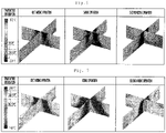
- the first mixing operation is performed for the first set time. Air discharged from the first vane group 81 and 83 may flow toward the sidewalls of the indoor space along the ceiling surface to form horizontal airflow (see FIG. 6 ) and air discharged from the second vane group 82 and 84 may form vertical airflow flowing toward the floor surface of the indoor space (see FIG. 6 ).
- an indoor temperature may be lowered as horizontal airflow flowing on both sidewalls of the room and vertical airflow spreading from the center of the floor surface in a radial direction are mixed.
- the controller 10 may perform control to perform swing operation (S130).
- the swing operation may be defined as operation in which the first vane group 81 and 83 and the second vane group 82 and 84 continuously and reciprocally rotate at an angle between the first rotation angle a and the second rotation angle a' set in the first mixing operation.
- the controller 100 may control the first vane group 81 and 83 to continuously rotate between 30° (maximum angle) which is the first rotation angle a and 70° (minimum angle) which is the second rotation angle a', which are set in the first mixing operation, with elapse of time.
- the controller 100 may control the second vane group 82 and 84 to continuously rotate between 70° which is the second rotation angle a' and 30° which is the first rotation angle a, which are set in the first mixing operation, with elapse of time.
- the temperature of an indoor delay space in which the horizontal airflow or the vertical airflow does not reach or the arrival time of the horizontal airflow or the vertical airflow is delayed may be relatively slowly lowered.
- the controller 100 may determine whether the execution time of the swing operation has exceeded a predetermined second set time (S135).
- the second set time may be set to 5 minutes.
- a dead zone may be formed in a forward-and-backward direction of the indoor space perpendicular to the lateral direction despite the swing operation.
- the temperature of the dead zone may be lowered more slowly than that of the other indoor space.
- the controller 100 may perform control to perform second mixing operation when the second set time has elapsed (S140).
- the first rotation angle a may be set to an angle greater than 60° and less than 80°.
- the first rotation angle a may be set to 70°.
- the first vane group 81 and 83 is positioned at the first rotation angle (70°) to guide air discharged through the outlets 22 downward, thereby forming the vertical airflow.
- the second rotation angle a' may be set to an angle greater than 20° and less than 40°.
- the second rotation angle a' may be set to 30°. Accordingly, the second vane group 82 and 84 is positioned at the second rotation angle (30°) to guide air discharged through the outlets 22 forward and backward, thereby forming the horizontal airflow.
- the controller 100 may control the discharge motor 90 in order to rotate the first vane group 81 and 83 and the second vane group 82 and 84 by newly set rotation angles.
- the second mixing operation S140 may be understood as operation in which the rotation angles of the first vane group 81 and 83 and the second vane group 82 in the first mixing operation are exchanged with each other to eliminate the dead zone.
- the indoor temperature of the dead zone which is not covered by the first mixing operation and the swing operation may be rapidly lowered through the second mixing operation.
- the controller 100 may determine whether the execution time of the second mixing operation has exceeded a predetermined third set time (S145).
- the third set time may be set to 5 minutes.
- Air discharged from the first vane group 81 and 83 may form vertical airflow flowing toward the floor surface of the indoor space (see FIG. 6 ) and air discharged from the second vane group 82 and 84 may flow toward the walls located in the forward-and-backward direction of the indoor space along the ceiling surface to form horizontal airflow (see FIG. 6 ).
- the forward-and-backward direction may be understood as a direction perpendicular to the sidewall direction of the first mixing operation.
- the indoor temperature of the indoor space may be rapidly lowered.
- first mixing operation S120 and the second mixing operation S140 may be understood as operation in which the first vane group 81 and 83 and the second vane group 82 and 84 are positioned at different rotation angles to generate the horizontal airflow or the vertical airflow.
- the controller 100 may perform control to perform return operation (S150).
- the return operation may be defined as operation of performing the swing operation and the first mixing operation in the reverse order.
- the controller 100 may perform control such that the swing operation is performed for the second set time. Accordingly, the first vane group 81 and 83 and the second vane group 82 and 84 may continuously rotate between 30° and 70°.
- the controller 100 may perform control such that the first mixing operation is performed. Accordingly, the first vane group 81 and 83 may rotate at 30° and the second vane group 82 and 84 at 70° to guide air discharged through the outlet 22 for the first set time.
- the dynamic airflow mode may be finished.
- the air conditioner 10 may perform the first mixing operation, the swing operation, the second mixing operation, the swing operation and the first mixing operation in this order, thereby generating dynamic airflow. Therefore, since the temperature of the indoor space where the air conditioner 10 is installed can be lowered without the dead zone, it is possible to reduce the time required to reach the set temperature.
- the air conditioner 10 may perform the first mixing operation S120, the second mixing operation S140 and the return operation S150 similarly to the cooling operation.
- the swing operation in the control method of generating the dynamic airflow during the cooling operation may be excluded in the control method of generating the dynamic airflow during the heating operation.
- the environmental conditions when heating is necessary in the indoor space are different from the environmental conditions when cooling is necessary.
- the swing operation when the swing operation is performed in a room requiring heating, relatively warm air rises and the temperature of a space where the user is located is relatively lowered. That is, a time required for the temperature of a user activity area to reach the set temperature may be increased. Accordingly, in the control method of generating the dynamic airflow during the heating operation, the swing operation may be replaced with the fixing operation.
- the air conditioner 10 for generating the dynamic airflow during the heating operation may perform the fixing operation (S160) when a first set time has elapsed (S125) after the first mixing operation S120.
- the fixing operation S160 may be defined as operation of enabling the first vane group 81 and 83 and the second vane group 82 and 84 having the same rotation angle and guiding air discharged through the outlets 22.
- the first rotation angle a and the second rotation angle a' may be set to an angle greater than 60° and less than 80°.
- the first rotation angle a and the second rotation angle a' may be set to 70°.
- first vane group 81 and 83 and the second vane group 82 and 84 may rotate at the set rotation angle (70°) to guide air discharged through the outlets 22 downward.
- the controller 100 may determine whether the execution time of the fixing operation has elapsed a predetermined second set time (S135).
- the second set time may be set to 5 minutes.
- FIG. 6 is an experimental graph showing airflow discharged when cooling operation of FIG. 5 is performed
- FIG. 7 is an experimental graph showing airflow discharged when heating operation of FIG. 5 is performed
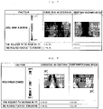
- FIG. 8 is a table showing an experimental result of comparing a conventional ceiling type air conditioner with a ceiling type air conditioner according to the embodiment of the present invention in terms of a time required to reach a set temperature in cooling operation
- FIG. 9 is a table showing an experimental result of comparing a conventional ceiling type air conditioner with a ceiling type air conditioner according to the embodiment of the present invention in terms of a time required to reach a set temperature in heating operation.
- the horizontal airflow flowing along both sidewalls of the indoor space and the vertical airflow descending toward the center of the floor surface of the indoor space and spreading in a radial direction may be mixed.
- the first vane group 81 and 83 and the second vane group 82 and 84 reciprocally rotate at an angle between the first rotation angle a and the second rotation angle a' set in the first mixing operation.
- airflow may be initially concentrated to the center of the indoor space and thus airflow may be rapidly mixed in the indoor space.
- the first rotation angle a and the second rotation angle a' of the first vane 81 and 83 and the second vane group 82 and 84 which are set in the first mixing operation, may be exchanged with each other and newly set. That is, the first vane group 81 and 83 is positioned at the second rotation angle of the first mixing operation and the second vane group 82 and 84 is positioned at the first rotation angle of the first mixing operation.
- air discharged from the first vane group 81 and 83 forms vertical airflow flowing to the floor surface of the indoor space and air discharged from the second vane group 82 and 84 forms horizontal airflow flowing toward to the walls located in the forward-and-backward direction of the indoor space along the ceiling surface.
- a dead zone may be formed between walls located in the upward-and-downward direction of the indoor space and the central axis.
- the dead zone may be understood as a zone where the arrival time of airflow mixed by the first mixing operation and the swing operation is delayed or the mixed airflow is not reached.
- the air conditioner 10 may further facilitate mixing of the horizontal airflow and the vertical airflow in the indoor space by the first mixing operation, the swing operation and the second mixing operation and further increase a mixing range, such that the indoor temperature is rapidly lowered. That is, the air conditioner 10 may enable the indoor temperature to rapidly reach the target set temperature.
- an initial indoor temperature is 33°C
- the set temperature of the air conditioner is set to 26°C with the same air volume (strong wind)
- the dynamic airflow mode during the heating operation is similar to the dynamic airflow mode during the above-described cooling operation ( FIG. 6 ) in terms of the flow of the horizontal airflow and the vertical airflow discharged in the first mixing operation and the second mixing operation.
- the temperature of air discharged from the discharge vane 80 is higher than the initial indoor temperature in the heating operation.
- the fixing operation S160 is performed instead of the swing operation.
- the first vane group 81 and 83 and the second vane group 82 and 84 are positioned at the same rotation angle.
- the first rotation angle a and the second rotation angle a' may be set to 70°.
- warm air discharged downward according to guide of the discharge vane 80 is continuously discharged for a second set time, such that the indoor temperature is relatively rapidly increased from the lower central portion of the indoor space.
- the indoor temperature of a space where the user may feel a pleasant feeling for example, a space from the floor surface of the indoor space to a height of 1.7 m
- the indoor temperature of a space where the user may feel a pleasant feeling for example, a space from the floor surface of the indoor space to a height of 1.7 m
- an initial indoor temperature is 12°C
- the set temperature of the air conditioner is set to 26°C with the same air volume (strong wind)
- the vertical temperature distribution of the indoor space may be more uniform than the heating operation of the conventional air conditioner.
- a temperature difference between the floor surface and the ceiling surface is minimized, thereby minimizing draft.
Applications Claiming Priority (1)
| Application Number | Priority Date | Filing Date | Title |
|---|---|---|---|
| KR1020180055566A KR102168705B1 (ko) | 2018-05-15 | 2018-05-15 | 천장형 공기조화기의 제어방법 |
Publications (2)
| Publication Number | Publication Date |
|---|---|
| EP3569939A1 EP3569939A1 (en) | 2019-11-20 |
| EP3569939B1 true EP3569939B1 (en) | 2022-07-06 |
Family
ID=66379845
Family Applications (1)
| Application Number | Title | Priority Date | Filing Date |
|---|---|---|---|
| EP19172377.4A Active EP3569939B1 (en) | 2018-05-15 | 2019-05-02 | Method for controlling a ceiling type air conditioner |
Country Status (4)
| Country | Link |
|---|---|
| US (2) | US11221159B2 (ko) |
| EP (1) | EP3569939B1 (ko) |
| KR (1) | KR102168705B1 (ko) |
| WO (1) | WO2019221430A1 (ko) |
Families Citing this family (10)
| Publication number | Priority date | Publication date | Assignee | Title |
|---|---|---|---|---|
| CN111023285B (zh) * | 2019-12-05 | 2021-10-15 | 宁波奥克斯电气股份有限公司 | 一种具有双向导风功能的空调及其控制方法 |
| CN111023519A (zh) * | 2019-12-31 | 2020-04-17 | 广州华凌制冷设备有限公司 | 运行方法、装置、空调器和计算机可读存储介质 |
| CN111623414B (zh) * | 2020-04-29 | 2021-09-28 | 海信(山东)空调有限公司 | 一种双出风口的空调器 |
| CN111623415B (zh) * | 2020-04-29 | 2022-02-25 | 海信(山东)空调有限公司 | 一种空调器 |
| CN111780323A (zh) * | 2020-06-12 | 2020-10-16 | 珠海格力电器股份有限公司 | 一种室内空调器的送风控制方法及室内空调器 |
| US20230243540A1 (en) * | 2020-09-08 | 2023-08-03 | Mitsubishi Electric Corporation | Air-conditioning system |
| CN112503740A (zh) * | 2020-11-30 | 2021-03-16 | 珠海格力电器股份有限公司 | 一种空调控制方法、设备及装置、存储介质和空调 |
| CN113154652B (zh) * | 2021-04-02 | 2022-09-06 | 青岛海尔空调器有限总公司 | 空调器及其上下出风的控制方法、计算机可读存储介质 |
| CN113531651A (zh) * | 2021-06-08 | 2021-10-22 | 青岛海信日立空调系统有限公司 | 一种空调器和导风板的控制方法 |
| CN114251818B (zh) * | 2021-12-16 | 2023-06-20 | 宁波奥克斯电气股份有限公司 | 智能送风的控制方法、控制装置及空调器 |
Family Cites Families (14)
| Publication number | Priority date | Publication date | Assignee | Title |
|---|---|---|---|---|
| JPS58146750A (ja) | 1982-02-22 | 1983-09-01 | Nissan Motor Co Ltd | 自動変速機の変速制御装置 |
| KR100408065B1 (ko) | 2001-07-16 | 2003-12-03 | 엘지전자 주식회사 | 천정형 에어컨의 베인 제어방법 |
| KR100408066B1 (ko) * | 2001-07-30 | 2003-12-03 | 엘지전자 주식회사 | 천정형 에어컨의 베인 제어방법 |
| KR100452350B1 (ko) | 2001-12-13 | 2004-10-12 | 주식회사 엘지이아이 | 천장형 공기조화기 및 그 제어방법 |
| KR20070060502A (ko) * | 2005-12-08 | 2007-06-13 | 삼성전자주식회사 | 공기조화기 |
| KR101271060B1 (ko) * | 2005-12-21 | 2013-06-04 | 삼성전자주식회사 | 천장형 공기조화기 |
| EP2484986B1 (en) | 2009-09-28 | 2020-08-05 | Daikin Industries, Ltd. | Control device |
| KR101411027B1 (ko) * | 2010-01-26 | 2014-07-01 | 다이킨 고교 가부시키가이샤 | 공기 조화 장치의 천장 설치형 실내 유닛 |
| KR20120018519A (ko) * | 2010-08-23 | 2012-03-05 | 엘지전자 주식회사 | 공기 조화기의 실내기 및 그 제어방법 |
| JP5250011B2 (ja) | 2010-10-26 | 2013-07-31 | 三菱電機株式会社 | 空気調和機 |
| KR101936635B1 (ko) | 2012-02-14 | 2019-04-03 | 엘지전자 주식회사 | 공기조화기용 실내기 |
| JP6213539B2 (ja) | 2015-09-29 | 2017-10-18 | ダイキン工業株式会社 | 空気調和装置の室内ユニット |
| KR101823208B1 (ko) * | 2015-12-04 | 2018-01-29 | 엘지전자 주식회사 | 공기 조화기 및 그 제어방법 |
| WO2017192610A1 (en) * | 2016-05-02 | 2017-11-09 | Lutron Electronics Co., Inc. | Fan speed control device |
-
2018
- 2018-05-15 KR KR1020180055566A patent/KR102168705B1/ko active IP Right Grant
-
2019
- 2019-04-23 US US16/391,847 patent/US11221159B2/en active Active
- 2019-05-02 EP EP19172377.4A patent/EP3569939B1/en active Active
- 2019-05-03 WO PCT/KR2019/005335 patent/WO2019221430A1/en active Application Filing
-
2021
- 2021-11-03 US US17/518,379 patent/US20220120465A1/en active Pending
Also Published As
| Publication number | Publication date |
|---|---|
| US20220120465A1 (en) | 2022-04-21 |
| US20190353386A1 (en) | 2019-11-21 |
| KR102168705B1 (ko) | 2020-10-22 |
| US11221159B2 (en) | 2022-01-11 |
| WO2019221430A1 (en) | 2019-11-21 |
| EP3569939A1 (en) | 2019-11-20 |
| KR20190130877A (ko) | 2019-11-25 |
Similar Documents
| Publication | Publication Date | Title |
|---|---|---|
| EP3569939B1 (en) | Method for controlling a ceiling type air conditioner | |
| EP3569940B1 (en) | A method of controlling a ceiling type air conditioner | |
| JP6222211B2 (ja) | 空気調和装置 | |
| US11280516B2 (en) | Ceiling type air conditioner and controlling method thereof | |
| EP3358265B1 (en) | Indoor unit of air conditioner | |
| US10488071B2 (en) | Packaged terminal air conditioner unit with vent door position detection | |
| EP2918929B1 (en) | Air-conditioning indoor unit | |
| US10830484B2 (en) | Air-conditioning apparatus | |
| US20120171948A1 (en) | Air flow direction changing device for air conditioning device | |
| CN113932301A (zh) | 具有新风装置的空调室内机及其控制方法 | |
| CN110848807A (zh) | 空调器及其控制方法与装置 | |
| JP3105119U (ja) | 天井型空気調和機 | |
| JP7321283B2 (ja) | 制御装置、空気調和装置および空気調和システム | |
| JP2014031907A (ja) | 空気調和機 | |
| KR102364624B1 (ko) | 공기조화기의 제어방법 | |
| KR100791926B1 (ko) | 공기조화기의 운전제어방법 | |
| JP7415023B2 (ja) | 空調システム | |
| WO2017056365A1 (ja) | 空気調和装置の室内ユニット | |
| CN115077046A (zh) | 空调器及其控制方法 |
Legal Events
| Date | Code | Title | Description |
|---|---|---|---|
| PUAI | Public reference made under article 153(3) epc to a published international application that has entered the european phase |
Free format text: ORIGINAL CODE: 0009012 |
|
| STAA | Information on the status of an ep patent application or granted ep patent |
Free format text: STATUS: REQUEST FOR EXAMINATION WAS MADE |
|
| 17P | Request for examination filed |
Effective date: 20190602 |
|
| AK | Designated contracting states |
Kind code of ref document: A1 Designated state(s): AL AT BE BG CH CY CZ DE DK EE ES FI FR GB GR HR HU IE IS IT LI LT LU LV MC MK MT NL NO PL PT RO RS SE SI SK SM TR |
|
| AX | Request for extension of the european patent |
Extension state: BA ME |
|
| RBV | Designated contracting states (corrected) |
Designated state(s): AL AT BE BG CH CY CZ DE DK EE ES FI FR GB GR HR HU IE IS IT LI LT LU LV MC MK MT NL NO PL PT RO RS SE SI SK SM TR |
|
| GRAP | Despatch of communication of intention to grant a patent |
Free format text: ORIGINAL CODE: EPIDOSNIGR1 |
|
| STAA | Information on the status of an ep patent application or granted ep patent |
Free format text: STATUS: GRANT OF PATENT IS INTENDED |
|
| INTG | Intention to grant announced |
Effective date: 20211206 |
|
| GRAS | Grant fee paid |
Free format text: ORIGINAL CODE: EPIDOSNIGR3 |
|
| GRAA | (expected) grant |
Free format text: ORIGINAL CODE: 0009210 |
|
| STAA | Information on the status of an ep patent application or granted ep patent |
Free format text: STATUS: THE PATENT HAS BEEN GRANTED |
|
| AK | Designated contracting states |
Kind code of ref document: B1 Designated state(s): AL AT BE BG CH CY CZ DE DK EE ES FI FR GB GR HR HU IE IS IT LI LT LU LV MC MK MT NL NO PL PT RO RS SE SI SK SM TR |
|
| REG | Reference to a national code |
Ref country code: AT Ref legal event code: REF Ref document number: 1503110 Country of ref document: AT Kind code of ref document: T Effective date: 20220715 Ref country code: CH Ref legal event code: EP |
|
| REG | Reference to a national code |
Ref country code: DE Ref legal event code: R096 Ref document number: 602019016593 Country of ref document: DE |
|
| REG | Reference to a national code |
Ref country code: IE Ref legal event code: FG4D |
|
| REG | Reference to a national code |
Ref country code: LT Ref legal event code: MG9D |
|
| REG | Reference to a national code |
Ref country code: NL Ref legal event code: MP Effective date: 20220706 |
|
| PG25 | Lapsed in a contracting state [announced via postgrant information from national office to epo] |
Ref country code: SE Free format text: LAPSE BECAUSE OF FAILURE TO SUBMIT A TRANSLATION OF THE DESCRIPTION OR TO PAY THE FEE WITHIN THE PRESCRIBED TIME-LIMIT Effective date: 20220706 Ref country code: RS Free format text: LAPSE BECAUSE OF FAILURE TO SUBMIT A TRANSLATION OF THE DESCRIPTION OR TO PAY THE FEE WITHIN THE PRESCRIBED TIME-LIMIT Effective date: 20220706 Ref country code: PT Free format text: LAPSE BECAUSE OF FAILURE TO SUBMIT A TRANSLATION OF THE DESCRIPTION OR TO PAY THE FEE WITHIN THE PRESCRIBED TIME-LIMIT Effective date: 20221107 Ref country code: NO Free format text: LAPSE BECAUSE OF FAILURE TO SUBMIT A TRANSLATION OF THE DESCRIPTION OR TO PAY THE FEE WITHIN THE PRESCRIBED TIME-LIMIT Effective date: 20221006 Ref country code: NL Free format text: LAPSE BECAUSE OF FAILURE TO SUBMIT A TRANSLATION OF THE DESCRIPTION OR TO PAY THE FEE WITHIN THE PRESCRIBED TIME-LIMIT Effective date: 20220706 Ref country code: LV Free format text: LAPSE BECAUSE OF FAILURE TO SUBMIT A TRANSLATION OF THE DESCRIPTION OR TO PAY THE FEE WITHIN THE PRESCRIBED TIME-LIMIT Effective date: 20220706 Ref country code: LT Free format text: LAPSE BECAUSE OF FAILURE TO SUBMIT A TRANSLATION OF THE DESCRIPTION OR TO PAY THE FEE WITHIN THE PRESCRIBED TIME-LIMIT Effective date: 20220706 Ref country code: FI Free format text: LAPSE BECAUSE OF FAILURE TO SUBMIT A TRANSLATION OF THE DESCRIPTION OR TO PAY THE FEE WITHIN THE PRESCRIBED TIME-LIMIT Effective date: 20220706 Ref country code: ES Free format text: LAPSE BECAUSE OF FAILURE TO SUBMIT A TRANSLATION OF THE DESCRIPTION OR TO PAY THE FEE WITHIN THE PRESCRIBED TIME-LIMIT Effective date: 20220706 |
|
| REG | Reference to a national code |
Ref country code: AT Ref legal event code: MK05 Ref document number: 1503110 Country of ref document: AT Kind code of ref document: T Effective date: 20220706 |
|
| PG25 | Lapsed in a contracting state [announced via postgrant information from national office to epo] |
Ref country code: PL Free format text: LAPSE BECAUSE OF FAILURE TO SUBMIT A TRANSLATION OF THE DESCRIPTION OR TO PAY THE FEE WITHIN THE PRESCRIBED TIME-LIMIT Effective date: 20220706 Ref country code: IS Free format text: LAPSE BECAUSE OF FAILURE TO SUBMIT A TRANSLATION OF THE DESCRIPTION OR TO PAY THE FEE WITHIN THE PRESCRIBED TIME-LIMIT Effective date: 20221106 Ref country code: HR Free format text: LAPSE BECAUSE OF FAILURE TO SUBMIT A TRANSLATION OF THE DESCRIPTION OR TO PAY THE FEE WITHIN THE PRESCRIBED TIME-LIMIT Effective date: 20220706 Ref country code: GR Free format text: LAPSE BECAUSE OF FAILURE TO SUBMIT A TRANSLATION OF THE DESCRIPTION OR TO PAY THE FEE WITHIN THE PRESCRIBED TIME-LIMIT Effective date: 20221007 |
|
| REG | Reference to a national code |
Ref country code: DE Ref legal event code: R097 Ref document number: 602019016593 Country of ref document: DE |
|
| PG25 | Lapsed in a contracting state [announced via postgrant information from national office to epo] |
Ref country code: SM Free format text: LAPSE BECAUSE OF FAILURE TO SUBMIT A TRANSLATION OF THE DESCRIPTION OR TO PAY THE FEE WITHIN THE PRESCRIBED TIME-LIMIT Effective date: 20220706 Ref country code: RO Free format text: LAPSE BECAUSE OF FAILURE TO SUBMIT A TRANSLATION OF THE DESCRIPTION OR TO PAY THE FEE WITHIN THE PRESCRIBED TIME-LIMIT Effective date: 20220706 Ref country code: DK Free format text: LAPSE BECAUSE OF FAILURE TO SUBMIT A TRANSLATION OF THE DESCRIPTION OR TO PAY THE FEE WITHIN THE PRESCRIBED TIME-LIMIT Effective date: 20220706 Ref country code: CZ Free format text: LAPSE BECAUSE OF FAILURE TO SUBMIT A TRANSLATION OF THE DESCRIPTION OR TO PAY THE FEE WITHIN THE PRESCRIBED TIME-LIMIT Effective date: 20220706 Ref country code: AT Free format text: LAPSE BECAUSE OF FAILURE TO SUBMIT A TRANSLATION OF THE DESCRIPTION OR TO PAY THE FEE WITHIN THE PRESCRIBED TIME-LIMIT Effective date: 20220706 |
|
| PLBE | No opposition filed within time limit |
Free format text: ORIGINAL CODE: 0009261 |
|
| STAA | Information on the status of an ep patent application or granted ep patent |
Free format text: STATUS: NO OPPOSITION FILED WITHIN TIME LIMIT |
|
| PG25 | Lapsed in a contracting state [announced via postgrant information from national office to epo] |
Ref country code: SK Free format text: LAPSE BECAUSE OF FAILURE TO SUBMIT A TRANSLATION OF THE DESCRIPTION OR TO PAY THE FEE WITHIN THE PRESCRIBED TIME-LIMIT Effective date: 20220706 Ref country code: EE Free format text: LAPSE BECAUSE OF FAILURE TO SUBMIT A TRANSLATION OF THE DESCRIPTION OR TO PAY THE FEE WITHIN THE PRESCRIBED TIME-LIMIT Effective date: 20220706 |
|
| 26N | No opposition filed |
Effective date: 20230411 |
|
| PG25 | Lapsed in a contracting state [announced via postgrant information from national office to epo] |
Ref country code: AL Free format text: LAPSE BECAUSE OF FAILURE TO SUBMIT A TRANSLATION OF THE DESCRIPTION OR TO PAY THE FEE WITHIN THE PRESCRIBED TIME-LIMIT Effective date: 20220706 |
|
| PGFP | Annual fee paid to national office [announced via postgrant information from national office to epo] |
Ref country code: IT Payment date: 20230406 Year of fee payment: 5 |
|
| PG25 | Lapsed in a contracting state [announced via postgrant information from national office to epo] |
Ref country code: SI Free format text: LAPSE BECAUSE OF FAILURE TO SUBMIT A TRANSLATION OF THE DESCRIPTION OR TO PAY THE FEE WITHIN THE PRESCRIBED TIME-LIMIT Effective date: 20220706 |
|
| REG | Reference to a national code |
Ref country code: DE Ref legal event code: R119 Ref document number: 602019016593 Country of ref document: DE |
|
| REG | Reference to a national code |
Ref country code: CH Ref legal event code: PL |
|
| PG25 | Lapsed in a contracting state [announced via postgrant information from national office to epo] |
Ref country code: MC Free format text: LAPSE BECAUSE OF FAILURE TO SUBMIT A TRANSLATION OF THE DESCRIPTION OR TO PAY THE FEE WITHIN THE PRESCRIBED TIME-LIMIT Effective date: 20220706 |
|
| GBPC | Gb: european patent ceased through non-payment of renewal fee |
Effective date: 20230502 |
|
| REG | Reference to a national code |
Ref country code: BE Ref legal event code: MM Effective date: 20230531 |
|
| PG25 | Lapsed in a contracting state [announced via postgrant information from national office to epo] |
Ref country code: MC Free format text: LAPSE BECAUSE OF FAILURE TO SUBMIT A TRANSLATION OF THE DESCRIPTION OR TO PAY THE FEE WITHIN THE PRESCRIBED TIME-LIMIT Effective date: 20220706 Ref country code: LU Free format text: LAPSE BECAUSE OF NON-PAYMENT OF DUE FEES Effective date: 20230502 Ref country code: LI Free format text: LAPSE BECAUSE OF NON-PAYMENT OF DUE FEES Effective date: 20230531 Ref country code: CH Free format text: LAPSE BECAUSE OF NON-PAYMENT OF DUE FEES Effective date: 20230531 |
|
| REG | Reference to a national code |
Ref country code: IE Ref legal event code: MM4A |
|
| PG25 | Lapsed in a contracting state [announced via postgrant information from national office to epo] |
Ref country code: IE Free format text: LAPSE BECAUSE OF NON-PAYMENT OF DUE FEES Effective date: 20230502 |
|
| PG25 | Lapsed in a contracting state [announced via postgrant information from national office to epo] |
Ref country code: IE Free format text: LAPSE BECAUSE OF NON-PAYMENT OF DUE FEES Effective date: 20230502 Ref country code: DE Free format text: LAPSE BECAUSE OF NON-PAYMENT OF DUE FEES Effective date: 20231201 Ref country code: GB Free format text: LAPSE BECAUSE OF NON-PAYMENT OF DUE FEES Effective date: 20230502 |