EP3566088B1 - Predictive focus tracking apparatus and methods - Google Patents
Predictive focus tracking apparatus and methods Download PDFInfo
- Publication number
- EP3566088B1 EP3566088B1 EP17890176.5A EP17890176A EP3566088B1 EP 3566088 B1 EP3566088 B1 EP 3566088B1 EP 17890176 A EP17890176 A EP 17890176A EP 3566088 B1 EP3566088 B1 EP 3566088B1
- Authority
- EP
- European Patent Office
- Prior art keywords
- sample
- stage
- focus
- location
- optical
- Prior art date
- Legal status (The legal status is an assumption and is not a legal conclusion. Google has not performed a legal analysis and makes no representation as to the accuracy of the status listed.)
- Active
Links
Images


Classifications
-
- G—PHYSICS
- G02—OPTICS
- G02B—OPTICAL ELEMENTS, SYSTEMS OR APPARATUS
- G02B21/00—Microscopes
- G02B21/0004—Microscopes specially adapted for specific applications
- G02B21/002—Scanning microscopes
- G02B21/0024—Confocal scanning microscopes (CSOMs) or confocal "macroscopes"; Accessories which are not restricted to use with CSOMs, e.g. sample holders
- G02B21/0052—Optical details of the image generation
- G02B21/006—Optical details of the image generation focusing arrangements; selection of the plane to be imaged
-
- G—PHYSICS
- G02—OPTICS
- G02B—OPTICAL ELEMENTS, SYSTEMS OR APPARATUS
- G02B21/00—Microscopes
- G02B21/0004—Microscopes specially adapted for specific applications
- G02B21/002—Scanning microscopes
-
- G—PHYSICS
- G02—OPTICS
- G02B—OPTICAL ELEMENTS, SYSTEMS OR APPARATUS
- G02B21/00—Microscopes
- G02B21/0004—Microscopes specially adapted for specific applications
- G02B21/002—Scanning microscopes
- G02B21/0024—Confocal scanning microscopes (CSOMs) or confocal "macroscopes"; Accessories which are not restricted to use with CSOMs, e.g. sample holders
- G02B21/0052—Optical details of the image generation
- G02B21/0076—Optical details of the image generation arrangements using fluorescence or luminescence
-
- G—PHYSICS
- G02—OPTICS
- G02B—OPTICAL ELEMENTS, SYSTEMS OR APPARATUS
- G02B21/00—Microscopes
- G02B21/24—Base structure
- G02B21/241—Devices for focusing
- G02B21/245—Devices for focusing using auxiliary sources, detectors
-
- G—PHYSICS
- G02—OPTICS
- G02B—OPTICAL ELEMENTS, SYSTEMS OR APPARATUS
- G02B27/00—Optical systems or apparatus not provided for by any of the groups G02B1/00 - G02B26/00, G02B30/00
- G02B27/10—Beam splitting or combining systems
- G02B27/16—Beam splitting or combining systems used as aids for focusing
-
- G—PHYSICS
- G02—OPTICS
- G02B—OPTICAL ELEMENTS, SYSTEMS OR APPARATUS
- G02B7/00—Mountings, adjusting means, or light-tight connections, for optical elements
- G02B7/02—Mountings, adjusting means, or light-tight connections, for optical elements for lenses
- G02B7/04—Mountings, adjusting means, or light-tight connections, for optical elements for lenses with mechanism for focusing or varying magnification
- G02B7/09—Mountings, adjusting means, or light-tight connections, for optical elements for lenses with mechanism for focusing or varying magnification adapted for automatic focusing or varying magnification
-
- G—PHYSICS
- G02—OPTICS
- G02B—OPTICAL ELEMENTS, SYSTEMS OR APPARATUS
- G02B7/00—Mountings, adjusting means, or light-tight connections, for optical elements
- G02B7/02—Mountings, adjusting means, or light-tight connections, for optical elements for lenses
- G02B7/04—Mountings, adjusting means, or light-tight connections, for optical elements for lenses with mechanism for focusing or varying magnification
- G02B7/10—Mountings, adjusting means, or light-tight connections, for optical elements for lenses with mechanism for focusing or varying magnification by relative axial movement of several lenses, e.g. of varifocal objective lens
- G02B7/102—Mountings, adjusting means, or light-tight connections, for optical elements for lenses with mechanism for focusing or varying magnification by relative axial movement of several lenses, e.g. of varifocal objective lens controlled by a microcomputer
Definitions
- JP 2003 295065 A relates to a microscope using a line sensor.
- US 2015/130920 A1 describes a further line scanning system that uses a single illumination light source.
- US 2009/195688A1 refers to an imaging device having an objective and a stage as well as a method for autofocusing.
- JP 2016 024042 A relates to another system having a stage and an objective and a focus control method.
- GB 2 537 786 A refers to a microspectroscopy device provided with an objective lens.
- the system is often calibrated for the focal plane prior to system use.
- this calibration may be inadequate to account for variations across the area of the sample or samples.
- a sample container having a plurality of samples at various sample locations defined by a set of coordinates. These sample locations can be in different focal planes due to bending or warping, or due to thermal changes or other factors causing irregularities across the sample container.
- some systems perform real-time focusing as the scanning operation is performed at various sample locations along the sample container.
- there is latency associated with refocusing the system at each sample location This latency affects the speed with which various samples within the sample container can be imaged.
- the invention provides for an imaging system according to claim 1 and a method of focus tracking according to claim 6.
- Other features and aspects will become apparent from the dependent claims and the following description.
- Provided in examples herein are biological analysis instruments. More particularly, various examples describe focus tracking systems and methods for instruments used in analyzing biological samples.
- Various examples of the technologies disclosed herein provide systems and methods for reducing latency associated with focus tracking in optical scanners.
- systems and methods are provided to derive focus tracking error signal information for sample locations in advance of reaching those sample locations. This is accomplished by adding additional points to the optical system field of view that can be used to look ahead to obtain focusing information for one or more sample locations in a direction or directions of future sample locations to be examined.
- a history file can be generated and maintained for a sample container that includes focusing information for the plurality of sample locations across that sample container. When the sample container is loaded for imaging operations, its associated history file can also be installed to provide focusing information at each of the identified sample locations.
- improved actuators can be used to increase the speed with which focusing is accomplished.
- Some examples relate to an imaging system according to claim 1.
- Various examples of the technologies disclosed herein provide systems and methods for reducing latency associated with focus tracking in optical scanners.
- systems and methods are provided to derive focus tracking error signal information for sample locations in advance of reaching those sample locations. This is accomplished by adding additional points to the optical system field of view that can be used to look ahead to obtain focusing information for one or more sample locations in a direction or directions of future sample locations to be examined.
- a history file can be generated and maintained for a sample container that includes focusing information for the plurality of sample locations across that sample container. When the sample container is loaded for imaging operations, its associated history file can also be installed to provide focusing information at each of the identified sample locations.
- improved actuators can be used to increase the speed with which focusing is accomplished.
- Various examples of the systems and methods disclosed herein can provide a predictive focus tracking system and improved focus actuators that allow increased scan speeds and improved focus control as compared to conventional solutions.
- the system may be implemented to allow uniform, diffraction limited imaging at high scan speeds, leading to high data acquisition rates.
- some implementations may allow a 4x scan speed, resulting in the scanning of data on the order of 120Gb/hour.
- Predictive focus techniques and improved actuator technologies such as those described herein can be used to reduce latency and thereby help to achieve such increased scanning speeds as well as to achieve nanometer scale focusing precision.
- the example imaging scanning system may include a device for obtaining or producing an image of a region.
- the example outlined in FIG. 1 shows an example imaging configuration of a backlight design.
- subject samples are located on sample container 110, which is positioned on a sample stage 170 under an objective lens 142.
- Light source 160 and associated optics direct a beam of light, such as laser light, to a chosen sample location on the sample container 110.
- the sample fluoresces and the resultant light is collected by the objective lens 142 and directed to a photo detector 140 to detect the florescence.
- Sample stage 170 is moved relative to objective lens 142 to position the next sample location on sample container 110 at the focal point of the objective lens 142. Movement of sample stage 110 relative to objective lens 142 can be achieved by moving the sample stage itself, the objective lens, the entire optical stage, or any combination of the foregoing. Further examples may also include moving the entire imaging system over a stationary sample.
- Fluid delivery module or device 100 directs the flow of reagents (e.g., fluorescent nucleotides, buffers, enzymes, cleavage reagents, etc.) to (and through) sample container 110 and waste valve 120.
- reagents e.g., fluorescent nucleotides, buffers, enzymes, cleavage reagents, etc.
- sample container 110 can be implemented as a flowcell that includes clusters of nucleic acid sequences at a plurality of sample locations on the sample container 110.
- the samples to be sequenced may be attached to the substrate of the flowcell, along with other optional components.
- the system also comprises temperature station actuator 130 and heater/cooler 135 that can optionally regulate the temperature of conditions of the fluids within the sample container 110.
- Camera system 140 can be included to monitor and track the sequencing of sample container 110.
- Camera system 140 can be implemented, for example, as a CCD camera, which can interact with various filters within filter switching assembly 145, objective lens 142, and focusing laser/focusing laser assembly 150.
- Camera system 140 is not limited to a CCD camera and other cameras and image sensor technologies can be used.
- Light source 160 e.g., an excitation laser within an assembly optionally comprising multiple lasers
- other light source can be included to illuminate fluorescent sequencing reactions within the samples via illumination through fiber optic interface 161 (which can optionally comprise one or more re-imaging lenses, a fiber optic mounting, etc).
- Low watt lamp 165, focusing laser 150, and reverse dichroic 185 are also presented in the example shown.
- focusing laser 150 may be turned off during imaging.
- an alternative focus configuration can include a second focusing camera (not shown), which can be a quadrant detector, a Position Sensitive Detector (PSD), or similar detector to measure the location of the scattered beam reflected from the surface concurrent with data collection.
- PSD Position Sensitive Detector
- Sample container 110 can be ultimately mounted on a sample stage 170 to provide movement and alignment of the sample container 110 relative to the objective lens 142.
- the sample stage can have one or more actuators to allow it to move in any of three dimensions.
- actuators can be provided to allow the stage to move in the X, Y and Z directions relative to the objective lens. This can allow one or more sample locations on sample container 110 to be positioned in optical alignment with objective lens 142.
- Focus component 175 is shown in this example as being included to control positioning of the optical components relative to the sample container 110 in the focus direction (typically referred to as the z axis, or z direction).
- Focus component 175 can include one or more actuators physically coupled to the optical stage or the sample stage, or both, to move sample container 110 on sample stage 170 relative to the optical components (e.g., the objective lens 142) to provide proper focusing for the imaging operation.
- the actuator may be physically coupled to the respective stage such as, for example, by mechanical, magnetic, fluidic or other attachment or contact directly or indirectly to or with the stage.
- the one or more actuators can be configured to move the stage in the z-direction while maintaining the sample stage in the same plane (e.g., maintaining a level or horizontal attitude, perpendicular to the optical axis).
- the one or more actuators can also be configured to tilt the stage. This can be done, for example, so that sample container 110 can be leveled dynamically to account for any slope in its surfaces.
- Focusing of the system generally refers to aligning the focal plane of the objective lens with the sample to be imaged at the chosen sample location. However, focusing can also refer to adjustments to the system to obtain a desired characteristic for a representation of the sample such as, for example, a desired level of sharpness or contrast for an image of a test sample. Because the usable depth of field of the focal plane of the objective lens is typically very small (sometimes on the order of 1 ⁇ m or less), focus component 175 closely follows the surface being imaged. Because the sample container is not perfectly flat as fixtured in the instrument, focus component 175 may be set up to follow this profile while moving along in the scanning direction (typically referred to as the y-axis).
- the light emanating from a test sample at a sample location being imaged can be directed to one or more detectors 140.
- Detectors can include, for example a CCD camera.
- An aperture can be included and positioned to allow only light emanating from the focus area to pass to the detector.
- the aperture can be included to improve image quality by filtering out components of the light that emanate from areas that are outside of the focus area.
- Emission filters can be included in filter switching assembly 145, which can be selected to record a determined emission wavelength and to cut out any stray laser light.
- sample container 110 can include one or more substrates upon which the samples are provided.
- sample container 110 can include one or more substrates on which nucleic acids to be sequenced are bound, attached or associated.
- the substrate can include any inert substrate or matrix to which nucleic acids can be attached, such as for example glass surfaces, plastic surfaces, latex, dextran, polystyrene surfaces, polypropylene surfaces, polyacrylamide gels, gold surfaces, and silicon wafers.
- the substrate is within a channel or other area at a plurality of locations formed in a matrix or array across the sample container 110.
- a controller can be provided to control the operation of the scanning system.
- the controller can be implemented to control aspects of system operation such as, for example, focusing, stage movement, and imaging operations.
- the controller can be implemented using hardware, software, or a combination of the foregoing.
- the controller can include one or more CPUs or processors with associated memory.
- the controller can comprise hardware or other circuitry to control the operation.
- this circuitry can include one or more of the following: field programmable gate array (FPGA), application specific integrated circuit (ASIC), programmable logic device (PLD), complex programmable logic device (CPLD), a programmable logic array (PLA), programmable array logic (PAL) or other similar processing device or circuitry.
- the controller can comprise a combination of this circuitry with one or more processors.
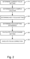
- FIG. 2 is a diagram illustrating a process for predictive focus tracking in accordance with one example of the systems and methods disclosed herein.
- the system determines a current focus setting.
- the system can be configured to determine the focus setting for a current imaging operation at a current sample location on a sample container.
- this focus setting for the current sample location can be determined in advance (e.g. using the predictive methods described herein).
- a focus beam pair generated by a focusing laser is reflected off of the sample location to measure the required focus, and the sample stage is moved relative to the optical stage to focus the optical stage onto a current sample location.
- the movement of the sample stage relative to the optical stage for focusing is generally described as movement along the z-axis or in the z direction.
- the terms "z-axis" and "z direction" are intended to be used consistently with their use in the art of microscopy and imaging systems in general, in which the z-axis refers to the focal axis. Accordingly, a z-axis translation results in increasing or decreasing the length of the focal axis.
- a z-axis translation can be carried out, for example, by moving a sample stage relative to an optical stage (e.g., by moving the sample stage or an optical element or both).
- z-axis translation can be carried out by driving an objective lens, the optical stage, or the sample stage, or a combination of the foregoing, any of which can be driven by actuating one or more servos or motors or other actuators that are in functional communication with the objective lens or the sample stage or both.
- the actuators can be configured to tilt the sample stage relative to the optical stage to, for example, effectively level the sample container on a plane perpendicular to the optical imaging axis. Where this dynamic tilting is performed to effectively level the sample locations on the sample container, this can allow the sample container to be moved in the x and y directions for scanning with little or no movement in the z-axis required.
- the system determines the next sample location to which the optical stage will be positioned for imaging. This can be determined, for example, by the scanning algorithm that is used to move the sample stage relative to the optical stage (e.g., in the x and y directions). For example, in some applications the system moves from one sample location to the next adjacent sample location until all desired sample locations are imaged. In other applications, other scanning patterns may be implemented.
- the system determines the focus setting for this next sample location. This is illustrated at operation 220.
- the focus setting for this next sample location is determined in advance of the objective lens being positioned for imaging operations at the next sample location. Accordingly, in some examples the focus setting for the next sample location can be determined, for example, while the system is imaging the current sample location or before the system is positioned to image the current sample location.
- the focus setting for the next sample location is determined by using a pair of off-axis look-ahead focus beams that are directed to the next location to determine the next location in advance.
- one or more beams can be directed to a future sample location, to previous sample locations (e.g., in the reverse scanning direction), to sample locations to the side of the current sample location (side relative to the scan travel direction, whether perpendicular to the direction of travel or at other angles) to gather focus information for various points in addition to the focus setting for the next immediate sample location.
- focus settings for a plurality of sample locations on a sample carrier may be determined in advance of the current scanning operation. These focus settings for each of the plurality of sample locations can be stored electronically in a history file for a given sample container and recalled when the sample container is reloaded into the imaging system for scanning operations. Predetermination of the sample-location focus settings for a sample carrier can be done in a set-up run, which may be run, for example, without any samples in place. Alternatively, the predetermination can be made during an operational scanning run of samples in the sample carrier and stored in the history file for future scanning operations. In various examples, image quality from previous runs can be checked and used to augment or update a previously stored focus model for the system. Where image quality from previous runs is high, this information can be used to rank the history file, or points on the history file at a relatively high confidence level.
- the system determines the difference between the current focus setting and the next focus setting. This difference indicates the amount of change in the distance between the optical stage and the sample stage that will be required to bring the system into focus for the next sample location.
- the system uses this information at operation 230 to calculate a focus change setting. This difference in the focus setting from the current sample location to the next sample location provides an error signal that is used to determine a control output used to control the focus actuator in the focus component 175.
- the system may be implemented to determine parameters for a drive signal that will be applied to the actuator to move the optical stage relative to the sample stage for the next sampling operation.
- a greater control output e.g., one or more parameters such as larger drive current, larger voltage, and greater duty cycle
- a smaller control output e.g., smaller drive current, lower voltage, and smaller duty cycle
- the control output can be adjusted, for example, by adjusting the current or voltage applied to the actuator.
- the time at which the drive signal is applied to the actuator can be adjusted based on the z-distance translation amount that is required for the change in focusing. For example, where the required distance is greater, the drive signal can be applied earlier. However, in other examples, the drive signal is applied as early as possible after the sampling is complete at the current location regardless of the difference in focus settings. In further examples, the drive signal can be supplied to multiple actuators at different output levels to tilt the sample instead of, or in addition to, moving the entire sample along the z-axis.
- the parameters of the drive signal, and the time at which the drive signal is applied, can be determined based on the actuator type and drive requirements. For example, some actuators present a capacitive load and require that a certain level of charge be built up before the actuator is actuated. An example of such an actuator includes piezoelectric actuators. Other actuators, such as voice coil actuators for example, may present more of an inductive load. Such actuators have different characteristics dictating the requirements of the drive signal parameters.
- the determined drive signal is applied to the actuator to execute the focus correction.
- a drive signal with the determined parameters is provided to the actuator to drive the actuator to move the optical stage relative to the sample stage to bring the system into focus.
- the actual focus adjustment applied to bring the sample into focus can be compared against the predictive focus model to ensure that the model is accurate.
- image quality can be used to gauge the accuracy of the predictive focus model.
- a pair of off-axis laser beams is directed to the sample container (e.g. sample container 110) to determine focus settings for locations of the sample container other than the current sample location being sampled.
- Said focus beams are directed ahead of the current sample location (i.e., in the direction of the scanning) to measure the desired focus setting for one or more locations beyond the current sample location.
- one or more additional beams can be directed in the forward, reverse or side directions to gather focus information for various points in addition to the focus setting for the next immediate sample location.
- These additional off-axis beams can be used to determine focus settings for multiple positions on the sample container (e.g., for other sample locations) and this information can be stored and used for predictive focus determination.
- FIG. 3 is a diagram illustrating an example optical design for predictive focus tracking in accordance with one example of the systems and methods described herein.
- this example system includes a sample container 110, which in this example is a flowcell, and an objective lens 142 that is used to focus light for imaging and for focusing on to the desired locations of the sample container 110.
- a pinhole mask 252 an image sensor 254, a re-imaging lens 256, a differential reducing wedge 258, a differential splitting window 260, and a focus projection lens 262.
- FIG. 4 which comprises FIGs. 4A and 4B illustrates another example optical system for predictive focus tracking as an alternative to that presented in FIG. 3 .
- FIG. 4A illustrates another example optical design for predictive focus tracking.
- FIG. 4B is a diagram illustrating an alternative view of a portion of the optical system shown in FIG. 4A .
- the example shown in FIG. 4A is illustrated with a single beam, which is the center beam in this case.
- this system will operate with more than one beam such as, for example, with 3 beams as in FIG. 3 .
- a three-beam system can provide look-ahead and look-behind focus tracking.
- laser 270 generates light for the focusing beams and is optically coupled into the system.
- Light from laser 270 can be coupled via a fiber for example to a beam splitter prism 272, such as a lateral displacement beam splitter. Filters may be included, if needed, such as for source selection.
- Prism 272 splits the transmit beam into two substantially parallel spots of roughly equal intensity. This is included to provide for differential measurement in the focusing model.
- a diffraction grating 274 generates multiple copies of the input beams.
- a beam splitter cube or multiple laser sources can be used to generate the multiple beams.
- diffraction grating 274 may generate three output beams for each of the two input beams. An example of this for one input beam is shown at FIG. 4B .
- a flat-top, or dove prism, 276 redirects the multiple beams.
- the prism is configured such that the beams converge at the pupil of the objective lens 142 so the beams at the sample container are normal to the sample container.
- FIG. 4B An example of this for a three-output-beam configuration is shown at FIG. 4B .
- the received signal from the sample container returns through the beam splitter 277 and reflects off mirror 279.
- receive prisms 280 and 282 consolidate the spots onto the focal plane of image sensor 284.
- these can be implemented as dove and roof prisms to refract and aim the rays exiting the microscope object to fit on the image sensor array.
- a roof prism can be used to refract the return beams to consolidate the spots within a spot pair onto the focal plane of the image sensor, and a dove prism to refract the fore/aft spot pairs to consolidate all spot pairs onto the focal plane.
- 3 beams pass through each of the two prism halves of the roof prism. However, in the other axis, the beams are diverging, which is why the dove prism is included to correct those.
- various optical components are implemented using prisms. Some or all of these may be implemented using lenses, however prisms may be desirable as these components are generally less sensitive to misalignment as compared to their lens counterparts. Prisms may also be more desirable than lens systems because prisms are generally more compact and include fewer elements.
- Objective lens 142 in the examples of FIGs. 3 and 4 provides a generally circular field of view on the sample container.
- the center of the field of view is the current sample location being imaged.
- the direction of scan within that field of view is typically either the x or the y axis.
- the direction of scan will be assumed to be in the y direction.
- a laser light source (not illustrated) generates the focusing beams.
- three beams are used to provide a three-point differential off-axis predictive focus estimation - one beam for the current sample location and two additional beams for look-ahead and look-behind focus tracking. These two additional beams are used to determine the focus distance along the z axis between the optical stage and sample locations on the sample container.
- one pair of beams is directed toward current the sample location.
- the sample location of the sample currently being imaged is approximately at the center of the field of view of objective lens 142.
- one pair of beams is directed along the y axis ahead of the scanning operation (i.e., in the +y direction) and the other is directed along the y-axis behind the current location (i.e., in the -y direction).
- the two additional beams are directed at locations at a distance that is approximately one-third of the distance from the center to the edge of the field of view ahead of and behind the current sample location.
- a number of additional focusing beams other than two can be provided.
- one or more beams in addition to the center pair of beams and the pair of beams projected on a next sample location, can be directed at one or more of the +x,-x, +y,-y directions as well as in the +x,+y, +x,-y, -x,+y, -x,-y directions.
- Information from these beams can be used to gather for information about multiple locations on the sample container (e.g., sample container 110). This information can be used, for example to gather and store focus settings for sample locations on the sample container at multiple sample locations. Focusing information obtained using these additional focus beams can also be used to compute the slope of the sample container in the region, which indicates the rate of change of the focus distance along the sample container. For example, in the case of a three-beam system, the system uses the known scanning direction to determine which of the additional beams is looking ahead and which is looking behind. Focus information from these two beams and from the center beam provides three points from which the slope of the sample container within this region can be calculated. If additional beams are included and directed to the side, slope can be determined in the x and y directions.
- the system can use the slope to predict focus changes in the forward direction and use this information to determine one or more parameters of the drive signal to be applied to drive the actuator.
- the control output can be proportional to the slope detected in that region. Where the slope is greater, higher levels of current, for example, can be applied to allow the z stage to be more quickly moved into position for the next sample location. Whether the sample locations are locations along a continuous sample, or discrete locations on the sample container, this information about the focusing distance before the system is positioned to scan the next sample location allows the focus operation to be performed in a predictive manner.
- the slope information can further be used to level the sample container relative to the optical stage. This can be done, for example, by tilting the sample stage. With the sample stage level relative to the optical stage, scanning can progress in the x and y directions with little or no further adjustment in the z direction. Because the sample container may not be uniform across its area, this leveling can be done on a continuous or regular basis as scanning progresses to present a relatively level sample surface to the imaging system. In various examples, the leveling can be accomplished by providing three or more actuators, each driven independently to allow the sample stage to be tilted relative to the optical stage.
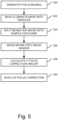
- FIG. 5 is a diagram illustrating an example process for predictive focusing using an optical system such as the optical system shown in FIG. 3 .
- the process illustrated in FIG. 5 is described in the context of FIG. 3 and in the context of the example three-point off-axis configuration, having a center focusing beam, a look-ahead beam and a look-behind beam.
- the laser generates the focusing light that will be used for the predictive focusing operations. In some applications light from the laser is coupled into a fiber and the output of the fiber is collimated.
- pinhole mask 252 is back illuminated (in the case of FIG. 3 ). In the example illustrated in FIG. 3 , three pin holes are provided corresponding to the example three-point off-axis predictive focusing system.
- the three focusing beams are split into six beams.
- focus projection lens 262 projects the three beams onto differential splitting window 260, and differential splitting window 260 splits them into six beams - two for the center beam, and to each for the look-ahead and look-behind beams.
- the focus beam and the additional look-ahead/look-behind/look-aside beams are split into two beams each.
- these three beams would be split into six separate beams.
- the pin holes are imaged onto sample container 110.
- these beams are split by a differential splitting window 260 into two beams each, creating a total of six beams.
- Differential splitting window 260 can be implemented as a diffraction grating to split each focusing beam thereby creating multiple beams for each focusing beam.
- a lateral displacement prism (not illustrated in FIG. 3 ) can be included to cause those beams to converge at the entrance pupil of the objective lens 142.
- Objective lens 142 images these beams onto sample container 110.
- the beams can be imaged as a center beam, a look-ahead beam and a look-behind beam.
- differential reducing wedge 258 and re-imaging lens 256 can be provided to focus and place the spots one to the image sensor.
- the focus correction amount can be calculated from the beams imaged onto the input sensor.
- focus information from points within the field of view of the objective lens can be calculated and used to determine focus correction amounts.
- focus information from the three pairs of beams can be used to calculate a slope of the sample container along the sample locations. The slope can be used to compute one or more drive signal parameters (e.g. the current level, voltage level, duty cycle, on-time, etc.) to drive the actuator to adjust the sample stage relative to the optical stage for the next sample location.
- the focus correction is executed by providing the determined one or more drive signal parameters at the appropriate level to the actuator.
- a controller can be included to control the operations of the predictive focus tracking.
- a processor system having one or more processors executing program code to control the operations of the system can be used.
- a hardware solution to control the operations of the system such as by using one or more of the following: FPGA, ASIC, PLD, CPLD, PLA, PAL, or other like circuitry.
- FIG. 6 is a diagram illustrating an example process for predictive focus tracking using stored information in accordance with one example of the systems and methods described herein.
- a sample container e.g. sample container 110
- focus settings for each of a plurality of sample locations on the sample container are measured.
- the focus amount can be measured at each of these discrete locations.
- focus settings can be measured at each of a plurality of locations across the container, where the quantity of locations and spacing between these locations can be determined based on the resolution desired for the sample scan.
- the focus settings for the sample container are stored. These can be stored electronically in a history file in memory so that they can be recalled for later use during scanning operations. The history file or the information therein can be tagged to be identified as containing the focus information for that particular sample container.
- a sample container is loaded into the scanning system for scanning operations.
- the sample container will include a sample or samples to be imaged.
- the sample container can include an identifier to uniquely identify the sample container.
- sample containers can be identified by class while in other examples, sample containers can be identified individually.
- the sample container identification can be entered into the system by a user, or it can be optically or electronically detected when the sample container is loaded into the system.
- stored focus settings for the identified sample container are retrieved.
- the identification of the sample container can be used to identify the file that contains the stored focus settings for that sample container.
- the stored settings contained in that file can be used to perform predictive focusing operations for the scan being conducted with that sample container. For example, slope information can be computed using the focus settings stored in the history file, and this slope information can be used to determine the parameters of the drive signal applied to the actuator during imaging operations.
- FIG. 7 is a block diagram illustrating an example focus control system for focus tracking in accordance with one example of the systems and methods described herein.
- This example focus control system includes focus tracking circuitry 432 that is configured to determine the current and look ahead focus settings that are used to generate the drive signal that drives the focus tracking feedback loop in the z stage 434.
- commands 452 based on the focus settings difference, are fed to the z-stage 434.
- the Z stage 434 is configured to move the objective lens 446 (e.g., objective lens 142).
- Actuator 444 moves the optical stage, and in particular the objective lens 446, in response to the drive signal provided by the Z-stage amplifier 438.
- actuator 444 can include a piezoelectric actuator, a voice coil actuator, a motor, or other like actuators.
- An encoder 442 provides information about the actuator position and its movement. This encoder information 454 can be fed back through the z-stage controller 436 to focus tracking circuitry 432 and can be used in determining the error signal.
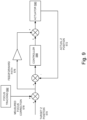
- FIG. 8 is a diagram illustrating an example architecture for a z-stage controller in accordance with one example of the systems and methods described herein.
- This example controller incorporates both feedforward and feedback control to generate the drive signal to control the stage actuator.
- this can be implemented as a proportional, integral and derivative (PID) control for both the error signal and the feedforward control branches of the control system.
- PID proportional, integral and derivative
- the difference between the target focus setting and the actual focus setting are computed and fed to control block 488.
- Position information is also sent via feedforward path 476 and added to the output signal of control block 488.
- This output signal from drive circuitry within the control block 488 provides the control output signal, which is used to drive actuator 490.
- the magnitude of the difference between the target focus position and the current actual position is provided via the feedforward path 476 to adjust the control output signal.
- FIG. 9 is diagram illustrating another example architecture for a z-stage controller in accordance with one example of the systems and methods described herein. This example also incorporates feedback and feedforward control.
- the target focus setting e.g., target z position 570
- the target z position 570 is provided to controller 588, which determines the drive signal needed to command actuator 590 to position the stage.
- Controller 588 may also include drive circuitry to generate the drive signal.
- the drive signal determination is made using the magnitude of the difference between the target focus setting (target z position 570) and the current focus setting (actual z position 572) which can be provided, for example, by actuator 590.
- the drive signal used to drive the actuator is adjusted by the signal from the feedforward control path 576.
- measured focus correction signal 578 is generated by focus tracking circuitry 592.
- the correction information can be determined, for example, using the lookahead predictive focus tracking or predictive focus tracking based on history data as described above, or using other predictive focus tracking techniques.
- the correction information is added to the commanded stage position to adjust the drive signal according to the slope of the change in the focus setting for scanning operations.
- an actuator can be used to position the sample stage relative to the optical stage by repositioning either the sample stage or the optical stage (or parts thereof), or both to achieve the desired focus setting.
- piezoelectric actuators can be used to move the desired stage.
- a voice coil actuator can be used to move the desired stage.
- the use of a voice coil actuator can provide reduced focusing latency as compared to its piezoelectric counterparts.
- coil size may be chosen as a minimum coil size necessary to provide the desired movement such that the inductance in the coil can also be minimized. Limiting coil size, and therefore limiting its inductance, provides quicker reaction times and requires less voltage to drive the actuator.
- focus information from points other than a current sample location can be used to determine the slope or the magnitude of change in the focus setting for scanning operations. This information can be used to determine whether to feed the drive signal to the actuator earlier and how to set the parameters of the drive signal.
- the system can be precalibrated to allow drive thresholds to be determined for the actuator. For example, the system can be configured to supply to the actuator drive signals at different levels of control output to determine the highest amount of control output (e.g., the maximum amount of drive current) the actuator can withstand without going unstable. This can allow the system to determine a maximum control output amount to be applied to the actuator.
- Coupled refers to direct or indirect joining, connecting, fastening, contacting or linking, and may refer to various forms of coupling such as physical, optical, electrical, fluidic, mechanical, chemical, magnetic, electromagnetic, communicative or other coupling, or a combination of the foregoing. Where one form of coupling is specified, this does not imply that other forms of coupling are excluded. For example, one component physically coupled to another component may reference physical attachment of or contact between the two components (directly or indirectly), but does not exclude other forms of coupling between the components such as, for example, a communications link (e.g., an RF or optical link) also communicatively coupling the two components. Likewise, the various terms themselves are not intended to be mutually exclusive. For example, a fluidic coupling, magnetic coupling or a mechanical coupling, among others, may be a form of physical coupling.
Landscapes
- Physics & Mathematics (AREA)
- General Physics & Mathematics (AREA)
- Optics & Photonics (AREA)
- Chemical & Material Sciences (AREA)
- Analytical Chemistry (AREA)
- Engineering & Computer Science (AREA)
- General Engineering & Computer Science (AREA)
- Microscoopes, Condenser (AREA)
- Automatic Focus Adjustment (AREA)
- Health & Medical Sciences (AREA)
- Radar Systems Or Details Thereof (AREA)
- Studio Devices (AREA)
- Lens Barrels (AREA)
- Immunology (AREA)
- Focusing (AREA)
- Computer Vision & Pattern Recognition (AREA)
- Chemical Kinetics & Catalysis (AREA)
- Nuclear Medicine, Radiotherapy & Molecular Imaging (AREA)
- Life Sciences & Earth Sciences (AREA)
- Biochemistry (AREA)
- General Health & Medical Sciences (AREA)
- Pathology (AREA)
- Prostheses (AREA)
Applications Claiming Priority (3)
| Application Number | Priority Date | Filing Date | Title |
|---|---|---|---|
| US201762442947P | 2017-01-05 | 2017-01-05 | |
| GBGB1704770.5A GB201704770D0 (en) | 2017-01-05 | 2017-03-24 | Predictive focus tracking apparatus and methods |
| PCT/IB2017/058383 WO2018127769A1 (en) | 2017-01-05 | 2017-12-22 | Predictive focus tracking apparatus and methods |
Publications (4)
| Publication Number | Publication Date |
|---|---|
| EP3566088A1 EP3566088A1 (en) | 2019-11-13 |
| EP3566088A4 EP3566088A4 (en) | 2020-08-12 |
| EP3566088B1 true EP3566088B1 (en) | 2024-01-31 |
| EP3566088C0 EP3566088C0 (en) | 2024-01-31 |
Family
ID=58687922
Family Applications (1)
| Application Number | Title | Priority Date | Filing Date |
|---|---|---|---|
| EP17890176.5A Active EP3566088B1 (en) | 2017-01-05 | 2017-12-22 | Predictive focus tracking apparatus and methods |
Country Status (17)
| Country | Link |
|---|---|
| US (2) | US11054624B2 (enExample) |
| EP (1) | EP3566088B1 (enExample) |
| JP (1) | JP7050701B2 (enExample) |
| KR (1) | KR102551459B1 (enExample) |
| CN (1) | CN109313329B (enExample) |
| AU (1) | AU2017390821B2 (enExample) |
| BR (1) | BR112018076996B1 (enExample) |
| CA (1) | CA3022894C (enExample) |
| GB (1) | GB201704770D0 (enExample) |
| IL (2) | IL262707B2 (enExample) |
| MX (1) | MX2019007874A (enExample) |
| MY (1) | MY195238A (enExample) |
| RU (1) | RU2710004C1 (enExample) |
| SA (1) | SA518400567B1 (enExample) |
| SG (1) | SG11201811328PA (enExample) |
| TW (1) | TWI772348B (enExample) |
| WO (1) | WO2018127769A1 (enExample) |
Families Citing this family (12)
| Publication number | Priority date | Publication date | Assignee | Title |
|---|---|---|---|---|
| GB201704770D0 (en) * | 2017-01-05 | 2017-05-10 | Illumina Inc | Predictive focus tracking apparatus and methods |
| AU2018353924A1 (en) | 2017-12-29 | 2019-07-18 | Clear Labs, Inc. | Automated priming and library loading device |
| NL2020618B1 (en) * | 2018-01-12 | 2019-07-18 | Illumina Inc | Real time controller switching |
| JP6960352B2 (ja) * | 2018-02-20 | 2021-11-05 | 株式会社日立ハイテク | ステージ装置、及び荷電粒子線装置 |
| US20230088338A1 (en) | 2021-09-10 | 2023-03-23 | Illumina, Inc. | Sequencer focus quality metrics and focus tracking for periodically patterned surfaces |
| WO2023049047A1 (en) | 2021-09-27 | 2023-03-30 | Beckman Coulter, Inc. | Adjustable mounting apparatus |
| TW202336423A (zh) | 2021-10-01 | 2023-09-16 | 美商伊路米納有限公司 | 用於傳輸光之設備及方法 |
| CN115086563B (zh) * | 2022-07-27 | 2022-11-15 | 南方科技大学 | 基于SerialEM的单颗粒数据收集方法和装置 |
| CN115576075B (zh) * | 2022-11-21 | 2023-03-14 | 上海隐冠半导体技术有限公司 | 一种自动对焦系统和方法 |
| CN120457383A (zh) * | 2022-12-09 | 2025-08-08 | 深圳华大智造科技股份有限公司 | 对焦控制方法及相关设备 |
| US12452530B2 (en) | 2023-12-20 | 2025-10-21 | Illumina, Inc. | Intelligent sample tilt adjustment with zones having variable size |
| CN119395852B (zh) * | 2024-12-31 | 2025-05-02 | 江苏慕藤光精密光学仪器有限公司 | 一种激光自动跟焦方法、装置及设备 |
Citations (1)
| Publication number | Priority date | Publication date | Assignee | Title |
|---|---|---|---|---|
| GB2537786A (en) * | 2014-03-05 | 2016-10-26 | Hitachi High Tech Corp | Microspectroscopy device |
Family Cites Families (32)
| Publication number | Priority date | Publication date | Assignee | Title |
|---|---|---|---|---|
| JP2696044B2 (ja) * | 1992-07-14 | 1998-01-14 | 株式会社ミツトヨ | 合焦検出方法、これを用いた非接触変位測定方法及び装置 |
| DE10101624A1 (de) * | 2001-01-16 | 2002-07-18 | Zeiss Carl Jena Gmbh | Anordnung zur Scharfeinstellung für Mikroskope |
| CN101546575B (zh) * | 2001-01-30 | 2012-11-07 | 松下电器产业株式会社 | 备有可形变镜子的信息装置 |
| DE10127284A1 (de) * | 2001-06-05 | 2002-12-12 | Zeiss Carl Jena Gmbh | Autofokussiereinrichtung für ein optisches Gerät |
| JP3990177B2 (ja) * | 2002-03-29 | 2007-10-10 | 独立行政法人放射線医学総合研究所 | 顕微鏡装置 |
| US6924929B2 (en) | 2002-03-29 | 2005-08-02 | National Institute Of Radiological Sciences | Microscope apparatus |
| US7725018B2 (en) * | 2006-08-01 | 2010-05-25 | Canon Kabushiki Kaisha | Focus control apparatus, image sensing apparatus and focus control method |
| US8878923B2 (en) | 2007-08-23 | 2014-11-04 | General Electric Company | System and method for enhanced predictive autofocusing |
| EP3067729B1 (en) | 2007-09-03 | 2020-09-23 | Nikon Corporation | Automatic focusing device and microscope |
| US8084969B2 (en) * | 2007-10-01 | 2011-12-27 | Allegro Microsystems, Inc. | Hall-effect based linear motor controller |
| DE102008018864B4 (de) | 2008-04-15 | 2022-01-05 | Carl Zeiss Microscopy Gmbh | Mikroskop mit Haltefokus-Steuerung |
| JP5228878B2 (ja) | 2008-12-17 | 2013-07-03 | 株式会社リコー | カップリングレンズ、照明装置、及び電子機器 |
| CN102639989B (zh) * | 2009-11-06 | 2014-12-10 | 赛博光学公司 | 具有自适应聚焦的高速光学检查系统 |
| EP2383600B1 (en) | 2010-04-30 | 2013-02-20 | CellaVision AB | Method, apparatus, and computer program product for focus prediction |
| DE102011082756A1 (de) | 2011-09-15 | 2013-03-21 | Leica Microsystems (Schweiz) Ag | Autofokussierverfahren und -einrichtung für ein Mikroskop |
| WO2013138911A1 (en) * | 2012-03-23 | 2013-09-26 | Huron Technologies International Inc. | Slide scanner with dynamic focus and specimen tilt and method of operation |
| WO2013165576A1 (en) | 2012-05-02 | 2013-11-07 | Aperio Technologies, Inc. | Real-time focusing in line scan imaging |
| CN105008975B (zh) * | 2013-01-17 | 2018-06-26 | 浜松光子学株式会社 | 图像取得装置以及图像取得装置的聚焦方法 |
| CN105378538B (zh) * | 2013-07-18 | 2019-05-31 | 文塔纳医疗系统公司 | 用于多频谱成像的自动聚焦方法和系统 |
| US9134523B2 (en) * | 2013-07-19 | 2015-09-15 | Hong Kong Applied Science and Technology Research Institute Company Limited | Predictive focusing for image scanning systems |
| CN103399397B (zh) * | 2013-07-19 | 2015-11-18 | 香港应用科技研究院有限公司 | 用于图像扫描系统的预测聚焦 |
| US8809809B1 (en) * | 2013-09-27 | 2014-08-19 | Hong Kong Applied Science and Technology Research Institute Company Limited | Apparatus and method for focusing in fluorescence microscope |
| US9444995B2 (en) | 2013-10-11 | 2016-09-13 | Mitutoyo Corporation | System and method for controlling a tracking autofocus (TAF) sensor in a machine vision inspection system |
| CN103592754B (zh) | 2013-11-07 | 2016-03-09 | 麦克奥迪实业集团有限公司 | 一种数字切片实时扫描自动聚焦跟踪方法 |
| JP6306724B2 (ja) * | 2014-01-09 | 2018-04-04 | ザイゴ コーポレーションZygo Corporation | 非球面およびその他の非平坦面のトポグラフィの測定 |
| US9546962B2 (en) * | 2014-02-12 | 2017-01-17 | Kla-Tencor Corporation | Multi-spot scanning collection optics |
| JP6031731B2 (ja) | 2014-07-18 | 2016-11-24 | レーザーテック株式会社 | 検査装置及びオートフォーカス方法 |
| US10455137B2 (en) * | 2014-07-28 | 2019-10-22 | Orbotech Ltd. | Auto-focus system |
| US10025084B2 (en) * | 2014-10-08 | 2018-07-17 | Biotek Instruments, Inc. | Autofocus algorithm for microscopy system based on cross-correlation |
| JP2016156950A (ja) | 2015-02-24 | 2016-09-01 | キヤノン株式会社 | 自動焦点調節装置およびその制御方法 |
| MX388995B (es) * | 2015-06-25 | 2025-03-20 | Native Microbials Inc | Métodos, aparatos y sistemas para analizar cepas de microorganismos de comunidades heterogéneas complejas, predecir e indentificar sus relaciones funcionales e interacciones y seleccionar y sintetizar conjuntos microbianos basados en estos. |
| GB201704770D0 (en) * | 2017-01-05 | 2017-05-10 | Illumina Inc | Predictive focus tracking apparatus and methods |
-
2017
- 2017-03-24 GB GBGB1704770.5A patent/GB201704770D0/en not_active Ceased
- 2017-12-22 WO PCT/IB2017/058383 patent/WO2018127769A1/en not_active Ceased
- 2017-12-22 BR BR112018076996-7A patent/BR112018076996B1/pt active IP Right Grant
- 2017-12-22 JP JP2018566866A patent/JP7050701B2/ja active Active
- 2017-12-22 SG SG11201811328PA patent/SG11201811328PA/en unknown
- 2017-12-22 AU AU2017390821A patent/AU2017390821B2/en active Active
- 2017-12-22 CN CN201780038518.6A patent/CN109313329B/zh active Active
- 2017-12-22 IL IL262707A patent/IL262707B2/en unknown
- 2017-12-22 MY MYPI2018002639A patent/MY195238A/en unknown
- 2017-12-22 MX MX2019007874A patent/MX2019007874A/es unknown
- 2017-12-22 RU RU2018144994A patent/RU2710004C1/ru active
- 2017-12-22 KR KR1020187036993A patent/KR102551459B1/ko active Active
- 2017-12-22 IL IL301850A patent/IL301850B2/en unknown
- 2017-12-22 CA CA3022894A patent/CA3022894C/en active Active
- 2017-12-22 EP EP17890176.5A patent/EP3566088B1/en active Active
- 2017-12-22 US US15/852,699 patent/US11054624B2/en active Active
- 2017-12-26 TW TW106145727A patent/TWI772348B/zh active
-
2018
- 2018-12-02 SA SA518400567A patent/SA518400567B1/ar unknown
-
2021
- 2021-06-04 US US17/339,587 patent/US11977213B2/en active Active
Patent Citations (1)
| Publication number | Priority date | Publication date | Assignee | Title |
|---|---|---|---|---|
| GB2537786A (en) * | 2014-03-05 | 2016-10-26 | Hitachi High Tech Corp | Microspectroscopy device |
Also Published As
Similar Documents
| Publication | Publication Date | Title |
|---|---|---|
| US11977213B2 (en) | Predictive focus tracking apparatus and methods | |
| TWI721486B (zh) | 用於使用光源配置之改進的聚焦追蹤的系統和方法 | |
| KR102060682B1 (ko) | 하이브리드 모드 광 소스를 사용하여 개선된 포커스 추적을 위한 시스템들 및 방법들 | |
| US10834308B2 (en) | Real time controller switching | |
| JP6662529B2 (ja) | 光学機器の連続非同期オートフォーカスのためのシステムおよび方法 | |
| US6879440B2 (en) | Autofocus module and method for a microscope-based system | |
| KR20240132466A (ko) | 동적 틸트 제거 초점 추적 | |
| JP2003500660A (ja) | レーザスキャナーの走査対象である平面の位置把握方法およびそのためのシステム | |
| TW202431213A (zh) | 用於焦點追蹤的光點誤差處置 | |
| US6486964B2 (en) | Measuring apparatus | |
| WO2003060589A1 (en) | Auto focussing device and method | |
| NZ747882B2 (en) | Predictive focus tracking apparatus and methods | |
| HK40002683A (zh) | 预测性聚焦追踪装置和方法 | |
| HK40002683B (zh) | 预测性聚焦追踪装置和方法 | |
| US20250211849A1 (en) | Intelligent sample tilt adjustment with zones having variable size | |
| WO2006097123A1 (en) | Autofocussing system for microscope systems |
Legal Events
| Date | Code | Title | Description |
|---|---|---|---|
| STAA | Information on the status of an ep patent application or granted ep patent |
Free format text: STATUS: THE INTERNATIONAL PUBLICATION HAS BEEN MADE |
|
| PUAI | Public reference made under article 153(3) epc to a published international application that has entered the european phase |
Free format text: ORIGINAL CODE: 0009012 |
|
| STAA | Information on the status of an ep patent application or granted ep patent |
Free format text: STATUS: REQUEST FOR EXAMINATION WAS MADE |
|
| 17P | Request for examination filed |
Effective date: 20181214 |
|
| AK | Designated contracting states |
Kind code of ref document: A1 Designated state(s): AL AT BE BG CH CY CZ DE DK EE ES FI FR GB GR HR HU IE IS IT LI LT LU LV MC MK MT NL NO PL PT RO RS SE SI SK SM TR |
|
| AX | Request for extension of the european patent |
Extension state: BA ME |
|
| DAV | Request for validation of the european patent (deleted) | ||
| DAX | Request for extension of the european patent (deleted) | ||
| A4 | Supplementary search report drawn up and despatched |
Effective date: 20200710 |
|
| RIC1 | Information provided on ipc code assigned before grant |
Ipc: G02B 21/24 20060101ALI20200706BHEP Ipc: G02B 21/00 20060101AFI20200706BHEP |
|
| STAA | Information on the status of an ep patent application or granted ep patent |
Free format text: STATUS: EXAMINATION IS IN PROGRESS |
|
| 17Q | First examination report despatched |
Effective date: 20210902 |
|
| REG | Reference to a national code |
Ref country code: DE Ref legal event code: R079 Free format text: PREVIOUS MAIN CLASS: G02B0021000000 Ipc: G02B0007100000 Ref country code: DE Ref legal event code: R079 Ref document number: 602017078919 Country of ref document: DE Free format text: PREVIOUS MAIN CLASS: G02B0021000000 Ipc: G02B0007100000 |
|
| GRAP | Despatch of communication of intention to grant a patent |
Free format text: ORIGINAL CODE: EPIDOSNIGR1 |
|
| STAA | Information on the status of an ep patent application or granted ep patent |
Free format text: STATUS: GRANT OF PATENT IS INTENDED |
|
| RIC1 | Information provided on ipc code assigned before grant |
Ipc: G02B 27/16 20060101ALI20230613BHEP Ipc: G02B 7/09 20060101ALI20230613BHEP Ipc: G02B 21/24 20060101ALI20230613BHEP Ipc: G02B 21/00 20060101ALI20230613BHEP Ipc: G02B 7/10 20060101AFI20230613BHEP |
|
| INTG | Intention to grant announced |
Effective date: 20230705 |
|
| GRAJ | Information related to disapproval of communication of intention to grant by the applicant or resumption of examination proceedings by the epo deleted |
Free format text: ORIGINAL CODE: EPIDOSDIGR1 |
|
| STAA | Information on the status of an ep patent application or granted ep patent |
Free format text: STATUS: EXAMINATION IS IN PROGRESS |
|
| GRAS | Grant fee paid |
Free format text: ORIGINAL CODE: EPIDOSNIGR3 |
|
| STAA | Information on the status of an ep patent application or granted ep patent |
Free format text: STATUS: GRANT OF PATENT IS INTENDED |
|
| GRAP | Despatch of communication of intention to grant a patent |
Free format text: ORIGINAL CODE: EPIDOSNIGR1 |
|
| P01 | Opt-out of the competence of the unified patent court (upc) registered |
Effective date: 20231016 |
|
| INTC | Intention to grant announced (deleted) | ||
| INTG | Intention to grant announced |
Effective date: 20231116 |
|
| GRAA | (expected) grant |
Free format text: ORIGINAL CODE: 0009210 |
|
| STAA | Information on the status of an ep patent application or granted ep patent |
Free format text: STATUS: THE PATENT HAS BEEN GRANTED |
|
| AK | Designated contracting states |
Kind code of ref document: B1 Designated state(s): AL AT BE BG CH CY CZ DE DK EE ES FI FR GB GR HR HU IE IS IT LI LT LU LV MC MK MT NL NO PL PT RO RS SE SI SK SM TR |
|
| REG | Reference to a national code |
Ref country code: GB Ref legal event code: FG4D Ref country code: CH Ref legal event code: EP |
|
| REG | Reference to a national code |
Ref country code: DE Ref legal event code: R096 Ref document number: 602017078919 Country of ref document: DE |
|
| REG | Reference to a national code |
Ref country code: IE Ref legal event code: FG4D |
|
| U01 | Request for unitary effect filed |
Effective date: 20240229 |
|
| U07 | Unitary effect registered |
Designated state(s): AT BE BG DE DK EE FI FR IT LT LU LV MT NL PT SE SI Effective date: 20240307 |
|
| P04 | Withdrawal of opt-out of the competence of the unified patent court (upc) registered |
Effective date: 20240412 |
|
| PG25 | Lapsed in a contracting state [announced via postgrant information from national office to epo] |
Ref country code: IS Free format text: LAPSE BECAUSE OF FAILURE TO SUBMIT A TRANSLATION OF THE DESCRIPTION OR TO PAY THE FEE WITHIN THE PRESCRIBED TIME-LIMIT Effective date: 20240531 |
|
| PG25 | Lapsed in a contracting state [announced via postgrant information from national office to epo] |
Ref country code: GR Free format text: LAPSE BECAUSE OF FAILURE TO SUBMIT A TRANSLATION OF THE DESCRIPTION OR TO PAY THE FEE WITHIN THE PRESCRIBED TIME-LIMIT Effective date: 20240501 |
|
| PG25 | Lapsed in a contracting state [announced via postgrant information from national office to epo] |
Ref country code: RS Free format text: LAPSE BECAUSE OF FAILURE TO SUBMIT A TRANSLATION OF THE DESCRIPTION OR TO PAY THE FEE WITHIN THE PRESCRIBED TIME-LIMIT Effective date: 20240430 Ref country code: HR Free format text: LAPSE BECAUSE OF FAILURE TO SUBMIT A TRANSLATION OF THE DESCRIPTION OR TO PAY THE FEE WITHIN THE PRESCRIBED TIME-LIMIT Effective date: 20240131 |
|
| PG25 | Lapsed in a contracting state [announced via postgrant information from national office to epo] |
Ref country code: ES Free format text: LAPSE BECAUSE OF FAILURE TO SUBMIT A TRANSLATION OF THE DESCRIPTION OR TO PAY THE FEE WITHIN THE PRESCRIBED TIME-LIMIT Effective date: 20240131 |
|
| PG25 | Lapsed in a contracting state [announced via postgrant information from national office to epo] |
Ref country code: RS Free format text: LAPSE BECAUSE OF FAILURE TO SUBMIT A TRANSLATION OF THE DESCRIPTION OR TO PAY THE FEE WITHIN THE PRESCRIBED TIME-LIMIT Effective date: 20240430 Ref country code: NO Free format text: LAPSE BECAUSE OF FAILURE TO SUBMIT A TRANSLATION OF THE DESCRIPTION OR TO PAY THE FEE WITHIN THE PRESCRIBED TIME-LIMIT Effective date: 20240430 Ref country code: IS Free format text: LAPSE BECAUSE OF FAILURE TO SUBMIT A TRANSLATION OF THE DESCRIPTION OR TO PAY THE FEE WITHIN THE PRESCRIBED TIME-LIMIT Effective date: 20240531 Ref country code: HR Free format text: LAPSE BECAUSE OF FAILURE TO SUBMIT A TRANSLATION OF THE DESCRIPTION OR TO PAY THE FEE WITHIN THE PRESCRIBED TIME-LIMIT Effective date: 20240131 Ref country code: GR Free format text: LAPSE BECAUSE OF FAILURE TO SUBMIT A TRANSLATION OF THE DESCRIPTION OR TO PAY THE FEE WITHIN THE PRESCRIBED TIME-LIMIT Effective date: 20240501 Ref country code: ES Free format text: LAPSE BECAUSE OF FAILURE TO SUBMIT A TRANSLATION OF THE DESCRIPTION OR TO PAY THE FEE WITHIN THE PRESCRIBED TIME-LIMIT Effective date: 20240131 |
|
| PG25 | Lapsed in a contracting state [announced via postgrant information from national office to epo] |
Ref country code: PL Free format text: LAPSE BECAUSE OF FAILURE TO SUBMIT A TRANSLATION OF THE DESCRIPTION OR TO PAY THE FEE WITHIN THE PRESCRIBED TIME-LIMIT Effective date: 20240131 |
|
| PG25 | Lapsed in a contracting state [announced via postgrant information from national office to epo] |
Ref country code: PL Free format text: LAPSE BECAUSE OF FAILURE TO SUBMIT A TRANSLATION OF THE DESCRIPTION OR TO PAY THE FEE WITHIN THE PRESCRIBED TIME-LIMIT Effective date: 20240131 |
|
| PG25 | Lapsed in a contracting state [announced via postgrant information from national office to epo] |
Ref country code: SM Free format text: LAPSE BECAUSE OF FAILURE TO SUBMIT A TRANSLATION OF THE DESCRIPTION OR TO PAY THE FEE WITHIN THE PRESCRIBED TIME-LIMIT Effective date: 20240131 |
|
| PG25 | Lapsed in a contracting state [announced via postgrant information from national office to epo] |
Ref country code: CZ Free format text: LAPSE BECAUSE OF FAILURE TO SUBMIT A TRANSLATION OF THE DESCRIPTION OR TO PAY THE FEE WITHIN THE PRESCRIBED TIME-LIMIT Effective date: 20240131 |
|
| PG25 | Lapsed in a contracting state [announced via postgrant information from national office to epo] |
Ref country code: SK Free format text: LAPSE BECAUSE OF FAILURE TO SUBMIT A TRANSLATION OF THE DESCRIPTION OR TO PAY THE FEE WITHIN THE PRESCRIBED TIME-LIMIT Effective date: 20240131 |
|
| PG25 | Lapsed in a contracting state [announced via postgrant information from national office to epo] |
Ref country code: SM Free format text: LAPSE BECAUSE OF FAILURE TO SUBMIT A TRANSLATION OF THE DESCRIPTION OR TO PAY THE FEE WITHIN THE PRESCRIBED TIME-LIMIT Effective date: 20240131 Ref country code: SK Free format text: LAPSE BECAUSE OF FAILURE TO SUBMIT A TRANSLATION OF THE DESCRIPTION OR TO PAY THE FEE WITHIN THE PRESCRIBED TIME-LIMIT Effective date: 20240131 Ref country code: RO Free format text: LAPSE BECAUSE OF FAILURE TO SUBMIT A TRANSLATION OF THE DESCRIPTION OR TO PAY THE FEE WITHIN THE PRESCRIBED TIME-LIMIT Effective date: 20240131 Ref country code: CZ Free format text: LAPSE BECAUSE OF FAILURE TO SUBMIT A TRANSLATION OF THE DESCRIPTION OR TO PAY THE FEE WITHIN THE PRESCRIBED TIME-LIMIT Effective date: 20240131 |
|
| REG | Reference to a national code |
Ref country code: DE Ref legal event code: R097 Ref document number: 602017078919 Country of ref document: DE |
|
| PLBE | No opposition filed within time limit |
Free format text: ORIGINAL CODE: 0009261 |
|
| STAA | Information on the status of an ep patent application or granted ep patent |
Free format text: STATUS: NO OPPOSITION FILED WITHIN TIME LIMIT |
|
| 26N | No opposition filed |
Effective date: 20241101 |
|
| PGFP | Annual fee paid to national office [announced via postgrant information from national office to epo] |
Ref country code: GB Payment date: 20241218 Year of fee payment: 8 |
|
| U20 | Renewal fee for the european patent with unitary effect paid |
Year of fee payment: 8 Effective date: 20241219 |
|
| PG25 | Lapsed in a contracting state [announced via postgrant information from national office to epo] |
Ref country code: MC Free format text: LAPSE BECAUSE OF FAILURE TO SUBMIT A TRANSLATION OF THE DESCRIPTION OR TO PAY THE FEE WITHIN THE PRESCRIBED TIME-LIMIT Effective date: 20240131 |
|
| REG | Reference to a national code |
Ref country code: CH Ref legal event code: PL |
|
| PG25 | Lapsed in a contracting state [announced via postgrant information from national office to epo] |
Ref country code: CH Free format text: LAPSE BECAUSE OF NON-PAYMENT OF DUE FEES Effective date: 20241231 |
|
| PG25 | Lapsed in a contracting state [announced via postgrant information from national office to epo] |
Ref country code: IE Free format text: LAPSE BECAUSE OF NON-PAYMENT OF DUE FEES Effective date: 20241222 |