EP3564530A1 - Spiralfluidmaschine und fahrzeug - Google Patents
Spiralfluidmaschine und fahrzeug Download PDFInfo
- Publication number
- EP3564530A1 EP3564530A1 EP17885916.1A EP17885916A EP3564530A1 EP 3564530 A1 EP3564530 A1 EP 3564530A1 EP 17885916 A EP17885916 A EP 17885916A EP 3564530 A1 EP3564530 A1 EP 3564530A1
- Authority
- EP
- European Patent Office
- Prior art keywords
- scroll
- fluid machine
- fixed
- orbiting scroll
- fixed scroll
- Prior art date
- Legal status (The legal status is an assumption and is not a legal conclusion. Google has not performed a legal analysis and makes no representation as to the accuracy of the status listed.)
- Withdrawn
Links
Images





Classifications
-
- F—MECHANICAL ENGINEERING; LIGHTING; HEATING; WEAPONS; BLASTING
- F04—POSITIVE - DISPLACEMENT MACHINES FOR LIQUIDS; PUMPS FOR LIQUIDS OR ELASTIC FLUIDS
- F04C—ROTARY-PISTON, OR OSCILLATING-PISTON, POSITIVE-DISPLACEMENT MACHINES FOR LIQUIDS; ROTARY-PISTON, OR OSCILLATING-PISTON, POSITIVE-DISPLACEMENT PUMPS
- F04C29/00—Component parts, details or accessories of pumps or pumping installations, not provided for in groups F04C18/00 - F04C28/00
- F04C29/04—Heating; Cooling; Heat insulation
-
- F—MECHANICAL ENGINEERING; LIGHTING; HEATING; WEAPONS; BLASTING
- F04—POSITIVE - DISPLACEMENT MACHINES FOR LIQUIDS; PUMPS FOR LIQUIDS OR ELASTIC FLUIDS
- F04C—ROTARY-PISTON, OR OSCILLATING-PISTON, POSITIVE-DISPLACEMENT MACHINES FOR LIQUIDS; ROTARY-PISTON, OR OSCILLATING-PISTON, POSITIVE-DISPLACEMENT PUMPS
- F04C18/00—Rotary-piston pumps specially adapted for elastic fluids
- F04C18/02—Rotary-piston pumps specially adapted for elastic fluids of arcuate-engagement type, i.e. with circular translatory movement of co-operating members, each member having the same number of teeth or tooth-equivalents
- F04C18/0207—Rotary-piston pumps specially adapted for elastic fluids of arcuate-engagement type, i.e. with circular translatory movement of co-operating members, each member having the same number of teeth or tooth-equivalents both members having co-operating elements in spiral form
- F04C18/0215—Rotary-piston pumps specially adapted for elastic fluids of arcuate-engagement type, i.e. with circular translatory movement of co-operating members, each member having the same number of teeth or tooth-equivalents both members having co-operating elements in spiral form where only one member is moving
Definitions
- the present invention relates to a scroll fluid machine excellent in durability and a vehicle equipped with the scroll fluid machine.
- a scroll fluid machine has a working room formed between a fixed scroll and an orbiting scroll.
- the working room moves and the volume of the working room is gradually reduced to compress the fluid.
- the orbiting scroll contacts the fixed scroll, and the space between the orbiting scroll and the fixed scroll may be hermetically sealed.
- a fluid is suctioned from the inlet located at an outer peripheral portion, and the compressed fluid is discharged from the outlet located at the center.
- a scroll fluid machine includes a fixed scroll, an orbiting scroll disposed to face the fixed scroll and moving to the fixed scroll, and a flow regulator regulating an air flow from the outside to an outer peripheral portion of a region where the fixed scroll and the orbiting scroll face each other.
- the orbiting scroll relatively moves while being in contact with the fixed scroll
- the flow regulator may be situated on the extension of a surface of the orbiting scroll that contacts the fixed scroll.
- the scroll fluid machine further includes a case fixed to the fixed scroll.
- the orbiting scroll may be disposed in a space between the case and the fixed scroll, an inlet port and an outlet port for a cooling fluid may be provided so as to communicate with the space, and the flow regulator may be disposed at the inlet port or between the inlet port and the orbiting scroll.
- the scroll fluid machine further includes a case fixed to the fixed scroll.
- the orbiting scroll may be disposed in a space between the case and the fixed scroll, an inlet port and an outlet port for a cooling fluid may be provided so as to communicate with the space, and the flow regulator may be disposed at the inlet port or so as to face the inlet port.
- the orbiting scroll may have a base plate portion having a first surface that includes a surface contacting the fixed scroll and a second surface that faces opposite to the first surface.
- one end portion of the flow regulator may be situated closer to the fixed scroll than the surface, and the other end portion of the flow regulator may be situated more distant from the fixed scroll than the second surface.
- the orbiting scroll may further include a heat radiation fin extending from the second surface of the base plate portion.
- the other end portion of the flow regulator may be situated between the second surface and a tip of the heat radiation fin most distant from the base plate portion.
- the flow regulator may include a shielding plate extending in a direction non-parallel to the surface, and an extension portion extending from the shielding plate toward the orbiting scroll.
- the extension portion in the direction in which the fixed scroll and the orbiting scroll face each other, the extension portion may be situated between the second surface and the tip of the heat radiation fin most distant from the base plate portion.
- an edge of the extension portion situated opposite to a side connected to the shielding plate may have an arc profile.
- the shielding plate and the extension portion may be formed of a bent metal plate.
- the shielding plate may cover the orbiting scroll over an angular range of 90° or more, preferably over an angular range of 180° or more, more preferably over an angular range of 270°, and most preferably over 360°.
- the flow regulator may be provided on the fixed scroll.
- the flow regulator may be provided on the orbiting scroll.
- the flow regulator (flow guiding member) may extend from the orbiting scroll toward a side away from the fixed scroll in a direction in which the fixed scroll and the orbiting scroll face each other.
- the scroll fluid machine may further include a case fixed to the fixed scroll.
- the orbiting scroll may be disposed in a space between the case and the fixed scroll, an inlet port and an outlet port for a cooling fluid may be provided so as to communicate with the space, and the flow regulator (flow guiding member) may extend from the orbiting scroll such that it is disposed closer to the outlet port and away from the inlet port in the direction connecting the inlet port and the outlet port.
- the scroll fluid machine may further include a case fixed to the fixed scroll.
- the orbiting scroll may be disposed in a space between the case and the fixed scroll, an inlet port and an outlet port for a cooling fluid may be provided so as to communicate with the space, and the flow regulator (flow guiding member) may guide a flow of the cooling fluid from the inlet port to the outlet port such that the flow of the cooling fluid moves away from the fixed scroll in the direction in which the fixed scroll and the orbiting scroll face each other.
- the scroll fluid machine further includes a case fixed to the fixed scroll.
- the orbiting scroll may be disposed in a space between the case and the fixed scroll, an inlet port and an outlet port for a cooling fluid may be provided so as to communicate with the space, a first flow regulator may be situated between a second flow regulator (flow guiding member) and the inlet port, and the second flow regulator (flow guiding member) may be situated between the first flow regulator and the outlet port.
- a scroll fluid machine includes a fixed scroll, an orbiting scroll disposed to face the fixed scroll and moving to the fixed scroll, and a flow regulator (flow guiding member) extends from the orbiting scroll toward a side away from the fixed scroll in a direction in which the fixed scroll and the orbiting scroll face each other.
- a scroll fluid machine includes a fixed scroll, and an orbiting scroll disposed to face the fixed scroll and moving to the fixed scroll.
- An inlet port and an outlet port for a cooling fluid may be provided so as to communicate with the space.
- the scroll fluid machine further includes a flow regulator that guides a flow of the cooling fluid from the inlet port to the outlet port such that the flow of the cooling fluid moves away from the fixed scroll in the direction in which the fixed scroll and the orbiting scroll face each other.
- the orbiting scroll may have a base plate portion having a first surface that includes a surface contacting the fixed scroll and a second surface that faces the first surface, and an orbiting scroll extending from the first surface of the base plate portion toward the fixed scroll.
- the flow regulator (flow guiding member) may extend from the second surface of the base plate portion.
- an inlet port and an outlet port for a cooling fluid may be provided so as to communicate with the space.
- the distance from the flow regulator (flow guiding member) to the outlet port may be smaller than the distance from the flow regulator (flow guiding member) to the inlet port.
- a scroll fluid machine includes a fixed scroll, and the orbiting scroll orbiting while being in contact with the fixed scroll.
- a flow regulator disposed on the extension of a surface of the orbiting scroll contacting the fixed scroll and extends in a direction non-parallel to the surface is further provided.
- the shielding plate covers the orbiting scroll over an angular range of 90° or more, preferably over an angular range of 180° or more, more preferably over an angular range of 270°, and most preferably over 360°.
- the shielding plate may be provided separately from the case.
- the scroll fluid machine may be an air compressor used for railway vehicles.
- a vehicle according to the present invention is provided with a vehicle body, and the scroll fluid machine of any one of the first to fourth aspects mounted on the vehicle body.
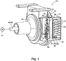
- Figs. 1 to 6 are drawings for describing one embodiment of the invention.
- Figs. 1 and 2 are for explaining the overall configuration of the scroll fluid machine.
- a scroll fluid machine 10 includes a fixed scroll 20 and an orbiting scroll 30 as main components.
- the fixed scroll 20 and the orbiting scroll 30 move relative to each other to act on a fluid.
- the illustrated scroll fluid machine 10 further includes a case 15 and a drive mechanism 40 in addition to the fixed scroll 20 and the orbiting scroll 30.
- the fixed scroll 20 is fixed to the case 15 via a fastener 13.
- the orbiting scroll 30 is disposed in a space defined by the case 15 and the fixed scroll 20.
- the orbiting scroll 30 faces the fixed scroll 20 in an axial direction "ad" defined by the drive mechanism 40.
- a working room 11 is formed between the fixed scroll 20 and the orbiting scroll 30. In the scroll fluid machine 10, the orbiting scroll 30 moves relatively to the fixed scroll 20 to act on the fluid in the working room 11.
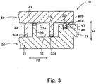
- Fig. 3 is a partially enlarged view of Fig. 2
- Fig. 6 is a perspective view of the fixed scroll 20 included in the scroll fluid machine 10.
- the fixed scroll 20 has a base plate portion 21 having a substantially circular disk profile.
- An annular wall portion 22 is provided on the peripheral edge of the base plate portion 21.
- the annular wall portion 22 extends from the base plate portion 21 toward the orbiting scroll 30 in a direction in which the fixed scroll and the orbiting scroll 30 face each other, in other words, in the axial direction "ad" of the scroll fluid machine 10.
- the annular wall portion 22 of the fixed scroll 20 is fixed to the case 15 with the fastener 13.
- the annular wall portion 22 defines a surface (contact surface, opposing surface) "sfa" that faces the orbiting scroll 30.
- the surface "sfa” is flat.
- the surface "sfa” contacts the orbiting scroll 30 during the operation of the scroll fluid machine 10.
- a groove 25 is formed in the perimeter (in particular, circle's perimeter) of the surface "sfa”.
- the biasing means 46 and the dustproof seal member 47 are provided in the groove 25. In a precise sense, the dustproof seal member 47 contacts the orbiting scroll 30.
- the biasing means 46 presses the dustproof seal member 47 in the axial direction "ad” to bring the dustproof seal member 47 into contact with the orbiting scroll 30. Sealing between the fixed scroll 20 and the orbiting scroll 30 is effectively provided by the dustproof seal member 47 urged by the biasing means.
- a fixed wrap 23 is provided in a region surrounded by the annular wall portion 22 of the base plate portion 21.
- the fixed wrap 23 is a standing wall provided along a spiral path when observed from the axial direction "ad" of the scroll fluid machine 10.
- the fixed wrap 23 extends from the base plate portion 21 toward the orbiting scroll 30 in the axial direction "ad" of the scroll fluid machine 10.
- a tip seal 23a is provided at the tip of the fixed wrap 23, .
- the tip seal 23a contacts the orbiting scroll 30.
- the tip seal 23a is formed of a material having excellent airtightness such as rubber or resin and seals between the fixed wrap 23 and the orbiting scroll 30.
- the base plate portion 21 has through holes.
- the through holes form an inlet 11a and an outlet 11b respectively for communicating the working room 11 with the outside.
- the inlet 11a is provided at the outer peripheral portion along the spiral path of the fixed wrap 23 and the outlet 11b is provided at the center of the spiral path of the fixed wrap 23.
- heat radiation fins 24, a cover 26, and side wall portion 27 are provided on the base plate portion 21 on the side opposite to the fixed wrap 23.
- the cover member 26 is formed in a plate shape and is disposed to face the base plate portion 21.
- a pair of side wall portions 27 are provided between the base plate portion 21 and the cover 26. Each side wall portion 27 extends in the axial direction "ad" of the scroll fluid machine 10 and connects the base plate portion 21 and the cover 26.
- a tubular flow path is defined by the base plate portion 21, the cover 26, and the pair of side wall portions 27, with an inlet port Sa2 and an outlet port Sb2 formed at both ends.
- a cooling fluid from a delivery mechanism 70 which will be described later, passes through the flow path.
- the plurality of heat radiation fins 24 are provided between the base plate portion 21 and the cover 26 where is in the flow path. The heat radiation fins 24 extend between the base plate portion 21 and the cover 26 in the axial direction "ad" of the scroll fluid machine 10.
- the orbiting scroll 30 disposed in the space S orbits while being in contact with the fixed scroll 20.
- the orbiting scroll 30 has a base plate portion 31 arranged to face the fixed scroll 20.
- the base plate portion 31 has a first surface 31a facing the fixed scroll 20 and a second surface 31b facing the side opposite to the fixed scroll 20.
- An orbiting wrap 33 is formed in a region of the first surface 31a of the base plate portion 31 facing the working room 11.
- the orbiting wrap 33 is a wall portion standing along a spiral path when observed from the axial direction "ad" of the scroll fluid machine 10 and has a configuration complementary to the fixed wrap 23.
- the orbiting wrap 33 extends from the base plate portion 31 toward the fixed scroll 20 in the axial direction "ad” of the scroll fluid machine 10.
- a tip seal 33a is provided as shown in Fig. 3 .
- the tip seal 33a contacts the fixed scroll 20.
- the tip seal 33a is formed of a material having excellent hermeticity such as rubber and resin and hermetically seals between the orbiting wrap 33 and the fixed scroll 20.
- a circumferential surface “sfb” (contact surface) is formed on the first surface 31a of the base plate portion 31 in an outer peripheral of a region where the orbiting wrap 33 is provided.
- the surface “sfb” is flat.
- the surface “sfb” of the orbiting scroll 30 contacts the surface “sfa” of the fixed scroll 20 during the operation of the scroll fluid machine 10 and hermetically seals between the fixed scroll 20 and the orbiting scroll 30. More specifically, the surface “sfb” of the orbiting scroll 30 contacts the dust-proof seal member 47 provided on the surface "sfa" of the fixed scroll 20 during the operation of the scroll fluid machine 10.
- heat radiation fins 34 and a connecting boss 35 are provided on the second surface 31b of the base plate portion 31.
- the heat radiation fins 34 and the connecting boss 35 extend in the axial direction "ad" from the second surface 31b.
- the drive mechanism 40 is a mechanism for moving the orbiting scroll 30 relative to the fixed scroll 20.
- the drive mechanism 40 causes the orbiting scroll 30 to orbit relative to the fixed scroll 20 in a plane orthogonal to the axial direction "ad" of the scroll fluid machine 10.
- the orbiting scroll 30 is driven by the drive mechanism 40 to translate relative to the fixed scroll 20, in particular, translate along a circumferential path.
- the drive mechanism 40 has an electric motor 41 that supplies a rotational force and a conversion mechanism 42 that converts the rotational motion output by the electric motor 41 into a translational motion along the circumferential orbit.
- the conversion mechanism 42 various known configurations may be adopted, for example, the configuration disclosed in the aforementioned patent literature (JPH7-208353A) may be adopted.
- the conversion mechanism 42 includes a crankshaft 43 rotatally driven by the electric motor 41 and a bearing 44 fixed in the connecting boss 35 of the orbiting scroll 30.
- the crankshaft 43 includes a first shaft 43a disposed on a rotation axis "ra” of the electric motor 41 and rotationally driven by the electric motor 41, and a second shaft portion 43b defining an eccentric axis "ea” decentered from the rotation axis "ra”.
- the second shaft 43a is held by a bearing 44.
- the first shaft 43a is rotationally driven, the second shaft 43b moves in a circle about the rotation axis "ra.”
- the radius of the circle corresponds to the amount of eccentricity from the rotation axis "ra” to the eccentric axis "ea”.
- the orbiting scroll 30 is then capable of rotating about the eccentric axis "ea” with respect to the second shaft 43b via the bearing 44.
- the orbiting scroll 30 is able to orbit relative to the fixed scroll 20 through the rotation output by the electric motor 41.
- a mechanism for restricting the rotation of the orbiting scroll 30 relative to the fixed scroll 20 for example, a crankshaft or the like may be additionally provided.
- the axial direction “ad” of the scroll fluid machine 10 is defined by the rotation axis "ra” of the electric motor 41.
- the axial direction “ad” of the scroll fluid machine 10 is the direction parallel to the rotation axis "ra” of the electric motor 41. In the illustrated example, the axial direction “ad” is also parallel to the eccentric axis "ea”.
- the fixed scroll 20 opposes the orbiting scroll 30 in the axial direction "ad” of the scroll fluid machine 10.
- the case 15, the fixed scroll 20 and the orbiting scroll 30 are made of metal having high strength and excellent heat resistance.
- aluminum or aluminum alloy is advantageous in that it is lightweight and excellent in heat dissipation property.
- the biasing means 46 is formed of a material itself having elasticity, a material having form elasticity, and the like. In the example shown in Fig. 3 , the biasing means 46 is formed of a rubber tube.
- the dustproof seal member 47 is made of a material having abrasion resistance and high sealing property when used with the surface "sfb" of the orbiting scroll 30, for example, rubber, resin, or the like.
- the scroll fluid machine 10 when the orbiting scroll 30 orbits relative to the fixed scroll 20 as driven by the drive mechanism 40, the fixed wrap 23 and the orbiting wrap 33 repeatedly approach and separate to/from each other in the radial direction "rd" orthogonal to the axial direction "ad” in regions along the spiral path of the fixed wrap 23.
- a working fluid as an internal medium is compressed or expanded along the spiral path of the fixed wrap 23 in the working room 11.
- the air is compressed from the outer peripheral region along the spiral path of the fixed wrap 23 toward the center region.
- the air with increased pressure is obtained and supplied to the outside through the outlet 11b.
- the air is sucked from the inlet 11a located at the outer peripheral portion along the spiral path of the fixed wrap 23.
- the scroll fluid machine 10 functions as a compressor.
- the working fluid which is the air in the illustrated example
- the working fluid is compressed in the working chamber 11 between the orbiting scroll 30 and the fixed scroll 20 and consequently heat is generated. Due to this heat generation, in particular, the fixed scroll 20 and the orbiting scroll 30 are heated. When the fixed scroll 20 and the orbiting scroll 30 are heated, thermal deformation may occur, and the sealing between the fixed scroll 20 and the orbiting scroll 30 may become insufficient.
- the delivery mechanism 70 for delivering a cooling fluid "cf" to the scroll fluid machine 10.
- the cooling fluid "cf” can efficiently cool the scroll fluid machine 10 by performing heat exchange with the heat radiation fins 24, 34 of the fixed scroll 20 and the orbiting scroll 30.
- the scroll fluid machine 10 is provided with an inlet port Sa and an outlet port Sb that are communicated with the space S.
- the tubular flow path is defined by the base plate portion 21, the cover 26, and the pair of side wall portions 27, with the inlet port Sa2 and the outlet port Sb2 formed at both ends.
- the cooling fluid "cf' delivered from the delivery mechanism 70 is introduced into the inlet port Sa and the inlet port Sa2.
- the cooling fluid "cf' entered into the space S from the inlet port Sa passes through the outlet port Sb to flow out from the space S.
- the cooling fluid "cf' passing through the space S can efficiently cool the orbiting scroll 30.
- the cooling fluid "cf' flowing into the flow path in the fixed scroll 20 from the inlet port Sa2 passes through the outlet port Sb2 to flow out from the flow path in the fixed scroll 20.
- the cooling fluid "cf' flowing through the flow path in the fixed scroll 20 can efficiently cool the fixed scroll 20.
- the cooling fluid "cf' may be used as the cooling fluid "cf' that is delivered from the delivery mechanism 70 to the scroll fluid machine 10.
- the air around the scroll fluid machine 10 is preferably used as the cooling fluid "cf' since the configuration of the machine can be simplified and the operation cost of the scroll fluid machine 10 can be reduced.
- the delivery mechanism 70 is configured as a blower.
- a duct or the like may be provided between the delivery mechanism 70 and the inlet port Sa of the scroll fluid machine 10 to supply the cooling fluid "cf" only to the internal space S of the scroll fluid machine 10.
- the delivery mechanism 70 may supply the cooling fluid "cf' to both the inner space S and the outer surface of the scroll fluid machine 10.
- Scroll fluid machines serving as compressors are used in various fields including vehicles such as train cars and automobiles.
- a conventional scroll fluid machine is used under dusty environment, a trouble could occur such that the life of the tip seal provided at the tip of the wrap becomes extremely short.
- a scroll fluid machine used as an air compressor mounted on a railway vehicle may be used in various outdoor environments where railway vehicles travel, such as urban areas, rural areas, and mountain forest areas. Therefore, such scroll fluid machines are exposed to more dusty environment as compared to ones used in door. Further, as the environment changes depending on operation area and time of railway vehicles, it is difficult to take permanent measures.
- the air-cooled scroll fluid machines may be configured as oilless, and unlike oil scroll fluid machines that includes cooling oil in the working room, it has been regarded as a major advantage of the oilless fluid machines that it is not necessary to perform maintenance over a certain period of time. In this respect, early deterioration of the tip seal occurred when the machine is used under dusty environment can be a reason for limiting the fields where the scroll fluid machines are used.
- the inventors of the present application investigated the cause of early deterioration of the tip seal, and found that foreign substances such as dust in the environment flow into the working room through contact points between the fixed scroll and the orbiting scroll, and the foreign substances enter into between the tip seal material and each scroll, which causes abrasion and deterioration of the tip seal. Further studies have revealed that a part of the cooling fluid for cooling the scroll is directed to a gap between the fixed scroll and the orbiting scroll, and the cooling fluid directed to the gap guides dust into the working room. This result is consistent with the fact that the above problem becomes more conspicuous in dusty environments.
- the scroll fluid machine 10 further includes a flow regulator (flow regulation means) 50.
- the flow regulator 50 regulates the air flow from the outside to an outer peripheral portion of the region where the fixed scroll 20 and the orbiting scroll 30 face each other. More specifically, the flow regulator 50 is disposed in the outer peripheral portion surrounding the working room in the area where the fixed scroll 20 and the orbiting scroll 30 are opposed and at a position where the gap between the fixed scroll 20 and the orbiting scroll 30 opens.
- the flow regulator regulates a fluid that comes from the outside, which is the side opposite to the working chamber, to the portion where the regulator disposed such that the flow rate or speed of the fluid is reduced.
- the flow regulator 50 faces the inlet port Sa or the inlet port Sa.
- the flow regulator 50 is provided at the inlet port Sa or between the inlet port Sa and the orbiting scroll 30.
- the flow regulator 50 regulates the flow of the cooling fluid "cf' so as to prevent the cooling fluid "cf” supplied from the delivery mechanism 70 from directly flowing into the gap between the fixed scroll 20 and the orbiting scroll 30.
- Regulation of the airflow encompasses reduction of the flow speed of the cooling fluid "cf" flowing to the gap between the fixed scroll 20 and the orbiting scroll 30 or reduction of the flow rate of the cooling fluid "cf” flowing to the gap by the flow regulator 50.
- the flow regulator 50 includes an attachment piece 51, a shielding plate 55, and an extension portion 59.
- the attachment piece 51 is used to fix the flow regulator 50 to the case 15, the fixed scroll 20 or the orbiting scroll 30.
- a fastener 52 penetrates the attachment piece 51 and is fixed to the case 15, so that the flow regulator 50 is supported by the case 15 at a predetermined position.
- the shielding plate 55 and the extension portion 59 are provided for adjusting the flow of the cooling fluid "cf" delivered by the delivery mechanism 70.
- the flow regulator 50 is formed by bending a single metal plate.
- the flow regulator 50 is formed using the same material as the case 15, the fixed scroll 20 or the orbiting scroll 30, for example, the same aluminum or aluminum alloy.
- the flow regulator 50 made of the same material as the case 15, the fixed scroll 20, or the orbiting scroll 30, it is possible to effectively reduce the difference in thermal expansion between the flow regulator 50 and the case 15 and/or the scrolls 20, 30. Thereby it is possible to effectively prevent the thermal deformation of the flow regulator 50.
- the shielding plate 55 As shown in Fig. 2 , the shielding plate 55 is situated on the extension of the surface "sfb" of the orbiting scroll 30 that contacts the fixed scroll 20. The shielding plate 55 extends nonparallel to the surface "sfb" of the orbiting scroll 30. Therefore, the shielding plate 55 can deflect a traveling direction of the cooling fluid "cf' delivered by the delivery mechanism 70 from the gap between the fixed scroll 20 and the orbiting scroll 30.
- the surface "sfb" of the orbiting scroll 30 is a flat surface that extends in the radial direction “rd” orthogonal to the axial direction "ad”.
- the shielding plate 55 extends in a direction perpendicular to the surface "sfb" of the orbiting scroll 30.
- the direction connecting the inlet port Sa and the outlet port Sb is preferably along the radial direction "rd” as shown in Fig. 2 .
- the shielding plate 55 not only faces the surface "sfb" of the orbiting scroll 30 from the radial direction "rd", but also faces the surface (opposing surface) "sfa” of the fixed scroll 20 from the radial direction "rd”.
- the shielding plate 55 is disposed at a position where the plate covers the gap between the fixed scroll 20 and the orbiting scroll 30 from the radial direction "rd”. According to the shielding plate 55, it is possible to effectively shield the gap between the fixed scroll 20 and the orbiting scroll 30 from the radial direction "rd". Thus, it is possible to effectively prevent foreign substances from flowing into the working room 11.
- a first end portion (one end portion) 55a of the shielding plate 55 extends further than the surface "sfb" of the orbiting scroll 30 toward the fixed scroll 20 in the direction "ad” in which the fixed scroll 20 and the orbiting scroll 30 face each other (that is, in the axial direction).
- a second end portion (the other end portion) 55b of the shielding plate 55 extends further than the second surface 31b of the base plate portion 31 in the direction away from the fixed scroll 20.
- the shielding plate 55 is arranged at a position where the shielding plate covers the base plate portion 31 of the orbiting scroll 30 over the entire thickness of the base plate portion from the radial direction "rd” in at least a part of the circumferential region surrounding the orbiting scroll 30.
- the heat radiation fins 34 are provided on the second surface 31b of the base plate portion 31.
- the second end portion 55b of the shielding plate 55 is situated between the second surface 31b and a tip 34a of the heat radiation fin 34 most distant from the base plate portion 31.
- the cooling fluid "cf" that has been deflected by the shielding plate 55 is directed to the heat radiation fins 34 of the orbiting scroll 30. Consequently it is possible to effectively prevent foreign substances from entering into the working room 11 while the orbiting scroll 30 is efficiently cooled.
- the extension portion 59 extends from the shielding plate 55 toward the orbiting scroll 30.
- Fig. 4 is a perspective view of the scroll fluid machine 10 with the case 15 and the drive mechanism 40 removed.
- the extension portion 59 extends from the second end portion 55b of the shielding plate 55.
- the extension portion 59 is formed in a plate shape and extends in the radial direction "rd" perpendicular to the axial direction "ad". That is, the extension portion 59 extends perpendicularly to the plane in which the shielding plate 55 extends, and extends in a plane parallel to the surface "sfb" of the orbiting scroll 30.
- the extension portion 59 By providing the extension portion 59, the flow speed of the cooling fluid "cf" flowing toward the gap between the fixed scroll 20 and the orbiting scroll 30 is greatly reduced by bypassing the extension portion 59, and the amount of the cooling fluid "cf" flowing toward the gap is also greatly reduced.
- the extension portion 59 is situated between the tip 34a of the heat radiation fin 34 of the orbiting scroll 30 and the second surface 31b of the base plate portion 31.
- the cooling fluid "cf' whose traveling direction has been regulated by the extension portion 59 is directed toward the heat radiation fins 34 of the orbiting scroll 30, and therefore it is possible to effectively prevent foreign substances from entering into the working room 11 while efficiently cooling the orbiting scroll 30.
- FIG. 5 is a plan view of the scroll fluid machine 10 with the case 15 and the drive mechanism 40 removed. Since the edge 59a of the extension portion 59 situated on the side remote from the shielding plate 55 has the arc profile, the extension portion 59 can be disposed close to the orbiting scroll 30 and thereby it is possible to reduce the gap between the orbiting scroll 30 and the extension portion 59. In this case, the flow rate of the cooling fluid "cf' flowing toward the gap between the fixed scroll 20 and the orbiting scroll 30 is more effectively reduced, and the flow speed of the cooling fluid "cf" toward the gap is more effectively reduced.
- the profile of the edge 59a of the extension portion 59 is along a circular arc centered on the rotation axis "ra" of the electric motor 41, that is, concentric with the circumferential orbit of the translational movement of the orbiting scroll 30.
- the edge 59a having such a profile, it is possible to arrange the extension portion 59 closer to the orbiting scroll 30.
- the scroll fluid machine 10 includes the fixed scroll 20 and the orbiting scroll 30 that orbits while contacting the fixed scroll 20. Further, the scroll fluid machine 10 includes the flow regulator 50 for regulating the flow of the cooling fluid "cf".
- the flow regulator 50 (the shielding plate 55) regulates the air flow flowing toward between the fixed scroll 20 and the orbiting scroll 30. In other words, the flow regulator 50 regulates the air flow from the outside to the outer peripheral portion of the region where the fixed scroll 20 and the orbiting scroll 30 face each other. In the scroll fluid machine 10 described above, it is possible to effectively prevent a large amount of the cooling fluid "cf" from flowing at high pressure or high speed into the space between the fixed scroll 20 and the orbiting scroll 30 where should be sealed.
- the flow regulator 50 (the shielding plate 55) is situated on the extension of the surface "sfb" of the orbiting scroll 30 that contacts the fixed scroll 20.
- the flow regulator 50 (the shielding plate 55) extends in a direction non-parallel to the surface "sfb".
- the flow regulator 50 shields the portion between the fixed scroll 20 and the orbiting scroll 30 from the direction parallel to the sliding contact surface "sfb". Thereby, it is possible to more effectively prevent the cooling fluid "cf' from flowing into the working room 11 together with the dust.
- the scroll fluid machine 10 further includes the case 15 that defines, with the fixed scroll 20, the space S in which the orbiting scroll 30 is disposed.
- the inlet port Sa and the outlet port Sb for the cooling fluid "cf" communicating with the space S are provided.
- the flow regulator 50 faces the inlet port Sa or the inlet port Sa2.
- the flow regulator 50 is disposed close to the orbiting scroll 30 and thereby it is possible to more effectively prevent the inflow of dust into the working room 11.
- the flow regulator 50 is provided between the orbiting scroll 30 and the inlet port Sa or the inlet port Sa2. Thus, the flow regulator 50 is disposed close to the orbiting scroll 30 and thereby it is possible to more effectively prevent the inflow of dust into the working room 11.
- the orbiting scroll 30 has the base plate portion 31 that has the first surface 31a facing the working room 11 and including the surface "sfb" and the second surface 31b facing away from the working room.
- one end portion (the first end portion) 55a of the shielding plate 55 extends further than the surface "sfb" toward the fixed scroll 20
- the other end portion (the second end portion) 55b of the shielding plate 55 extends further than the second surface 31b in the direction away from the fixed scroll 20.
- the shielding plate 55 covers the base plate portion 31 over the entire thickness of the base plate portion from the radial direction "rd” in at least a part of the circumferential region surrounding the orbiting scroll 30.
- the shielding plate 55 of the flow regulator 50 shields the contact portion between the fixed scroll 20 and the orbiting scroll 30 from the direction parallel to the surface "sfb", but also it can guide the cooling fluid "cf" toward the second surface 31b of the base plate portion 31. Thereby, it is possible to more effectively prevent the cooling fluid "cf” from flowing into the working room 11 together with the dust.
- the orbiting scroll 30 further includes heat radiation fins 34 extending from the second surface 31b of the base plate portion 31.
- the other end portion 55b of the shielding plate 55 (the flow regulator 50) is situated between the second surface 31b and the tip 34a of the heat radiation fin 34 distant from the base plate portion 31.
- the shielding plate 55 of the flow regulator 50 shields the contact portion between the fixed scroll 20 and the orbiting scroll 30 from the direction parallel to the surface "sfb", but also it can guide the cooling fluid "cf' toward the heat radiation fins 34 provided on the side of the second surface 31b of the base plate portion 31.
- the flow regulator 50 includes the shielding plate 55 extending in the direction non-parallel to the surface "sfb", and the extension portion 59 extending from the shielding plate 55 toward the fixed scroll 20.
- the cooling fluid "cf” is unable to reach between the fixed scroll 20 and the orbiting scroll 30 unless it bypasses the extension portion 59.
- the extension portion 59 can effectively prevent the cooling fluid "cf” from flowing into the portion to be sealed between the fixed scroll 20 and the orbiting scroll 30. This also greatly reduces the flow speed of the cooling fluid "cf' flowing into the portion to be sealed between the fixed scroll 20 and the orbiting scroll 30 and greatly reduces the flow rate of the cooling fluid "cf' flowing into the portion. Thereby, it is possible to more effectively prevent the cooling fluid "cf” from flowing into the working room 11 together with the dust.
- the extension portion 59 is situated between the tip 34a of the heat radiation fin 34 and the second surface 31b of the base plate portion 31 in the axial direction "ad".
- this scroll fluid machine 10 it is possible to more effectively prevent the cooling fluid "cf” from flowing into the portion to be sealed between the fixed scroll 20 and the orbiting scroll 30, and to reliably guide the cooling fluid "cf” to the radiation fins 34 provided on the second surface 31b of the base plate portion 31.
- the edge 59a of the extension portion 59 opposite to the side connected to the shielding plate 55 has an arc profile.
- the extension portion 59 can be extended to the vicinity of the orbiting scroll 30 that is capable of orbiting relative to the fixed scroll 20.
- the shielding plate portion 55 and the extension portion 59 may be formed of a bent metal plate.
- the flow regulator 50 configured in this manner has a simple structure and can be manufactured at low cost. Further, in a typical general scroll fluid machine 10, the fixed scroll 20, the orbiting scroll 30, and the case 15 are made of metal, so that the flow regulator 50 made of metal hardly has a difference in thermal expansion from these components. Therefore, it is possible to effectively prevent thermal deformation of the flow regulator 50, whereby the flow regulator 50 can stably achieve its expected function.
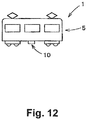
- the scroll fluid machine 10 described above is used as an air compressor in a vehicle 1 as shown in Fig. 12 .
- a railway vehicle will be described as an example of the vehicle 1, the invention is not limited to this and can also be applied to work vehicles such as trucks, buses, vehicles for work at height, and the like.
- the vehicle 1 shown in Fig. 12 includes a vehicle body 5 and the scroll fluid machine 10 mounted on the vehicle body 5.
- the shielding plate 55 of the flow regulator 50 extends in parallel to the axial direction "ad" has been described.
- the invention is not limited to this example.
- the shielding plate 55 may extend in a direction inclined with respect to the axial direction "ad” as shown in Fig. 7 .
- the shielding plate 55 shown in Fig. 7 is situated on a line extended from the surface "sfb" of the orbiting scroll 30 and extends in a direction non-parallel to the surface "sfb".
- the shielding plate 55 of the flow regulator 50 configured this way can also shield the contact portion between the fixed scroll 20 and the orbiting scroll 30 from the direction parallel to the surface "sfb" in the same manner as the above-described embodiment, and it is possible to effectively prevent foreign substances from flowing into the working room 11. Further, the first end portion 55a of the shielding plate 55 shown in Fig. 7 is situated closer to the fixed scroll 20 than the surface "sfb" of the orbiting scroll 30 in the axial direction "ad".
- the second end portion 55b of the shielding plate 55 is positioned on the side away from the fixed scroll 20 with respect to the second surface 31b of the base plate portion 31 in the axial direction "ad", and is situated between the tip end 34a of the heat radiation fin 34 and the second surface 31b.
- the flow regulator 50 has the extension portion 59 separately from the shielding plate 55, however the invention is not limited thereto. As shown in Fig. 7 , the extension portion 59 may be omitted. In the example shown in Fig. 7 , the shielding plate 55 is inclined with respect to the radial direction "rd". More specifically, the shielding plate 55 is disposed closer to the orbiting scroll 30 in the radial direction "rd” as it is disposed more away from the fixed scroll 20 in the axial direction "ad".
- the shielding plate 55 is configured in this way, since the second end portion 55b of the shielding plate 55 is disposed close to the orbiting scroll 30, it is possible to effectively prevent foreign substances from flowing into the working room 11 in the same manner as the extension portion 59 in the above-described embodiment.
- the flow regulator 50 is provided at the inlet port Sa in the above-described embodiment, however the invention is not limited to this example.
- the flow regulator 50 may be provided at any position within the space S between the inlet port Sa and the orbiting scroll 30. In this case, the flow regulator 50 is disposed closer to the orbiting scroll 30 and thereby it is possible to more effectively prevent the inflow of foreign substances into the working room 11.
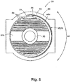
- the shielding plate 55 faces the surface "sfb" in the region where the inlet port Sa is provided in the circumferential direction "cd" surrounding the orbiting scroll 30 as shown in Fig.
- the shielding plate 55 covers the surface "sfb" of the orbiting scroll 30 from the radial direction "rd” over an angular range of 90° or more, preferably over an angular range of 180° or more, more preferably over an angular range of 270°, and most preferably over 360° along the circumferential direction "cd".
- Fig. 1 In the example shown in Fig.
- the shielding plate 55 extends along the circle centered on the rotation axis "ra" of the electric motor 41, that is, a circle concentric with the circumferential orbit of the translational motion of the orbiting scroll 30, and surrounds the surface "sfb" of the orbiting scroll 30 from the radial direction "rd” over an angular range of 180°.
- the extension portion 59 connected to the shielding plate 55 extend from the shielding plate 55 along the flow direction of the cooling fluid "cf" from the inlet port Sa to the outlet port Sb.
- the extension portion 59 preferably extends from the shielding plate portion 55 that extends in the circumferential direction "cd" toward the center in the radial direction in the region of the angular range of 180° along the circumferential direction "cd” about the inlet port Sa.
- the extension portion 59 extends radially outward (the side opposite to the center side) from the shielding plate 55 that extends in the circumferential direction "cd”.
- the flow regulator (flow regulation means) 50 formed as a plate member has been illustrated in the above-described embodiment, the invention is not limited thereto.
- the flow regulator (flow regulation means) 50 may be configured as various means capable of restricting the air flow directed between the fixed scroll 20 and the orbiting scroll 30.
- the flow regulator (flow regulation means) 50 may be an air curtain.
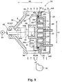
- a flow regulator (a second flow regulator, a flow guiding member, flow guiding means) 60 may be provided in the scroll fluid machine 10 as shown in Figs. 10 and 11 .
- the flow regulator 60 is also capable of regulating the air flow from the outside to the outer peripheral portion of the region where the fixed scroll 20 and the orbiting scroll 30 face each other. More specifically, the flow regulator (flow guiding member) 60 guides the flow of the cooling fluid "cf" flowing from the inlet port Sa to the outlet port Sb to the side away from the fixed scroll 20 in the axial direction "ad" where the fixed scroll 20 and the orbiting scroll 30 face each other.
- the flow regulator (flow guiding member) 60 shown in Figs. 10 and 11 extends from the orbiting scroll 30 toward the side away from the fixed scroll 20 in the axial direction "ad” where the fixed scroll 20 and the orbiting scroll 30 face each other.
- the flow regulator (flow guiding member) 60 has a base end portion 60a connected to the orbiting scroll 30, and a distal end portion 60b remote from the orbiting scroll 30. In the axial direction "ad" of the scroll fluid machine 10, the distal end portion 60b is situated more distant from the portion to be sealed between the fixed scroll 20 and the orbiting scroll 30 than the base end portion 60a.
- the flow regulator (flow guiding member) 60 extends into the space S from the second surface 31b of the base plate portion 31 of the orbiting scroll 30. In the example shown in Figs. 10 and 11 , the flow regulator (flow guiding member) 60 is situated between the inlet port Sa and the outlet port Sb.
- the flow regulator (flow guiding member) 60 is situated between the flow regulator 50 and the outlet port Sb.
- the flow regulator 50 is situated between the flow regulator (flow guiding member) 60 and the inlet port Sa.
- the distance from the flow regulator (flow guiding member) 60 to the outlet port Sb is smaller than the distance from the flow regulator (flow guiding member) 60 to the inlet port Sa.
- the flow regulator (flow guiding member) 60 is situated in the vicinity of the outlet port Sb.
- the flow regulator (flow guiding member) 60 shown in Fig. 10 extends from the orbiting scroll 30 such that it is disposed closer to the outlet port Sb and away from the inlet port Sa in the direction connecting the inlet port Sa and the outlet port Sb. Therefore, the flow of the cooling fluid "cf' away from the inlet port Sa toward the outlet port Sb can be guided so as to be separated from the portion to be sealed between the fixed scroll 20 and the movable scroll 30 without significantly disturbing it can do.
- the flow regulator (flow guiding member) 60 shown in Fig. 11 includes a guiding plate 61 that extends from the orbiting scroll 30 and a flow regulating plate 62 that extends from an end of the guiding plate 61 situated away from the orbiting scroll 30.
- the guiding plate 61 extends substantially in parallel with the axial direction "ad" of the scroll fluid machine 10.
- the flow regulating plate 62 extends toward the outlet port Sb substantially in parallel with the direction connecting the inlet port Sa and the outlet port Sb.
- the distal end portion 60b of the flow regulator (flow guiding member) 60 is situated closer to the outlet port Sb than the end of the base plate portion 21 in the direction connecting the inlet port Sa and the outlet port Sb.
- the flow regulator 50 and the flow regulator (flow guiding member) 60 in the above-described embodiment respectively have a plate-like cross section, they may have a different cross section such as a curved shape.
- the cross-sectional shape may be made into a curve. In the case of a plate-like cross section with straight lines, molding is relatively easy.
Landscapes
- Engineering & Computer Science (AREA)
- Mechanical Engineering (AREA)
- General Engineering & Computer Science (AREA)
- Rotary Pumps (AREA)
- Applications Or Details Of Rotary Compressors (AREA)
Applications Claiming Priority (2)
| Application Number | Priority Date | Filing Date | Title |
|---|---|---|---|
| JP2016256830 | 2016-12-28 | ||
| PCT/JP2017/046523 WO2018124008A1 (ja) | 2016-12-28 | 2017-12-26 | スクロール式流体機械および車両 |
Publications (2)
| Publication Number | Publication Date |
|---|---|
| EP3564530A1 true EP3564530A1 (de) | 2019-11-06 |
| EP3564530A4 EP3564530A4 (de) | 2020-05-27 |
Family
ID=62710657
Family Applications (1)
| Application Number | Title | Priority Date | Filing Date |
|---|---|---|---|
| EP17885916.1A Withdrawn EP3564530A4 (de) | 2016-12-28 | 2017-12-26 | Spiralfluidmaschine und fahrzeug |
Country Status (5)
| Country | Link |
|---|---|
| EP (1) | EP3564530A4 (de) |
| JP (1) | JP6907235B2 (de) |
| CN (1) | CN110073106B (de) |
| TW (1) | TWI746757B (de) |
| WO (1) | WO2018124008A1 (de) |
Family Cites Families (11)
| Publication number | Priority date | Publication date | Assignee | Title |
|---|---|---|---|---|
| JPH02173380A (ja) * | 1988-12-24 | 1990-07-04 | Hitachi Ltd | スクロール圧縮機 |
| JP2753317B2 (ja) * | 1989-03-20 | 1998-05-20 | 株式会社日立製作所 | スクロール流体機械 |
| JPH07208353A (ja) | 1994-01-27 | 1995-08-08 | Sanyo Electric Co Ltd | スクロール型無給油式流体機械 |
| JPH08261181A (ja) * | 1995-03-20 | 1996-10-08 | Tokico Ltd | スクロール式流体機械 |
| JP2000337275A (ja) * | 1999-05-25 | 2000-12-05 | Tokico Ltd | スクロール式流体機械 |
| US7309219B2 (en) * | 2003-12-26 | 2007-12-18 | Hitachi, Ltd. | Scroll type fluid machinery |
| JP5286108B2 (ja) * | 2009-03-02 | 2013-09-11 | 株式会社日立産機システム | スクロール式流体機械 |
| JP5001334B2 (ja) * | 2009-08-05 | 2012-08-15 | 株式会社日立産機システム | スクロール式流体機械 |
| JP5422609B2 (ja) * | 2011-06-10 | 2014-02-19 | 株式会社日立産機システム | スクロール式流体機械 |
| JP6214954B2 (ja) * | 2013-07-25 | 2017-10-18 | 三菱重工業株式会社 | スクロール圧縮機 |
| US11085444B2 (en) * | 2016-07-07 | 2021-08-10 | Hitachi Industrial Equipment Systems Co., Ltd. | Scroll-type fluid machine |
-
2017
- 2017-12-26 EP EP17885916.1A patent/EP3564530A4/de not_active Withdrawn
- 2017-12-26 CN CN201780077078.5A patent/CN110073106B/zh active Active
- 2017-12-26 JP JP2018559485A patent/JP6907235B2/ja active Active
- 2017-12-26 WO PCT/JP2017/046523 patent/WO2018124008A1/ja not_active Ceased
- 2017-12-28 TW TW106146210A patent/TWI746757B/zh active
Also Published As
| Publication number | Publication date |
|---|---|
| JP6907235B2 (ja) | 2021-07-21 |
| JPWO2018124008A1 (ja) | 2019-10-31 |
| CN110073106A (zh) | 2019-07-30 |
| EP3564530A4 (de) | 2020-05-27 |
| CN110073106B (zh) | 2022-01-28 |
| TW201833441A (zh) | 2018-09-16 |
| TWI746757B (zh) | 2021-11-21 |
| WO2018124008A1 (ja) | 2018-07-05 |
Similar Documents
| Publication | Publication Date | Title |
|---|---|---|
| US6336797B1 (en) | Oiless rotary scroll air compressor air inlet valve | |
| US20180355866A1 (en) | Dry vacuum scroll pump | |
| US8647085B2 (en) | Scroll fluid machine having a communication passage between an inner periphery of lip seal and an outer periphery of drive shaft or ring | |
| CN105102818B (zh) | 涡旋式流体机械 | |
| CN102985698A (zh) | 涡旋泵 | |
| CN109312738B (zh) | 涡旋式流体机械 | |
| EP3561304A1 (de) | Spiralverdichter und montageverfahren dafür | |
| US6283737B1 (en) | Oiless rotary scroll air compressor antirotation assembly | |
| CN109715950B (zh) | 涡旋式流体机械、密封构件以及密封件 | |
| EP1160454A2 (de) | Spiralverdichter | |
| CN101319672A (zh) | 涡旋压缩机 | |
| CN101160466A (zh) | 涡旋型流体机械 | |
| US6328545B1 (en) | Oiless rotary scroll air compressor crankshaft assembly | |
| EP3051135B1 (de) | Rollenelement und fluidmaschine mit rollen | |
| EP3564530A1 (de) | Spiralfluidmaschine und fahrzeug | |
| US6592345B2 (en) | Scroll compressor | |
| CN103486089B (zh) | 风扇罩和泵装置 | |
| CN110249130B (zh) | 具有棱柱形活塞的无油真空泵和相应的压缩机 | |
| CN110226040A (zh) | 涡旋型压缩机 | |
| JP6808510B2 (ja) | スクロール型圧縮機 | |
| US20130202416A1 (en) | Drive device | |
| CN116971986B (zh) | 涡旋压缩机 | |
| EP1160456A2 (de) | Spiralverdichter | |
| JP2021021385A (ja) | スクロール型流体機械 |
Legal Events
| Date | Code | Title | Description |
|---|---|---|---|
| STAA | Information on the status of an ep patent application or granted ep patent |
Free format text: STATUS: THE INTERNATIONAL PUBLICATION HAS BEEN MADE |
|
| PUAI | Public reference made under article 153(3) epc to a published international application that has entered the european phase |
Free format text: ORIGINAL CODE: 0009012 |
|
| STAA | Information on the status of an ep patent application or granted ep patent |
Free format text: STATUS: REQUEST FOR EXAMINATION WAS MADE |
|
| 17P | Request for examination filed |
Effective date: 20190712 |
|
| AK | Designated contracting states |
Kind code of ref document: A1 Designated state(s): AL AT BE BG CH CY CZ DE DK EE ES FI FR GB GR HR HU IE IS IT LI LT LU LV MC MK MT NL NO PL PT RO RS SE SI SK SM TR |
|
| AX | Request for extension of the european patent |
Extension state: BA ME |
|
| DAV | Request for validation of the european patent (deleted) | ||
| DAX | Request for extension of the european patent (deleted) | ||
| A4 | Supplementary search report drawn up and despatched |
Effective date: 20200430 |
|
| RIC1 | Information provided on ipc code assigned before grant |
Ipc: F04C 29/04 20060101ALI20200423BHEP Ipc: F04C 18/02 20060101AFI20200423BHEP |
|
| STAA | Information on the status of an ep patent application or granted ep patent |
Free format text: STATUS: EXAMINATION IS IN PROGRESS |
|
| 17Q | First examination report despatched |
Effective date: 20220413 |
|
| P01 | Opt-out of the competence of the unified patent court (upc) registered |
Effective date: 20230523 |
|
| GRAP | Despatch of communication of intention to grant a patent |
Free format text: ORIGINAL CODE: EPIDOSNIGR1 |
|
| STAA | Information on the status of an ep patent application or granted ep patent |
Free format text: STATUS: GRANT OF PATENT IS INTENDED |
|
| INTG | Intention to grant announced |
Effective date: 20231117 |
|
| STAA | Information on the status of an ep patent application or granted ep patent |
Free format text: STATUS: THE APPLICATION IS DEEMED TO BE WITHDRAWN |
|
| 18D | Application deemed to be withdrawn |
Effective date: 20240319 |