EP3564471A1 - Gelenkhebel für eine vorrichtung zur bewegung eines an einem möbelkorpus eines möbels aufgenommenen möbelteils - Google Patents
Gelenkhebel für eine vorrichtung zur bewegung eines an einem möbelkorpus eines möbels aufgenommenen möbelteils Download PDFInfo
- Publication number
- EP3564471A1 EP3564471A1 EP19168329.1A EP19168329A EP3564471A1 EP 3564471 A1 EP3564471 A1 EP 3564471A1 EP 19168329 A EP19168329 A EP 19168329A EP 3564471 A1 EP3564471 A1 EP 3564471A1
- Authority
- EP
- European Patent Office
- Prior art keywords
- furniture
- articulated lever
- lever
- articulated
- piece
- Prior art date
- Legal status (The legal status is an assumption and is not a legal conclusion. Google has not performed a legal analysis and makes no representation as to the accuracy of the status listed.)
- Granted
Links
Images


Classifications
-
- E—FIXED CONSTRUCTIONS
- E05—LOCKS; KEYS; WINDOW OR DOOR FITTINGS; SAFES
- E05D—HINGES OR SUSPENSION DEVICES FOR DOORS, WINDOWS OR WINGS
- E05D3/00—Hinges with pins
- E05D3/06—Hinges with pins with two or more pins
-
- A—HUMAN NECESSITIES
- A47—FURNITURE; DOMESTIC ARTICLES OR APPLIANCES; COFFEE MILLS; SPICE MILLS; SUCTION CLEANERS IN GENERAL
- A47B—TABLES; DESKS; OFFICE FURNITURE; CABINETS; DRAWERS; GENERAL DETAILS OF FURNITURE
- A47B96/00—Details of cabinets, racks or shelf units not covered by a single one of groups A47B43/00 - A47B95/00; General details of furniture
-
- E—FIXED CONSTRUCTIONS
- E05—LOCKS; KEYS; WINDOW OR DOOR FITTINGS; SAFES
- E05D—HINGES OR SUSPENSION DEVICES FOR DOORS, WINDOWS OR WINGS
- E05D3/00—Hinges with pins
- E05D3/06—Hinges with pins with two or more pins
- E05D3/16—Hinges with pins with two or more pins with seven parallel pins and four arms
-
- F—MECHANICAL ENGINEERING; LIGHTING; HEATING; WEAPONS; BLASTING
- F16—ENGINEERING ELEMENTS AND UNITS; GENERAL MEASURES FOR PRODUCING AND MAINTAINING EFFECTIVE FUNCTIONING OF MACHINES OR INSTALLATIONS; THERMAL INSULATION IN GENERAL
- F16C—SHAFTS; FLEXIBLE SHAFTS; ELEMENTS OR CRANKSHAFT MECHANISMS; ROTARY BODIES OTHER THAN GEARING ELEMENTS; BEARINGS
- F16C11/00—Pivots; Pivotal connections
- F16C11/04—Pivotal connections
-
- E—FIXED CONSTRUCTIONS
- E05—LOCKS; KEYS; WINDOW OR DOOR FITTINGS; SAFES
- E05D—HINGES OR SUSPENSION DEVICES FOR DOORS, WINDOWS OR WINGS
- E05D15/00—Suspension arrangements for wings
- E05D15/40—Suspension arrangements for wings supported on arms movable in vertical planes
-
- E—FIXED CONSTRUCTIONS
- E05—LOCKS; KEYS; WINDOW OR DOOR FITTINGS; SAFES
- E05D—HINGES OR SUSPENSION DEVICES FOR DOORS, WINDOWS OR WINGS
- E05D3/00—Hinges with pins
- E05D3/06—Hinges with pins with two or more pins
- E05D3/16—Hinges with pins with two or more pins with seven parallel pins and four arms
- E05D2003/163—Horizontal pivot-axis
-
- E—FIXED CONSTRUCTIONS
- E05—LOCKS; KEYS; WINDOW OR DOOR FITTINGS; SAFES
- E05D—HINGES OR SUSPENSION DEVICES FOR DOORS, WINDOWS OR WINGS
- E05D2700/00—Hinges or other suspension devices especially for doors or windows
- E05D2700/12—Suspension devices for doors or windows movable in a direction perpendicular to their plane or pivotable about an axis being situated at a considerable distance from the edge of the wing by means of pivot arms
-
- E—FIXED CONSTRUCTIONS
- E05—LOCKS; KEYS; WINDOW OR DOOR FITTINGS; SAFES
- E05Y—INDEXING SCHEME ASSOCIATED WITH SUBCLASSES E05D AND E05F, RELATING TO CONSTRUCTION ELEMENTS, ELECTRIC CONTROL, POWER SUPPLY, POWER SIGNAL OR TRANSMISSION, USER INTERFACES, MOUNTING OR COUPLING, DETAILS, ACCESSORIES, AUXILIARY OPERATIONS NOT OTHERWISE PROVIDED FOR, APPLICATION THEREOF
- E05Y2201/00—Constructional elements; Accessories therefor
- E05Y2201/60—Suspension or transmission members; Accessories therefor
- E05Y2201/622—Suspension or transmission members elements
- E05Y2201/624—Arms
-
- E—FIXED CONSTRUCTIONS
- E05—LOCKS; KEYS; WINDOW OR DOOR FITTINGS; SAFES
- E05Y—INDEXING SCHEME ASSOCIATED WITH SUBCLASSES E05D AND E05F, RELATING TO CONSTRUCTION ELEMENTS, ELECTRIC CONTROL, POWER SUPPLY, POWER SIGNAL OR TRANSMISSION, USER INTERFACES, MOUNTING OR COUPLING, DETAILS, ACCESSORIES, AUXILIARY OPERATIONS NOT OTHERWISE PROVIDED FOR, APPLICATION THEREOF
- E05Y2201/00—Constructional elements; Accessories therefor
- E05Y2201/60—Suspension or transmission members; Accessories therefor
- E05Y2201/622—Suspension or transmission members elements
- E05Y2201/624—Arms
- E05Y2201/626—Levers
-
- E—FIXED CONSTRUCTIONS
- E05—LOCKS; KEYS; WINDOW OR DOOR FITTINGS; SAFES
- E05Y—INDEXING SCHEME ASSOCIATED WITH SUBCLASSES E05D AND E05F, RELATING TO CONSTRUCTION ELEMENTS, ELECTRIC CONTROL, POWER SUPPLY, POWER SIGNAL OR TRANSMISSION, USER INTERFACES, MOUNTING OR COUPLING, DETAILS, ACCESSORIES, AUXILIARY OPERATIONS NOT OTHERWISE PROVIDED FOR, APPLICATION THEREOF
- E05Y2600/00—Mounting or coupling arrangements for elements provided for in this subclass
- E05Y2600/60—Mounting or coupling members; Accessories therefor
- E05Y2600/634—Spacers
-
- E—FIXED CONSTRUCTIONS
- E05—LOCKS; KEYS; WINDOW OR DOOR FITTINGS; SAFES
- E05Y—INDEXING SCHEME ASSOCIATED WITH SUBCLASSES E05D AND E05F, RELATING TO CONSTRUCTION ELEMENTS, ELECTRIC CONTROL, POWER SUPPLY, POWER SIGNAL OR TRANSMISSION, USER INTERFACES, MOUNTING OR COUPLING, DETAILS, ACCESSORIES, AUXILIARY OPERATIONS NOT OTHERWISE PROVIDED FOR, APPLICATION THEREOF
- E05Y2800/00—Details, accessories and auxiliary operations not otherwise provided for
- E05Y2800/40—Physical or chemical protection
- E05Y2800/412—Physical or chemical protection against friction
-
- E—FIXED CONSTRUCTIONS
- E05—LOCKS; KEYS; WINDOW OR DOOR FITTINGS; SAFES
- E05Y—INDEXING SCHEME ASSOCIATED WITH SUBCLASSES E05D AND E05F, RELATING TO CONSTRUCTION ELEMENTS, ELECTRIC CONTROL, POWER SUPPLY, POWER SIGNAL OR TRANSMISSION, USER INTERFACES, MOUNTING OR COUPLING, DETAILS, ACCESSORIES, AUXILIARY OPERATIONS NOT OTHERWISE PROVIDED FOR, APPLICATION THEREOF
- E05Y2800/00—Details, accessories and auxiliary operations not otherwise provided for
- E05Y2800/45—Manufacturing
- E05Y2800/465—Pressing
-
- E—FIXED CONSTRUCTIONS
- E05—LOCKS; KEYS; WINDOW OR DOOR FITTINGS; SAFES
- E05Y—INDEXING SCHEME ASSOCIATED WITH SUBCLASSES E05D AND E05F, RELATING TO CONSTRUCTION ELEMENTS, ELECTRIC CONTROL, POWER SUPPLY, POWER SIGNAL OR TRANSMISSION, USER INTERFACES, MOUNTING OR COUPLING, DETAILS, ACCESSORIES, AUXILIARY OPERATIONS NOT OTHERWISE PROVIDED FOR, APPLICATION THEREOF
- E05Y2900/00—Application of doors, windows, wings or fittings thereof
- E05Y2900/20—Application of doors, windows, wings or fittings thereof for furniture, e.g. cabinets
Definitions
- furniture sector guide means such as furniture hinges or flap fittings are known to move a furniture part relative to a furniture body can.
- the guide means must meet different requirements, in particular should be made accessible to the movement guide an interior of the furniture body or the movable furniture part to accommodate items in it or to be able to remove it.
- the object of the present invention is to improve an articulated lever for a device for moving a furniture part accommodated on a furniture carcass of a piece of furniture, so that this and in particular the device can be produced comparatively inexpensively and in particular the device has comparatively few individual parts.
- the invention is based on a toggle lever for a device for moving a furniture part received on a furniture carcass of a piece of furniture.
- the gist of the invention is seen in that the articulated lever has a spacer element in the form of a first and a second embossing, wherein the first embossment is present on a first side of the first articulated lever and the second embossment is present on a second side of the first articulated lever, wherein the first and second sides of the first articulated lever are opposite and spaced from each other with the first and second impressions being opposed, wherein the first embossment is in the azimuthal and / or radial directions about a center one elevation and a depression relative to a remaining one Surface of the first side and having the second embossing in the azimuthal and / or radial direction about a center, in particular around the center, a protrusion and a recess relative to a remaining surface of the second side.
- embossing is meant, for example, a formation of a surface area of the articulated lever, wherein the formation of the surface area is advantageously produced by a stamping process.
- the embossing forms to Example, a surface structure of the articulated lever.
- the first and the second embossing can be produced by a particular single embossing method, for example a particular single embossing step.
- the first embossment is given by the shape of an embossing die and the second embossing by the shape of an embossing die.
- first embossing and the second embossing is produced solely by the shape of an embossing stamp or an embossing die, in which case the first embossment is advantageously produced in a first production step and in a further production step the second embossment.
- the articulated lever is advantageously integral with the embossing.
- the device is preferably designed as a hinge or a fitting, in particular an upper flap fitting.
- the first and / or the second embossing comprises a plurality of elevations and / or a plurality of depressions and these are formed alternately.
- the embossment is e.g. Waves.
- Waves is a survey and / or a depression ring-like or wave-like.
- the ring-like or wave-like elevations and the ring-like or wave-like depressions are present concentrically, in particular concentrically around a center.
- the embossing can also be star-shaped, sunbeam-like and / or wellgelradartig available.
- the elevations and depressions are, for example, circular-segment-shaped or circular-segment-like.
- the circular segment-shaped or circular section-like elevations and / or the circular segment-shaped or circular section-like depressions are arranged concentrically, for example concentrically around the center.
- the elevations and depressions of the first and the second embossing are concentrically formed running around a common center.
- the articulated lever has a connecting means in the form of a through opening, which extends from the first side of the articulated lever to the opposite second side of the articulated lever and wherein the first and / or the second embossing around the opening, in particular is formed on a surface area of the articulated lever around the opening, extending.
- the attachment agent is e.g. as a bore and / or as a bolt, by means of which the toggle lever, for example, is pivotally connected to another element.
- the first and the second imprinting of the articulated lever are present in a region around the attachment means on the articulated lever.
- the first and second embossings are present around the attachment means, in particular the opening, extending in a circle.
- the opening is e.g. cylindrically shaped.
- the first and / or the second embossing on a surface of the articulated lever a circular or an annular circular area, in particular surface area.
- the articulated lever has two, three or more spacer members, which are spaced from each other formed on the toggle lever.
- the toggle lever comprises exactly one spacer element, exactly two spacer elements or exactly three spacer elements.
- exactly two or exactly three openings are present on the toggle lever.
- a first and in particular in each case a second embossing extends around an opening.
- the first embossing and / or the second embossing has a contact surface.
- the abutment surface is advantageously designed such that a further element, e.g. another articulated lever, the device can be arranged in particular flat against the contact surface.
- the first embossing and / or the second embossing comprises a plurality, in particular three abutment surfaces for, in particular, planar contact of the further element, so that the first and / or second embossment forms, for example, a three-point support for the further element.
- the elevation of the first embossing and / or the elevation of the second embossment has a contact surface, in particular forms.
- a device for moving a furniture part accommodated on a furniture body of a piece of furniture, wherein the device has guide means, wherein with mounted device on the furniture, the furniture part with the guide means from a closed position relative to the furniture body in an open position relative to the furniture body and back, wherein the furniture part in the closed position occupies a zoomed to a front side of the furniture body position, wherein a guide means is formed as a first toggle and another guide means is formed as a second toggle lever, wherein the second hinge lever is formed with at least two lever arms, so that the the first articulated lever is movably received between the two lever arms of the second articulated lever, wherein the first and the second articulated levers are articulated to each other at a connection region by attachment means, wherein the first gels nkhebel is designed as a hinge lever according to one of the aforementioned embodiments, and wherein the embossments, in particular the first and the second embossing of the first articulated lever between the lever arms of
- the first articulated lever on the connection region on an embossment so that a remaining surface of the first side of the first articulated lever and / or a remaining surface of the second side of the first articulated lever in the arranged state on the second articulated lever by the first and / or second embossing spaced from one another Side of the second articulated lever, in particular spaced from one side of a lever arm of the second articulated lever, is present.
- a lever arm of the second articulated lever bears against a contact surface of an embossment of the first articulated lever.
- An embossing advantageously has a function of a spacer disk or a spacer element.
- the first and second articulated levers are in particular pivotally connected to each other.
- the first and second articulated levers are movable relative to each other about a pivot axis.
- the elevation of the first embossment is preferably present in the direction of the pivot axis opposite to the depression of the second embossing.
- the device comprises a riveting member, wherein the rivet member has a cylindrical shape which has a larger diameter in a central region than another diameter in a region of a first end of the rivet member and as a further diameter in a region of second end of the rivet organ.
- the rivet member has a cylindrical shape which has a larger diameter in a central region than another diameter in a region of a first end of the rivet member and as a further diameter in a region of second end of the rivet organ.
- the central region of the rivet member is cylindrical.
- the first end and the second end of the Nietorgans is cylindrical. It is conceivable that a diameter of the cylindrical first end of the rivet member is at least approximately identical to a diameter of the cylindrical second end of the rivet member.
- the rivet member consists of three cylindrical elements, which are formed integrally with each other at end faces of the cylinder elements, with two cylinder elements having a smaller diameter than a third cylinder element.
- the third cylinder element forms the middle region of the rivet member.
- the central region extends along a cylinder axis of the third cylinder element, in particular completely over a length of the third cylinder element.
- the contact element is advantageously part of an end face of the third cylinder element.
- the riveting member is designed as a solid rivet.
- the rivet member is formed for example of a solid material and advantageously has no cavity.
- the rivet member is present such that in the arranged state of Nietorgans on the device, in particular at the opening of the first articulated lever, the rivet member passes through the opening and is arranged with its central region in the region of the opening, wherein the Nietorgan with extending the first end beyond the first side of the first articulated lever and with the second end beyond the second side of the first articulated lever, wherein the central region of the rivet member along a cylinder axis of the rivet member is longer than a width of the first articulated lever, the width being in particular at least extends from the remaining surface of the first side to the remaining surface of the second side of the first articulated lever, so that an end face of the central region forms a bearing member for the second articulated lever.
- the width of the first articulated lever extends from a contact surface of the first embossment of the first articulated lever to a contact surface of the second embossment of the first articulated lever.
- a length of the central region of the rivet member is approximately equal, in particular exactly equal to a width of the first articulated lever, wherein the width of the first articulated lever extends from a contact surface of the first embossment of the first articulated lever to a contact surface of the second embossment of the first articulated lever.
- the central region of the rivet member is discontinuous or stepped to the remaining portions of the rivet member.
- the attachment element is present, for example, as a contact surface.
- the abutment member is, for example, annular, e.g. as a circular ring surface, formed.
- the rivet member is present such that extends the central region of the rivet member along a cylinder axis of the rivet member in the arranged state of a contact surface of a survey of the first coinage to a contact surface of a survey of the second coinage.
- the central region of the rivet member advantageously extends from a first abutment member to a further abutment member of the rivet member, the first abutment member advantageously being in the region of the first end of the rivet member and the second abutment member being in the region of the second end of the rivet member.
- Fig. 1 shows in perspective an inventive furniture or a wall unit 1 with a box-shaped furniture body 2 and a furniture part received thereon, which is designed as a plate-like upper flap 3, which is shown in an open position relative to the furniture body 2.
- the furniture body 2 comprises two opposite, upright side walls 4 and 5, which are connected at the bottom with an underbody 6 and at the top with a topsoil 7.
- the back of the furniture body 2 is closed by a rear wall 8.
- a movement device designed as Oberklappenbeschlag 9.
- the upper flap fitting 9 has on the side wall 4 a first Fitting unit 10 and on the side wall 5, a second fitting unit 11, which are similar but constructed page related to the functionally correct arrangement on the respective side wall 4 and 5 respectively.
- Each fitting unit 10 and 11 comprises a base unit 12, guide means 13 with articulated levers and a mounting unit in the form of a mounting plate 15a, 15b.
- the base unit 12 is connected to the mounting plate 15a, 15b which is fixedly secured to an inner side of the upper flap 3, e.g. sunk in a material recess is attached.
- FIGS. 3 and 4 is a side view of guide means 13a shown in a first embodiment variant, wherein in FIG. 4 Parts of the guide means 13a are kept transparent.
- FIG. 5 a detail view B of the guide means 13a is shown.
- the articulated lever 18 comprises two lever arms 17a, 17b.
- the articulated lever 16 comprises a single lever arm and is provided in the arranged state between the lever arms 17a, 17b of the articulated lever 18.
- a connection means in the form of an opening 20 is formed on a connection region 19.
- a first embossment 29 in the form of elevations 22 to 24 and recesses 25 to 27.
- the elevations 22 - 24 and recesses 25 - 27 are advantageously circular segment-like.
- the elevations 22 - 24 and recesses 25 - 27 are advantageously offset in the image plane to a remaining surface 28 of the first side 21 is formed.
- a rivet member 30 is also shown.
- the articulated lever 16 comprises two connection areas 19, 31.
- FIG. 7 In detail view C ( FIG. 7 ) of the articulated lever 16, the first stamping 29 and a second stamping 32 are shown.
- the embossment 32 is located at the attachment region 19 on a second side 33 opposite to the first embossment 29, parts of the second embossment 32 being raised or recessed to form a remaining surface 34 of the second side 33 of the articulated lever 16.
- a recess 26 of the first embossment 29 is advantageously formed opposite to a protrusion 35 of the second embossment 32.
- a thickness or width d of the articulated lever 16 is advantageously formed by a distance of the remaining surface 28 of the first side 21 to the remaining surface 34 of the second side 33 of the articulated lever 16.
- a distance of a surface 41 of the elevation 35 of the second embossment 32 to a surface 42 of the recess 26 of the first embossment 29 or vice versa is advantageously equal to the width d of the articulated lever sixteenth
- FIG. 9 a lever arm 36 of another articulated lever 37 of the guide means 13a is shown.
- the lever arm 36 advantageously comprises three connection areas 38-40.
- the articulated levers 18, 37 which in particular have a single lever arm, are advantageously arranged in a plane next to one another on the guide means 13a in the arranged state (see FIG FIG. 4 ).
- FIGS. 10 to 14 show guide means 13b with another variant of imprints.
- an articulated lever 43 with two connection areas 44, 45 is shown.
- the embossments 50, 51 of the attachment regions 44, 45 have circular elevations 47, 49 and depressions 46, 48.
- the elevation and depression of an embossment 50, 51 are designed to extend alternately in the radial direction about an opening 52, 53 of a connection region 44, 45.
- An attachment region 44 advantageously comprises two embossments 50, 54, wherein a first embossment 50 on a first side 55 and a second embossment 54 on a second side 56 of the articulated lever 43 are themselves are arranged opposite one another.
- a first embossment 50 on a first side 55 and a second embossment 54 on a second side 56 of the articulated lever 43 are themselves are arranged opposite one another.
- an outer diameter D1 of the elevation 57 of the second embossing 54 is equal to an inner diameter of the elevation 49 of the first embossment 50.
- An outer diameter D2 of the elevation 49 of the first embossment 50 is greater than the outer diameter D1 of the elevation 57 of the second embossings 54, for example applies, for example, to the depressions of the embossments 50, 54.
- FIG. 17 a sectional view through the connection region 19 of the guide means 13a is shown. Shown is the articulated lever 16, the lever arms 17a, 17b of the articulated lever 18 and the rivet member 30.
- the riveting member 30 consists of three cylindrical elements 58-60, which are integrally formed with each other.
- the central element 59 of the rivet member 30 has a larger outer diameter than the two outer elements 58, 59.
- the riveting member 30 is advantageously designed such that it can be inserted into the opening 20 of the articulated lever 16 with the middle element 59 advantageously accurately.
- End faces of the central element 59 advantageously form abutment surfaces 63, 64 for inner surfaces 65, 66 of the lever arms 17a, 17b of the articulated lever 18.
- the lever arms 17a, 17b are advantageously movably mounted on the abutment surfaces 63, 64 of the central element 59.
- the inner surfaces 65, 66 of the lever arms 17a, 17b of the articulated lever 18 are preferably movably mounted on contact surfaces 67, 68 of elevations of the embossments 29, 32 of the articulated lever 16 in the arranged state.
- the elevations of the embossments 29, 32 of the articulated lever 16 form with the contact surfaces 63, 64 of the rivet member 30 advantageously abutment planes or bearing planes for the inner surfaces 65, 66 of the lever arms 17 a, 17 b of the articulated lever 18th
- the outer elements 58, 59 advantageously extend over an outer surface 61, 62 of the lever arms 17a, 17b.
- the outer elements 58, 59 of the Nietorgans 30 eg by means of a tumbler tumble, in particular deformable, so that the rivet member 30, the articulated levers 16, 18 after tumbling or deforming each other in particular movable and insoluble.
Landscapes
- Engineering & Computer Science (AREA)
- Mechanical Engineering (AREA)
- General Engineering & Computer Science (AREA)
- Hinges (AREA)
- Pivots And Pivotal Connections (AREA)
- Cabinets, Racks, Or The Like Of Rigid Construction (AREA)
Abstract
Description
- Im Möbelbereich sind Führungsmittel wie Möbelscharniere oder Klappenbeschläge bekannt, um ein Möbelteil relativ zu einem Möbelkorpus bewegen zu können.
- Die Führungsmittel müssen unterschiedlichen Anforderungen gerecht werden, insbesondere soll mit der Bewegungsführung ein Inneres des Möbelkorpus bzw. des bewegbaren Möbelteils zugänglich gemacht werden, um Gegenstände darin unterbringen oder daraus entnehmen zu können.
- Nachteilig an bekannten Führungsmittel ist, dass sie vergleichsweise vielteilig ausgebildet und vergleichsweise kostenintensiv herzustellen sind.
- Aufgabe der vorliegenden Erfindung ist es, einen Gelenkhebel für eine Vorrichtung zur Bewegung eines an einem Möbelkorpus eines Möbels aufgenommenen Möbelteils zu verbessern, sodass dieser und insbesondere die Vorrichtung vergleichsweise kostengünstig herstellbar ist und die Vorrichtung insbesondere vergleichsweise wenig Einzelteile aufweist.
- Diese Aufgabe wird durch die unabhängigen Ansprüche gelöst.
- In den abhängigen Ansprüchen sind vorteilhafte und zweckmäßige Weiterbildungen der Erfindung thematisiert.
- Die Erfindung geht von einem Gelenkhebel für eine Vorrichtung zur Bewegung eines an einem Möbelkorpus eines Möbels aufgenommenen Möbelteils aus.
- Der Kern der Erfindung wird darin gesehen, dass der Gelenkhebel ein Distanzorgan in Form einer ersten und einer zweiten Prägung aufweist, wobei die erste Prägung auf einer ersten Seite des ersten Gelenkhebels und die zweite Prägung auf einer zweiten Seite des ersten Gelenkhebels vorhanden ist, wobei die erste und die zweite Seite des ersten Gelenkhebels sich gegenüberliegend und voneinander beabstandet vorhanden sind, wobei die erste und die zweite Prägung gegenüberliegend vorhanden sind, wobei die erste Prägung in azimutaler und/oder radialer Richtung um eine Mitte eine Erhebung und eine Vertiefung relativ zu einer verbleibenden Fläche der ersten Seite aufweist und die zweite Prägung in azimutaler und/oder radialer Richtung um eine Mitte, insbesondere um die Mitte, eine Erhebung und eine Vertiefung relativ zu einer verbleibenden Fläche der zweiten Seite aufweist.
- Unter einer Prägung ist beispielsweise eine Ausbildung eines Oberflächenbereichs des Gelenkhebels verstanden, wobei die Ausbildung des Oberflächenbereichs vorteilhafterweise durch ein Prägeverfahren erzeugt ist. Die Prägung bildet zum Beispiel eine Oberflächenstruktur des Gelenkhebels. Beispielsweise können die erste und die zweite Prägung durch ein insbesondere einziges Prägeverfahren, beispielsweise einen insbesondere einzigen Prägeschritt erzeugt sein. Zum Beispiel ist die erste Prägung durch die Form eines Prägestempels vorgegeben und die zweite Prägung durch die Form einer Prägematrize. Denkbar ist auch, dass die erste Prägung und die zweite Prägung einzig durch die Form eines Prägestempels oder einer Prägematrize erzeugt ist, wobei in diesem Fall vorteilhafterweise in einem ersten Herstellungsschritt die erste Prägung erzeugt ist und in einem weiteren Herstellungsschritt die zweite Prägung. Der Gelenkhebel ist vorteilhafterweise einstückig mit der Prägung vorhanden.
- Die Vorrichtung ist bevorzugterweise als ein Scharnier oder ein Beschlag, insbesondere ein Oberklappenbeschlag ausgebildet.
- Als vorteilhaft erweist sich auch, dass die erste und/oder die zweite Prägung mehrere Erhebungen und/oder mehrere Vertiefungen umfasst und diese alternierend ausgebildet sind. Die Prägung ist z.B. wellenartig vorhanden. Z.B. ist eine Erhebung und/oder eine Vertiefung ringartig oder wellenartig ausgebildet. Insbesondere sind die ringartigen oder wellenartigen Erhebungen und die ringartigen oder wellenartigen Vertiefungen konzentrisch vorhanden, insbesondere konzentrisch um eine Mitte.
- Die Prägung kann auch sternförmig, sonnenstrahlenartig und/oder flügelradartig vorhanden sein. Die Erhebungen und Vertiefungen sind beispielsweise kreissegmentförmig oder kreisabschnittsartig vorhanden. Vorteilhafterweise sind die kreissegmentförmigen oder kreisabschnittsartigen Erhebungen und/oder die kreissegmentförmigen oder kreisabschnittsartigen Vertiefungen konzentrisch angeordnet, z.B. konzentrisch um die Mitte vorhanden.
- Vorteilhafterweise sind die Erhebungen und Vertiefungen der ersten und der zweiten Prägung konzentrisch um eine gemeinsame Mitte verlaufend ausgebildet.
- Überdies ist es von Vorteil, dass der Gelenkhebel ein Anbindungsmittel in Form einer durchgehenden Öffnung aufweist, welche sich ausgehend von der ersten Seite des Gelenkhebels bis zur gegenüberliegenden zweiten Seite des Gelenkhebels erstreckt und wobei die erste und/oder die zweite Prägung um die Öffnung, insbesondere an einem Oberflächenbereich des Gelenkhebels um die Öffnung, sich erstreckend ausgebildet ist. Das Anbindungsmittel ist z.B. als eine Bohrung und/oder als ein Bolzen vorhanden, mittels welchem der Gelenkhebel beispielsweise schwenkbeweglich mit einem weiteren Element verbindbar ist. Bevorzugterweise sind die erste und die zweite Prägung des Gelenkhebels in einem Bereich um das Anbindungsmittel am Gelenkhebel vorhanden. Vorteilhafterweise ist die erste und die zweite Prägung um das Anbindungsmittel, insbesondere die Öffnung, sich kreisförmig erstreckend vorhanden. Die Öffnung ist z.B. zylinderförmig ausgebildet. Beispielsweise nimmt die erste und/oder die zweite Prägung auf einer Oberfläche des Gelenkhebels einen kreisförmigen oder einen ringkreisförmigen Bereich, insbesondere Flächenbereich ein.
- Weiter wird vorgeschlagen, dass der Gelenkhebel zwei, drei oder mehr Distanzorgane aufweist, welche voneinander beabstandet am Gelenkhebel ausgebildet sind. Vorteilhafterweise umfasst der Gelenkhebel genau ein Distanzorgan, genau zwei Distanzorgane oder genau drei Distanzorgane. Beispielsweise sind genau zwei oder genau drei Öffnungen am Gelenkhebel vorhanden. Vorteilhafterweise erstreckt sich jeweils eine erste und insbesondere jeweils eine zweite Prägung um eine Öffnung.
- In einer vorteilhaften Ausgestaltung des Gelenkhebels weist die erste Prägung und/oder die zweite Prägung eine Anlagefläche auf.
- Die Anlagefläche ist vorteilhafterweise derart ausgebildet, dass ein weiteres Element, z.B. ein weiterer Gelenkhebel, der Vorrichtung insbesondere flächig anliegend an der Anlagefläche anordenbar ist. Vorteilhafterweise umfasst die erste Prägung und/oder die zweite Prägung mehrere, insbesondere drei Anlageflächen zur insbesondere flächigen Anlage des weiteren Elements, sodass die erste und/oder zweite Prägung beispielsweise eine Dreipunktauflage für das weitere Element bildet.
- Auch ist es von Vorteil, dass die Erhebung der ersten Prägung und/oder die Erhebung der zweiten Prägung eine Anlagefläche aufweist, insbesondere bildet.
- Außerdem wird eine Vorrichtung zur Bewegung eines an einem Möbelkorpus eines Möbels aufgenommenen Möbelteils vorgeschlagen, wobei die Vorrichtung Führungsmittel aufweist, wobei bei montierter Vorrichtung am Möbel das Möbelteil mit den Führungsmitteln aus einer Schließposition relativ zum Möbelkorpus in eine Offenposition relativ zum Möbelkorpus und zurück bewegbar ist, wobei das Möbelteil in der Schließposition eine an eine Frontseite des Möbelkorpus heranbewegte Position einnimmt, wobei ein Führungsmittel als ein erster Gelenkhebel ausgebildet ist und ein weiteres Führungsmittel als ein zweiter Gelenkhebel ausgebildet ist, wobei der zweite Gelenkhebel sandwichartig mit wenigstens zwei Hebelarmen ausgebildet ist, sodass der erste Gelenkhebel zwischen den zwei Hebelarmen des zweiten Gelenkhebels beweglich aufgenommen ist, wobei der erste und der zweite Gelenkhebel an einem Anbindungsbereich durch Anbindungsmittel gelenkig miteinander verbunden sind, wobei der erste Gelenkhebel als ein Gelenkhebel nach einer der vorangegangenen genannten Ausbildungen ausgebildet ist, und wobei die Prägungen, insbesondere die erste und die zweite Prägung des ersten Gelenkhebels zwischen den Hebelarmen des zweiten Gelenkhebels angeordnet sind. Hierdurch ist eine Montage der Vorrichtung vereinfacht.
- Vorteilhafterweise weist der erste Gelenkhebel am Anbindungsbereich eine Prägung auf, sodass eine verbleibende Fläche der erste Seite des ersten Gelenkhebels und/oder eine verbleibende Fläche der zweite Seite des ersten Gelenkhebels im angeordneten Zustand am zweiten Gelenkhebel durch die erste und/oder zweite Prägung beabstandet zu einer Seite des zweiten Gelenkhebels, insbesondere beabstandet zu einer Seite eines Hebelarms des zweiten Gelenkhebels, vorhanden ist. Bevorzugterweise liegt ein Hebelarm des zweiten Gelenkhebels an einer Anlagefläche einer Prägung des ersten Gelenkhebels an. Eine Prägung besitzt vorteilhafterweise eine Funktion einer Abstandsscheibe oder eines Distanzhalteelements.
- Der erste und der zweite Gelenkhebel sind insbesondere schwenkbeweglich miteinander verbunden. Vorteilhafterweise sind der erste und der zweite Gelenkhebel um eine Schwenkachse relativ zueinander bewegbar. Die Erhebung der ersten Prägung ist bevorzugterweise in Richtung der Schwenkachse gegenüberliegend zur Vertiefung der zweiten Prägung vorhanden.
- Überdies ist es von Vorteil, dass die Vorrichtung ein Nietorgan umfasst, wobei das Nietorgan eine Zylinderform aufweist, welche in einem mittleren Bereich einen größeren Durchmesser besitzt als ein weiterer Durchmesser in einem Bereich eines ersten Endes des Nietorgans und als ein weiterer Durchmesser in einem Bereich eines zweiten Endes des Nietorgans. Hierdurch ist eine Montage der Vorrichtung erleichtert.
- Beispielsweise ist der mittlere Bereich des Nietorgans zylinderförmig ausgebildet. Zum Beispiel ist das erste Ende und das zweite Ende des Nietorgans zylinderförmig ausgebildet. Denkbar ist, dass ein Durchmesser des zylinderförmigen ersten Endes des Nietorgans zumindest annähernd identisch ist mit einem Durchmesser des zylinderförmigen zweiten Endes des Nietorgans.
- Zum Beispiel besteht das Nietorgan aus drei Zylinderelementen, welche an Stirnseiten der Zylinderelemente aneinander anliegend miteinander einstückig ausgebildet sind, wobei zwei Zylinderelemente einen kleineren Durchmesser aufweisen, als ein drittes Zylinderelement. Vorteilhafterweise bildet das dritte Zylinderelement den mittleren Bereich des Nietorgans. Bevorzugterweise erstreckt sich der mittlere Bereich entlang einer Zylinderachse des dritten Zylinderelements insbesondere vollständig über eine Länge des dritten Zylinderelements. Das Anlageorgan ist vorteilhafterweise Teil einer Stirnseite des dritten Zylinderelements.
- Von Vorteil erweist sich auch, dass das Nietorgan als ein Vollniet ausgebildet ist. Das Nietorgan ist beispielsweise aus einem Vollmaterial gebildet und besitzt vorteilhafterweise keinen Hohlraum.
- Außerdem wird vorgeschlagen, dass das Nietorgan derart vorhanden ist, dass im angeordneten Zustand des Nietorgans an der Vorrichtung, insbesondere an der Öffnung des ersten Gelenkhebels das Nietorgan die Öffnung durchgreift und mit seinem mittleren Bereich im Bereich der Öffnung angeordnet ist, wobei das Nietorgan sich mit dem ersten Ende über die erste Seite des ersten Gelenkhebels und mit dem zweiten Ende über die zweite Seite des ersten Gelenkhebels hinaus erstreckt, wobei der mittlere Bereich des Nietorgans entlang einer Zylinderachse des Nietorgans länger ist, als eine Breite des ersten Gelenkhebels, wobei die Breite sich insbesondere zumindest von der verbleibenden Fläche der ersten Seite bis zur verbleibenden Fläche der zweiten Seite des ersten Gelenkhebels erstreckt, sodass eine Stirnseite des mittleren Bereichs ein Anlageorgan für den zweiten Gelenkhebel bildet. Beispielsweise erstreckt sich die Breite des ersten Gelenkhebels von einer Anlagefläche der ersten Prägung des ersten Gelenkhebels bis zu einer Anlagefläche der zweiten Prägung des ersten Gelenkhebels.
- Vorteilhafterweise ist eine Länge des mittleren Bereichs des Nietorgans annährend gleich, insbesondere genau gleich mit einer Breite des ersten Gelenkhebels, wobei die Breite des ersten Gelenkhebels sich von einer Anlagefläche der ersten Prägung des ersten Gelenkhebels bis zu einer Anlagefläche der zweiten Prägung des ersten Gelenkhebels erstreckt.
- Vorteilhafterweise ist der mittlere Bereich des Nietorgans abgesetzt oder abgestuft zu den verbleibenden Bereichen des Nietorgans ausgebildet.
- Das Anlageorgan ist beispielsweise als eine Anlagefläche vorhanden. Das Anlageorgan ist beispielsweise ringförmig, z.B. als eine Kreis-Ringfläche, ausgebildet.
- Vorteilhafterweise ist das Nietorgan derart vorhanden, dass sich der mittlere Bereich des Nietorgans entlang einer Zylinderachse des Nietorgans im angeordneten Zustand von einer Anlagefläche einer Erhebung der ersten Prägung bis zu einer Anlagefläche einer Erhebung der zweiten Prägung erstreckt.
- Der mittlere Bereich des Nietorgans erstreckt sich vorteilhafterweise von einem ersten Anlageorgan zu einem weiteren Anlageorgan des Nietorgans, wobei das erste Anlageorgan vorteilhafterweise im Bereich des ersten Endes des Nietorgans vorhanden ist und das zweite Anlageorgan im Bereich des zweiten Endes des Nietorgans.
- Überdies wird ein Möbel mit einem Gelenkhebel nach einem der vorangegangenen genannten Varianten und/oder einer Vorrichtung nach einer der vorangegangen genannten Ausführungen vorgeschlagen.
- Weitere Merkmale und Vorteile der Erfindung sind anhand der in den Figuren schematisch dargestellten Ausführungsbeispiele näher erläutert.
- Im Einzelnen zeigen:
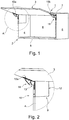
- Fig. 1
- eine perspektivische Ansicht auf ein erfindungsgemäßes Möbel mit einer erfindungsgemäßen Vorrichtung zur Bewegung eines geöffnet dargestellten Möbelteils,
- Fig. 2
- den in
Fig. 1 umrandeten Bereich A in vergrößerter Darstellung, - Fig. 3
- eine Seitenansicht auf Führungsmittel der Vorrichtung,
- Fig. 4
- eine Seitenansicht auf die Führungsmittel aus
Fig. 3 , wobei Teile der Führungsmittel transparent dargestellt sind, - Fig. 5
- eine Detailansicht B der Führungsmittel gemäß
Fig. 4 , - Fig. 6
- eine Draufsicht auf einen erfindungsgemäßen Gelenkhebel,
- Fig. 7
- eine Detailansicht eines Details C des Gelenkhebels gemäß
Fig. 6 , - Fig. 8
- eine Seitenansicht des Gelenkhebels gemäß
Fig. 6 , - Fig. 9
- eine perspektivische Ansicht eines weiteren Gelenkhebels,
- Fig. 10
- eine Seitenansicht auf Führungsmittel mit einer weiteren Ausbildung von Gelenkhebeln, wobei Teile der Gelenkhebel transparent dargestellt sind,
- Fig. 11
- eine Detailansicht D eines Gelenkhebels der Führungsmittel gemäß
Fig. 10 - Fig. 12
- eine Seitenansicht auf den Gelenkhebel der Führungsmittel gemäß den
Figuren 10 und 11 , - Fig. 13
- eine Draufsicht auf den Gelenkhebel gemäß
Fig. 12 , - Fig. 14
- eine Detailansicht E des Gelenkhebels gemäß
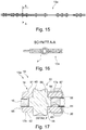
Fig. 13 , - Fig. 15
- eine Draufsicht auf Führungsmittel in einer weiteren Ausbildung,
- Fig. 16
- eine Schnittansicht der Führungsmittel gemäß
Fig. 15 , - Fig. 17
- eine Detailansicht F des Schnitts gemäß
Fig. 16 . -
Fig. 1 zeigt perspektivisch ein erfindungsgemäßes Möbel bzw. einen Oberschrank 1 mit einem kastenförmigen Möbelkorpus 2 und einem daran aufgenommenen Möbelteil, das als eine plattenartige Oberklappe 3 ausgebildet ist, welche in einer Offenstellung relativ zum Möbelkorpus 2 gezeigt ist. - Der Möbelkorpus 2 umfasst zwei gegenüberliegende, aufrechte Seitenwände 4 und 5, die unten mit einem Unterboden 6 und oben mit einem Oberboden 7 verbunden sind. Rückseitig ist der Möbelkorpus 2 von einer Rückwand 8 verschlossen.
- Zur Bewegung der Oberklappe 3 um eine horizontale Schwenkachse relativ zum Möbelkorpus 2 aus der in
Fig. 1 gezeigten Offenstellung in eine zum Möbelkorpus 2 frontseitig heranbewegte Schließstellung (nicht gezeigt) ist eine erfindungsgemäße Bewegungsvorrichtung vorhanden, die als Oberklappenbeschlag 9 ausgestaltet ist. Der Oberklappenbeschlag 9 weist an der Seitenwand 4 eine erste Beschlageinheit 10 und an der Seitenwand 5 eine zweite Beschlageinheit 11 auf, die gleichartig aber zur funktionsrichtigen Anordnung an der jeweiligen Seitenwand 4 bzw. 5 seitenbezogen aufgebaut sind. - Jede Beschlageinheit 10 und 11 umfasst eine Basiseinheit 12, Führungsmittel 13 mit Gelenkhebeln und eine Montageeinheit in Form eine Montageplatte 15a, 15b. Über mehrere gelenkig gelagerte Gelenkhebel, welche als Schwenk- oder Hebelarme einer Schwenkarm-Anordnung 14 vorhanden sind, ist die Basiseinheit 12 mit der Montageplatte 15a, 15b verbunden, welche fest an einer Innenseite der Oberklappe 3 z.B. versenkt in einer Materialausnehmung befestigt ist.
- In
Figur 3 und 4 ist eine Seitenansicht von Führungsmitteln 13a in einer ersten Ausbildungsvariante dargestellt, wobei inFigur 4 Teile der Führungsmittel 13a transparent gehalten sind. - In
Figur 5 ist eine Detailansicht B der Führungsmittel 13a dargestellt. InFigur 5 gezeigt ist ein Gelenkhebel 16 und ein Hebelarm 17a eines sandwichartig ausgebildeten weiteren Gelenkhebels 18. Der Gelenkhebel 18 umfasst zwei Hebelarme 17a, 17b. Der Gelenkhebel 16 umfasst einen einzigen Hebelarm und ist im angeordneten Zustand zwischen den Hebelarmen 17a, 17b des Gelenkhebels 18 vorhanden. Am Gelenkhebel 16 ist an einem Anbindungsbereich 19 ein Anbindungsmittel in Form einer Öffnung 20 ausgebildet. Um die Öffnung 20 erstreckt sich auf einer ersten Seite 21 des Gelenkhebels 16 in radialer Richtung eine erste Prägung 29 in Form von Erhebungen 22 bis 24 und Vertiefungen 25 bis 27. Die Erhebungen 22 - 24 und Vertiefungen 25 - 27 sind vorteilhafterweise kreissegmentartig vorhanden. Die Erhebungen 22 - 24 und Vertiefungen 25 - 27 sind vorteilhafterweise in der Bildebene versetzt zu einer verbleibenden Oberfläche 28 der ersten Seite 21 ausgebildet. In der Öffnung 20 ist außerdem ein Nietorgan 30 gezeigt. Vorteilhafterweise umfasst der Gelenkhebel 16 zwei Anbindungsbereiche 19, 31. - In der Detailansicht C (
Figur 7 ) des Gelenkhebels 16 sind die erste Prägung 29 und eine zweite Prägung 32 gezeigt. Die Prägung 32 befindet sich am Anbindungsbereich 19 auf einer zweiten Seite 33 gegenüberliegend zur ersten Prägung 29, wobei Teile der zweiten Prägung 32 erhaben oder vertieft zu einer verbleibenden Oberfläche 34 der zweiten Seite 33 des Gelenkhebels 16 ausgebildet sind. Eine Vertiefung 26 der ersten Prägung 29 ist vorteilhafterweise gegenüberliegend zu einer Erhebung 35 der zweiten Prägung 32 ausgebildet. Eine Dicke oder Breite d des Gelenkhebels 16 ist vorteilhafterweise durch einen Abstand der verbleibenden Oberfläche 28 der ersten Seite 21 zur verbleibenden Oberfläche 34 der zweiten Seite 33 des Gelenkhebels 16 gebildet. Ein Abstand einer Oberfläche 41 der Erhebung 35 der zweiten Prägung 32 zu einer Oberfläche 42 der Vertiefung 26 der ersten Prägung 29 oder umgekehrt ist vorteilhafterweise gleich der Breite d des Gelenkhebels 16. - In
Figur 9 ist ein Hebelarm 36 eines weiteren Gelenkhebels 37 der Führungsmittel 13a dargestellt. Der Hebelarm 36 umfasst vorteilhafterweise drei Anbindungsbereiche 38 - 40. Die Gelenkhebel 18, 37, welche insbesondere einen einzigen Hebelarm aufweisen sind im angeordneten Zustand an den Führungsmitteln 13a vorteilhafterweise in einer Ebene nebeneinander angeordnet (sieheFigur 4 ). - Die
Figuren 10 bis 14 zeigen Führungsmittel 13b mit einer weiteren Variante von Prägungen. In denFiguren 10 bis 14 ist ein Gelenkhebel 43 mit zwei Anbindungsbereichen 44, 45 gezeigt. Die Prägungen 50, 51 der Anbindungsbereiche 44, 45 weisen kreisförmige Erhebungen 47, 49 und Vertiefungen 46, 48 auf. Die Erhebung und Vertiefung einer Prägung 50, 51 sind in radialer Richtung um eine Öffnung 52, 53 eines Anbindungsbereichs 44, 45 gesehen abwechselnd verlaufend ausgebildet. Ein Anbindungsbereich 44 umfasst vorteilhafterweise zwei Prägungen 50, 54, wobei eine erste Prägung 50 auf einer ersten Seite 55 und eine zweite Prägung 54 auf einer zweiten Seite 56 des Gelenkhebels 43 sich gegenüberliegend angeordnet sind. In der Variante gemäß denFiguren 10 bis 14 besitzt eine Erhebung 49 der ersten Prägung 50 zu einer Erhebung 57 der zweiten Prägung 54 des Anbindungsbereichs 44 verschiedene Kreisflächen. Beispielsweise ist ein Außendurchmesser D1 der Erhebung 57 der zweiten Prägung 54 gleich einem Innendurchmesser der Erhebung 49 der ersten Prägung 50. Ein Außendurchmesser D2 der Erhebung 49 der ersten Prägung 50 ist beispielsweise größer als der Außendurchmesser D1 der Erhebung 57 der zweiten Prägungen 54. Entsprechend Umgekehrtes gilt beispielsweise für die Vertiefungen der Prägungen 50, 54. - In
Figur 17 ist eine Schnittansicht durch den Anbindungsbereich 19 der Führungsmittel 13a gezeigt. Gezeigt ist der Gelenkhebel 16, die Hebelarme 17a, 17b des Gelenkhebels 18 und das Nietorgan 30. Das Nietorgan 30 besteht aus drei zylinderförmigen Elementen 58 - 60, welche einstückig miteinander ausgebildet sind. Das mittlere Element 59 des Nietorgans 30 besitzt einen größeren Außendurchmesser als die beiden äußeren Elemente 58, 59. Das Nietorgan 30 ist vorteilhafterweise derart ausgebildet, dass es mit dem mittleren Element 59 vorteilhafterweise passgenau in die Öffnung 20 des Gelenkhebels 16 einsetzbar ist. - Stirnseiten des mittleren Elements 59 bilden vorteilhafterweise Anlageflächen 63, 64 für innere Oberflächen 65, 66 der Hebelarme 17a, 17b des Gelenkhebels 18. Im angeordneten Zustand sind die Hebelarme 17a, 17b vorteilhafterweise beweglich an den Anlageflächen 63, 64 des mittleren Elements 59 gelagert. Außerdem sind die inneren Oberflächen 65, 66 der Hebelarme 17a, 17b des Gelenkhebels 18 bevorzugterweise an Anlageflächen 67, 68 von Erhebungen der Prägungen 29, 32 des Gelenkhebels 16 im angeordneten Zustand beweglich gelagert. Die Erhebungen der Prägungen 29, 32 des Gelenkhebels 16 bilden mit den Anlageflächen 63, 64 des Nietorgans 30 vorteilhafterweise Anlageebenen oder Lagerebenen für die inneren Oberflächen 65, 66 der Hebelarme 17a, 17b des Gelenkhebels 18.
- Im angeordneten Zustand erstrecken sich die äußeren Elemente 58, 59 vorteilhafterweise über eine äußere Oberfläche 61, 62 der Hebelarme 17a, 17b. Hierdurch sind die äußeren Elemente 58, 59 des Nietorgans 30 z.B. mittels eines Taumlers taumelbar, insbesondere verformbar, sodass das Nietorgan 30 die Gelenkhebel 16, 18 nach dem Taumeln oder Verformen miteinander insbesondere beweglich und unlösbar verbindet.
Bezugszeichenliste 1 Oberschrank 29 Prägung 2 Möbelkorpus 30 Nietorgan 3 Oberklappe 31 Anbindungsbereich 4 Seitenwand 33 Seite 5 Seitenwand 32 Prägung 6 Unterboden 34 Oberfläche 7 Oberboden 35 Erhebung 8 Rückwand 36 Hebelarm 9 Oberklappenbeschlag 37 Gelenkhebel 10 Beschlageinheit 38 - 40 Anbindungsbereich 11 Beschlageinheit 41 Oberfläche 12 Basiseinheit 42 Oberfläche 13 Führungsmittel 43 Gelenkhebel 13a, 13b Führungsmittel 44, 45 Anbindungsbereich 14 Schwenkarm-Anordnung 46, 48 Vertiefung 47, 49 Erhebung 15a, 15b Montageplatte 50, 51 Prägung 16 Gelenkhebel 52, 53 Öffnung 17a, 17b Hebelarm 54 Prägung 18 Gelenkhebel 55, 56 Seite 19 Anbindungsbereich 57 Erhebung 20 Öffnung 58 - 60 Element 21 Seite 61, 62 Oberfläche 22 - 24 Erhebung 63, 64 Anlagefläche 25 - 27 Vertiefung 65, 66 Oberfläche 28 Oberfläche 67, 68 Anlagefläche
Claims (12)
- Gelenkhebel (16) für eine Vorrichtung (9) zur Bewegung eines an einem Möbelkorpus (2) eines Möbels (1) aufgenommenen Möbelteils (3),
dadurch gekennzeichnet, dass
der Gelenkhebel (16) ein Distanzorgan in Form einer ersten und einer zweiten Prägung (29, 32) aufweist, wobei die erste Prägung (29) auf einer ersten Seite (21) des ersten Gelenkhebels (16) und die zweite Prägung (32) auf einer zweiten Seite (33) des ersten Gelenkhebels (16) vorhanden ist, wobei die erste und die zweite Seite (21, 33) des ersten Gelenkhebels (16) sich gegenüberliegend und voneinander beabstandet vorhanden sind, wobei die erste und die zweite Prägung (29, 32) gegenüberliegend vorhanden sind, wobei die erste Prägung (29) in azimutaler und/oder radialer Richtung um eine Mitte eine Erhebung (22 - 24) und eine Vertiefung (25 - 27) relativ zu einer verbleibenden Fläche (28) der ersten Seite aufweist (21) und
die zweite Prägung (32) in azimutaler und/oder radialer Richtung um eine Mitte eine Erhebung (35) und eine Vertiefung relativ zu einer verbleibenden Fläche (34) der zweiten Seite (33) aufweist. - Gelenkhebel (16) für eine Vorrichtung (9) zur Bewegung eines an einem Möbelkorpus (2) eines Möbels (1) aufgenommenen Möbelteils (3) nach dem Anspruch 1,
dadurch gekennzeichnet, dass
die erste und/oder die zweite Prägung (29, 32) mehrere Erhebungen und/oder mehrere Vertiefungen umfasst und diese alternierend ausgebildet sind. - Gelenkhebel (16) für eine Vorrichtung (9) zur Bewegung eines an einem Möbelkorpus (2) eines Möbels (1) aufgenommenen Möbelteils (3) nach einem der vorangegangenen Ansprüche,
dadurch gekennzeichnet, dass
der Gelenkhebel (16) ein Anbindungsmittel in Form einer durchgehende Öffnung (20) aufweist, welche sich ausgehend von der ersten Seite (21) des Gelenkhebels (16) bis zur gegenüberliegenden zweiten Seite (33) des Gelenkhebels (16) erstreckt und wobei die erste und/oder die zweite Prägung (29, 32) sich um die Öffnung (20) erstreckend ausgebildet ist. - Gelenkhebel (16) für eine Vorrichtung (9) zur Bewegung eines an einem Möbelkorpus (2) eines Möbels (1) aufgenommenen Möbelteils (3) nach einem der vorangegangenen Ansprüche,
dadurch gekennzeichnet, dass
der Gelenkhebel (16) zwei, drei oder mehr Distanzorgane (19, 31) aufweist, welche voneinander beabstandet am Gelenkhebel (16) ausgebildet sind. - Gelenkhebel (16) für eine Vorrichtung (9) zur Bewegung eines an einem Möbelkorpus (2) eines Möbels (1) aufgenommenen Möbelteils (3) nach einem der vorangegangenen Ansprüche,
dadurch gekennzeichnet, dass
die erste Prägung und/oder die zweite Prägung (29, 32) eine Anlagefläche (35) aufweist. - Gelenkhebel (16) für eine Vorrichtung (9) zur Bewegung eines an einem Möbelkorpus (2) eines Möbels (1) aufgenommenen Möbelteils (3) nach einem der vorangegangenen Ansprüche,
dadurch gekennzeichnet, dass
die Erhebung (22 - 24) der ersten Prägung (29) und/oder die Erhebung (35) der zweiten Prägung (32) die Anlagefläche aufweist. - Vorrichtung (9) zur Bewegung eines an einem Möbelkorpus (2) eines Möbels (1) aufgenommenen Möbelteils (3), wobei die Vorrichtung (9) Führungsmittel (13) aufweist, wobei bei montierter Vorrichtung (9) am Möbel (1) das Möbelteil (3) mit den Führungsmitteln (13) aus einer Schließposition relativ zum Möbelkorpus (2) in eine Offenposition relativ zum Möbelkorpus (2) und zurück bewegbar ist, wobei das Möbelteil (3) in der Schließposition eine an eine Frontseite (4b) des Möbelkorpus (2) heranbewegte Position einnimmt, wobei ein Führungsmittel (13) als ein erster Gelenkhebel (16) ausgebildet ist und ein weiteres Führungsmittel als ein zweiter Gelenkhebel (18) ausgebildet ist, wobei der zweite Gelenkhebel (18) sandwichartig mit wenigstens zwei Hebelarmen (17a, 17b) ausgebildet ist, sodass der erste Gelenkhebel (16) zwischen den zwei Hebelarmen (17a, 17b) des zweiten Gelenkhebels (18) beweglich aufgenommen ist, wobei der erste und der zweite Gelenkhebel (16, 18) an einem Anbindungsbereich (19) durch Anbindungsmittel gelenkig miteinander verbunden sind,
dadurch gekennzeichnet, dass
der erste Gelenkhebel (16) als ein Gelenkhebel nach einem der vorangegangenen Ansprüche ausgebildet ist, und wobei die Prägungen (29, 32) des ersten Gelenkhebels (16) zwischen den Hebelarmen (17a, 17b) des zweiten Gelenkhebels (18) angeordnet sind. - Vorrichtung (9) zur Bewegung eines an einem Möbelkorpus (2) eines Möbels (1) aufgenommenen Möbelteils (3) nach dem Oberbegriff des Anspruchs 7, insbesondere nach Anspruch 7,
dadurch gekennzeichnet, dass
die Vorrichtung (9) ein Nietorgan (30) umfasst, wobei das Nietorgan (30) eine Zylinderform aufweist, welche in einem mittleren Bereich (59) einen größeren Durchmesser besitzt als in einem Bereich eines ersten Endes des Nietorgans (30) und als in einem Bereich eines zweiten Endes des Nietorgans (30) . - Vorrichtung (9) zur Bewegung eines an einem Möbelkorpus (2) eines Möbels (1) aufgenommenen Möbelteils (3) nach dem vorangegangenen Anspruch 8,
dadurch gekennzeichnet, dass
das Nietorgan (30) als ein Vollniet ausgebildet ist. - Vorrichtung (9) zur Bewegung eines an einem Möbelkorpus (2) eines Möbels (1) aufgenommenen Möbelteils (3) nach dem vorangegangenen Anspruch 7 bis 9,
dadurch gekennzeichnet, dass
das Nietorgan (30) derart vorhanden ist, dass im angeordneten Zustand des Nietorgans (30) an der Öffnung (20) des ersten Gelenkhebels (16) das Nietorgan (30) die Öffnung (20) durchgreift und mit seinem mittleren Bereich (59) im Bereich der Öffnung (20) angeordnet ist, wobei das Nietorgan (30) sich mit dem ersten Ende (58) über die erste Seite (21, 28) des ersten Gelenkhebels (16) und mit dem zweiten Ende (60) über die zweite Seite (33, 34) des ersten Gelenkhebels (16) hinaus erstreckt, wobei der mittlere Bereich (59) des Nietorgans (30) entlang einer Zylinderachse des Nietorgans (30) länger ist, als eine Breite des ersten Gelenkhebels (16), wobei die Breite sich von der verbleibenden Fläche (258) der ersten Seite (21) bis zur verbleibenden Fläche (34) der zweiten Seite (33) des ersten Gelenkhebels (16) erstreckt, sodass eine Stirnseite (63, 64) des mittleren Bereichs (59) ein Anlageorgan (65, 66) für den zweiten Gelenkhebel (18) bildet. - Vorrichtung (9) zur Bewegung eines an einem Möbelkorpus (2) eines Möbels (1) aufgenommenen Möbelteils (3) nach dem vorangegangenen Anspruch 7 bis 10,
dadurch gekennzeichnet, dass
das Nietorgan (30) derart vorhanden ist, dass sich der mittlere Bereich (59) des Nietorgans (30) entlang einer Zylinderachse des Nietorgans (30) im angeordneten Zustand von einer Anlagefläche (68) einer Erhebung der ersten Prägung (28) bis zu einer Anlagefläche (67) einer Erhebung der zweiten Prägung (32) erstreckt. - Möbel (1) mit einem Gelenkhebel (16) nach einem der vorangegangenen Ansprüche 1 bis 6 und/oder einer Vorrichtung (9) nach einem der vorangegangenen Ansprüche 7 bis 11.
Applications Claiming Priority (1)
| Application Number | Priority Date | Filing Date | Title |
|---|---|---|---|
| DE202018102086.2U DE202018102086U1 (de) | 2018-04-17 | 2018-04-17 | Gelenkhebel für eine Vorrichtung zur Bewegung eines an einem Möbelkorpus eines Möbels aufgenommenen Möbelteils |
Publications (2)
| Publication Number | Publication Date |
|---|---|
| EP3564471A1 true EP3564471A1 (de) | 2019-11-06 |
| EP3564471B1 EP3564471B1 (de) | 2023-11-01 |
Family
ID=66105017
Family Applications (1)
| Application Number | Title | Priority Date | Filing Date |
|---|---|---|---|
| EP19168329.1A Active EP3564471B1 (de) | 2018-04-17 | 2019-04-10 | Gelenkhebel für eine vorrichtung zur bewegung eines an einem möbelkorpus eines möbels aufgenommenen möbelteils |
Country Status (6)
| Country | Link |
|---|---|
| US (1) | US10968670B2 (de) |
| EP (1) | EP3564471B1 (de) |
| JP (1) | JP6872578B2 (de) |
| CN (1) | CN110439919B (de) |
| DE (1) | DE202018102086U1 (de) |
| ES (1) | ES2969564T3 (de) |
Families Citing this family (3)
| Publication number | Priority date | Publication date | Assignee | Title |
|---|---|---|---|---|
| DE102019100188A1 (de) * | 2019-01-07 | 2020-07-09 | Grass Gmbh | Vorrichtung zum Bewegen einer Möbelklappe und Möbel |
| AT522458B1 (de) * | 2019-05-17 | 2020-11-15 | Blum Gmbh Julius | Möbelbeschlag |
| AT17215U1 (de) * | 2020-03-03 | 2021-09-15 | Blum Gmbh Julius | Möbelbeschlag |
Citations (3)
| Publication number | Priority date | Publication date | Assignee | Title |
|---|---|---|---|---|
| GB2092220A (en) * | 1981-02-02 | 1982-08-11 | Shaw Arthur Mfg Ltd | Improvements in stays for windows |
| EP0158604A2 (de) * | 1984-02-29 | 1985-10-16 | Società "OMAS" - S.r.l. | Unsichtbares Scharnier mit vereinfachtem Mechanismus und elastischer Befestigungsdübel |
| GB2335702A (en) * | 1995-11-25 | 1999-09-29 | Dgs Hardware Ltd | A window stay with ribbed links |
Family Cites Families (27)
| Publication number | Priority date | Publication date | Assignee | Title |
|---|---|---|---|---|
| US2122034A (en) * | 1937-03-19 | 1938-06-28 | Jackle Johann | Hinge |
| JPS5157366A (en) * | 1974-11-13 | 1976-05-19 | Tokyo Shibaura Electric Co | Shafutono kashimehoho |
| DE2834529A1 (de) * | 1978-08-07 | 1980-02-21 | Keiper Automobiltechnik Gmbh | Gelenkbeschlag fuer sitze mit verstellbarer rueckenlehne, insbesondere kraftfahrzeugsitze |
| DE3133657A1 (de) * | 1980-09-04 | 1982-06-24 | Arthur Shaw Mfg. Ltd., Willenhall, West Midlands | "reibungsstuetze fuer fenster o.dgl." |
| IT1180561B (it) * | 1984-02-29 | 1987-09-23 | Marco Grilli | Guscio elastico per ceniere a scomparsa |
| US5195215A (en) * | 1991-08-13 | 1993-03-23 | Ran Enterprises, Inc. | Hinge arm |
| JP3330982B2 (ja) * | 1992-08-21 | 2002-10-07 | 東北パイオニア株式会社 | リベッティング結合部のかしめ方法 |
| JPH07212207A (ja) * | 1994-01-24 | 1995-08-11 | Fuji Electric Co Ltd | 方形波定電流発生回路 |
| EP1068986B1 (de) * | 1995-06-23 | 2003-10-22 | Fuji Kiko Co., Ltd. | Verstellbarer Drehgelenkbeschlag für neigungsverstellbare Sitze |
| JPH1177193A (ja) * | 1997-08-28 | 1999-03-23 | Fuji Kiko Co Ltd | リンク回転連結構造及びその製造方法 |
| US6061870A (en) * | 1998-01-07 | 2000-05-16 | The Burton Corporation | Bushing system |
| DE20003289U1 (de) * | 2000-02-23 | 2001-07-05 | Mepla-Werke Lautenschläger GmbH & Co. KG, 64354 Reinheim | Dreh-Gelenkverbindung von Bauteilen aus dünnem plattenförmigem Material |
| AU2002303134A1 (en) * | 2001-03-16 | 2002-10-03 | Creare Inc. | Lightweight direct methanol fuel cell and supporting systems |
| TW536575B (en) * | 2001-05-03 | 2003-06-11 | Salice Arturo Spa | An apparatus for securing a part to an extruded section |
| DE10145856B4 (de) * | 2001-09-17 | 2005-09-08 | Huwil-Werke Gmbh Möbelschloss- Und Beschlagfabriken | Faltdeckel |
| US6892784B2 (en) * | 2003-03-06 | 2005-05-17 | Paul A. Maas | Stabilized portable room divider |
| JP4188116B2 (ja) * | 2003-03-18 | 2008-11-26 | 山下ゴム株式会社 | 防振装置 |
| WO2007134436A1 (en) * | 2006-05-18 | 2007-11-29 | Sur-Stud Structural Technology Inc. | Light steel structural members |
| DE102008005463A1 (de) * | 2008-01-21 | 2009-07-23 | Huwil-Werke Gmbh Möbelschloss- Und Beschlagfabriken | Halteelement zum Verstellen eines Deckels eines Möbels |
| CA2711999A1 (en) * | 2008-03-11 | 2009-09-17 | Magna Seating Inc. | Chuckless bushingless joint design |
| JP5415490B2 (ja) * | 2011-07-29 | 2014-02-12 | スガツネ工業株式会社 | 支持部材付き扉開閉装置及び扉開閉装置用の支持部材 |
| US9944116B1 (en) * | 2013-03-15 | 2018-04-17 | Phoenix U.S.A., Inc. | Wheel trim alignment system with an embossment |
| AT515216B1 (de) * | 2014-05-02 | 2015-07-15 | Blum Gmbh Julius | Stellantrieb für Möbelklappen |
| US20160025165A1 (en) * | 2014-07-24 | 2016-01-28 | Bendix Spicer Foundation Brake Llc | Brake Disc Mounting Arrangement |
| US9963291B2 (en) * | 2016-04-06 | 2018-05-08 | Altria Client Services Llc | Multicompartment capsules of a beverage forming apparatus and methods of making thereof |
| US9936624B2 (en) * | 2016-09-08 | 2018-04-10 | Kuhn Krause, Inc. | Lift assist system for agricultural tools |
| NO20162055A1 (en) * | 2016-12-23 | 2017-12-18 | Sapeg As | Downhole stuck object removal tool |
-
2018
- 2018-04-17 DE DE202018102086.2U patent/DE202018102086U1/de active Active
-
2019
- 2019-04-10 EP EP19168329.1A patent/EP3564471B1/de active Active
- 2019-04-10 ES ES19168329T patent/ES2969564T3/es active Active
- 2019-04-11 US US16/381,345 patent/US10968670B2/en active Active
- 2019-04-17 JP JP2019078573A patent/JP6872578B2/ja active Active
- 2019-04-17 CN CN201910308028.4A patent/CN110439919B/zh active Active
Patent Citations (3)
| Publication number | Priority date | Publication date | Assignee | Title |
|---|---|---|---|---|
| GB2092220A (en) * | 1981-02-02 | 1982-08-11 | Shaw Arthur Mfg Ltd | Improvements in stays for windows |
| EP0158604A2 (de) * | 1984-02-29 | 1985-10-16 | Società "OMAS" - S.r.l. | Unsichtbares Scharnier mit vereinfachtem Mechanismus und elastischer Befestigungsdübel |
| GB2335702A (en) * | 1995-11-25 | 1999-09-29 | Dgs Hardware Ltd | A window stay with ribbed links |
Also Published As
| Publication number | Publication date |
|---|---|
| EP3564471B1 (de) | 2023-11-01 |
| US20190316395A1 (en) | 2019-10-17 |
| CN110439919B (zh) | 2021-10-08 |
| JP6872578B2 (ja) | 2021-05-19 |
| JP2019218843A (ja) | 2019-12-26 |
| ES2969564T3 (es) | 2024-05-21 |
| CN110439919A (zh) | 2019-11-12 |
| DE202018102086U1 (de) | 2019-07-18 |
| US10968670B2 (en) | 2021-04-06 |
Similar Documents
| Publication | Publication Date | Title |
|---|---|---|
| EP2739445B1 (de) | Backenpaar zum ausstanzen von löchern | |
| DE102011108976B4 (de) | Verfahren zur Herstellung einer Lageranordnung und Beschlag für einen Fahrzeugsitz mit einer hiernach hergestellten Lageranordnung | |
| EP2830910B1 (de) | Fahrzeugsitz | |
| EP2668085B1 (de) | Feststelleinrichtung zum feststellen einer lenkspindellagereinheit | |
| EP3556978A1 (de) | Vorrichtung zur bewegung eines an einem möbelkorpus eines möbels aufgenommenen möbelteils | |
| EP3564471B1 (de) | Gelenkhebel für eine vorrichtung zur bewegung eines an einem möbelkorpus eines möbels aufgenommenen möbelteils | |
| DE102013225858B4 (de) | Verriegelungseinheit für einen Fahrzeugsitz und Fahrzeugsitz | |
| DE102008017019A1 (de) | Gelenkbeschlag für Kraftfahrzeugsitze und mit einer Ronde | |
| EP2855197A1 (de) | Verriegelungseinheit für einen fahrzeugsitz | |
| EP2383165A2 (de) | Spannteil für eine in einer verstellbaren Lenksäule für ein Kraftfahrzeug integrierte Spannvorrichtung | |
| EP3057826B1 (de) | Fahrzeugsitz, insbesondere kraftfahrzeugsitz | |
| DE102012223469A1 (de) | Verbindungselement und Herstellungsverfahren für ein Verbindungselement | |
| EP2495116B1 (de) | Stütze zur schwenkbaren Lagerung des Achslenkers einer Fahrzeugachse | |
| EP3786405B1 (de) | Möbelantrieb zum bewegen eines bewegbar gelagerten möbelteiles | |
| WO2010092062A2 (de) | Scheibenbremsbelagträgerplatte | |
| DE19519447C3 (de) | Vorrichtung zur Befestigung eines Radiators auf einer Unterlage | |
| DE69017214T2 (de) | Verfahren und vorrichtung zum ausgleichen der verformungen des rahmens einer exzenterpresse. | |
| EP3049278B1 (de) | Verriegelungseinheit für einen fahrzeugsitz und fahrzeugsitz | |
| DE102011110732A1 (de) | Blechumformwerkzeug mit Blechdistanzhalter | |
| EP3335929B1 (de) | Fahrzeugsitz mit federung | |
| DE3915336A1 (de) | Getriebeanordnung und verfahren zu ihrer herstellung | |
| DE102010054684B4 (de) | Lager eines Fahrzeugsitzes | |
| EP4575111A1 (de) | Betätigungsvorrichtung zum auslösen einer spülung eines sanitärartikels | |
| DE202023101471U1 (de) | Adaptive Form | |
| WO2006092124A1 (de) | Anlenkung für eine türhaltestange |
Legal Events
| Date | Code | Title | Description |
|---|---|---|---|
| PUAI | Public reference made under article 153(3) epc to a published international application that has entered the european phase |
Free format text: ORIGINAL CODE: 0009012 |
|
| STAA | Information on the status of an ep patent application or granted ep patent |
Free format text: STATUS: THE APPLICATION HAS BEEN PUBLISHED |
|
| AK | Designated contracting states |
Kind code of ref document: A1 Designated state(s): AL AT BE BG CH CY CZ DE DK EE ES FI FR GB GR HR HU IE IS IT LI LT LU LV MC MK MT NL NO PL PT RO RS SE SI SK SM TR |
|
| AX | Request for extension of the european patent |
Extension state: BA ME |
|
| STAA | Information on the status of an ep patent application or granted ep patent |
Free format text: STATUS: REQUEST FOR EXAMINATION WAS MADE |
|
| 17P | Request for examination filed |
Effective date: 20200430 |
|
| RBV | Designated contracting states (corrected) |
Designated state(s): AL AT BE BG CH CY CZ DE DK EE ES FI FR GB GR HR HU IE IS IT LI LT LU LV MC MK MT NL NO PL PT RO RS SE SI SK SM TR |
|
| STAA | Information on the status of an ep patent application or granted ep patent |
Free format text: STATUS: EXAMINATION IS IN PROGRESS |
|
| 17Q | First examination report despatched |
Effective date: 20220103 |
|
| REG | Reference to a national code |
Ref country code: DE Ref legal event code: R079 Free format text: PREVIOUS MAIN CLASS: E05D0003060000 Ipc: E05D0015400000 Ref document number: 502019009796 Country of ref document: DE |
|
| RIC1 | Information provided on ipc code assigned before grant |
Ipc: E05D 3/16 20060101ALI20230322BHEP Ipc: E05D 3/06 20060101ALI20230322BHEP Ipc: E05D 15/40 20060101AFI20230322BHEP |
|
| GRAP | Despatch of communication of intention to grant a patent |
Free format text: ORIGINAL CODE: EPIDOSNIGR1 |
|
| STAA | Information on the status of an ep patent application or granted ep patent |
Free format text: STATUS: GRANT OF PATENT IS INTENDED |
|
| INTG | Intention to grant announced |
Effective date: 20230522 |
|
| GRAS | Grant fee paid |
Free format text: ORIGINAL CODE: EPIDOSNIGR3 |
|
| GRAA | (expected) grant |
Free format text: ORIGINAL CODE: 0009210 |
|
| STAA | Information on the status of an ep patent application or granted ep patent |
Free format text: STATUS: THE PATENT HAS BEEN GRANTED |
|
| AK | Designated contracting states |
Kind code of ref document: B1 Designated state(s): AL AT BE BG CH CY CZ DE DK EE ES FI FR GB GR HR HU IE IS IT LI LT LU LV MC MK MT NL NO PL PT RO RS SE SI SK SM TR |
|
| REG | Reference to a national code |
Ref country code: GB Ref legal event code: FG4D Free format text: NOT ENGLISH |
|
| REG | Reference to a national code |
Ref country code: CH Ref legal event code: EP |
|
| REG | Reference to a national code |
Ref country code: IE Ref legal event code: FG4D Free format text: LANGUAGE OF EP DOCUMENT: GERMAN |
|
| REG | Reference to a national code |
Ref country code: DE Ref legal event code: R096 Ref document number: 502019009796 Country of ref document: DE |
|
| REG | Reference to a national code |
Ref country code: LT Ref legal event code: MG9D |
|
| REG | Reference to a national code |
Ref country code: NL Ref legal event code: MP Effective date: 20231101 |
|
| PG25 | Lapsed in a contracting state [announced via postgrant information from national office to epo] |
Ref country code: GR Free format text: LAPSE BECAUSE OF FAILURE TO SUBMIT A TRANSLATION OF THE DESCRIPTION OR TO PAY THE FEE WITHIN THE PRESCRIBED TIME-LIMIT Effective date: 20240202 |
|
| PG25 | Lapsed in a contracting state [announced via postgrant information from national office to epo] |
Ref country code: IS Free format text: LAPSE BECAUSE OF FAILURE TO SUBMIT A TRANSLATION OF THE DESCRIPTION OR TO PAY THE FEE WITHIN THE PRESCRIBED TIME-LIMIT Effective date: 20240301 |
|
| PG25 | Lapsed in a contracting state [announced via postgrant information from national office to epo] |
Ref country code: LT Free format text: LAPSE BECAUSE OF FAILURE TO SUBMIT A TRANSLATION OF THE DESCRIPTION OR TO PAY THE FEE WITHIN THE PRESCRIBED TIME-LIMIT Effective date: 20231101 |
|
| PG25 | Lapsed in a contracting state [announced via postgrant information from national office to epo] |
Ref country code: NL Free format text: LAPSE BECAUSE OF FAILURE TO SUBMIT A TRANSLATION OF THE DESCRIPTION OR TO PAY THE FEE WITHIN THE PRESCRIBED TIME-LIMIT Effective date: 20231101 |
|
| PG25 | Lapsed in a contracting state [announced via postgrant information from national office to epo] |
Ref country code: NL Free format text: LAPSE BECAUSE OF FAILURE TO SUBMIT A TRANSLATION OF THE DESCRIPTION OR TO PAY THE FEE WITHIN THE PRESCRIBED TIME-LIMIT Effective date: 20231101 Ref country code: LT Free format text: LAPSE BECAUSE OF FAILURE TO SUBMIT A TRANSLATION OF THE DESCRIPTION OR TO PAY THE FEE WITHIN THE PRESCRIBED TIME-LIMIT Effective date: 20231101 Ref country code: IS Free format text: LAPSE BECAUSE OF FAILURE TO SUBMIT A TRANSLATION OF THE DESCRIPTION OR TO PAY THE FEE WITHIN THE PRESCRIBED TIME-LIMIT Effective date: 20240301 Ref country code: GR Free format text: LAPSE BECAUSE OF FAILURE TO SUBMIT A TRANSLATION OF THE DESCRIPTION OR TO PAY THE FEE WITHIN THE PRESCRIBED TIME-LIMIT Effective date: 20240202 Ref country code: BG Free format text: LAPSE BECAUSE OF FAILURE TO SUBMIT A TRANSLATION OF THE DESCRIPTION OR TO PAY THE FEE WITHIN THE PRESCRIBED TIME-LIMIT Effective date: 20240201 Ref country code: PT Free format text: LAPSE BECAUSE OF FAILURE TO SUBMIT A TRANSLATION OF THE DESCRIPTION OR TO PAY THE FEE WITHIN THE PRESCRIBED TIME-LIMIT Effective date: 20240301 |
|
| REG | Reference to a national code |
Ref country code: ES Ref legal event code: FG2A Ref document number: 2969564 Country of ref document: ES Kind code of ref document: T3 Effective date: 20240521 |
|
| PG25 | Lapsed in a contracting state [announced via postgrant information from national office to epo] |
Ref country code: SE Free format text: LAPSE BECAUSE OF FAILURE TO SUBMIT A TRANSLATION OF THE DESCRIPTION OR TO PAY THE FEE WITHIN THE PRESCRIBED TIME-LIMIT Effective date: 20231101 Ref country code: RS Free format text: LAPSE BECAUSE OF FAILURE TO SUBMIT A TRANSLATION OF THE DESCRIPTION OR TO PAY THE FEE WITHIN THE PRESCRIBED TIME-LIMIT Effective date: 20231101 Ref country code: PL Free format text: LAPSE BECAUSE OF FAILURE TO SUBMIT A TRANSLATION OF THE DESCRIPTION OR TO PAY THE FEE WITHIN THE PRESCRIBED TIME-LIMIT Effective date: 20231101 Ref country code: NO Free format text: LAPSE BECAUSE OF FAILURE TO SUBMIT A TRANSLATION OF THE DESCRIPTION OR TO PAY THE FEE WITHIN THE PRESCRIBED TIME-LIMIT Effective date: 20240201 Ref country code: LV Free format text: LAPSE BECAUSE OF FAILURE TO SUBMIT A TRANSLATION OF THE DESCRIPTION OR TO PAY THE FEE WITHIN THE PRESCRIBED TIME-LIMIT Effective date: 20231101 Ref country code: HR Free format text: LAPSE BECAUSE OF FAILURE TO SUBMIT A TRANSLATION OF THE DESCRIPTION OR TO PAY THE FEE WITHIN THE PRESCRIBED TIME-LIMIT Effective date: 20231101 |
|
| PG25 | Lapsed in a contracting state [announced via postgrant information from national office to epo] |
Ref country code: DK Free format text: LAPSE BECAUSE OF FAILURE TO SUBMIT A TRANSLATION OF THE DESCRIPTION OR TO PAY THE FEE WITHIN THE PRESCRIBED TIME-LIMIT Effective date: 20231101 |
|
| PG25 | Lapsed in a contracting state [announced via postgrant information from national office to epo] |
Ref country code: CZ Free format text: LAPSE BECAUSE OF FAILURE TO SUBMIT A TRANSLATION OF THE DESCRIPTION OR TO PAY THE FEE WITHIN THE PRESCRIBED TIME-LIMIT Effective date: 20231101 |
|
| PG25 | Lapsed in a contracting state [announced via postgrant information from national office to epo] |
Ref country code: SK Free format text: LAPSE BECAUSE OF FAILURE TO SUBMIT A TRANSLATION OF THE DESCRIPTION OR TO PAY THE FEE WITHIN THE PRESCRIBED TIME-LIMIT Effective date: 20231101 |
|
| PG25 | Lapsed in a contracting state [announced via postgrant information from national office to epo] |
Ref country code: SM Free format text: LAPSE BECAUSE OF FAILURE TO SUBMIT A TRANSLATION OF THE DESCRIPTION OR TO PAY THE FEE WITHIN THE PRESCRIBED TIME-LIMIT Effective date: 20231101 Ref country code: SK Free format text: LAPSE BECAUSE OF FAILURE TO SUBMIT A TRANSLATION OF THE DESCRIPTION OR TO PAY THE FEE WITHIN THE PRESCRIBED TIME-LIMIT Effective date: 20231101 Ref country code: EE Free format text: LAPSE BECAUSE OF FAILURE TO SUBMIT A TRANSLATION OF THE DESCRIPTION OR TO PAY THE FEE WITHIN THE PRESCRIBED TIME-LIMIT Effective date: 20231101 Ref country code: DK Free format text: LAPSE BECAUSE OF FAILURE TO SUBMIT A TRANSLATION OF THE DESCRIPTION OR TO PAY THE FEE WITHIN THE PRESCRIBED TIME-LIMIT Effective date: 20231101 Ref country code: CZ Free format text: LAPSE BECAUSE OF FAILURE TO SUBMIT A TRANSLATION OF THE DESCRIPTION OR TO PAY THE FEE WITHIN THE PRESCRIBED TIME-LIMIT Effective date: 20231101 |
|
| REG | Reference to a national code |
Ref country code: DE Ref legal event code: R097 Ref document number: 502019009796 Country of ref document: DE |
|
| PLBE | No opposition filed within time limit |
Free format text: ORIGINAL CODE: 0009261 |
|
| STAA | Information on the status of an ep patent application or granted ep patent |
Free format text: STATUS: NO OPPOSITION FILED WITHIN TIME LIMIT |
|
| 26N | No opposition filed |
Effective date: 20240802 |
|
| PG25 | Lapsed in a contracting state [announced via postgrant information from national office to epo] |
Ref country code: SI Free format text: LAPSE BECAUSE OF FAILURE TO SUBMIT A TRANSLATION OF THE DESCRIPTION OR TO PAY THE FEE WITHIN THE PRESCRIBED TIME-LIMIT Effective date: 20231101 |
|
| PG25 | Lapsed in a contracting state [announced via postgrant information from national office to epo] |
Ref country code: SI Free format text: LAPSE BECAUSE OF FAILURE TO SUBMIT A TRANSLATION OF THE DESCRIPTION OR TO PAY THE FEE WITHIN THE PRESCRIBED TIME-LIMIT Effective date: 20231101 |
|
| PG25 | Lapsed in a contracting state [announced via postgrant information from national office to epo] |
Ref country code: MC Free format text: LAPSE BECAUSE OF FAILURE TO SUBMIT A TRANSLATION OF THE DESCRIPTION OR TO PAY THE FEE WITHIN THE PRESCRIBED TIME-LIMIT Effective date: 20231101 |
|
| PG25 | Lapsed in a contracting state [announced via postgrant information from national office to epo] |
Ref country code: MC Free format text: LAPSE BECAUSE OF FAILURE TO SUBMIT A TRANSLATION OF THE DESCRIPTION OR TO PAY THE FEE WITHIN THE PRESCRIBED TIME-LIMIT Effective date: 20231101 |
|
| REG | Reference to a national code |
Ref country code: CH Ref legal event code: PL |
|
| PG25 | Lapsed in a contracting state [announced via postgrant information from national office to epo] |
Ref country code: LU Free format text: LAPSE BECAUSE OF NON-PAYMENT OF DUE FEES Effective date: 20240410 |
|
| GBPC | Gb: european patent ceased through non-payment of renewal fee |
Effective date: 20240410 |
|
| REG | Reference to a national code |
Ref country code: BE Ref legal event code: MM Effective date: 20240430 |
|
| PG25 | Lapsed in a contracting state [announced via postgrant information from national office to epo] |
Ref country code: LU Free format text: LAPSE BECAUSE OF NON-PAYMENT OF DUE FEES Effective date: 20240410 |
|
| PG25 | Lapsed in a contracting state [announced via postgrant information from national office to epo] |
Ref country code: BE Free format text: LAPSE BECAUSE OF NON-PAYMENT OF DUE FEES Effective date: 20240430 |
|
| PG25 | Lapsed in a contracting state [announced via postgrant information from national office to epo] |
Ref country code: GB Free format text: LAPSE BECAUSE OF NON-PAYMENT OF DUE FEES Effective date: 20240410 |
|
| PG25 | Lapsed in a contracting state [announced via postgrant information from national office to epo] |
Ref country code: FR Free format text: LAPSE BECAUSE OF NON-PAYMENT OF DUE FEES Effective date: 20240430 |
|
| PG25 | Lapsed in a contracting state [announced via postgrant information from national office to epo] |
Ref country code: GB Free format text: LAPSE BECAUSE OF NON-PAYMENT OF DUE FEES Effective date: 20240410 Ref country code: FR Free format text: LAPSE BECAUSE OF NON-PAYMENT OF DUE FEES Effective date: 20240430 Ref country code: BE Free format text: LAPSE BECAUSE OF NON-PAYMENT OF DUE FEES Effective date: 20240430 Ref country code: CH Free format text: LAPSE BECAUSE OF NON-PAYMENT OF DUE FEES Effective date: 20240430 |
|
| REG | Reference to a national code |
Ref country code: DE Ref legal event code: R082 Ref document number: 502019009796 Country of ref document: DE Representative=s name: RAVENSPAT PATENTANWAELTE PARTNERSCHAFT MBB, DE |
|
| PG25 | Lapsed in a contracting state [announced via postgrant information from national office to epo] |
Ref country code: IE Free format text: LAPSE BECAUSE OF NON-PAYMENT OF DUE FEES Effective date: 20240410 |
|
| PGFP | Annual fee paid to national office [announced via postgrant information from national office to epo] |
Ref country code: IT Payment date: 20250306 Year of fee payment: 7 |
|
| PGFP | Annual fee paid to national office [announced via postgrant information from national office to epo] |
Ref country code: DE Payment date: 20250418 Year of fee payment: 7 |
|
| PGFP | Annual fee paid to national office [announced via postgrant information from national office to epo] |
Ref country code: ES Payment date: 20250507 Year of fee payment: 7 |
|
| PG25 | Lapsed in a contracting state [announced via postgrant information from national office to epo] |
Ref country code: RO Free format text: LAPSE BECAUSE OF FAILURE TO SUBMIT A TRANSLATION OF THE DESCRIPTION OR TO PAY THE FEE WITHIN THE PRESCRIBED TIME-LIMIT Effective date: 20231101 |
|
| PGFP | Annual fee paid to national office [announced via postgrant information from national office to epo] |
Ref country code: AT Payment date: 20250423 Year of fee payment: 7 |
|
| PGFP | Annual fee paid to national office [announced via postgrant information from national office to epo] |
Ref country code: TR Payment date: 20250408 Year of fee payment: 7 |
|
| PG25 | Lapsed in a contracting state [announced via postgrant information from national office to epo] |
Ref country code: CY Free format text: LAPSE BECAUSE OF FAILURE TO SUBMIT A TRANSLATION OF THE DESCRIPTION OR TO PAY THE FEE WITHIN THE PRESCRIBED TIME-LIMIT; INVALID AB INITIO Effective date: 20190410 |
|
| PG25 | Lapsed in a contracting state [announced via postgrant information from national office to epo] |
Ref country code: HU Free format text: LAPSE BECAUSE OF FAILURE TO SUBMIT A TRANSLATION OF THE DESCRIPTION OR TO PAY THE FEE WITHIN THE PRESCRIBED TIME-LIMIT; INVALID AB INITIO Effective date: 20190410 |
|
| PG25 | Lapsed in a contracting state [announced via postgrant information from national office to epo] |
Ref country code: FI Free format text: LAPSE BECAUSE OF FAILURE TO SUBMIT A TRANSLATION OF THE DESCRIPTION OR TO PAY THE FEE WITHIN THE PRESCRIBED TIME-LIMIT Effective date: 20231101 |