EP3564114A2 - Mécanique de retenue et de desserrage d'un dispositif de logement de câble - Google Patents
Mécanique de retenue et de desserrage d'un dispositif de logement de câble Download PDFInfo
- Publication number
- EP3564114A2 EP3564114A2 EP19000235.2A EP19000235A EP3564114A2 EP 3564114 A2 EP3564114 A2 EP 3564114A2 EP 19000235 A EP19000235 A EP 19000235A EP 3564114 A2 EP3564114 A2 EP 3564114A2
- Authority
- EP
- European Patent Office
- Prior art keywords
- cable
- actuating
- holding
- receiving device
- teeth
- Prior art date
- Legal status (The legal status is an assumption and is not a legal conclusion. Google has not performed a legal analysis and makes no representation as to the accuracy of the status listed.)
- Granted
Links
- 230000007246 mechanism Effects 0.000 title claims abstract description 67
- 230000003993 interaction Effects 0.000 description 3
- 230000007704 transition Effects 0.000 description 2
- 238000004804 winding Methods 0.000 description 2
- 238000005452 bending Methods 0.000 description 1
- 230000005540 biological transmission Effects 0.000 description 1
- 230000000694 effects Effects 0.000 description 1
- 238000000605 extraction Methods 0.000 description 1
- 238000004519 manufacturing process Methods 0.000 description 1
- 238000000034 method Methods 0.000 description 1
- 230000001960 triggered effect Effects 0.000 description 1
Images


Classifications
-
- F—MECHANICAL ENGINEERING; LIGHTING; HEATING; WEAPONS; BLASTING
- F16—ENGINEERING ELEMENTS AND UNITS; GENERAL MEASURES FOR PRODUCING AND MAINTAINING EFFECTIVE FUNCTIONING OF MACHINES OR INSTALLATIONS; THERMAL INSULATION IN GENERAL
- F16D—COUPLINGS FOR TRANSMITTING ROTATION; CLUTCHES; BRAKES
- F16D41/00—Freewheels or freewheel clutches
- F16D41/12—Freewheels or freewheel clutches with hinged pawl co-operating with teeth, cogs, or the like
-
- B—PERFORMING OPERATIONS; TRANSPORTING
- B62—LAND VEHICLES FOR TRAVELLING OTHERWISE THAN ON RAILS
- B62K—CYCLES; CYCLE FRAMES; CYCLE STEERING DEVICES; RIDER-OPERATED TERMINAL CONTROLS SPECIALLY ADAPTED FOR CYCLES; CYCLE AXLE SUSPENSIONS; CYCLE SIDE-CARS, FORECARS, OR THE LIKE
- B62K23/00—Rider-operated controls specially adapted for cycles, i.e. means for initiating control operations, e.g. levers, grips
- B62K23/02—Rider-operated controls specially adapted for cycles, i.e. means for initiating control operations, e.g. levers, grips hand actuated
- B62K23/06—Levers
-
- B—PERFORMING OPERATIONS; TRANSPORTING
- B62—LAND VEHICLES FOR TRAVELLING OTHERWISE THAN ON RAILS
- B62M—RIDER PROPULSION OF WHEELED VEHICLES OR SLEDGES; POWERED PROPULSION OF SLEDGES OR SINGLE-TRACK CYCLES; TRANSMISSIONS SPECIALLY ADAPTED FOR SUCH VEHICLES
- B62M25/00—Actuators for gearing speed-change mechanisms specially adapted for cycles
- B62M25/02—Actuators for gearing speed-change mechanisms specially adapted for cycles with mechanical transmitting systems, e.g. cables, levers
- B62M25/04—Actuators for gearing speed-change mechanisms specially adapted for cycles with mechanical transmitting systems, e.g. cables, levers hand actuated
-
- F—MECHANICAL ENGINEERING; LIGHTING; HEATING; WEAPONS; BLASTING
- F16—ENGINEERING ELEMENTS AND UNITS; GENERAL MEASURES FOR PRODUCING AND MAINTAINING EFFECTIVE FUNCTIONING OF MACHINES OR INSTALLATIONS; THERMAL INSULATION IN GENERAL
- F16C—SHAFTS; FLEXIBLE SHAFTS; ELEMENTS OR CRANKSHAFT MECHANISMS; ROTARY BODIES OTHER THAN GEARING ELEMENTS; BEARINGS
- F16C1/00—Flexible shafts; Mechanical means for transmitting movement in a flexible sheathing
- F16C1/10—Means for transmitting linear movement in a flexible sheathing, e.g. "Bowden-mechanisms"
- F16C1/22—Adjusting; Compensating length
- F16C1/223—Adjusting; Compensating length by adjusting the effective length of the flexible member
-
- Y—GENERAL TAGGING OF NEW TECHNOLOGICAL DEVELOPMENTS; GENERAL TAGGING OF CROSS-SECTIONAL TECHNOLOGIES SPANNING OVER SEVERAL SECTIONS OF THE IPC; TECHNICAL SUBJECTS COVERED BY FORMER USPC CROSS-REFERENCE ART COLLECTIONS [XRACs] AND DIGESTS
- Y10—TECHNICAL SUBJECTS COVERED BY FORMER USPC
- Y10T—TECHNICAL SUBJECTS COVERED BY FORMER US CLASSIFICATION
- Y10T74/00—Machine element or mechanism
- Y10T74/21—Elements
- Y10T74/2133—Pawls and ratchets
Definitions
- the invention relates to a holding and releasing mechanism for holding and releasing a cable receiving device such as a stepper, and a stepper comprising this holding and releasing mechanism, and a system, which in turn comprises this stepping switch.
- Stepping switch in which a holding and releasing mechanism according to the invention can be used, are used in particular for bicycles. With their help, the user of the bicycle can gradually wind the switch train and release, the actuating lever usually return to their original position after their operation.
- the term trigger switch is often used synonymously for a stepping switch.
- Stepping or triggering switches are inter alia from the patents EP 0 361 335 B1 .
- the known stepping switches each comprise a Seilaufzieh- or winding mechanism for the shift cable, as well as a mechanism for holding or releasing the shift cable.
- the present invention relates to a particularly advantageous embodiment of a holding and releasing mechanism, as well as a stepper in which this holding and releasing mechanism is used, and a switching system, in turn, this stepping switch is used.
- the holding or releasing device of EP 0 361 335 B1 includes first and second locking elements, which are mutually pivotable to intervene alternately in a toothed locking disk.
- first and second locking elements which are mutually pivotable to intervene alternately in a toothed locking disk.
- the locking element currently in engagement with the locking disk is in each case moved out of engagement with the locking disc.
- the locking disk can now turn so far until the other locking element engages in the locking teeth.
- the second locking element moves out of engagement of the locking disc, and the locking disc moves so far until it comes to re-engagement of the first locking element with her.
- a holding and releasing mechanism is known from EP 1 232 940 B2 known.
- a pivotable locking pawl engages here with its locking projection initially with a first tooth of a locking disk, whereby the locking disk is fixed. If now the locking projection is swung out of the engagement area of the first tooth, the locking disk can rotate until a tooth adjacent to the first tooth of the locking disk engages with a securing projection of the pawl pivoted simultaneously into the engagement area of the teeth.
- the locking toothed disk can continue to rotate until the locking projection of the locking pawl engages with a third tooth, which in turn is adjacent to the first tooth, and the locking toothed disk is again firmly seated.
- EP 1 366 981 B1 Another holding and releasing mechanism according to the preamble of claim 1 is known from EP 1 366 981 B1 known, in which a slidably mounted locking pawl engages alternately arranged on opposite sides of a locking tooth locking or locking teeth when a release lever is actuated.
- a holding and releasing mechanism according to the preamble of claim 1 is finally known, in which a locking pawl initially by means of a locking projection with a locking tooth is engaged. Upon actuation of a release lever, the locking pawl now pivots in such a way that the locking projection comes out of engagement with the locking tooth, whereupon a locking projection of the pawl engages with a securing tooth, during which the locking toothed disk has rotated by a certain angular amount.
- the object of the present invention to provide such a holding and releasing mechanism, which allows a particularly compact and space-saving design.
- a holding and releasing mechanism for holding and releasing a wire take-up device such as a stepper, for holding an operation cable receivable by the wire take-up device in a plurality of operating positions, comprising an operating position of maximum travel of the operating cable Cable receiving device and an operating position maximum feed of the operating cable through the cable receiving device, and for gradually releasing the operating cable in a pull-out direction, comprising a one-piece associated with the cable receiving device or rotatably connected thereto or connectable, with this rotatable about a first axis toothed pulley assembly, which at its outer periphery a plurality of teeth; an adjustable, preferably about a second axis pivotable locking pawl which engages in a first position, in particular a first pivot position befindlichem in different first rotational positions Zahnusionnan extract with a locking projection with one of the respective first rotational position, serving as a locking tooth of the plurality of
- the plurality of teeth of the toothed disc arrangement comprises a first group of teeth and a second group of teeth, wherein the teeth of the first group of teeth serve as locking teeth and are arranged in a first tooth plane orthogonal to the first axis and the teeth of the teeth serve second group of teeth as securing teeth and are arranged in a first axis orthogonal, offset from the first tooth plane second tooth plane.
- the first group of teeth may have the same number of teeth as the second group of teeth, which number may preferably correspond to the number of operating positions of the operating cable.
- the teeth of the first group of teeth extend over a first angular range with respect to the first axis of rotation
- the teeth of the second group of teeth overlap one with one another the first angular range overlapping second angular range with respect to the first axis of rotation extend.
- the toothed disc assembly can be made such that it comprises two rotatably connected toothed pulleys, one of which has the first group of teeth and the other the second group of teeth. This allows a simplified and cost-effective production of the toothed disc arrangement. Alternatively, it is of course also possible to produce the toothed disc assembly in one piece with its two tooth planes.
- a holding and releasing mechanism for holding and releasing a wire take-up device such as a stepper, for holding an operation cable receivable by the wire take-up device in a plurality of operating positions, comprising an operating position maximum extension of the operating cable Cable receiving device and an operating position maximum feed of the operating cable through the cable receiving device, and for gradually releasing the operating cable in a pull-out direction, comprising a one-piece associated with the cable receiving device or rotatably connected thereto or connectable, with this rotatable about a first axis toothed pulley assembly, which at its outer periphery a plurality of teeth; an adjustable, preferably about a second axis pivotable locking pawl which engages in a first position, in particular a first pivot position befindlichem in different first rotational positions Zahnusionnan extract with a locking projection with one of the respective first rotational position, serving as a locking tooth of the plurality of teeth
- the actuating position maximum extension of the operating cable is not assigned as a tooth serving tooth of the plurality of teeth, so that the toothed disc assembly in one of the operating position maximum excerpt of the operating cable corresponding rotational position of the toothed disc assembly and thus the cable receiving device not by engagement of the locking projection with a Tooth is held and held.
- the first and second groups of teeth can be arranged as described above in two spaced planes, but according to the invention they can also lie in the same plane. Both possible arrangements of the teeth allow a flexible design of the toothed disk arrangement and thus an advantageously compact holding and releasing mechanism.
- a holding and releasing mechanism for holding and releasing a wire take-up device such as a stepper, for holding an operation cable receivable by the wire take-up device in a plurality of operating positions, comprising an operating position of maximum travel of the operating cable Cable receiving device and an operating position maximum feed of the operating cable through the cable receiving device, and for gradually releasing the operating cable in a pull-out direction, comprising a one-piece associated with the cable receiving device or rotatably connected thereto or connectable, with this rotatable about a first axis toothed pulley assembly, which at its outer periphery a plurality of teeth; an adjustable, preferably pivotable about a second axis Arresting pawl, which engages in a first position, in particular a first pivot position, located in different first rotational positions Zahnusionnan extract with a locking projection with one of the respective first rotational position associated, serving as a locking tooth tooth of the
- the toothed disc assembly and thus the cable receiving device of a rotational position corresponding to one of the operating position maximum excerpt of the actuating cable preceding operating position of the actuating cable, directly into one / the operating position maximum excerpt of the operating cable corresponding rotational position of the toothed disc assembly and thus the cable receiving device by releasing the actuating cable can be transferred, without stopping the toothed disc assembly and thus the cable receiving device by means of the securing projection and serving as a safety tooth tooth of the plurality of teeth at an intermediate position. Since in such a holding and releasing mechanism, the number of locking and / or locking teeth can be reduced, it can be made very compact.
- a holding and releasing mechanism for holding and releasing a wire take-up device such as a stepping switch for holding one by means of Rope receiving device receivable operating cable in a plurality of operating positions, comprising an operating position maximum extension of the operating cable of the cable receiving device and an operating position maximum feed of the operating cable through the cable receiving device, and for gradually releasing the operating cable in a pull-out direction, comprising one of the cable receiving device integrally associated or non-rotatably connected thereto or connectable, with this about a first axis rotatable toothed pulley assembly having on its outer circumference a plurality of teeth; an adjustable, preferably about a second axis pivotable locking pawl which engages in a first position, in particular a first pivot position befindlichem in different first rotational positions Zahnusionnan extract with a locking projection with one of the respective first rotational position, serving as a locking tooth of the plurality of teeth, in order to
- an angular distance between the locking projection and the securing projection of the locking pawl is greater than a double angular distance or a double minimum angular distance between directly adjacent teeth serving as locking teeth and smaller than the angular spacing of the rotational positions the pulley assembly, each corresponding to the operating positions maximum extension and maximum intake of the operating cable.
- the plurality of teeth of the toothed disc assembly comprises a group of teeth which serve as locking teeth as well as locking teeth depending on the rotational position of the toothed disc assembly, the toothed disc assembly preferably comprising a toothed disc having the group of teeth.
- the angular distance between the locking projection and the locking projection of the locking pawl with respect to the first axis of rotation, ie the axis of rotation of the toothed disc arrangement can be greater than an angular distance or a minimum angular distance between directly adjacent teeth of the group of teeth which depend on the rotational position the toothed disc arrangement serve both as locking teeth and as securing teeth.
- the angular distance between the locking projection and the securing projection of the locking pawl relative to the axis of rotation of the toothed disc arrangement is greater than an angular distance or a minimum angular distance of two teeth of the first number of teeth serving as locking teeth, and is smaller than the largest distance between two teeth of this first number of teeth.
- the locking pawl can be biased by a first spring arrangement in the direction of its first position.
- the toothed disc arrangement or the cable receiving device may also be biased by a second spring arrangement in the extension direction of the actuating cable.
- the first axis and the second axis can either be substantially parallel, or inclined at a predetermined angle to one another.
- a control device which is designed to remove or remove the locking pawl from its first pivot position in at least one predetermined rotation angle range of the toothed disc arrangement comprising at least one rotational position of the toothed disc arrangement corresponding to an actuating position of the actuating cable to keep.
- the control device may in this case comprise at least a cam element which is integrally associated with the cable receiving device or the toothed disc assembly or rotatably connected thereto and is designed to act directly or by means of at least one further element of the control device on the locking pawl, to this from its first pivot position remove or keep away.
- the at least one predetermined angle of rotation range of the toothed disk arrangement may comprise the rotational position of the toothed disk arrangement, which corresponds to the actuating position of the maximum extension of the actuating cable.
- the locking pawl for releasing the actuating cable in the extension direction can be adjustable by at least one step by means of an actuating device from the first position in the direction of the second position. It is mainly thought that the locking pawl from the first pivot position in the direction of the second pivot position is pivotable.
- the holding and releasing mechanism according to the invention can be designed such that the toothed disc arrangement can assume at least six, preferably at least eight, most preferably at least ten different rotational positions, which can each be assigned to an actuating position of the actuating cable.
- the present invention provides a step switch, in particular for a bicycle, for actuating at least one device, for example a gear arrangement operable for gear selection of a bicycle transmission, by means of an actuating cable.
- the stepper switch according to the invention comprises a rotatable, the operating cable receiving cable receiving device which is rotatable between rotational position corresponding to a plurality of operating positions of the actuating cable and an actuating position maximum extension of the actuating cable and an actuating position maximum intake of the actuating cable, wherein the cable receiving device by means of a holding invention and releasing mechanism according to at least one of the aforementioned aspects one to four in a plurality of first rotational positions of the cable receiving device against rotation in a release direction durable or untenable and by means of the holding and release mechanism according to the invention for gradually releasing the actuating cable in a pullout direction for rotation in the release direction is releasable.
- the stepper switch according to the invention may comprise a directly or indirectly acting on the cable receiving device, manually operable feed mechanism by means of which the cable receiving device is gradually rotated in one of the release direction opposite feed direction between the operating positions of the actuating cable corresponding rotational positions.
- the present invention further provides a system comprising a stepper switch according to the invention and a device which is operable by means of the stepper switch and the actuation cable according to the invention.
- the device has a return spring arrangement which biases the actuating cable in the direction of the actuating position maximum extension.
- the actuating cable is connected to a movably arranged element of the device, which is biased by the return spring assembly toward a preferably adjustable stop position corresponding to the actuating position maximum extension of the actuating cable, and in the by the return spring assembly no biasing forces the operating cable are exercised.
- the inventive proposals according to the second and third aspects can be realized particularly advantageous.
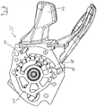
- FIG. 1 an inventive stepper 20 is shown in an oblique top view.
- the stepper 20 includes a base plate 22 to which a pulley assembly 24 is rotatably mounted about an axis X. This has been omitted for reasons of clarity on the presentation of the attachment device.
- the toothed disc assembly comprises an upper toothed disc 24a and a lower toothed disc 24b, which on the one hand rotatably with each other, and on the other hand rotatably connected to a not shown Seilabilityvorraum.
- the stepping switch comprises a locking pawl 28 which is pivotable about a second axis Y and which has at its one end a locking projection 30 facing the toothed disk arrangement 24, and at another end a securing projection 32 likewise facing the toothed disk arrangement 24.
- the axis of rotation X of the toothed disk assembly and the pivot axis Y of the locking pawl 28 are aligned parallel to each other.
- the locking pawl 28 on the side at which the securing projection is at 32 an obliquely upward engagement element 34, which can be engaged by a first actuating lever not shown here, that the locking pawl 28 is pivoted about its pivot axis Y.
- the stepper switch according to the invention can be used, for example, to operate a bicycle gearshift, and here in particular a chain derailleur.
- the lower toothed disc 24b has on its outer periphery at 1-10 designated angular positions in the following also designated by the reference numerals 1-10 teeth, of which, however, only the teeth corresponding to the angular position 7-10 FIG. 1 are shown. Furthermore, in the following also the operating positions of the toothed disc assembly 28, wherein each of the Arretiervorsprung 30 and one of the teeth 1-10 are engaged, referred to as the first to tenth operating position.
- the first operating position of the operating position corresponds to the maximum intake of an operation cable received by the cable receiving device, while in the further operating positions the operating cable is successively pulled out further.
- the upper toothed disc 24a also has a plurality of teeth 26, the number of which corresponds to the number of teeth of the lower toothed disc, of which, however, only four are shown analogous to the representation of the upper toothed disc.
- step switch 20 shown comprises a retraction mechanism 36, which can be actuated by means of a second actuating lever 38.
- a retraction mechanism 36 which can be actuated by means of a second actuating lever 38.
- An explanation of the operation of the feed mechanism 36 will be omitted here, for a detailed explanation of such a mechanism is rather on the EP 1 366 981 A2 directed.
- the teeth 1-10 and the locking projection 30 are in this case beveled such that a rotation of the toothed disc assembly 24 by means of the retraction mechanism counterclockwise is possible when the locking pawl 28 is in its holding position.
- the locking pawl 28 is briefly pivoted out of the holding position by the interaction of the bevelled teeth 1-10 and the locking projection 30, so that the respective tooth 1-10 can slide under the locking projection 30. This process corresponds to shifting from a higher gear to a lower gear.
- the user wishes to shift upwards from a low gear, he must exercise a force on the engagement projection 34 of the locking pawl 28 by means of the actuating lever, which is not the first one shown.
- the locking pawl 28 is pivoted out of its holding position into a securing position in which its securing projection 32 is pivoted against the toothed disc 24a, but its locking projection 30 is pivoted away from engagement with the toothing of the toothed disc 24b. Since, as mentioned, the toothed disc assembly 24 is biased clockwise about the axis of rotation X, it begins to rotate in that direction.
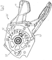
- FIG. 2-6 is based on a second embodiment of a step switch 20 'according to the invention again such a release operation illustrated step by step.
- the toothed disc assembly 24 'shown there consists only of a single toothed disc 24', which has a number of teeth 1-9 and AE, which is greater than the number of intended operating positions of the toothed disc assembly.
- the in the Figures 2-8 shown second embodiment of a holding and releasing mechanism 29 'according to the invention is formed by the interaction of the toothed disc assembly 24' and the locking pawl 28 '.
- the toothed disc assembly 24 ' a total of 14 teeth 1-9 and AE, which are all in a single, perpendicular to the pointing in the plane of rotation in the axis X of the toothed disc assembly 24' lying plane.
- the locking pawl 28 ' is formed such that its' locking projection 30 'and its locking projection 32' are in that same level.
- a release operation is illustrated which corresponds to a transition from a fourth to a fifth actuation position.
- the tooth 4 of the toothed disc assembly 24 'and the locking projection 30' located in its holding position locking pawl 28 'in engagement. Since the toothed disc assembly 24 'in the clockwise direction and the locking pawl 28' are biased in the holding position shown, the toothed disc assembly 24 'is set in this operating position.
- FIG. 3 is now a beginning release operation of the locking pawl 28 'shown which is triggered by a push-up of the operating lever 40 by a user.
- This operating lever 40 acts on the engaging projection 34 of the locking pawl 28 'and pivots it out of its holding position in the direction of its securing position.
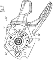
- FIG. 7 is a state of the stepper shown in which the toothed disc assembly 24 'is held in its ninth operating position. It can be seen that by selecting the number of teeth 1-9 and AE of the toothed disc assembly 24 'now counterclockwise from tooth A looked no tooth on the toothed disc assembly 24' is available, which in a further release operation with the securing projection 32 'of the locking pawl 28' could engage. In this way, it is achieved that the upshifting from the ninth to the tenth operating position is achieved without an intermittent stop of the toothed disc assembly 24 '.
- the tenth operating position ie the actuating position maximum extension
- the operating position maximum extract is defined only blurred and is defined by the operated by means of the switch device, namely an actuating position of this device, which corresponds to the state of maximum pull-out and for example by a adjustable stop this device, such as a derailleur device of a bicycle derailleur is defined.
- This operating position maximum extension is in FIG. 8 shown.
- the rotatably with the pulley assembly 24 ', above it arranged cam member 42 can be seen, which was not shown for reasons of clarity in the previous figures.
- maximum extension extracting engagement occurs between the cam member 42 and a Festsetzvorsprung 44 which extends at the end of the locking pawl 28 'upwards, on which also the locking projection 30' is provided.
- cam member 42 and cable receiving device 46 is also on the FIG. 9 directed.
- the assembly formed by the toothed pulley 24 'and the cable receiving device 46 is shown in the region of the teeth 7-9, E and D from the side.
- the cam member is seen from the base plate 22 from above the toothed disc 24 'rotatably attached to the cable receiving device 46 and spans substantially the teeth 8, 9 and E of the toothed disc 24'. Since the cam element 42 does not protrude into the plane of the toothed disc 24 ', regardless of the rotational position of the toothed disc 24 'with respect to in FIG.
- the system formed from stepper 20, operating cable 48 and actuatable by the stepper device 50 system is roughly schematically illustrated.
- the actuatable device 50 may be, in particular, a bicycle derailleur, a derailleur which can be actuated by means of the actuation cable 48 being motion-coupled to an actuation element 52 on which the actuation cable 48 (for example the cable of a Bowden cable) is suspended.
- the derailleur 50 further includes a further spring element 54 which biases the pivotable about the pivot axis S actuator 52 and thus also the operating cable 48 in an operating position maximum excerpt of the operating cable 48. For fine adjustment of this operating position maximum extension and thus an operating position of the derailleur is in the actuatable device 50 along an axis Z adjustable end stop 56 is provided.
- a holding and releasing mechanism for holding and releasing a cable receiving device such as a stepper, comprising one of the cable receiving device integrally associated or rotatably connected thereto or connectable to this about a first axis (X) rotatable toothed pulley assembly, which on its outer circumference a plurality of teeth having; an adjustable, preferably about a second axis (Y) pivotable locking pawl, which in a first position, in particular a first pivot position, located in different first rotational positions Zahnommenan extract with a locking projection with one of the respective first rotational position associated, serving as a locking tooth of the plurality of Engages teeth to hold the pulley assembly and thus the cable receiving device in the respective first rotational position or stop, and which in a second position, in particular a second Pivoting position, when located in different second rotational positions of the toothed disc assembly with a securing projection associated with a respective second rotational position, serving as a safety tooth tooth of the plurality of teeth to hold
Applications Claiming Priority (2)
| Application Number | Priority Date | Filing Date | Title |
|---|---|---|---|
| DE102013216932.9A DE102013216932A1 (de) | 2013-08-26 | 2013-08-26 | Halte- und Freigabemechanik zum Halten und Freigeben einer Seilaufnahmevorrichtung |
| EP14002901.8A EP2842860B2 (fr) | 2013-08-26 | 2014-08-21 | Mécanique de retenue et de desserrage d'un dispositif de logement de câble |
Related Parent Applications (2)
| Application Number | Title | Priority Date | Filing Date |
|---|---|---|---|
| EP14002901.8A Division EP2842860B2 (fr) | 2013-08-26 | 2014-08-21 | Mécanique de retenue et de desserrage d'un dispositif de logement de câble |
| EP14002901.8A Division-Into EP2842860B2 (fr) | 2013-08-26 | 2014-08-21 | Mécanique de retenue et de desserrage d'un dispositif de logement de câble |
Publications (3)
| Publication Number | Publication Date |
|---|---|
| EP3564114A2 true EP3564114A2 (fr) | 2019-11-06 |
| EP3564114A3 EP3564114A3 (fr) | 2020-01-08 |
| EP3564114B1 EP3564114B1 (fr) | 2021-06-09 |
Family
ID=51485408
Family Applications (2)
| Application Number | Title | Priority Date | Filing Date |
|---|---|---|---|
| EP19000235.2A Active EP3564114B1 (fr) | 2013-08-26 | 2014-08-21 | Mécanique de retenue et de desserrage d'un dispositif de logement de câble |
| EP14002901.8A Active EP2842860B2 (fr) | 2013-08-26 | 2014-08-21 | Mécanique de retenue et de desserrage d'un dispositif de logement de câble |
Family Applications After (1)
| Application Number | Title | Priority Date | Filing Date |
|---|---|---|---|
| EP14002901.8A Active EP2842860B2 (fr) | 2013-08-26 | 2014-08-21 | Mécanique de retenue et de desserrage d'un dispositif de logement de câble |
Country Status (3)
| Country | Link |
|---|---|
| US (2) | US9791002B2 (fr) |
| EP (2) | EP3564114B1 (fr) |
| DE (1) | DE102013216932A1 (fr) |
Families Citing this family (4)
| Publication number | Priority date | Publication date | Assignee | Title |
|---|---|---|---|---|
| US10131406B2 (en) * | 2015-09-10 | 2018-11-20 | Shimano Inc. | Bicycle operating device |
| CN105438397B (zh) * | 2015-12-29 | 2018-08-24 | 速瑞达自行车零件(佛山)有限公司 | 一种自行车变速装置 |
| USD842258S1 (en) * | 2016-03-29 | 2019-03-05 | Kevin Somers | Electrical circuit breaker charge cam |
| CN108583767A (zh) * | 2018-06-15 | 2018-09-28 | 速瑞达自行车零件(佛山)有限公司 | 一种助力自行车的调速方法及调速器 |
Citations (4)
| Publication number | Priority date | Publication date | Assignee | Title |
|---|---|---|---|---|
| EP0361335A2 (fr) | 1988-09-24 | 1990-04-04 | Shimano Inc. | Levier de changement de vitesses pour vélo |
| FR2701917A1 (fr) | 1993-02-26 | 1994-09-02 | Sachs Ind Sa | Dispositif à deux organes de commande pour dérailleur de cycle. |
| EP1366981A2 (fr) | 2002-05-31 | 2003-12-03 | SRAM Deutschland GmbH | Dispositif de déblocage pour changement de vitesse |
| EP1232940B2 (fr) | 1996-01-19 | 2012-08-22 | Shimano Inc. | Dispositif de changement de vitesse pour bicyclette |
Family Cites Families (20)
| Publication number | Priority date | Publication date | Assignee | Title |
|---|---|---|---|---|
| GB2169065B (en) | 1984-12-28 | 1987-12-23 | Sturmey Archer Ltd | Indexing mechanisms and controls embodying the same |
| US5241878A (en) | 1988-11-29 | 1993-09-07 | Shimano, Inc. | Bicycle control device |
| JP2602671Y2 (ja) | 1992-01-21 | 2000-01-24 | 株式会社シマノ | 自転車用の表示装置付き変速操作装置 |
| JP3205709B2 (ja) | 1996-12-19 | 2001-09-04 | 株式会社シマノ | 自転車用副変速操作装置、主変速操作装置及び変速操作システム |
| DE19915336A1 (de) | 1999-04-03 | 2000-10-05 | Sram De Gmbh | Schalter für ein Fahrradgetriebe |
| US6450060B1 (en) * | 2000-03-17 | 2002-09-17 | Shimano, Inc. | Bicycle shift device having a linearly sliding shift lever operated by a pivoting cover |
| US6694840B2 (en) † | 2002-01-10 | 2004-02-24 | Shimano Inc. | Bicycle shift operating device for bicycle transmission |
| DE10205278B4 (de) * | 2002-02-08 | 2019-03-14 | Sram Deutschland Gmbh | Freigabemechanismus |
| US7152497B2 (en) | 2003-01-27 | 2006-12-26 | Shimano, Inc. | Method and apparatus for shifting a bicycle transmission by multiple steps |
| US7650813B2 (en) * | 2005-05-19 | 2010-01-26 | Shimano Inc. | Position control mechanism for bicycle control device |
| TWM312495U (en) * | 2006-04-25 | 2007-05-21 | Ad Ii Engineering Inc | Gearshift operation apparatus for bicycle |
| CN2897804Y (zh) * | 2006-04-28 | 2007-05-09 | 台湾微转股份有限公司 | 自行车的变速操作装置 |
| US7628095B2 (en) | 2006-05-10 | 2009-12-08 | Shimano Inc. | Bicycle shifting mechanism |
| DE102008048134C5 (de) * | 2008-09-20 | 2018-09-27 | Sram Deutschland Gmbh | Schalter zur Betätigung eines Getriebes an einem Fahrrad |
| US8584550B1 (en) * | 2009-05-18 | 2013-11-19 | John L. Calendrille, Jr. | Shift lever arrangement for a bicycle |
| US8272293B2 (en) | 2010-08-24 | 2012-09-25 | Shimano Inc. | Bicycle shift operating device |
| US9327793B2 (en) * | 2011-10-01 | 2016-05-03 | Shimano Inc. | Bicycle operating device |
| US8746105B2 (en) * | 2012-02-24 | 2014-06-10 | Shimano Inc. | Bicycle operating device |
| US9132887B2 (en) * | 2012-02-24 | 2015-09-15 | Shimano Inc. | Bicycle operating device |
| US8720301B2 (en) * | 2012-02-24 | 2014-05-13 | Shimano Inc. | Bicycle operating device |
-
2013
- 2013-08-26 DE DE102013216932.9A patent/DE102013216932A1/de not_active Ceased
-
2014
- 2014-08-21 EP EP19000235.2A patent/EP3564114B1/fr active Active
- 2014-08-21 EP EP14002901.8A patent/EP2842860B2/fr active Active
- 2014-08-26 US US14/468,419 patent/US9791002B2/en active Active
-
2017
- 2017-09-29 US US15/720,819 patent/US11035422B2/en active Active
Patent Citations (4)
| Publication number | Priority date | Publication date | Assignee | Title |
|---|---|---|---|---|
| EP0361335A2 (fr) | 1988-09-24 | 1990-04-04 | Shimano Inc. | Levier de changement de vitesses pour vélo |
| FR2701917A1 (fr) | 1993-02-26 | 1994-09-02 | Sachs Ind Sa | Dispositif à deux organes de commande pour dérailleur de cycle. |
| EP1232940B2 (fr) | 1996-01-19 | 2012-08-22 | Shimano Inc. | Dispositif de changement de vitesse pour bicyclette |
| EP1366981A2 (fr) | 2002-05-31 | 2003-12-03 | SRAM Deutschland GmbH | Dispositif de déblocage pour changement de vitesse |
Also Published As
| Publication number | Publication date |
|---|---|
| EP2842860A2 (fr) | 2015-03-04 |
| EP3564114B1 (fr) | 2021-06-09 |
| EP2842860B2 (fr) | 2022-07-27 |
| EP3564114A3 (fr) | 2020-01-08 |
| US11035422B2 (en) | 2021-06-15 |
| US20180023637A1 (en) | 2018-01-25 |
| EP2842860A3 (fr) | 2015-07-15 |
| US20150075321A1 (en) | 2015-03-19 |
| DE102013216932A1 (de) | 2015-02-26 |
| US9791002B2 (en) | 2017-10-17 |
| EP2842860B1 (fr) | 2019-05-15 |
Similar Documents
| Publication | Publication Date | Title |
|---|---|---|
| EP2504219B2 (fr) | Colonne de direction pour un véhicule à moteur | |
| EP3218246B1 (fr) | Colonne de direction comportant une butée longitudinale présentant une fonction de libération en cas d'accident | |
| DE102005013901B4 (de) | Baumständer, insbesondere Christbaumständer mit verbesserter Lösefunktion | |
| EP3482024A1 (fr) | Dispositif de préhension comprenant une poignée à fleur | |
| DE102008048134C5 (de) | Schalter zur Betätigung eines Getriebes an einem Fahrrad | |
| DE19711006A1 (de) | Kopfstütze für Kraftfahrzeugsitz | |
| DE102012110648B4 (de) | Verriegelungselement, Verbindungsanordnung, Anordnung aus einem ersten Bauteil und einem zweiten Bauteil und Verfahren zur Montage einer solchen Anordnung | |
| DE102014116169A1 (de) | Spannklaue zur Anbringung an einer Gleitschiene eines Operationstisches | |
| EP2842860B1 (fr) | Mécanique de retenue et de desserrage d'un dispositif de logement de câble | |
| EP1989960A1 (fr) | Ferrure à cran d'arrêt | |
| DE102015101829A1 (de) | Spannklaue zur Anbringung an einer Gleitschiene eines Operationstisches | |
| DE69909975T2 (de) | Vorrichtung zum Betätigen des Visiers von Helmen für Motorradfahrer und dergleichen | |
| WO2012084595A1 (fr) | Dispositif d'ouverture et de fermeture pour parties de meuble mobiles | |
| EP2497883A2 (fr) | Dispositif d'arrêt d'extraction | |
| DE4009503C2 (fr) | ||
| DE102013016860B4 (de) | Verstellvorrichtung mit einem festen Element und einem verstellbaren Element | |
| DE2845485A1 (de) | Einstellvorrichtung mit einem um eine achse schwenkbaren einstellorgan | |
| WO2014135145A1 (fr) | Système de verrouillage de glissière de siège de véhicule et glissière de siège | |
| DE102014108902A1 (de) | Spannschloss für eine Gleitschutzkette | |
| DE3013953A1 (de) | Schnallenverschluss fuer schuhe, insbesondere fuer ski- oder bergstiefel | |
| EP0318720B1 (fr) | Dispositif automatique de réglage de la longueur d'un câble Bowden | |
| EP3013634B1 (fr) | Dispositif de réglage comprenant un élément fixe, un élément réglable et un premier système de blocage | |
| DE3103525A1 (de) | Vorrichtung zum bearbeiten der anschlussdraehte von elektrischen bauelementen | |
| DE3322903C1 (de) | Hebeltrieb mit mechanischer und/oder automatischer Einstellbarkeit der Hebelkontakte | |
| DE2052017C3 (de) | Tabelliereinrichtung für Schreib- oder ähnliche Büromaschinen |
Legal Events
| Date | Code | Title | Description |
|---|---|---|---|
| PUAI | Public reference made under article 153(3) epc to a published international application that has entered the european phase |
Free format text: ORIGINAL CODE: 0009012 |
|
| STAA | Information on the status of an ep patent application or granted ep patent |
Free format text: STATUS: THE APPLICATION HAS BEEN PUBLISHED |
|
| AC | Divisional application: reference to earlier application |
Ref document number: 2842860 Country of ref document: EP Kind code of ref document: P |
|
| AK | Designated contracting states |
Kind code of ref document: A2 Designated state(s): AL AT BE BG CH CY CZ DE DK EE ES FI FR GB GR HR HU IE IS IT LI LT LU LV MC MK MT NL NO PL PT RO RS SE SI SK SM TR |
|
| PUAL | Search report despatched |
Free format text: ORIGINAL CODE: 0009013 |
|
| AK | Designated contracting states |
Kind code of ref document: A3 Designated state(s): AL AT BE BG CH CY CZ DE DK EE ES FI FR GB GR HR HU IE IS IT LI LT LU LV MC MK MT NL NO PL PT RO RS SE SI SK SM TR |
|
| RIC1 | Information provided on ipc code assigned before grant |
Ipc: B62K 23/06 20060101ALI20191204BHEP Ipc: B62M 25/04 20060101AFI20191204BHEP |
|
| STAA | Information on the status of an ep patent application or granted ep patent |
Free format text: STATUS: REQUEST FOR EXAMINATION WAS MADE |
|
| 17P | Request for examination filed |
Effective date: 20200706 |
|
| GRAP | Despatch of communication of intention to grant a patent |
Free format text: ORIGINAL CODE: EPIDOSNIGR1 |
|
| STAA | Information on the status of an ep patent application or granted ep patent |
Free format text: STATUS: GRANT OF PATENT IS INTENDED |
|
| INTG | Intention to grant announced |
Effective date: 20200828 |
|
| GRAJ | Information related to disapproval of communication of intention to grant by the applicant or resumption of examination proceedings by the epo deleted |
Free format text: ORIGINAL CODE: EPIDOSDIGR1 |
|
| STAA | Information on the status of an ep patent application or granted ep patent |
Free format text: STATUS: REQUEST FOR EXAMINATION WAS MADE |
|
| INTC | Intention to grant announced (deleted) | ||
| GRAP | Despatch of communication of intention to grant a patent |
Free format text: ORIGINAL CODE: EPIDOSNIGR1 |
|
| STAA | Information on the status of an ep patent application or granted ep patent |
Free format text: STATUS: GRANT OF PATENT IS INTENDED |
|
| INTG | Intention to grant announced |
Effective date: 20210126 |
|
| GRAS | Grant fee paid |
Free format text: ORIGINAL CODE: EPIDOSNIGR3 |
|
| GRAA | (expected) grant |
Free format text: ORIGINAL CODE: 0009210 |
|
| STAA | Information on the status of an ep patent application or granted ep patent |
Free format text: STATUS: THE PATENT HAS BEEN GRANTED |
|
| AC | Divisional application: reference to earlier application |
Ref document number: 2842860 Country of ref document: EP Kind code of ref document: P |
|
| AK | Designated contracting states |
Kind code of ref document: B1 Designated state(s): AL AT BE BG CH CY CZ DE DK EE ES FI FR GB GR HR HU IE IS IT LI LT LU LV MC MK MT NL NO PL PT RO RS SE SI SK SM TR |
|
| REG | Reference to a national code |
Ref country code: GB Ref legal event code: FG4D Free format text: NOT ENGLISH |
|
| REG | Reference to a national code |
Ref country code: AT Ref legal event code: REF Ref document number: 1400275 Country of ref document: AT Kind code of ref document: T Effective date: 20210615 Ref country code: CH Ref legal event code: EP |
|
| REG | Reference to a national code |
Ref country code: DE Ref legal event code: R096 Ref document number: 502014015666 Country of ref document: DE |
|
| REG | Reference to a national code |
Ref country code: IE Ref legal event code: FG4D Free format text: LANGUAGE OF EP DOCUMENT: GERMAN |
|
| REG | Reference to a national code |
Ref country code: NL Ref legal event code: FP |
|
| REG | Reference to a national code |
Ref country code: LT Ref legal event code: MG9D |
|
| PG25 | Lapsed in a contracting state [announced via postgrant information from national office to epo] |
Ref country code: BG Free format text: LAPSE BECAUSE OF FAILURE TO SUBMIT A TRANSLATION OF THE DESCRIPTION OR TO PAY THE FEE WITHIN THE PRESCRIBED TIME-LIMIT Effective date: 20210909 Ref country code: HR Free format text: LAPSE BECAUSE OF FAILURE TO SUBMIT A TRANSLATION OF THE DESCRIPTION OR TO PAY THE FEE WITHIN THE PRESCRIBED TIME-LIMIT Effective date: 20210609 Ref country code: LT Free format text: LAPSE BECAUSE OF FAILURE TO SUBMIT A TRANSLATION OF THE DESCRIPTION OR TO PAY THE FEE WITHIN THE PRESCRIBED TIME-LIMIT Effective date: 20210609 Ref country code: FI Free format text: LAPSE BECAUSE OF FAILURE TO SUBMIT A TRANSLATION OF THE DESCRIPTION OR TO PAY THE FEE WITHIN THE PRESCRIBED TIME-LIMIT Effective date: 20210609 |
|
| PG25 | Lapsed in a contracting state [announced via postgrant information from national office to epo] |
Ref country code: SE Free format text: LAPSE BECAUSE OF FAILURE TO SUBMIT A TRANSLATION OF THE DESCRIPTION OR TO PAY THE FEE WITHIN THE PRESCRIBED TIME-LIMIT Effective date: 20210609 Ref country code: RS Free format text: LAPSE BECAUSE OF FAILURE TO SUBMIT A TRANSLATION OF THE DESCRIPTION OR TO PAY THE FEE WITHIN THE PRESCRIBED TIME-LIMIT Effective date: 20210609 Ref country code: LV Free format text: LAPSE BECAUSE OF FAILURE TO SUBMIT A TRANSLATION OF THE DESCRIPTION OR TO PAY THE FEE WITHIN THE PRESCRIBED TIME-LIMIT Effective date: 20210609 Ref country code: NO Free format text: LAPSE BECAUSE OF FAILURE TO SUBMIT A TRANSLATION OF THE DESCRIPTION OR TO PAY THE FEE WITHIN THE PRESCRIBED TIME-LIMIT Effective date: 20210909 Ref country code: GR Free format text: LAPSE BECAUSE OF FAILURE TO SUBMIT A TRANSLATION OF THE DESCRIPTION OR TO PAY THE FEE WITHIN THE PRESCRIBED TIME-LIMIT Effective date: 20210910 |
|
| PG25 | Lapsed in a contracting state [announced via postgrant information from national office to epo] |
Ref country code: EE Free format text: LAPSE BECAUSE OF FAILURE TO SUBMIT A TRANSLATION OF THE DESCRIPTION OR TO PAY THE FEE WITHIN THE PRESCRIBED TIME-LIMIT Effective date: 20210609 Ref country code: ES Free format text: LAPSE BECAUSE OF FAILURE TO SUBMIT A TRANSLATION OF THE DESCRIPTION OR TO PAY THE FEE WITHIN THE PRESCRIBED TIME-LIMIT Effective date: 20210609 Ref country code: SK Free format text: LAPSE BECAUSE OF FAILURE TO SUBMIT A TRANSLATION OF THE DESCRIPTION OR TO PAY THE FEE WITHIN THE PRESCRIBED TIME-LIMIT Effective date: 20210609 Ref country code: CZ Free format text: LAPSE BECAUSE OF FAILURE TO SUBMIT A TRANSLATION OF THE DESCRIPTION OR TO PAY THE FEE WITHIN THE PRESCRIBED TIME-LIMIT Effective date: 20210609 Ref country code: SM Free format text: LAPSE BECAUSE OF FAILURE TO SUBMIT A TRANSLATION OF THE DESCRIPTION OR TO PAY THE FEE WITHIN THE PRESCRIBED TIME-LIMIT Effective date: 20210609 Ref country code: RO Free format text: LAPSE BECAUSE OF FAILURE TO SUBMIT A TRANSLATION OF THE DESCRIPTION OR TO PAY THE FEE WITHIN THE PRESCRIBED TIME-LIMIT Effective date: 20210609 Ref country code: PT Free format text: LAPSE BECAUSE OF FAILURE TO SUBMIT A TRANSLATION OF THE DESCRIPTION OR TO PAY THE FEE WITHIN THE PRESCRIBED TIME-LIMIT Effective date: 20211011 |
|
| PG25 | Lapsed in a contracting state [announced via postgrant information from national office to epo] |
Ref country code: PL Free format text: LAPSE BECAUSE OF FAILURE TO SUBMIT A TRANSLATION OF THE DESCRIPTION OR TO PAY THE FEE WITHIN THE PRESCRIBED TIME-LIMIT Effective date: 20210609 |
|
| REG | Reference to a national code |
Ref country code: DE Ref legal event code: R097 Ref document number: 502014015666 Country of ref document: DE |
|
| REG | Reference to a national code |
Ref country code: CH Ref legal event code: PL |
|
| PG25 | Lapsed in a contracting state [announced via postgrant information from national office to epo] |
Ref country code: MC Free format text: LAPSE BECAUSE OF FAILURE TO SUBMIT A TRANSLATION OF THE DESCRIPTION OR TO PAY THE FEE WITHIN THE PRESCRIBED TIME-LIMIT Effective date: 20210609 |
|
| PLBE | No opposition filed within time limit |
Free format text: ORIGINAL CODE: 0009261 |
|
| STAA | Information on the status of an ep patent application or granted ep patent |
Free format text: STATUS: NO OPPOSITION FILED WITHIN TIME LIMIT |
|
| REG | Reference to a national code |
Ref country code: BE Ref legal event code: MM Effective date: 20210831 |
|
| PG25 | Lapsed in a contracting state [announced via postgrant information from national office to epo] |
Ref country code: LI Free format text: LAPSE BECAUSE OF NON-PAYMENT OF DUE FEES Effective date: 20210831 Ref country code: DK Free format text: LAPSE BECAUSE OF FAILURE TO SUBMIT A TRANSLATION OF THE DESCRIPTION OR TO PAY THE FEE WITHIN THE PRESCRIBED TIME-LIMIT Effective date: 20210609 Ref country code: CH Free format text: LAPSE BECAUSE OF NON-PAYMENT OF DUE FEES Effective date: 20210831 |
|
| 26N | No opposition filed |
Effective date: 20220310 |
|
| GBPC | Gb: european patent ceased through non-payment of renewal fee |
Effective date: 20210909 |
|
| PG25 | Lapsed in a contracting state [announced via postgrant information from national office to epo] |
Ref country code: LU Free format text: LAPSE BECAUSE OF NON-PAYMENT OF DUE FEES Effective date: 20210821 Ref country code: AL Free format text: LAPSE BECAUSE OF FAILURE TO SUBMIT A TRANSLATION OF THE DESCRIPTION OR TO PAY THE FEE WITHIN THE PRESCRIBED TIME-LIMIT Effective date: 20210609 |
|
| PG25 | Lapsed in a contracting state [announced via postgrant information from national office to epo] |
Ref country code: IT Free format text: LAPSE BECAUSE OF FAILURE TO SUBMIT A TRANSLATION OF THE DESCRIPTION OR TO PAY THE FEE WITHIN THE PRESCRIBED TIME-LIMIT Effective date: 20210609 Ref country code: IE Free format text: LAPSE BECAUSE OF NON-PAYMENT OF DUE FEES Effective date: 20210821 Ref country code: GB Free format text: LAPSE BECAUSE OF NON-PAYMENT OF DUE FEES Effective date: 20210909 Ref country code: BE Free format text: LAPSE BECAUSE OF NON-PAYMENT OF DUE FEES Effective date: 20210831 |
|
| REG | Reference to a national code |
Ref country code: AT Ref legal event code: MM01 Ref document number: 1400275 Country of ref document: AT Kind code of ref document: T Effective date: 20210821 |
|
| PG25 | Lapsed in a contracting state [announced via postgrant information from national office to epo] |
Ref country code: AT Free format text: LAPSE BECAUSE OF NON-PAYMENT OF DUE FEES Effective date: 20210821 |
|
| P01 | Opt-out of the competence of the unified patent court (upc) registered |
Effective date: 20230523 |
|
| PG25 | Lapsed in a contracting state [announced via postgrant information from national office to epo] |
Ref country code: CY Free format text: LAPSE BECAUSE OF FAILURE TO SUBMIT A TRANSLATION OF THE DESCRIPTION OR TO PAY THE FEE WITHIN THE PRESCRIBED TIME-LIMIT Effective date: 20210609 |
|
| PG25 | Lapsed in a contracting state [announced via postgrant information from national office to epo] |
Ref country code: HU Free format text: LAPSE BECAUSE OF FAILURE TO SUBMIT A TRANSLATION OF THE DESCRIPTION OR TO PAY THE FEE WITHIN THE PRESCRIBED TIME-LIMIT; INVALID AB INITIO Effective date: 20140821 |
|
| PGFP | Annual fee paid to national office [announced via postgrant information from national office to epo] |
Ref country code: NL Payment date: 20230821 Year of fee payment: 10 |
|
| PGFP | Annual fee paid to national office [announced via postgrant information from national office to epo] |
Ref country code: FR Payment date: 20230828 Year of fee payment: 10 Ref country code: DE Payment date: 20230830 Year of fee payment: 10 |
|
| PG25 | Lapsed in a contracting state [announced via postgrant information from national office to epo] |
Ref country code: MK Free format text: LAPSE BECAUSE OF FAILURE TO SUBMIT A TRANSLATION OF THE DESCRIPTION OR TO PAY THE FEE WITHIN THE PRESCRIBED TIME-LIMIT Effective date: 20210609 |