EP3561336B1 - Bremsmodul für ein antriebssystem, antriebssystem und herstellungsverfahren für ein bremsmodul - Google Patents
Bremsmodul für ein antriebssystem, antriebssystem und herstellungsverfahren für ein bremsmodul Download PDFInfo
- Publication number
- EP3561336B1 EP3561336B1 EP19169291.2A EP19169291A EP3561336B1 EP 3561336 B1 EP3561336 B1 EP 3561336B1 EP 19169291 A EP19169291 A EP 19169291A EP 3561336 B1 EP3561336 B1 EP 3561336B1
- Authority
- EP
- European Patent Office
- Prior art keywords
- brake disc
- thrust washer
- brake
- carrier
- brake module
- Prior art date
- Legal status (The legal status is an assumption and is not a legal conclusion. Google has not performed a legal analysis and makes no representation as to the accuracy of the status listed.)
- Active
Links
Images




Classifications
-
- F—MECHANICAL ENGINEERING; LIGHTING; HEATING; WEAPONS; BLASTING
- F16—ENGINEERING ELEMENTS AND UNITS; GENERAL MEASURES FOR PRODUCING AND MAINTAINING EFFECTIVE FUNCTIONING OF MACHINES OR INSTALLATIONS; THERMAL INSULATION IN GENERAL
- F16D—COUPLINGS FOR TRANSMITTING ROTATION; CLUTCHES; BRAKES
- F16D71/00—Mechanisms for bringing members to rest in a predetermined position
-
- E—FIXED CONSTRUCTIONS
- E05—LOCKS; KEYS; WINDOW OR DOOR FITTINGS; SAFES
- E05F—DEVICES FOR MOVING WINGS INTO OPEN OR CLOSED POSITION; CHECKS FOR WINGS; WING FITTINGS NOT OTHERWISE PROVIDED FOR, CONCERNED WITH THE FUNCTIONING OF THE WING
- E05F15/00—Power-operated mechanisms for wings
- E05F15/60—Power-operated mechanisms for wings using electrical actuators
- E05F15/603—Power-operated mechanisms for wings using electrical actuators using rotary electromotors
-
- E—FIXED CONSTRUCTIONS
- E05—LOCKS; KEYS; WINDOW OR DOOR FITTINGS; SAFES
- E05F—DEVICES FOR MOVING WINGS INTO OPEN OR CLOSED POSITION; CHECKS FOR WINGS; WING FITTINGS NOT OTHERWISE PROVIDED FOR, CONCERNED WITH THE FUNCTIONING OF THE WING
- E05F5/00—Braking devices, e.g. checks; Stops; Buffers
-
- F—MECHANICAL ENGINEERING; LIGHTING; HEATING; WEAPONS; BLASTING
- F16—ENGINEERING ELEMENTS AND UNITS; GENERAL MEASURES FOR PRODUCING AND MAINTAINING EFFECTIVE FUNCTIONING OF MACHINES OR INSTALLATIONS; THERMAL INSULATION IN GENERAL
- F16D—COUPLINGS FOR TRANSMITTING ROTATION; CLUTCHES; BRAKES
- F16D55/00—Brakes with substantially-radial braking surfaces pressed together in axial direction, e.g. disc brakes
- F16D55/02—Brakes with substantially-radial braking surfaces pressed together in axial direction, e.g. disc brakes with axially-movable discs or pads pressed against axially-located rotating members
- F16D55/22—Brakes with substantially-radial braking surfaces pressed together in axial direction, e.g. disc brakes with axially-movable discs or pads pressed against axially-located rotating members by clamping an axially-located rotating disc between movable braking members, e.g. movable brake discs or brake pads
-
- F—MECHANICAL ENGINEERING; LIGHTING; HEATING; WEAPONS; BLASTING
- F16—ENGINEERING ELEMENTS AND UNITS; GENERAL MEASURES FOR PRODUCING AND MAINTAINING EFFECTIVE FUNCTIONING OF MACHINES OR INSTALLATIONS; THERMAL INSULATION IN GENERAL
- F16D—COUPLINGS FOR TRANSMITTING ROTATION; CLUTCHES; BRAKES
- F16D59/00—Self-acting brakes, e.g. coming into operation at a predetermined speed
-
- F—MECHANICAL ENGINEERING; LIGHTING; HEATING; WEAPONS; BLASTING
- F16—ENGINEERING ELEMENTS AND UNITS; GENERAL MEASURES FOR PRODUCING AND MAINTAINING EFFECTIVE FUNCTIONING OF MACHINES OR INSTALLATIONS; THERMAL INSULATION IN GENERAL
- F16D—COUPLINGS FOR TRANSMITTING ROTATION; CLUTCHES; BRAKES
- F16D65/00—Parts or details
- F16D65/005—Components of axially engaging brakes not otherwise provided for
- F16D65/0081—Brake covers
-
- F—MECHANICAL ENGINEERING; LIGHTING; HEATING; WEAPONS; BLASTING
- F16—ENGINEERING ELEMENTS AND UNITS; GENERAL MEASURES FOR PRODUCING AND MAINTAINING EFFECTIVE FUNCTIONING OF MACHINES OR INSTALLATIONS; THERMAL INSULATION IN GENERAL
- F16D—COUPLINGS FOR TRANSMITTING ROTATION; CLUTCHES; BRAKES
- F16D65/00—Parts or details
- F16D65/02—Braking members; Mounting thereof
- F16D65/12—Discs; Drums for disc brakes
- F16D65/123—Discs; Drums for disc brakes comprising an annular disc secured to a hub member; Discs characterised by means for mounting
-
- F—MECHANICAL ENGINEERING; LIGHTING; HEATING; WEAPONS; BLASTING
- F16—ENGINEERING ELEMENTS AND UNITS; GENERAL MEASURES FOR PRODUCING AND MAINTAINING EFFECTIVE FUNCTIONING OF MACHINES OR INSTALLATIONS; THERMAL INSULATION IN GENERAL
- F16D—COUPLINGS FOR TRANSMITTING ROTATION; CLUTCHES; BRAKES
- F16D65/00—Parts or details
- F16D65/02—Braking members; Mounting thereof
- F16D65/12—Discs; Drums for disc brakes
- F16D65/125—Discs; Drums for disc brakes characterised by the material used for the disc body
-
- F—MECHANICAL ENGINEERING; LIGHTING; HEATING; WEAPONS; BLASTING
- F16—ENGINEERING ELEMENTS AND UNITS; GENERAL MEASURES FOR PRODUCING AND MAINTAINING EFFECTIVE FUNCTIONING OF MACHINES OR INSTALLATIONS; THERMAL INSULATION IN GENERAL
- F16D—COUPLINGS FOR TRANSMITTING ROTATION; CLUTCHES; BRAKES
- F16D65/00—Parts or details
- F16D65/02—Braking members; Mounting thereof
- F16D65/12—Discs; Drums for disc brakes
- F16D65/127—Discs; Drums for disc brakes characterised by properties of the disc surface; Discs lined with friction material
-
- F—MECHANICAL ENGINEERING; LIGHTING; HEATING; WEAPONS; BLASTING
- F16—ENGINEERING ELEMENTS AND UNITS; GENERAL MEASURES FOR PRODUCING AND MAINTAINING EFFECTIVE FUNCTIONING OF MACHINES OR INSTALLATIONS; THERMAL INSULATION IN GENERAL
- F16D—COUPLINGS FOR TRANSMITTING ROTATION; CLUTCHES; BRAKES
- F16D65/00—Parts or details
- F16D65/02—Braking members; Mounting thereof
- F16D65/12—Discs; Drums for disc brakes
- F16D65/128—Discs; Drums for disc brakes characterised by means for cooling
-
- F—MECHANICAL ENGINEERING; LIGHTING; HEATING; WEAPONS; BLASTING
- F16—ENGINEERING ELEMENTS AND UNITS; GENERAL MEASURES FOR PRODUCING AND MAINTAINING EFFECTIVE FUNCTIONING OF MACHINES OR INSTALLATIONS; THERMAL INSULATION IN GENERAL
- F16D—COUPLINGS FOR TRANSMITTING ROTATION; CLUTCHES; BRAKES
- F16D69/00—Friction linings; Attachment thereof; Selection of coacting friction substances or surfaces
- F16D69/02—Composition of linings ; Methods of manufacturing
-
- F—MECHANICAL ENGINEERING; LIGHTING; HEATING; WEAPONS; BLASTING
- F16—ENGINEERING ELEMENTS AND UNITS; GENERAL MEASURES FOR PRODUCING AND MAINTAINING EFFECTIVE FUNCTIONING OF MACHINES OR INSTALLATIONS; THERMAL INSULATION IN GENERAL
- F16D—COUPLINGS FOR TRANSMITTING ROTATION; CLUTCHES; BRAKES
- F16D69/00—Friction linings; Attachment thereof; Selection of coacting friction substances or surfaces
- F16D69/02—Composition of linings ; Methods of manufacturing
- F16D69/023—Composite materials containing carbon and carbon fibres or fibres made of carbonizable material
-
- F—MECHANICAL ENGINEERING; LIGHTING; HEATING; WEAPONS; BLASTING
- F16—ENGINEERING ELEMENTS AND UNITS; GENERAL MEASURES FOR PRODUCING AND MAINTAINING EFFECTIVE FUNCTIONING OF MACHINES OR INSTALLATIONS; THERMAL INSULATION IN GENERAL
- F16D—COUPLINGS FOR TRANSMITTING ROTATION; CLUTCHES; BRAKES
- F16D69/00—Friction linings; Attachment thereof; Selection of coacting friction substances or surfaces
- F16D69/04—Attachment of linings
- F16D69/0408—Attachment of linings specially adapted for plane linings
-
- E—FIXED CONSTRUCTIONS
- E05—LOCKS; KEYS; WINDOW OR DOOR FITTINGS; SAFES
- E05Y—INDEXING SCHEME ASSOCIATED WITH SUBCLASSES E05D AND E05F, RELATING TO CONSTRUCTION ELEMENTS, ELECTRIC CONTROL, POWER SUPPLY, POWER SIGNAL OR TRANSMISSION, USER INTERFACES, MOUNTING OR COUPLING, DETAILS, ACCESSORIES, AUXILIARY OPERATIONS NOT OTHERWISE PROVIDED FOR, APPLICATION THEREOF
- E05Y2201/00—Constructional elements; Accessories therefor
- E05Y2201/20—Brakes; Disengaging means; Holders; Stops; Valves; Accessories therefor
- E05Y2201/21—Brakes
-
- E—FIXED CONSTRUCTIONS
- E05—LOCKS; KEYS; WINDOW OR DOOR FITTINGS; SAFES
- E05Y—INDEXING SCHEME ASSOCIATED WITH SUBCLASSES E05D AND E05F, RELATING TO CONSTRUCTION ELEMENTS, ELECTRIC CONTROL, POWER SUPPLY, POWER SIGNAL OR TRANSMISSION, USER INTERFACES, MOUNTING OR COUPLING, DETAILS, ACCESSORIES, AUXILIARY OPERATIONS NOT OTHERWISE PROVIDED FOR, APPLICATION THEREOF
- E05Y2201/00—Constructional elements; Accessories therefor
- E05Y2201/20—Brakes; Disengaging means; Holders; Stops; Valves; Accessories therefor
- E05Y2201/252—Type of friction
- E05Y2201/26—Mechanical friction
-
- E—FIXED CONSTRUCTIONS
- E05—LOCKS; KEYS; WINDOW OR DOOR FITTINGS; SAFES
- E05Y—INDEXING SCHEME ASSOCIATED WITH SUBCLASSES E05D AND E05F, RELATING TO CONSTRUCTION ELEMENTS, ELECTRIC CONTROL, POWER SUPPLY, POWER SIGNAL OR TRANSMISSION, USER INTERFACES, MOUNTING OR COUPLING, DETAILS, ACCESSORIES, AUXILIARY OPERATIONS NOT OTHERWISE PROVIDED FOR, APPLICATION THEREOF
- E05Y2900/00—Application of doors, windows, wings or fittings thereof
- E05Y2900/50—Application of doors, windows, wings or fittings thereof for vehicles
- E05Y2900/53—Type of wing
- E05Y2900/531—Doors
-
- F—MECHANICAL ENGINEERING; LIGHTING; HEATING; WEAPONS; BLASTING
- F16—ENGINEERING ELEMENTS AND UNITS; GENERAL MEASURES FOR PRODUCING AND MAINTAINING EFFECTIVE FUNCTIONING OF MACHINES OR INSTALLATIONS; THERMAL INSULATION IN GENERAL
- F16D—COUPLINGS FOR TRANSMITTING ROTATION; CLUTCHES; BRAKES
- F16D65/00—Parts or details
- F16D65/02—Braking members; Mounting thereof
- F16D2065/13—Parts or details of discs or drums
- F16D2065/1304—Structure
- F16D2065/132—Structure layered
-
- F—MECHANICAL ENGINEERING; LIGHTING; HEATING; WEAPONS; BLASTING
- F16—ENGINEERING ELEMENTS AND UNITS; GENERAL MEASURES FOR PRODUCING AND MAINTAINING EFFECTIVE FUNCTIONING OF MACHINES OR INSTALLATIONS; THERMAL INSULATION IN GENERAL
- F16D—COUPLINGS FOR TRANSMITTING ROTATION; CLUTCHES; BRAKES
- F16D65/00—Parts or details
- F16D65/02—Braking members; Mounting thereof
- F16D2065/13—Parts or details of discs or drums
- F16D2065/1304—Structure
- F16D2065/1328—Structure internal cavities, e.g. cooling channels
-
- F—MECHANICAL ENGINEERING; LIGHTING; HEATING; WEAPONS; BLASTING
- F16—ENGINEERING ELEMENTS AND UNITS; GENERAL MEASURES FOR PRODUCING AND MAINTAINING EFFECTIVE FUNCTIONING OF MACHINES OR INSTALLATIONS; THERMAL INSULATION IN GENERAL
- F16D—COUPLINGS FOR TRANSMITTING ROTATION; CLUTCHES; BRAKES
- F16D65/00—Parts or details
- F16D65/02—Braking members; Mounting thereof
- F16D2065/13—Parts or details of discs or drums
- F16D2065/134—Connection
- F16D2065/1356—Connection interlocking
-
- F—MECHANICAL ENGINEERING; LIGHTING; HEATING; WEAPONS; BLASTING
- F16—ENGINEERING ELEMENTS AND UNITS; GENERAL MEASURES FOR PRODUCING AND MAINTAINING EFFECTIVE FUNCTIONING OF MACHINES OR INSTALLATIONS; THERMAL INSULATION IN GENERAL
- F16D—COUPLINGS FOR TRANSMITTING ROTATION; CLUTCHES; BRAKES
- F16D65/00—Parts or details
- F16D65/02—Braking members; Mounting thereof
- F16D2065/13—Parts or details of discs or drums
- F16D2065/134—Connection
- F16D2065/1388—Connection to shaft or axle
-
- F—MECHANICAL ENGINEERING; LIGHTING; HEATING; WEAPONS; BLASTING
- F16—ENGINEERING ELEMENTS AND UNITS; GENERAL MEASURES FOR PRODUCING AND MAINTAINING EFFECTIVE FUNCTIONING OF MACHINES OR INSTALLATIONS; THERMAL INSULATION IN GENERAL
- F16D—COUPLINGS FOR TRANSMITTING ROTATION; CLUTCHES; BRAKES
- F16D69/00—Friction linings; Attachment thereof; Selection of coacting friction substances or surfaces
- F16D2069/005—Friction linings; Attachment thereof; Selection of coacting friction substances or surfaces having a layered structure
- F16D2069/008—Layers of fibrous materials
-
- F—MECHANICAL ENGINEERING; LIGHTING; HEATING; WEAPONS; BLASTING
- F16—ENGINEERING ELEMENTS AND UNITS; GENERAL MEASURES FOR PRODUCING AND MAINTAINING EFFECTIVE FUNCTIONING OF MACHINES OR INSTALLATIONS; THERMAL INSULATION IN GENERAL
- F16D—COUPLINGS FOR TRANSMITTING ROTATION; CLUTCHES; BRAKES
- F16D69/00—Friction linings; Attachment thereof; Selection of coacting friction substances or surfaces
- F16D2069/009—Linings attached to both sides of a central support element, e.g. a carrier plate
-
- F—MECHANICAL ENGINEERING; LIGHTING; HEATING; WEAPONS; BLASTING
- F16—ENGINEERING ELEMENTS AND UNITS; GENERAL MEASURES FOR PRODUCING AND MAINTAINING EFFECTIVE FUNCTIONING OF MACHINES OR INSTALLATIONS; THERMAL INSULATION IN GENERAL
- F16D—COUPLINGS FOR TRANSMITTING ROTATION; CLUTCHES; BRAKES
- F16D69/00—Friction linings; Attachment thereof; Selection of coacting friction substances or surfaces
- F16D69/04—Attachment of linings
- F16D2069/0425—Attachment methods or devices
- F16D2069/045—Bonding
- F16D2069/0466—Bonding chemical, e.g. using adhesives, vulcanising
-
- F—MECHANICAL ENGINEERING; LIGHTING; HEATING; WEAPONS; BLASTING
- F16—ENGINEERING ELEMENTS AND UNITS; GENERAL MEASURES FOR PRODUCING AND MAINTAINING EFFECTIVE FUNCTIONING OF MACHINES OR INSTALLATIONS; THERMAL INSULATION IN GENERAL
- F16D—COUPLINGS FOR TRANSMITTING ROTATION; CLUTCHES; BRAKES
- F16D2121/00—Type of actuator operation force
- F16D2121/14—Mechanical
-
- F—MECHANICAL ENGINEERING; LIGHTING; HEATING; WEAPONS; BLASTING
- F16—ENGINEERING ELEMENTS AND UNITS; GENERAL MEASURES FOR PRODUCING AND MAINTAINING EFFECTIVE FUNCTIONING OF MACHINES OR INSTALLATIONS; THERMAL INSULATION IN GENERAL
- F16D—COUPLINGS FOR TRANSMITTING ROTATION; CLUTCHES; BRAKES
- F16D2200/00—Materials; Production methods therefor
- F16D2200/0004—Materials; Production methods therefor metallic
- F16D2200/0008—Ferro
- F16D2200/0021—Steel
-
- F—MECHANICAL ENGINEERING; LIGHTING; HEATING; WEAPONS; BLASTING
- F16—ENGINEERING ELEMENTS AND UNITS; GENERAL MEASURES FOR PRODUCING AND MAINTAINING EFFECTIVE FUNCTIONING OF MACHINES OR INSTALLATIONS; THERMAL INSULATION IN GENERAL
- F16D—COUPLINGS FOR TRANSMITTING ROTATION; CLUTCHES; BRAKES
- F16D2200/00—Materials; Production methods therefor
- F16D2200/0034—Materials; Production methods therefor non-metallic
-
- F—MECHANICAL ENGINEERING; LIGHTING; HEATING; WEAPONS; BLASTING
- F16—ENGINEERING ELEMENTS AND UNITS; GENERAL MEASURES FOR PRODUCING AND MAINTAINING EFFECTIVE FUNCTIONING OF MACHINES OR INSTALLATIONS; THERMAL INSULATION IN GENERAL
- F16D—COUPLINGS FOR TRANSMITTING ROTATION; CLUTCHES; BRAKES
- F16D2200/00—Materials; Production methods therefor
- F16D2200/0034—Materials; Production methods therefor non-metallic
- F16D2200/0052—Carbon
-
- F—MECHANICAL ENGINEERING; LIGHTING; HEATING; WEAPONS; BLASTING
- F16—ENGINEERING ELEMENTS AND UNITS; GENERAL MEASURES FOR PRODUCING AND MAINTAINING EFFECTIVE FUNCTIONING OF MACHINES OR INSTALLATIONS; THERMAL INSULATION IN GENERAL
- F16D—COUPLINGS FOR TRANSMITTING ROTATION; CLUTCHES; BRAKES
- F16D2200/00—Materials; Production methods therefor
- F16D2200/006—Materials; Production methods therefor containing fibres or particles
-
- F—MECHANICAL ENGINEERING; LIGHTING; HEATING; WEAPONS; BLASTING
- F16—ENGINEERING ELEMENTS AND UNITS; GENERAL MEASURES FOR PRODUCING AND MAINTAINING EFFECTIVE FUNCTIONING OF MACHINES OR INSTALLATIONS; THERMAL INSULATION IN GENERAL
- F16D—COUPLINGS FOR TRANSMITTING ROTATION; CLUTCHES; BRAKES
- F16D2200/00—Materials; Production methods therefor
- F16D2200/0078—Materials; Production methods therefor laminated
-
- F—MECHANICAL ENGINEERING; LIGHTING; HEATING; WEAPONS; BLASTING
- F16—ENGINEERING ELEMENTS AND UNITS; GENERAL MEASURES FOR PRODUCING AND MAINTAINING EFFECTIVE FUNCTIONING OF MACHINES OR INSTALLATIONS; THERMAL INSULATION IN GENERAL
- F16D—COUPLINGS FOR TRANSMITTING ROTATION; CLUTCHES; BRAKES
- F16D2250/00—Manufacturing; Assembly
- F16D2250/0038—Surface treatment
-
- F—MECHANICAL ENGINEERING; LIGHTING; HEATING; WEAPONS; BLASTING
- F16—ENGINEERING ELEMENTS AND UNITS; GENERAL MEASURES FOR PRODUCING AND MAINTAINING EFFECTIVE FUNCTIONING OF MACHINES OR INSTALLATIONS; THERMAL INSULATION IN GENERAL
- F16D—COUPLINGS FOR TRANSMITTING ROTATION; CLUTCHES; BRAKES
- F16D2250/00—Manufacturing; Assembly
- F16D2250/0038—Surface treatment
- F16D2250/0046—Coating
-
- F—MECHANICAL ENGINEERING; LIGHTING; HEATING; WEAPONS; BLASTING
- F16—ENGINEERING ELEMENTS AND UNITS; GENERAL MEASURES FOR PRODUCING AND MAINTAINING EFFECTIVE FUNCTIONING OF MACHINES OR INSTALLATIONS; THERMAL INSULATION IN GENERAL
- F16D—COUPLINGS FOR TRANSMITTING ROTATION; CLUTCHES; BRAKES
- F16D2250/00—Manufacturing; Assembly
- F16D2250/0061—Joining
- F16D2250/0069—Adhesive bonding
-
- F—MECHANICAL ENGINEERING; LIGHTING; HEATING; WEAPONS; BLASTING
- F16—ENGINEERING ELEMENTS AND UNITS; GENERAL MEASURES FOR PRODUCING AND MAINTAINING EFFECTIVE FUNCTIONING OF MACHINES OR INSTALLATIONS; THERMAL INSULATION IN GENERAL
- F16D—COUPLINGS FOR TRANSMITTING ROTATION; CLUTCHES; BRAKES
- F16D65/00—Parts or details
- F16D65/02—Braking members; Mounting thereof
- F16D65/04—Bands, shoes or pads; Pivots or supporting members therefor
- F16D65/092—Bands, shoes or pads; Pivots or supporting members therefor for axially-engaging brakes, e.g. disc brakes
-
- F—MECHANICAL ENGINEERING; LIGHTING; HEATING; WEAPONS; BLASTING
- F16—ENGINEERING ELEMENTS AND UNITS; GENERAL MEASURES FOR PRODUCING AND MAINTAINING EFFECTIVE FUNCTIONING OF MACHINES OR INSTALLATIONS; THERMAL INSULATION IN GENERAL
- F16D—COUPLINGS FOR TRANSMITTING ROTATION; CLUTCHES; BRAKES
- F16D65/00—Parts or details
- F16D65/14—Actuating mechanisms for brakes; Means for initiating operation at a predetermined position
- F16D65/16—Actuating mechanisms for brakes; Means for initiating operation at a predetermined position arranged in or on the brake
- F16D65/18—Actuating mechanisms for brakes; Means for initiating operation at a predetermined position arranged in or on the brake adapted for drawing members together, e.g. for disc brakes
- F16D65/186—Actuating mechanisms for brakes; Means for initiating operation at a predetermined position arranged in or on the brake adapted for drawing members together, e.g. for disc brakes with full-face force-applying member, e.g. annular
Definitions
- the invention relates to a brake module for a drive system, in particular for doors, comprising at least one thrust washer and at least one brake disc, wherein the at least one thrust washer and the at least one brake disc each have at least one friction surface that rubs against one another during braking operation.
- the invention also relates to a drive system, in particular for doors, comprising such a brake module.
- the invention further relates to a manufacturing method for a brake module of the above-mentioned type.
- the drive system comprises a housing in which a drive element of the adjustment device, a disc-rotor motor with an armature disk, and an epicyclic gear are arranged.
- the epicyclic gear has a ring gear fixed to the housing with internal teeth, an output ring gear connected to the drive element of the adjustment device with internal teeth, and a radially flexible ring whose external teeth partially mesh with the internal teeth of the ring gear fixed to the housing and the output ring gear, and whose inner circumferential surface rolls on rollers.
- the output ring gear can be connected to a wrap spring brake, which increases the self-locking of the drive system and, for example, in the case of a window lifter, prevents unauthorized access to the vehicle interior by pushing down the window pane.
- US 2013/0169087 A1 discloses a drive system for setting in motion a movable panel of a vehicle.
- the drive system comprises, in one embodiment, a mechanical brake module, which has a tubular brake shaft and a coil spring arranged coaxially therein.
- Such drive systems are used primarily for the electromechanical opening and closing of doors, such as vehicle doors.
- the drive system can assist with manual opening, holding open, and closing of the door, and/or open and close the door independently.
- the power of an electric motor is transmitted to the door via a threaded spindle, for example, in a linear drive.
- the brake module serves several functions. Firstly, it allows a vehicle's heavy tailgate to be held in any angular position, and secondly, it allows for a more smooth movement of the drive system. Furthermore, damage to a tailgate, for example, caused by excessive acceleration forces (especially from the user's hand force and the weight of the tailgate) during closing can be prevented by counteracting the braking force or the resulting torque.
- the level of braking force can be determined in particular by the choice of material and/or number of friction partners, their geometry and, if necessary, by the choice of spring force of a spring that presses the thrust washer(s) against a brake disc.
- the brake disc and the thrust washer(s) rotate relative to each other during braking.
- Common materials for the friction partners are sintered steel for the brake disc and nitrided chrome steel for the thrust washer.
- US 4 828 089 A describes a brake with a friction material made of pyrolytic carbon that is directly cooled by a liquid.
- JP S63 92840 A reveals a liquid-cooled brake disc.
- the problem with generic brake modules is that the braking force is not constant over the service life of the brake modules and is also temperature-dependent.
- the object of the invention is therefore to provide a cost-effective brake module for a drive system and a simple manufacturing method therefor, which provides a predictable braking force for the drive system and increases the service life of the drive system.
- the subject matter of the present invention provides a brake module for a drive system, which solves this problem according to the features of claim 1.
- the problem is also solved by a drive system according to the features of claim 8 and a method according to the features of claim 9.
- Advantageous embodiments emerge from the dependent claims.
- a brake module according to the invention for a drive system, in particular for doors, comprises at least one thrust disc and at least one brake disc, wherein the at least one thrust disc and the at least one brake disc each have at least one friction surface which rub against one another during braking operation.
- the term "door” in the sense of the invention refers to a component for at least partially closing an opening in a structure, a device, or a vehicle.
- the "door” can be a vehicle door, for example, an access door for passengers of the vehicle, a hood, a luggage compartment lid, a cargo door, or a tailgate.
- a "vehicle” in the sense of the invention can be, for example, a land vehicle, a watercraft, or an aircraft, in particular an automobile.
- the brake module according to the invention is particularly suitable for a drive module for vehicle doors because, for example, for reasons of operational safety, a constant and predictable braking force is particularly important.
- drive systems for vehicle doors are often installed in such a way that they are difficult to replace, making a long service life particularly important.
- At least one of the friction surfaces of the brake disc is formed by a friction layer to protect the brake disc and/or thrust washer from wear, with at least the friction layer comprising fibers and carbon, namely a carbon fiber fabric.
- the end position can be any intermediate position between a maximum opening position and a closing position.
- functionality is not restricted at higher temperatures or at the beginning of use of the drive system.
- the drive system becomes more reliable and at the same time smoother over its lifetime and over changing operating parameters (such as the temperature of the brake module) because a safety tolerance between a minimum braking force to hold the door in any intermediate position and a manual force to change the position can be designed to be smaller.
- Sintered brake discs initially have rounded edge areas due to the sintering process, thus reducing the effective friction surface.
- each friction surface of the brake disc is formed by a friction layer according to the invention. This makes the aforementioned effects of the friction layers particularly noticeable.
- a part of the brake disc, such as one or more layers of the brake disc, is formed by the friction layer.
- the friction layer of the brake disc can therefore form one or more surface layers (e.g., friction layers) of the brake disc.
- the friction layer comprises carbon fibers, namely a carbon fiber fabric.
- Carbon fibers, especially in a carbon fiber fabric, can withstand very high mechanical loads while remaining lightweight, especially when a large number of fibers are combined into a filament yarn. This achieves high reliability of the braking module while maintaining low weight.
- the friction layer can comprise a fiber-reinforced plastic, preferably glass fiber-reinforced and/or carbon fiber-reinforced.
- a fiber-reinforced plastic preferably glass fiber-reinforced and/or carbon fiber-reinforced.
- the superior mechanical properties of the fibers can be advantageously combined with the ease of processing of a plastic, resulting in a reliable, lightweight, and cost-effective brake module.
- the friction layer can comprise an amorphous carbon layer, preferably containing metals and/or hydrogen.
- Amorphous carbon layers are characterized by high wear resistance.
- a-C:H hydrogen-containing amorphous carbon layers
- metals By doping hydrogen-containing amorphous carbon layers (a-C:H) with metals, a composite of an a-C:H matrix and metal carbides is formed. Layers made of this material exhibit high wear resistance, low friction coefficients, and improved adhesion between the layers.
- the material properties can be significantly influenced and thus adapted to the requirements of the drive system.
- the brake module can comprise a spring that presses the brake disc against the at least one thrust washer using a spring force.
- the spring is preferably a wave spring, thereby achieving a uniform spring force and stabilizing the brake module.
- the spring can be arranged on a side of a thrust washer opposite the brake disc and press the thrust washer against the brake disc.
- the brake module can comprise a thrust washer on each of two opposite sides of the brake disc, with the brake disc comprising a friction surface facing each of the thrust washers, each with a friction layer according to the invention.
- the brake disc comprises a carrier, made in particular of plastic for reasons of weight, cost, and stability, and at least one friction layer connected to the carrier, preferably two friction layers connected to the carrier on opposite sides of the carrier.
- the brake disc comprises multiple layers, thereby achieving better overall properties of the brake disc.
- the carrier can be less or more elastic than a brake disc consisting entirely of a friction layer (depending on the requirements of the usage specifications and the drive system in which the brake disc is used).
- the thermal expansion behavior of the brake disc can be better matched to the thermal expansion behavior of the thrust washer(s) by using two or more different materials, thus reducing the temperature dependence of the braking torque.
- the carrier can be made of a cost-effective material, such as plastic, thereby reducing the overall cost of the brake disc.
- the at least one friction layer can be firmly bonded to the carrier, preferably with a partially elastic adhesive.
- a firmly bonded connection for example, with an adhesive or by coating the carrier with an amorphous carbon layer, ensures a particularly long-term stable and reliable connection between the friction layer and the carrier.
- the partially elastic adhesive can, for example, compensate for different thermal expansion coefficients of the friction layer(s) and the carrier. Furthermore, the partially elastic adhesive allows for improved vibration damping.
- the at least one thrust washer is made of steel, namely, according to the invention, non-nitrided chromium-5 steel. It has been found that although a thrust washer made of non-nitrided chromium-5 steel has a shorter service life than a thrust washer made of nitrided chromium-5 steel, the vibration and noise generated during friction with a brake disc made of fiber-reinforced plastic are significantly reduced compared to nitrided chromium-5 steel. Such a brake module according to the invention with thrust washer(s) made of non-nitrided chromium-5 steel nevertheless has an overall comparable or even longer service life than a prior art brake module.
- the brake disc can be annular and in particular have a central recess, wherein the central recess is preferably approximately circular, in particular with at least two tooth sections separated from one another by a number of, for example, one, two, three, four, five, six or seven, recesses, wherein the tooth sections preferably comprise radially inwardly projecting teeth.
- Such a configuration allows a more flexible connection of the brake disc, for example to a drive shaft, in particular a threaded spindle, of the drive system. Tilting of the brake disc and the spindle nut is thereby unlikely. This also makes it easier to install the brake module late in the production process of a drive system and to avoid vibration damage during assembly or to remove it if the brake module is defective.
- An approximately circular cross-section of the recess can, for example, mean that the cross-section is circular except for the radially inwardly projecting tooth sections.
- the recesses are advantageously distributed evenly in the circumferential direction of the brake disc, i.e. with a constant angular distance from one another, around the recess in order to ensure a uniform load on the brake disc and thus a long service life.
- the brake disc and/or the thrust washer can have a number of recesses in a friction surface for receiving a lubricant.
- the recesses can act as a reservoir for a lubricant applied to the friction partners, i.e., to chromium-5 steel and a carbon-containing Friction layer, coordinated lubricant and thus increase the service life of the brake module without the need for large quantities of lubricant.
- the brake module can comprise a housing in which the brake disc and the at least one thrust washer are guided, preferably coaxially, around a central axis, in particular the longitudinal axis of a drive shaft, in particular a threaded spindle, of the drive system.
- the brake module preferably comprises a cover disc which is connected to the housing, preferably by a latching connection, such that the brake disc and the at least one thrust washer are held in the housing.
- the cover disc can, for example, have latching recesses into which latching hooks of the housing can engage.
- the latching connection can be designed such that the cover disc cannot be separated from the housing without causing damage. Components arranged in the housing are thereby protected from tampering.
- the brake module's structure along the longitudinal axis is preferably comprised of: spring, thrust washer, brake disc, thrust washer, and cover plate. These components are preferably all at least partially enclosed by the housing. This allows for easy installation of the brake module in the drive system without the risk of losing any part of the brake module.
- the housing can comprise a number of housing slots, for example, one, two, three, four, five, six, or seven, whose longitudinal slot axis is advantageously aligned parallel to the longitudinal axis of the drive shaft.
- at least one thrust washer can have thrust washer projections directed radially outward from the longitudinal axis, which are shaped complementarily to the housing slots, so that the housing slots and the thrust washer projections interact in a form-fitting manner to prevent the thrust washer from rotating relative to the housing about the longitudinal axis. This prevents the thrust washer from rotating with the brake disc during braking, which could reduce or even eliminate the braking effect.
- the thrust washer By aligning the slot longitudinal axis parallel to the longitudinal axis of the drive shaft, the thrust washer can be easily inserted into the housing along the longitudinal axis during assembly of the brake module.
- the housing slots are evenly distributed in the circumferential direction of the housing around the longitudinal axis, i.e., at a constant angular distance from one another. This places even stress on the housing, which increases its service life.
- the object of the invention is also achieved by a drive system, in particular for a door, comprising a brake module according to one of the preceding embodiments.
- the material of at least one friction layer of the brake disc thus comprises fibers and carbon, namely a carbon fiber fabric, which enables a more constant braking force over time, a lower temperature dependence of the braking force and a longer service life of the braking module.
- the carrier can, for example, be more or less elastic than a brake disc consisting entirely of the friction layer.
- the thermal expansion behavior of the brake disc can be better coordinated with the thermal expansion behavior of the thrust washer(s) by using several, in particular two, different materials, thus reducing the temperature dependence of the braking force.
- the carrier can be made of a cost-effective plastic, which reduces the overall cost of the brake disc.
- the carrier is coated on two opposite sides with a friction layer to form the brake disc.
- the step of coating the carrier may comprise applying a preferably partially elastic adhesive layer to at least one side of the carrier, after which the friction layer is applied to the adhesive layer.
- the adhesive layer can, for example, compensate for different thermal expansion coefficients of the friction layer(s) and the carrier. Furthermore, the adhesive layer allows for improved vibration damping.
- the adhesive can be cured isobarically and variothermally, creating a permanent bond between the substrate and the friction layer.
- polishing and especially ball burnishing, can achieve a particularly uniform friction surface with fewer direction-dependent artifacts. This can also reduce the effect of the thrust washer only "braking flat" during operation, resulting in significant initial braking force variations, for example, in the first few hundred braking cycles. Furthermore, a uniform friction surface leads to less vibration during braking and thus lower noise generation.
- the at least one thrust washer blank can be deburred, particularly in addition to polishing, for example, before polishing. This allows an even more uniform friction surface of the thrust washer to be achieved.
- Figure 1 shows an external view of a brake module 1 according to the invention.
- the brake module 1 is connected here to a spindle 2 of a drive system.
- the brake module 1 comprises a cylindrical outer housing 3.
- FIG. 2 shows the brake module 1 of the Fig.1 in sectional view.
- the drive system comprises a spindle nut 4 connected to the spindle 2.
- the spindle nut 4 engages with a brake disc 5 of the brake module 1 arranged radially to the longitudinal axis of the spindle outside the spindle nut 4.
- the brake disc 5 comprises at least two friction surfaces which rub against adjacent friction surfaces of two thrust discs 6 during braking operation as a result of the relative rotation of the brake disc 5 with respect to the thrust discs 6 about the longitudinal axis. This exerts a braking torque on the spindle 2 of the drive system.
- a spring 7 exerts a spring force along the longitudinal axis on one of the thrust discs 6, whereby the brake disc 5 and the thrust discs 6 are pressed against one another to keep them in frictional contact.
- the strength of the spring force is a parameter by which the magnitude of the braking force can be determined.
- the spring 7 is a wave spring.
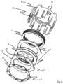
- Figure 3 shows the brake module 1 of the Fig.1 and 2 Exploded view.
- the brake disc 5, the thrust washers 6, and the spring 7 are all arranged in a housing 8, the structure of which is explained below.
- FIG. 4 shows part of the brake module 1 of the Fig.1, 2 and 3 in a further exploded view.
- the brake module 1 comprises, in addition to the housing 8, a cover plate 9.
- the brake disc 5, the two thrust washers 6 and the spring 7 are guided coaxially around the longitudinal axis of the spindle (not shown here).
- the housing 8 is connected to the cover plate 9 by a snap-in connection, whereby the brake disc 5, the two Thrust washers 6 and the spring 7 are held in the housing 8.
- the cover plate 9 has locking recesses 10 into which locking hooks 11 of the housing 8 can engage.
- the structure of the brake module along the longitudinal axis is thus: spring 7, thrust washer 6, brake disc 5, thrust washer 6, cover plate 9. These components are all at least partially enclosed by the housing 8 when assembled. This allows for easy installation of the brake module 1 in the drive system without the risk of losing any part of the brake module 1.
- the housing 8 further comprises a number of, for example, five, housing slots 12 evenly distributed around the longitudinal axis of the spindle nut 4 in the circumferential direction of the housing, with a slot longitudinal axis parallel to the longitudinal axis. Thrust washer projections 13 of the thrust washers 6, directed radially outward from the longitudinal axis, engage in the housing slots 12. This prevents relative rotation of the housing 8 and the thrust washers 6 against each other about the longitudinal axis when the brake disc 5 rotates with the spindle 2 and rubs against the thrust washers 6 during braking.
- the brake disc 5 is annular and has a central recess.
- the central recess has an approximately circular cross-section with at least two, for example four, tooth sections 14 that are evenly distributed around the longitudinal axis in the circumferential direction of the brake disc 5 and separated from one another by recesses 15. This is explained in more detail below. Figure 5 explained in more detail.
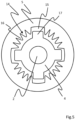
- Figure 5 shows a brake disc 5 according to the invention and a spindle nut 4 in a top view.
- the tooth sections 14 comprise radially inwardly projecting teeth 16.
- the spindle nut 4 comprises spindle nut wings 17 that engage in the recesses 15, and the torque is transmitted between the spindle nut 4 and the brake disc 5 via the contact between the spindle nut wings 17 and the teeth 16. Tilting of the brake disc 5 and the spindle nut 4 is thus less likely than with a positive connection.
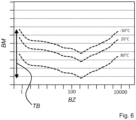
- Figure 6 shows a qualitative representation of the dependence of the braking torque BM of a state-of-the-art braking module on the number of braking cycles BZ and the Temperature.
- the braking cycles are plotted logarithmically, and the development of braking force is shown for three temperatures covering all relevant operating temperatures.
- such a braking module uses thrust washers made of nitrided chrome jet and a brake disc made of sintered steel.
- the braking force of the braking module decreases during the first few hundred braking cycles, before gradually increasing again.
- the braking force varies significantly with temperature, which is illustrated by the double arrow, which indicates the tolerance range TB of the braking system.
- Figure 7 shows a qualitative representation of the dependence of the braking torque BM of a brake module 1 according to the invention on the number of braking cycles BZ and the temperature.
- the braking cycles are again shown logarithmically, and the development of the braking force is plotted for three temperatures that cover all relevant operating temperatures.
- the braking force varies only slightly depending on the braking cycles completed.
- the braking force varies significantly less with temperature, which is illustrated by the double arrow indicating the tolerance range TB of the braking system.
- the braking force is much easier to define and does not have to be selected such that it is significantly too high for a large part of the service life and temperature range, as in the prior art.
- a drive system with such a braking module is also more comfortable to handle, more energy-efficient, and longer-lasting due to the lower braking force in most operating situations.
- the carrier 18 can, for example, be less elastic or more elastic than a brake disc 5 consisting entirely of the friction layer 20. Furthermore, the carrier 18 can be made of a cost-effective plastic.
- the step of coating the carrier 18 may comprise applying a preferably partially elastic adhesive layer 19 to at least one side of the carrier 18, after which the friction layer 20 is applied to the adhesive layer 19.
Landscapes
- Engineering & Computer Science (AREA)
- General Engineering & Computer Science (AREA)
- Mechanical Engineering (AREA)
- Chemical & Material Sciences (AREA)
- Composite Materials (AREA)
- Materials Engineering (AREA)
- Braking Arrangements (AREA)
- Standing Axle, Rod, Or Tube Structures Coupled By Welding, Adhesion, Or Deposition (AREA)
Description
- Die Erfindung betrifft ein Bremsmodul für ein Antriebssystem, insbesondere für Türen, umfassend mindestens eine Anlaufscheibe und mindestens eine Bremsscheibe, wobei die mindestens eine Anlaufscheibe und die mindestens eine Bremsscheibe jeweils mindestens eine Reibfläche aufweisen, die im Bremsbetrieb aneinander reiben. Die Erfindung betrifft außerdem ein Antriebssystem, insbesondere für Türen, umfassend ein derartiges Bremsmodul. Die Erfindung betrifft weiterhin ein Herstellungsverfahren für ein Bremsmodul der oben genannten Art.
- Aus
EP 1 664 470 B1 ist ein Antriebssystem für Verstelleinrichtungen in Kraftfahrzeugen bekannt. Das Antriebssystem umfasst ein Gehäuse, in dem ein Antriebselement der Verstelleinrichtung, ein Scheibenläufermotor mit einer Ankerscheibe und ein Umlaufrädergetriebe angeordnet sind. Das Umlaufrädergetriebe weist ein gehäusefestes Hohlrad mit einer Innenverzahnung, ein mit dem Antriebselement der Verstelleinrichtung verbundenes Abtriebshohlrad mit einer Innenverzahnung und einen radialflexiblen Ring auf, dessen Außenverzahnung partiell mit den Innenverzahnungen des gehäusefesten Hohlrades und des Abtriebshohlrades kämmt und dessen Innenmantelfläche auf Laufrollen abrollt. Das Abtriebshohlrad kann mit einer Schlingfederbremse verbunden sein, wodurch die Selbsthemmung des Antriebssystems erhöht und beispielsweise bei einem Fensterheber verhindert wird, dass durch Herunterdrücken der Fensterscheibe ein unberechtigter Zugang zum Fahrzeuginneren geschaffen wird. -
US 2013/0169087 A1 offenbart ein Antriebssystem zum in Bewegung setzen eines beweglichen Panels eines Fahrzeugs. Das Antriebssystem umfasst in einer Ausführungsform ein mechanisches Bremsmodul, welches eine rohrförmige Bremswelle und eine koaxial darin angeordnete Spiralfeder aufweist. - Im Stand der Technik werden solche Antriebssysteme insbesondere zum elektromechanischen Öffnen und Schließen von Türen, wie beispielsweise von Fahrzeugtüren, verwendet. Das Antriebssystem kann dabei einerseits bei einem manuellen Öffnen, Offenhalten und Schließen der Tür unterstützen und / oder die Tür eigenständig öffnen und schließen. Die Kraft eines Elektromotors wird beispielsweise in einem Linearantrieb über eine Gewindespindel an die Tür übertragen.
- Das Bremsmodul hat dabei mehrere Funktionen. Zum einen ermöglicht es zum Beispiel eine recht schwere Heckklappe eines Fahrzeugs in einer (beliebigen) Winkelposition zu halten und andererseits eine gleichmäßigere Bewegung des Antriebssystems. Weiterhin können Beschädigungen beispielsweise an einer Heckklappe beim Schließen durch zu hohe Beschleunigungskräfte (insbesondere durch eine Handkraft des Benutzers und eine Gewichtskraft der Heckklappe) durch die entgegengesetzte Bremskraft bzw. das resultierende Drehmoment vermieden werden.
- Die Höhe der Bremskraft kann insbesondere durch die Materialwahl und/oder Anzahl der Reibpartner, deren Geometrie sowie gegebenenfalls über die Wahl der Federkraft einer Feder bestimmt werden, die die Anlaufscheibe(n) an eine Bremsscheibe andrückt.
- Üblicherweise drehen sich die Bremsscheibe und die Anlaufscheib(en) relativ zueinander im Bremsbetrieb. Übliche Materialien für die Reibpartner sind gesinterter Stahl für die Bremsscheibe und nitrierter Chromstahl für die Anlaufscheibe.
US 4 828 089 A beschreibt eine Bremse mit einem Reibmaterial aus pyrolytischem Kohlenstoff, das direkt durch eine Flüssigkeit gekühlt wird.JP S63 92840 A - Bei gattungsgemäßen Bremsmodulen besteht das Problem, dass die Bremskraft über die Lebensdauer der Bremsmodule nicht konstant und zusätzlich temperaturabhängig ist.
- Aufgabe der Erfindung ist es daher, ein kostengünstiges Bremsmodul für ein Antriebssystem sowie ein einfach umzusetzendes Herstellungsverfahren dafür bereitzustellen, das eine vorhersagbare Bremskraft für das Antriebssystem bereitstellt und eine Lebensdauer des Antriebssystems erhöht.
- Der Gegenstand der vorliegenden Erfindung stellt ein Bremsmodul für ein Antriebssystem bereit, das diese Aufgabe erfindungsgemäß entsprechend den Merkmalen des Anspruches 1 löst. Ebenso wird die Aufgabe durch ein Antriebssystem gemäß den Merkmalen des Anspruchs 8 und ein Verfahren entsprechend den Merkmalen des Anspruches 9 gelöst. Vorteilhafte Ausgestaltungen ergeben sich aus den abhängigen Ansprüchen.
- Ein erfindungsgemäßes Bremsmodul für ein Antriebssystem, insbesondere für Türen, umfasst mindestens eine Anlaufscheibe und mindestens eine Bremsscheibe, wobei die mindestens eine Anlaufscheibe und die mindestens eine Bremsscheibe jeweils mindestens eine Reibfläche aufweisen, die im Bremsbetrieb aneinander reiben.
- Unter dem Begriff "Tür" wird im Sinne der Erfindung ein Bauteil zum zumindest teilweise Verschließen einer Öffnung eines Bauwerks, eines Geräts oder eines Fahrzeugs verstanden. Insbesondere kann die "Tür" eine Fahrzeugtür, beispielsweise eine Zugangstür für Passagiere des Fahrzeugs, eine Motorhaube, eine Gepäckraumklappe, eine Laderaumtür oder eine Heckklappe sein. Ein "Fahrzeug" im Sinne der Erfindung kann beispielsweise ein Landfahrzeug, ein Wasserfahrzeug oder ein Luftfahrzeug, insbesondere ein Automobil sein. Das erfindungsgemäße Bremsmodul ist besonders für ein Antriebsmodul für Fahrzeugtüren geeignet, weil dort, beispielsweise aus Gründen der Betriebssicherheit eine konstante und vorhersagbare Bremskraft besonders wichtig ist. Außerdem sind Antriebssysteme für Fahrzeugtüren oft so verbaut, dass sie nur schwierig austauschbar sind, sodass eine lange Lebensdauer besonders wichtig ist.
- Mindestens eine der Reibflächen der Bremsscheibe ist von einer Reibschicht zum Schutz der Bremsscheibe und/oder Anlaufscheibe vor Verschleiß gebildet, wobei zumindest die Reibschicht Fasern und Kohlenstoff, nämlich ein Karbonfasergewebe, umfasst. Dadurch lässt sich eine über die Lebensdauer des Bremsmoduls konstantere Bremskraft, eine geringere Temperaturabhängigkeit der Bremskraft und eine höhere Lebensdauer des Bremsmoduls erzielen. Daher kann die Bremskraft auch besser an die jeweilige Anwendung angepasst werden und es ist ein deutlich geringerer Toleranzausgleich notwendig. Im Falle der Verwendung für eine Heckklappe eines Fahrzeuges ermöglicht dies zum Beispiel für mittlere Temperaturen des Bremssystems (ca. 20 °C) eine geringere Bremskraft und damit ein leichteres Betätigen aus jeder Ausgangsposition in jede andere Endposition der Tür, also insbesondere einem Öffnen oder einem Schließen, der Heckklappe. Die Endposition kann eine beliebige Zwischenposition zwischen einer maximalen Öffnungsposition und einer Verschlussposition sein. Gleichzeitig wird die Funktionalität bei höheren Temperaturen oder zu Beginn der Verwendung des Antriebssystems nicht eingeschränkt. Insbesondere wird das Antriebssystem über die Lebensdauer und über veränderliche Betriebsparameter (wie zum Beispiel die Temperatur des Bremsmoduls) zuverlässiger und gleichzeitig leichtgängiger, weil eine Sicherheitstoleranz zwischen einer minimalen Bremskraft, um die Tür in jeder Zwischenposition halten zu können, und einer Handkraft zur Positionsveränderung kleiner ausgelegt werden kann.
- Die konstantere und besser vorhersagbare Bremskraft im Vergleich zu einer gesinterten Bremsscheibe lässt sich zum Teil durch die gleichmäßigere Oberfläche einer erfindungsgemäßen Bremsscheibe erklären. Gesinterte Bremsscheiben weisen durch den Sinterprozess zu Beginn abgerundete Randbereiche und damit eine verringerte effektive Reibfläche auf. Eine Bremsscheibe mit einer erfindungsgemäßen Reibschicht zum Schutz der Bremsscheibe vor Verschleiß hat hingegen von vornherein eine flachere Reibfläche und die effektive Reibfläche verändert sich im Laufe des Betriebs des Bremsmoduls nicht.
- Weitere Ausgestaltungen werden beispielhaft anhand von Reibschichten, die Reibflächen der Bremsscheibe bilden, beschrieben. Im Sinne der Erfindung lassen sich diese Ausgestaltungen zusätzlich auch auf Reibschichten, die Reibflächen der Anlaufscheibe bilden, übertragen.
- Vorzugsweise ist jede Reibfläche der Bremsscheibe von jeweils einer erfindungsgemäßen Reibschicht gebildet. Dadurch treten die vorgenannten Wirkungen der Reibschichten besonders deutlich auf.
- Ein Teil der Bremsscheibe, wie beispielsweise eine oder mehrere Schichten der Bremsscheibe, ist von der Reibschicht gebildet. Die Reibschicht der Bremsscheibe kann also eine oder mehrerer Oberflächenschichten (beispielsweise Reibschichten) der Bremsscheibe bilden.
- Die Reibschicht umfasst Karbonfasern, nämlich ein Karbonfasergewebe. Karbonfasern, insbesondere in einem Karbonfasergewebe, können bei geringem Gewicht sehr hohen mechanischen Belastungen standhalten, insbesondere wenn jeweils eine hohe Anzahl von Fasern zu einem Filamentgarn zusammengefasst ist. Dadurch wird eine hohe Zuverlässigkeit des Bremsmoduls bei gleichzeitig geringem Gewicht erzielt.
- Die Reibschicht kann einen faserverstärkten, bevorzugt glasfaserverstärkten und/oder karbonfaserverstärkten, Kunststoff umfassen. In Form eines faserverstärkten Kunststoffs können die überragenden mechanischen Eigenschaften der Fasern vorteilhaft mit der einfachen Verarbeitung eines Kunststoffs kombiniert werden, sodass sich ein zuverlässiges, leichtes und kostengünstig herzustellendes Bremsmodul ergibt.
- Die Reibschicht kann eine, bevorzugt metallhaltige und/oder wasserstoffhaltige, amorphe Kohlenstoffschicht umfassen. Amorphe Kohlenstoffschichten zeichnen sich durch eine hohe Verschleißbeständigkeit aus. Durch Dotieren von wasserstoffhaltigen amorphen Kohlenstoffschichten (a-C:H) mit Metallen bildet sich ein Verbund aus einer a-C:H Matrix und Metallkarbiden. Schichten aus diesem Material besitzen hohe Verschleißfestigkeiten, geringe Reibkoeffizienten sowie bessere Haftung der Schichten. Durch Veränderung des Metallgehaltes lassen sich die Materialeigenschaften stark beeinflussen und somit auf die Anforderungen des Antriebssystems anpassen.
- Das Bremsmodul kann eine Feder umfassen, die die Bremsscheibe durch eine Federkraft an die mindestens eine Anlaufscheibe andrückt. Die Feder ist vorzugsweise eine Wellenfeder, wodurch eine gleichmäßige Federkraft erzielt und das Bremsmodul stabilisiert wird. Die Feder kann auf einer der Bremsscheibe gegenüberliegenden Seite einer Anlaufscheibe angeordnet sein und die Anlaufscheibe an die Bremsscheibe andrücken.
- Das Bremsmodul kann je eine Anlaufscheibe auf zwei gegenüberliegenden Seiten der Bremsscheibe umfassen, wobei die Bremsscheibe je eine jeder der Anlaufscheiben zugewandte Reibfläche mit je einer erfindungsgemäßen Reibschicht umfasst. Durch die Verwendung von zwei Anlaufscheiben auf beiden Seiten der Bremsscheibe lässt sich eine höhere Lebensdauer und höhere Bremskraft erzielen, ohne die Abmessungen des Bremsmoduls wesentlich zu erhöhen.
- Die Bremsscheibe umfasst einen Träger, aus Gewichts-, Kosten- und gleichzeitig Stabilitätsgründen insbesondere aus Kunststoff, und mindestens eine mit dem Träger verbundene Reibschicht, vorzugsweise zwei auf gegenüberliegenden Seiten des Trägers mit dem Träger verbundene Reibschichten. Erfindungsgemäß umfasst die Bremsscheibe mehrere Schichten, wodurch sich bessere Gesamteigenschaften der Bremsscheibe erzielen lassen. Der Träger kann beispielsweise weniger elastisch oder elastischer sein als eine komplett aus einer Reibschicht bestehende Bremsscheibe (je nach Anforderung der Nutzungsspezifikationen und des Antriebsystems, in dem die Bremsscheibe eingesetzt wird). Außerdem lässt sich das thermische Ausdehnungsverhalten der Bremsscheibe bei Verwendung zweier oder mehrerer verschiedener Materialien besser auf das thermische Ausdehnungsverhalten der Anlaufscheibe(n) abstimmen und so die Temperaturabhängigkeit des Bremsmoments reduzieren. Weiterhin kann der Träger aus einem kostengünstigen Material, beispielsweise einem Kunststoff, bestehen, wodurch sich Gesamtkosten der Bremsscheibe reduzieren lassen.
- Die mindestens eine Reibschicht kann stoffschlüssig, vorzugsweise mit einem, vorzugsweise teilelastischen, Klebstoff an dem Träger befestigt sein. Eine stoffschlüssige Verbindung, beispielsweise durch einen Klebstoff oder durch Beschichten des Trägers mit einer amorphen Kohlenstoffschicht, sorgt für eine besonders langzeitstabile und zuverlässige Verbindung der Reibschicht mit dem Träger. Der teilelastische Kleber kann beispielsweise unterschiedliche thermische Ausdehnungskoeffizienten der Reibschicht(en) und des Trägers ausgleichen. Weiterhin erlaubt der teilelastische Kleber eine verbesserte Vibrationsdämpfung.
- Die mindestens eine Anlaufscheibe besteht aus Stahl, nämlich aus, erfindungsgemäß nicht-nitriertem, Chrom-5-Stahl. Es hat sich herausgestellt, dass eine Anlaufscheibe aus nicht-nitriertem Chrom-5-Stahl zwar eine geringere Lebensdauer aufweist als eine Anlaufscheibe aus nitriertem Chrom-5-Stahl, sich die Vibrations- und Geräuschentwicklung bei Reibung mit einer Bremsscheibe aus faserverstärktem Kunststoff aber deutlich gegenüber nitriertem Chrom-5-Stahl verringert. Ein solches erfindungsgemäßes Bremsmodul mit Anlaufscheibe(n) aus nicht-nitriertem Chrom-5-Stahl weist insgesamt dennoch eine vergleichbare oder sogar höhere Lebensdauer als ein Bremsmodul des Standes der Technik auf.
- Die Bremsscheibe kann ringförmig sein und insbesondere eine zentrale Ausnehmung aufweisen, wobei die zentrale Ausnehmung vorzugsweise näherungsweise kreisförmig ist, insbesondere mit mindestens zwei durch eine Anzahl von, beispielsweise einer, zwei, drei, vier, fünf, sechs oder sieben, Aussparungen voneinander getrennten Zahnabschnitten, wobei die Zahnabschnitte vorzugsweise radial nach innen vorspringende Zähne umfassen. Eine solche Ausgestaltung erlaubt eine flexiblere Verbindung der Bremsscheibe, beispielsweise mit einer Antriebswelle, insbesondere einer Gewindespindel, des Antriebssystems. Ein Verkanten der Bremsscheibe und der Spindelmutter wird dadurch unwahrscheinlich. Somit ist es auch leichter, das Bremsmodul erst spät in einem Produktionsprozess eines Antriebssystems zu installieren und Vibrationsschäden bei der Montage zu vermeiden bzw. es zu entfernen, falls das Bremsmodul defekt ist. Ein näherungsweise kreisförmiger Querschnitt der Ausnehmung kann beispielsweise bedeuten, dass der Querschnitt bis auf die radial nach innen vorstehenden Zahnabschnitte kreisförmig ist. Die Aussparungen sind vorteilhafterweise in Umfangsrichtung der Bremsscheibe gleichmäßig, also mit konstantem Winkelabstand voneinander, um die Ausnehmung verteilt, um eine gleichmäßige Belastung der Bremsscheibe und somit eine hohe Lebensdauer derselben sicherzustellen.
- Die Bremsscheibe und/oder die Anlaufscheibe können in einer Reibfläche eine Anzahl von Vertiefungen zur Aufnahme eines Schmiermittels aufweisen. Die Vertiefungen können als Reservoir für ein auf die Reibpartner, also auf Chrom-5-Stahl und eine kohlenstoffhaltige Reibschicht, abgestimmtes Schmiermittel dienen und damit die Lebensdauer des Bremsmoduls erhöhen, ohne dass große Mengen des Schmiermittels notwendig sind.
- Das Bremsmodul kann ein Gehäuse umfassen, in dem die Bremsscheibe und die mindestens eine Anlaufscheibe, vorzugsweise koaxial um eine zentrale Achse, insbesondere die Längsachse einer Antriebswelle, insbesondere einer Gewindespindel, des Antriebssystems, geführt sind, wobei das Bremsmodul vorzugsweise eine Deckscheibe umfasst, die, vorzugsweise durch eine Rastverbindung, mit dem Gehäuse derart verbunden ist, dass die Bremsscheibe und die mindestens eine Anlaufscheibe im Gehäuse gehalten sind. Die Deckscheibe kann beispielsweise Rastausnehmungen aufweisen, in die Rasthaken des Gehäuses eingreifen können. Vorteilhafterweise kann die Rastverbindung so ausgestaltet sein, dass die Deckscheibe nicht zerstörungsfrei von dem Gehäuse getrennt werden kann. Dadurch werden in dem Gehäuse angeordnete Komponenten vor Manipulationen geschützt.
- Vorzugsweise ist der Aufbau des Bremsmoduls entlang der Längsachse: Feder, Anlaufscheibe, Bremsscheibe, Anlaufscheibe, Deckscheibe. Vorzugsweise sind diese Komponenten alle zumindest teilweise vom Gehäuse umgeben. Damit lässt sich eine einfache Montage des Bremsmoduls im Antriebssystem erreichen, ohne dass die Gefahr besteht, einen Teil des Bremsmoduls zu verlieren.
- Das Gehäuse kann eine Anzahl von, beispielsweise einem, zwei, drei, vier, fünf, sechs oder sieben, Gehäuseschlitzen umfassen, deren Schlitzlängsachse vorteilhafterweise parallel zu der Längsachse der Antriebswelle ausgerichtet ist. Ferner kann zumindest eine Anlaufscheibe radial von der Längsachse nach außen gerichtete Anlaufscheibenvorsprünge aufweisen, die komplementär zu den Gehäuseschlitzen geformt sind, sodass die Gehäuseschlitze und die Anlaufscheibenvorsprünge gegen eine Verdrehung der Anlaufscheibe gegenüber dem Gehäuse um die Längsachse formschlüssig zusammenwirken. Dadurch wird verhindert, dass sich die Anlaufscheibe bei einem Bremsvorgang mit der Bremsscheibe mitdreht, was die Bremswirkung verringern oder sogar aufheben könnte. Durch eine Ausrichtung der Schlitzlängsachse parallel zu der Längsachse der Antriebswelle kann die Anlaufscheibe bei einer Montage des Bremsmoduls einfach entlang der Längsachse in das Gehäuse eingeführt werden. Vorteilhafterweise sind die Gehäuseschlitze in Umfangsrichtung des Gehäuses um die Längsachse gleichmäßig, also mit kontantem Winkelabstand voneinander, verteilt. Dadurch wird das Gehäuse gleichmäßig belastet, was seine Lebensdauer erhöht.
- Die erfindungsgemäße Aufgabe wird auch durch ein Antriebssystem, insbesondere für eine Tür, umfassend ein Bremsmodul nach einer der vorstehenden Ausführungsformen gelöst.
- Die erfindungsgemäße Aufgabe wird auch durch ein Herstellungsverfahren für ein erfindungsgemäßes Bremsmodul gelöst, das Bremsmodul umfassend mindestens eine Anlaufscheibe und mindestens eine Bremsscheibe, wobei die mindestens eine Anlaufscheibe und die mindestens eine Bremsscheibe jeweils mindestens eine Reibfläche aufweisen, die im Bremsbetrieb aneinander reiben, wobei das Verfahren die folgenden Schritte umfasst:
- a. Bereitstellen eines, insbesondere scheibenförmigen, Trägers,
- b. Bereitstellen mindestens eines Anlaufscheibenrohlings für die Anlaufscheibe aus nicht-nitriertem Chrom-5-Stahl,
- b. Beschichten des Trägers auf mindestens einer Seite mit einer Fasern und Kohlenstoff, nämlich ein Karbonfasergewebe, umfassenden Reibschicht zum Verschleißschutz, um die Bremsscheibe zu formen.
- Das Material mindestens einer Reibschicht der Bremsscheibe umfasst somit Fasern und Kohlenstoff, nämlich ein Karbonfasergewebe, wodurch sich eine zeitlich konstantere Bremskraft, eine geringere Temperaturabhängigkeit der Bremskraft und eine höhere Lebensdauer des Bremsmoduls erzielen lässt. Dadurch kann die Bremskraft besser an die jeweilige Anwendung angepasst werden und es ist ein deutlich geringerer Toleranzausgleich notwendig. Der Träger kann beispielsweise elastischer oder weniger elastisch sein als eine komplett aus der Reibschicht bestehende Bremsscheibe. Außerdem lässt sich das thermische Ausdehnungsverhalten der Bremsscheibe bei Verwendung mehrerer, insbesondere zweier, verschiedener Materialien besser auf das thermische Ausdehnungsverhalten der Anlaufscheibe(n) abstimmen und so die Temperaturabhängigkeit der Bremskraft reduzieren. Weiterhin kann der Träger aus einem kostengünstigen Kunststoff bestehen, wodurch sich Gesamtkosten der Bremsscheibe reduzieren lassen.
- Vorzugsweise wird der Träger auf zwei gegenüberliegenden Seite mit einer Reibschicht beschichtet um die Bremsscheibe zu formen.
- Der Schritt des Beschichtens des Trägers kann ein Auftragen einer, vorzugsweise teilelastischen, Klebstoffschicht auf mindestens einer Seite des Trägers umfassen, wonach die Reibschicht auf die Klebstoffschicht aufgetragen wird. Die Klebstoffschicht kann beispielsweise unterschiedliche thermische Ausdehnungskoeffizienten der Reibschicht(en) und des Trägers ausgleichen. Weiterhin erlaubt die Klebstoffschicht eine verbesserte Vibrationsdämpfung.
- Der Klebstoff kann isobar und variotherm ausgehärtet werden. Dadurch wird eine dauerhafte Verbindung zwischen Träger und Reibschicht erzielt.
- Das Herstellungsverfahren kann außerdem die folgenden Schritte umfassen:
- a. Bereitstellen mindestens eines scheibenförmigen Anlaufscheibenrohlings, der aus Stahl, nämlich aus, erfindungsgemäß nicht-nitriertem, Chrom-5-Stahl besteht, und vorzugsweise
- b. Polieren des Anlaufscheibenrohlings, vorzugsweise durch Kugelpolieren, um die Anlaufscheibe zu formen.
- Es hat sich herausgestellt, dass durch Polieren und insbesondere Kugelpolieren eine besonders gleichmäßige Reibfläche erzielt werden kann, die weniger richtungsabhängige Artefakte aufweist. Auch dadurch kann der Effekt vermindert werden, dass sich die Anlaufscheibe erst im Betrieb "flachbremst" und die Bremskraft anfänglich, beispielsweise in den ersten einigen hundert Bremszyklen stark variiert. Weiterhin führt eine gleichmäßige Reibfläche zu weniger Vibrationen bei einem Bremsvorgang und somit zu einer geringen Geräuschentwicklung.
- Der mindestens eine Anlaufscheibenrohling kann, insbesondere zusätzlich zu dem Polieren, beispielsweise vor dem Polieren, entgratet werden. So lässt sich eine noch gleichmäßigere Reibfläche der Anlaufscheibe erzielen.
- Weitere Vorteile, Ziele und Eigenschaften vorliegender Erfindung werden anhand nachfolgender Beschreibung und anliegender Zeichnungen erläutert, in welchen beispielhaft erfindungsgemäße Bremsmodule und Herstellungsverfahren dargestellt sind. Bauteile der Vorrichtungen, welche in den Figuren wenigstens im Wesentlichen hinsichtlich ihrer Funktion übereinstimmen, können hierbei mit gleichen Bezugsziffern gekennzeichnet sein, wobei diese Bauteile nicht in allen Figuren beziffert und erläutert sein müssen.
-
- Fig. 1
- ein erfindungsgemäßes Bremsmodul in Außenansicht;
- Fig. 2
- das Bremsmodul der
Fig.1 in Schnittansicht; - Fig. 3
- das Bremsmodul der
Fig.1 und 2 in Explosionsdarstellung; - Fig. 4
- einen Teil des Bremsmoduls der
Fig.1, 2 und3 in einer weiteren Explosionsdarstellung; - Fig. 5
- eine erfindungsgemäße Bremsscheibe und eine Spindelmutter.
- Fig. 6
- eine qualitative Darstellung der Abhängigkeit des Bremsdrehmoments eines Bremsmoduls des Standes der Technik in Abhängigkeit von der Anzahl der Bremszyklen und der Temperatur;
- Fig. 7
- eine qualitative Darstellung der Abhängigkeit des Bremsdrehmoments eines erfindungsgemäßen Bremsmoduls in Abhängigkeit von der Anzahl der Bremszyklen und der Temperatur;
- Fig. 8
- eine schematische Ablaufdarstellung eines erfindungsgemäßen Herstellungsverfahrens.
-
Figur 1 zeigt ein erfindungsgemäßes Bremsmodul 1 in Außenansicht. Das Bremsmodul 1 ist hier mit einer Spindel 2 eines Antriebssystems verbunden. Das Bremsmodul 1 umfasst ein zylinderförmiges Außengehäuse 3. -
Figur 2 zeigt das Bremsmodul 1 derFig.1 in Schnittansicht. Das Antriebssystem umfasst eine mit der Spindel 2 verbundene Spindelmutter 4. Die Spindelmutter 4 greift im Bremsbetrieb in eine radial zur Längsachse der Spindel außerhalb die Spindelmutter 4 angeordnete Bremsscheibe 5 des Bremsmoduls 1 ein. Die Bremsscheibe 5 umfasst mindestens zwei Reibflächen die an angrenzenden Reibflächen von zwei Anlaufscheiben 6 im Bremsbetrieb infolge relativer Rotation der Bremsscheibe 5 gegenüber den Anlaufscheiben 6 um die Längsachse reiben. Dadurch wird ein Bremsdrehmoment auf die Spindel 2 des Antriebssystems ausgeübt. Eine Feder 7 übt eine Federkraft entlang der Längsachse auf eine der Anlaufscheiben 6 aus, wodurch die Bremsscheibe 5 und die Anlaufscheiben 6 aneinander angepresst werden, um sie im Reibkontakt zu halten. Die Stärke der Federkraft ist ein Parameter, über den sich die Größe der Bremskraft festlegen lässt. In dieser Ausführungsform ist die Feder 7 eine Wellenfeder. -
Figur 3 zeigt das Bremsmodul 1 derFig.1 und 2 in Explosionsdarstellung. Die Bremsscheibe 5, die Anlaufscheiben 6 und die Feder 7 sind hier alle in einem Gehäuse 8 angeordnet, dessen Aufbau im Folgenden erklärt wird. -
Figur 4 zeigt einen Teil des Bremsmoduls 1 derFig.1, 2 und3 in einer weiteren Explosionsdarstellung. Das Bremsmodul 1 umfasst zusätzlich zum Gehäuse 8 eine Deckscheibe 9. Im Gehäuse 8 sind die Bremsscheibe 5, die zwei Anlaufscheiben 6 und die Feder 7 koaxial um die Längsachse der Spindel (hier nicht dargestellt) geführt. Das Gehäuse 8 ist durch eine Rastverbindung mit der Deckscheibe 9 verbunden, wodurch die Bremsscheibe 5, die zwei Anlaufscheiben 6 und die Feder 7 im Gehäuse 8 gehalten werden. Die Deckscheibe 9 weist Rastausnehmungen 10 auf, in die Rasthaken 11 des Gehäuses 8 eingreifen können. Der Aufbau des Bremsmoduls entlang der Längsachse ist somit: Feder 7, Anlaufscheibe 6, Bremsscheibe 5, Anlaufscheibe 6, Deckscheibe 9. Diese Komponenten sind alle im zusammengesetzten Zustand zumindest teilweise vom Gehäuse 8 umgeben. Damit lässt sich eine einfache Montage des Bremsmoduls 1 im Antriebssystem erreichen, ohne dass die Gefahr besteht, einen Teil des Bremsmoduls 1 zu verlieren. - Das Gehäuse 8 umfasst weiterhin eine Anzahl von, beispielsweise fünf, um die Längsachse der Spindelmutter 4 in Umfangsrichtung des Gehäuses gleichmäßig verteilte Gehäuseschlitzen 12 mit einer Schlitzlängsachse parallel zu der Längsachse. In die Gehäuseschlitze 12 greifen radial von der Längsachse nach außen gerichtete Anlaufscheibenvorsprünge 13 der Anlaufscheiben 6 ein. Dadurch wird eine relative Rotation des Gehäuses 8 und der Anlaufscheiben 6 gegeneinander um die Längsachse verhindert, wenn sich die Bremsscheibe 5 mit der Spindel 2 dreht und im Bremsbetrieb an den Anlaufscheiben 6 reibt.
- Die Bremsscheibe 5 ist ringförmig und weist eine zentrale Ausnehmung auf. Die zentrale Ausnehmung hat einen näherungsweise kreisförmigen Querschnitt mit mindestens zwei, beispielsweise vier, in Umfangsrichtung der Bremsscheibe 5 um die Längsachse gleichmäßig verteilten Zahnabschnitten 14, die durch Aussparungen 15 voneinander getrennt sind. Dies wird anhand der folgenden
Figur 5 detaillierter erklärt. -
Figur 5 zeigt eine erfindungsgemäße Bremsscheibe 5 und eine Spindelmutter 4 in Aufsicht. Die Zahnabschnitte 14 umfassen radial nach innen vorspringende Zähne 16. Eine solche Ausgestaltung erlaubt eine flexible Verbindung der Bremsscheibe 5 mit der Spindelmutter 4 des Antriebssystems. Die Spindelmutter 4 umfasst Spindelmutterflügel 17, die in die Aussparungen 15 eingreifen, und die Übertragung des Drehmoments zwischen der Spindelmutter 4 und der Bremsscheibe 5 erfolgt über den Kontakt zwischen den Spindelmutterflügeln 17 und den Zähnen 16. Ein Verkanten der Bremsscheibe 5 und der Spindelmutter 4 wird dadurch unwahrscheinlicher als bei einer formschlüssigen Verbindung. Dies erleichtert es, das Bremsmodul 1 erst spät im Produktionsprozess eines Antriebssystems zu installieren, Vibrationsschäden durch einen späteren Montagezeitpunkt zu vermeiden und das Bremsmodul 1 zu ersetzen, wenn das Bremsmodul 1 defekt ist, da das Bremsmodul 1 einfacher auf die Spindelmutter 4 aufgesetzt werden kann. -
Figur 6 zeigt eine qualitative Darstellung der Abhängigkeit des Bremsdrehmoments BM eines Bremsmoduls des Standes der Technik von der Anzahl der Bremszyklen BZ und der Temperatur. Die Bremszyklen sind logarithmisch dargestellt und die Entwicklung der Bremskraft ist für drei Temperaturen aufgetragen, die alle relevanten Betriebstemperaturen abdecken. Ein solches Bremsmodul verwendet beispielsweise Anlaufscheiben aus nitriertem Chromstrahl und eine Bremsscheibe aus gesintertem Stahl. Wie erkennbar ist, verringert sich in den ersten einigen hundert Bremszyklen die Bremskraft des Bremsmoduls, um dann nach und nach wieder anzusteigen. Weiterhin ist erkennbar, dass die Bremskraft stark mit der Temperatur variiert, was durch den Doppelpfeil verdeutlicht ist, der den Toleranzbereich TB des Bremssystems anzeigt. -
Figur 7 zeigt eine qualitative Darstellung der Abhängigkeit des Bremsdrehmoments BM eines erfindungsgemäßen Bremsmoduls 1 von der Anzahl der Bremszyklen BZ und der Temperatur. Die Bremszyklen sind erneut logarithmisch dargestellt und die Entwicklung der Bremskraft ist für drei Temperaturen aufgetragen, die alle relevanten Betriebstemperaturen abdecken. Wie erkennbar ist, variiert die Bremskraft nur leicht in Abhängigkeit der abgelaufenen Bremszyklen. Weiterhin ist erkennbar, dass die Bremskraft deutlich weniger mit der Temperatur variiert, was durch den Doppelpfeil verdeutlicht ist, der den Toleranzbereich TB des Bremssystems anzeigt. Somit ist die Bremskraft deutlich besser definierbar und muss nicht wie im Stand der Technik so gewählt werden, dass sie für einen Großteil der Lebensdauer und des Temperaturbereichs deutlich zu groß ist. Dadurch wird der Abrieb der Bremsscheibe und der Anlaufscheiben im Mittel verringert, was zum Teil die erhöhte Lebensdauer des Bremssystems erklärt. Ein Antriebssystem mit einem solchen Bremsmodul ist durch die in den meisten Betriebssituationen geringere Bremskraft auch komfortabler in der Handhabung sowie energieeffizienter und langlebiger. -
Figur 8 zeigt eine schematische Ablaufdarstellung eines erfindungsgemäßen Herstellungsverfahrens. Das erfindungsgemäße das Herstellungsverfahren umfasst hier die folgenden Schritte: - a. Bereitstellen eines, beispielsweise scheibenförmigen, Trägers 18, beispielsweise aus Kunststoff,
- optional: a1. Beschichten des Trägers 18 auf mindestens einer Seite (hier auf zwei Seiten) mit einer Klebstoffschicht 19,
- c. Beschichten des Trägers 18 (bzw. optional der Klebstoffschicht 19) auf mindestens einer Seite (hier auf zwei Seiten) mit einer Fasern und Kohlenstoff, nämlich ein Karbonfasergewebe, umfassenden Reibschicht 20, um die Bremsscheibe 5 zu formen.
- Der Träger 18 kann beispielsweise weniger elastisch oder elastischer sein als eine komplett aus der Reibschicht 20 bestehende Bremsscheibe 5. Weiterhin kann der Träger 18 aus einem kostengünstigen Kunststoff bestehen.
- Der Schritt des Beschichtens des Trägers 18 kann ein Auftragen einer, vorzugsweise teilelastischen, Klebstoffschicht 19 auf mindestens einer Seite des Trägers 18 umfassen, wonach die Reibschicht 20 auf die Klebstoffschicht 19 aufgetragen wird.
-
- 1
- Bremsmodul
- 2
- Spindel
- 3
- Außengehäuse
- 4
- Spindelmutter
- 5
- Bremsscheibe
- 6
- Anlaufscheibe
- 7
- Feder
- 8
- Gehäuse
- 9
- Deckscheibe
- 10
- Rastausnehmungen
- 11
- Rasthaken
- 12
- Gehäuseschlitz
- 13
- Anlaufscheibenvorsprung
- 14
- Zahnabschnitt
- 15
- Aussparung
- 16
- Zahn
- 17
- Spindelmutterflüge
- 18
- Träger
- 19
- Klebstoffschicht
- 20
- Reibschicht
- BM
- Bremsdrehmoment
- BZ
- Anzahl Bremszyklen
- TB
- Toleranzbereich
Claims (11)
- Bremsmodul (1) für ein Antriebssystem, insbesondere für Türen, umfassend mindestens eine Anlaufscheibe (6) und mindestens eine Bremsscheibe (5),a) wobei die mindestens eine Anlaufscheibe (6) und die mindestens eine Bremsscheibe (5) jeweils mindestens eine Reibfläche aufweisen, die im Bremsbetrieb aneinander reiben,b) wobei mindestens eine der Reibflächen der Bremsscheibe (5) von einer Reibschicht (20) zum Schutz der Bremsscheibe (5) und/oder Anlaufscheibe (6) vor Verschleiß gebildet ist, wobeic) die Bremsscheibe (5) einen Träger (18) und mindestens eine mit dem Träger (18) verbundene Reibschicht (20) umfasst,d) wobei die Reibschicht (20) ein Karbonfasergewebe umfasst, dadurch gekennzeichnet, dasse) die Anlaufscheibe (6) aus nicht-nitriertem Chrom-5-Stahl besteht.
- Bremsmodul (1) nach Anspruch 1,
dadurch gekennzeichnet, dass
das Bremsmodul (1) je eine Anlaufscheibe (6) auf zwei gegenüberliegenden Seiten der Bremsscheibe (5) umfasst, wobei die Bremsscheibe (5) je eine jeder der Anlaufscheiben (6) zugewandte Reibfläche mit je einer Reibschicht (20) umfasst. - Bremsmodul (1) nach einem der Ansprüche 1 bis 2,
dadurch gekennzeichnet, dass
die Bremsscheibe (5)a) einen Träger (18) aus einem Kunststoff und/oderb) zwei auf gegenüberliegenden Seiten des Trägers (18) mit dem Träger (18) verbundene Reibschichten (20) umfasst. - Bremsmodul (1) nach einem der Ansprüche 1 bis 3,
dadurch gekennzeichnet, dass
die mindestens eine Reibschicht (20) stoffschlüssig, bevorzugt mit einer, vorzugsweise teilelastischen, Klebstoffschicht (19) an dem Träger (18) befestigt ist. - Bremsmodul (1) nach einem der Ansprüche 1 bis 4,
dadurch gekennzeichnet, dass
die Bremsscheibe (5) ringförmig ist und bevorzugt eine zentrale Ausnehmung aufweist, wobei die zentrale Ausnehmung einen näherungsweise kreisförmigen Querschnitt mit mindestens zwei durch Aussparungen (15) getrennten Zahnabschnitten (14) aufweist. - Bremsmodul (1) nach einem der Ansprüche 1 bis 5,
dadurch gekennzeichnet, dass
die Bremsscheibe (5) und / oder die Anlaufscheibe (6) in einer Reibfläche eine Anzahl von Vertiefungen zur Aufnahme eines Schmiermittels aufweist. - Bremsmodul (1) nach einem der Ansprüche 1 bis 6,
dadurch gekennzeichnet, dass
das Bremsmodul (1) ein Gehäuse (8) umfasst, in dem die Bremsscheibe (5) und die mindestens eine Anlaufscheibe (6), bevorzugt koaxial um eine zentrale Achse, geführt sind, wobei das Bremsmodul (1) bevorzugt eine Deckscheibe (9) umfasst, die besonders bevorzugt durch eine Rastverbindung, mit dem Gehäuse (9) derart verbunden ist, dass die Bremsscheibe (5) und die mindestens eine Anlaufscheibe (6) im Gehäuse (8) gehalten sind. - Antriebssystem, insbesondere für eine Tür, umfassend ein Bremsmodul (1) nach einem der vorstehenden Ansprüche.
- Herstellungsverfahren für ein Bremsmodul (1) nach einem der Ansprüche 1 bis 7 umfassend mindestens eine Anlaufscheibe (6) und mindestens eine Bremsscheibe (5), wobei die mindestens eine Anlaufscheibe (6) und die mindestens eine Bremsscheibe (5) jeweils mindestens eine Reibfläche aufweisen, die im Bremsbetrieb aneinander reiben,
gekennzeichnet durch folgende Schritte:a. Bereitstellen eines Trägers (18),b. Bereitstellen mindestens eines Anlaufscheibenrohlings für die Anlaufscheibe (6) aus nicht-nitriertem Chrom-5-Stahl, undc. Beschichten des Trägers (18) auf mindestens einer Seite mit einer ein Karbonfasergewebe umfassenden Reibschicht (20) zum Verschleißschutz, um die Bremsscheibe (5) zu formen. - Herstellungsverfahren nach Anspruch 9,
dadurch gekennzeichnet, dass
der Schritt des Beschichtens des Trägers (18) ein Auftragen einer, vorzugsweise teilelastischen, Klebstoffschicht (19) auf mindestens einer Seite des Trägers (18) umfasst, wonach die Reibschicht (20) auf die Klebstoffschicht (19) aufgetragen wird. - Herstellungsverfahren nach einem der Ansprüche 9 bis 10,gekennzeichnet durch folgende Schritte:Polieren und/oder Entgraten des Anlaufscheibenrohlings, um die Anlaufscheibe (6) zu formen.
Applications Claiming Priority (1)
| Application Number | Priority Date | Filing Date | Title |
|---|---|---|---|
| DE102018109569.4A DE102018109569B4 (de) | 2018-04-20 | 2018-04-20 | Bremsmodul für ein antriebssystem, antriebssystem und herstellungsverfahren für ein bremsmodul |
Publications (2)
| Publication Number | Publication Date |
|---|---|
| EP3561336A1 EP3561336A1 (de) | 2019-10-30 |
| EP3561336B1 true EP3561336B1 (de) | 2025-06-04 |
Family
ID=66182442
Family Applications (1)
| Application Number | Title | Priority Date | Filing Date |
|---|---|---|---|
| EP19169291.2A Active EP3561336B1 (de) | 2018-04-20 | 2019-04-15 | Bremsmodul für ein antriebssystem, antriebssystem und herstellungsverfahren für ein bremsmodul |
Country Status (6)
| Country | Link |
|---|---|
| US (1) | US11248405B2 (de) |
| EP (1) | EP3561336B1 (de) |
| JP (1) | JP7291526B2 (de) |
| KR (1) | KR102703979B1 (de) |
| CN (1) | CN110397359B (de) |
| DE (1) | DE102018109569B4 (de) |
Families Citing this family (9)
| Publication number | Priority date | Publication date | Assignee | Title |
|---|---|---|---|---|
| DE102018124895A1 (de) * | 2017-11-03 | 2019-05-09 | Stabilus Gmbh | Modulares, motorisiertes Antriebssystem, Modul, Verwendung und Fertigungsverfahren dafür |
| DE202018101761U1 (de) * | 2018-03-28 | 2018-04-12 | Edscha Engineering Gmbh | Bremsanordnung für eine Antriebsvorrichtung |
| US11732768B2 (en) * | 2020-03-25 | 2023-08-22 | Sri International | Failsafe brake device for robotic and other applications |
| DE102020110214B4 (de) * | 2020-04-14 | 2023-10-12 | Edscha Engineering Gmbh | Bremsanordnung für eine Antriebsvorrichtung |
| US11067156B1 (en) | 2020-07-21 | 2021-07-20 | Hi-Lex Controls, Inc. | Friction brake and power strut therewith |
| US11067155B1 (en) | 2020-07-27 | 2021-07-20 | Hi-Lex Controls, Inc. | Spindle drive for curved path of movement |
| DE102022130487A1 (de) | 2022-11-17 | 2024-05-23 | Brose Fahrzeugteile Se & Co. Kommanditgesellschaft, Bamberg | Antriebseinheit zur motorischen Verstellung eines Verschlusselements eines Kraftfahrzeugs |
| DE202023102252U1 (de) * | 2023-04-26 | 2023-05-08 | Stabilus Gmbh | Bremsmodul |
| DE102024119338A1 (de) | 2024-07-08 | 2026-01-08 | Stabilus Gmbh | Bremsmodul für ein Fahrzeugklappen-Antriebssystem und Fahrzeugklappen-Antriebssystem |
Citations (2)
| Publication number | Priority date | Publication date | Assignee | Title |
|---|---|---|---|---|
| JPS6392840A (ja) * | 1986-10-02 | 1988-04-23 | Akebono Brake Res & Dev Center Ltd | 液冷式デイスクブレ−キ |
| US4828089A (en) * | 1985-05-07 | 1989-05-09 | Eaton Corporation | Brake/clutch with direct liquid cooling |
Family Cites Families (53)
| Publication number | Priority date | Publication date | Assignee | Title |
|---|---|---|---|---|
| US1979644A (en) * | 1932-03-24 | 1934-11-06 | Sumitomo Seikosho Kk | Brake apparatus for a wheel |
| US3028619A (en) * | 1958-09-22 | 1962-04-10 | Schlage Lock Co | Hold open device for door closer |
| US3306741A (en) * | 1962-09-12 | 1967-02-28 | Hispano Suiza Lallemant Soc | Friction linings and processes for the production of such linings |
| US3275109A (en) * | 1964-11-12 | 1966-09-27 | Honeywell Inc | Friction coupling and brake control apparatus |
| US3815635A (en) * | 1973-07-30 | 1974-06-11 | Automatic Switch Co | Temperature compensator device and fluidic assembly incorporating it |
| DE2411574C2 (de) * | 1974-03-11 | 1983-05-26 | Hans Dipl.-Ing. 7310 Plochingen Kühl | Anschlagdämpfer für Türen |
| US4279330A (en) * | 1977-06-27 | 1981-07-21 | Walter Kidde & Company, Inc. | Double-acting disc brake |
| DE10118301B4 (de) * | 2001-04-12 | 2011-01-20 | Brückner, Lothar, Dr. | Kraftwagentürscharnier |
| US4187932A (en) * | 1978-02-01 | 1980-02-12 | Goodyear Aerospace Corporation | Ribbon-wrapped carbon brake disk |
| DE3245720C2 (de) * | 1982-12-10 | 1984-12-20 | Dr.Ing.H.C. F. Porsche Ag, 7000 Stuttgart | Antriebsanordnung für einen Dreh-, Schwenk- und Fahrantrieb eines Fahrzeugs, insbesondere für einen Bagger |
| US4498560A (en) * | 1983-02-28 | 1985-02-12 | Purdy Ronald R | Emergency stopping brake system for tractors and trailers |
| JPS6077826U (ja) * | 1983-11-02 | 1985-05-30 | 三菱電機株式会社 | 電磁ブレ−キ装置 |
| FR2624232B1 (fr) * | 1987-12-04 | 1991-11-22 | Elf France | Dispositif de freinage d'un element rotatif |
| JP2631760B2 (ja) * | 1990-06-28 | 1997-07-16 | 星野楽器株式会社 | 角度調節機構 |
| AT401255B (de) * | 1994-02-25 | 1996-07-25 | Hoerbiger & Co | Reibbelag |
| DE4438456C2 (de) * | 1994-10-28 | 2002-07-11 | Deutsch Zentr Luft & Raumfahrt | Reibeinheit |
| US5685398A (en) * | 1996-06-28 | 1997-11-11 | Rexnord Corporation | Fast response adjustable brake |
| US6170616B1 (en) * | 1998-06-23 | 2001-01-09 | White Hydraulics Inc | Brake reaction pin |
| DE19901263A1 (de) * | 1999-01-15 | 2000-07-27 | Lunke Ventra Automotive Gmbh | Gelenkverbindung, insbesondere Türscharnier, mit einer Vorrichtung zum Festsetzen eines ersten Bewegungselements |
| PL339124A1 (en) | 1999-03-23 | 2000-09-25 | Eaton Corp | Friction lining material for a core clutch of an interial brake |
| JP3510184B2 (ja) * | 2000-07-04 | 2004-03-22 | 日産ネジ株式会社 | 座金組込ボルト及びその製造方法 |
| US6511226B2 (en) * | 2000-09-05 | 2003-01-28 | Federal-Mogul World Wide, Inc. | Aluminum thrust washer |
| JP4079407B2 (ja) * | 2000-11-10 | 2008-04-23 | 三菱製鋼株式会社 | 複数のトルク発生部を有する1軸ヒンジ装置 |
| JP4657500B2 (ja) * | 2001-06-15 | 2011-03-23 | 日鍛バルブ株式会社 | 自動車用エンジンにおける位相可変装置の電磁ブレーキ冷却構造 |
| NL1018687C2 (nl) * | 2001-08-02 | 2003-02-04 | Iku Holding Montfoort Bv | Scharnierconstructie en scharnieractuator, in het bijzonder voor een buitenspiegel van een motorvoertuig. |
| DE10306587B4 (de) | 2002-02-20 | 2005-10-20 | Honda Motor Co Ltd | Nassreibungs-Eingriffsvorrichtung |
| CH695576A5 (fr) * | 2002-06-03 | 2006-06-30 | Mps Micro Prec Systems Ag | Roulement à trois ou quatre points de contact. |
| CN1777765B (zh) * | 2003-02-04 | 2012-03-21 | 利滕斯汽车公司 | 曲轴扭矩调节器 |
| TWM243535U (en) * | 2003-06-06 | 2004-09-11 | Hon Hai Prec Ind Co Ltd | Hinge assembly |
| DE20313273U1 (de) | 2003-08-21 | 2004-09-30 | Brose Fahrzeugteile Gmbh & Co. Kg, Coburg | Antriebssystem für Verstelleinrichtungen in Kraftfahrzeugen |
| EP1640633B1 (de) * | 2004-09-23 | 2010-01-06 | Audi Ag | Verfahren zur Herstellung von Carbon-Keramik-Bremsscheiben |
| CN100557259C (zh) * | 2006-10-16 | 2009-11-04 | 通用汽车环球科技运作公司 | 用于变速器的离合器 |
| JP2008121836A (ja) * | 2006-11-14 | 2008-05-29 | Ogura Clutch Co Ltd | 無励磁作動型電磁ブレーキ |
| DE102006057939A1 (de) * | 2006-12-08 | 2008-06-12 | Audi Ag | Friktionsbelastbare Scheiben aus faservertärkter Keramik |
| DE102008035367A1 (de) * | 2008-07-30 | 2010-02-04 | Knorr-Bremse Systeme für Nutzfahrzeuge GmbH | Nachstellvorrichtung für eine Scheibenbremse |
| DE102009027671A1 (de) | 2008-08-22 | 2010-04-15 | Zf Friedrichshafen Ag | Reibbelag |
| DE102009059929A1 (de) * | 2009-01-19 | 2010-07-22 | Luk Lamellen Und Kupplungsbau Beteiligungs Kg | Kupplungsaggregat mit Drehschwingungsdämpfer |
| KR20110095543A (ko) * | 2010-02-19 | 2011-08-25 | 주식회사 데크 | 탄소-세라믹 브레이크 디스크 및 이를 제조하는 방법 |
| JP2013534396A (ja) | 2010-07-16 | 2013-09-02 | ヴァレオ ジヒャーハイツズュステーメ ゲーエムベーハー | 自動車の開閉パネルのためのモータによる駆動装置 |
| KR20120057880A (ko) * | 2010-11-29 | 2012-06-07 | 주식회사 데크 | 탄소-세라믹 브레이크 디스크 및 이를 만드는 방법 |
| DE102011003254A1 (de) * | 2011-01-27 | 2012-08-02 | Federal-Mogul Burscheid Gmbh | Gleitelement, insbesondere Kolbenring, mit einer Beschichtung sowie Verfahren zur Herstellung eines Gleitelements |
| CN102128225B (zh) * | 2011-01-27 | 2013-05-22 | 西安航空制动科技有限公司 | 一种碳陶刹车盘的制造方法 |
| US9441680B2 (en) * | 2011-11-07 | 2016-09-13 | Litens Automotive Partnership | Clutched driven device and associated clutch mechanism |
| DE102011056307A1 (de) * | 2011-12-13 | 2013-06-13 | Dr. Ing. H.C. F. Porsche Aktiengesellschaft | Bremsscheibe und Verfahren zum Herstellen derselben |
| DE102011089918A1 (de) * | 2011-12-27 | 2013-06-27 | Robert Bosch Gmbh | Bremsscheibe |
| EP2849942B1 (de) * | 2012-05-16 | 2020-10-07 | Petroceramics S.p.A. | Geformtes verbundmaterial |
| US20140090204A1 (en) * | 2012-09-28 | 2014-04-03 | Gem Products, Inc. | Adjustable Friction Hinge |
| US9429227B2 (en) * | 2014-02-19 | 2016-08-30 | Fairfield Manufacturing Company, Inc. | Planetary gearbox with integral service brake |
| EP3146229B1 (de) * | 2014-05-19 | 2021-03-03 | Tech M3, Inc. | Bremsrotor mit arbeitsflächeneinsätzen |
| DE102015119457A1 (de) | 2015-11-11 | 2017-05-11 | Brose Fahrzeugteile Gmbh & Co. Kommanditgesellschaft, Bamberg | Spindelantrieb |
| DE102016216428A1 (de) * | 2016-08-31 | 2018-03-01 | Federal-Mogul Burscheid Gmbh | Gleitelement mit MAX-Phasen-Beschichtung |
| DE102016119453A1 (de) * | 2016-10-12 | 2018-04-12 | Kiekert Ag | Kraftfahrzeugtür mit Feststelleinrichtung |
| US10267075B2 (en) * | 2017-05-01 | 2019-04-23 | Nio Usa, Inc. | Self-contained door hinge mechanism |
-
2018
- 2018-04-20 DE DE102018109569.4A patent/DE102018109569B4/de active Active
-
2019
- 2019-04-09 US US16/379,072 patent/US11248405B2/en not_active Expired - Fee Related
- 2019-04-15 EP EP19169291.2A patent/EP3561336B1/de active Active
- 2019-04-18 JP JP2019079058A patent/JP7291526B2/ja active Active
- 2019-04-18 KR KR1020190045494A patent/KR102703979B1/ko active Active
- 2019-04-19 CN CN201910316854.3A patent/CN110397359B/zh active Active
Patent Citations (2)
| Publication number | Priority date | Publication date | Assignee | Title |
|---|---|---|---|---|
| US4828089A (en) * | 1985-05-07 | 1989-05-09 | Eaton Corporation | Brake/clutch with direct liquid cooling |
| JPS6392840A (ja) * | 1986-10-02 | 1988-04-23 | Akebono Brake Res & Dev Center Ltd | 液冷式デイスクブレ−キ |
Also Published As
| Publication number | Publication date |
|---|---|
| DE102018109569A1 (de) | 2019-10-24 |
| CN110397359A (zh) | 2019-11-01 |
| US11248405B2 (en) | 2022-02-15 |
| KR20190122573A (ko) | 2019-10-30 |
| JP7291526B2 (ja) | 2023-06-15 |
| CN110397359B (zh) | 2022-10-04 |
| JP2019190659A (ja) | 2019-10-31 |
| KR102703979B1 (ko) | 2024-09-05 |
| US20190323277A1 (en) | 2019-10-24 |
| DE102018109569B4 (de) | 2026-04-23 |
| EP3561336A1 (de) | 2019-10-30 |
Similar Documents
| Publication | Publication Date | Title |
|---|---|---|
| DE102018109569B4 (de) | Bremsmodul für ein antriebssystem, antriebssystem und herstellungsverfahren für ein bremsmodul | |
| EP1784907B1 (de) | Elektrische maschine mit einem axialen federelement | |
| EP2127055A1 (de) | Vorrichtung zur schwingungsentkoppelten halterung einer elektrischen maschine | |
| DE102007034555A1 (de) | Wälzlager mit einer Bremseinrichtung | |
| DE102010038715A1 (de) | Kugelgewindetrieb für ein Lenkgetriebe | |
| DE102010053334A1 (de) | Vorrichtung zur Höhenverstellung eines Fahrzeugaufbaus | |
| EP2714470B1 (de) | Baugruppe zur verstellung des aussenspiegels | |
| DE102024119338A1 (de) | Bremsmodul für ein Fahrzeugklappen-Antriebssystem und Fahrzeugklappen-Antriebssystem | |
| DE19637120C1 (de) | Differentialgetriebe für ein Kraftfahrzeug | |
| EP1579125B1 (de) | Getriebe-antriebseinheit | |
| EP4464912A1 (de) | Bremsmodul | |
| EP3811501B1 (de) | Antriebsvorrichtung, sitzverstellungsvorrichtung und verfahren zum verstellen eines bewegbaren bauteils eines kraftfahrzeugs | |
| DE102015209528A1 (de) | Getriebeantriebseinrichtung und Verfahren zur Fertigung einer Getriebeantriebseinrichtung | |
| DE102022203022B4 (de) | Lageranordnung zur Verdrehsicherung eines Elastomerlagers | |
| EP1958314B1 (de) | Sperrvorrichtung, getriebe-antriebseinheit beinhaltend eine solche sperrvorrichtung, sowie verfahren zum herstellen einer solchen getriebe-antriebseinheit | |
| DE10031335A1 (de) | Antriebsvorrichtung | |
| EP2147496B1 (de) | Stellantrieb sowie fensterhebeeinrichtung | |
| EP1257754A1 (de) | Dichtelement | |
| EP1926631B1 (de) | Verstellbarer spiegel | |
| EP3631130B1 (de) | Stellantrieb für ein kraftfahrzeug | |
| DE102016207698A1 (de) | Ladeeinrichtung | |
| DE102015217580B3 (de) | Verfahren zur Erzeugung einer Lösesicherung am Gewindering eines Hydrostataktors, sowie Hydrostataktor | |
| DE102018221911A1 (de) | Parksperrenanordnung mit Notaktor | |
| EP1544488B1 (de) | Getriebe-Antriebseinheit, insbesondere ein Fensterheberantrieb, mit einem Adapterelement | |
| DE102022207840A1 (de) | Lenkgetriebe, Einstellungsverfahren für ein Lenkgetriebe und Lenksystem |
Legal Events
| Date | Code | Title | Description |
|---|---|---|---|
| PUAI | Public reference made under article 153(3) epc to a published international application that has entered the european phase |
Free format text: ORIGINAL CODE: 0009012 |
|
| STAA | Information on the status of an ep patent application or granted ep patent |
Free format text: STATUS: THE APPLICATION HAS BEEN PUBLISHED |
|
| AK | Designated contracting states |
Kind code of ref document: A1 Designated state(s): AL AT BE BG CH CY CZ DE DK EE ES FI FR GB GR HR HU IE IS IT LI LT LU LV MC MK MT NL NO PL PT RO RS SE SI SK SM TR |
|
| AX | Request for extension of the european patent |
Extension state: BA ME |
|
| STAA | Information on the status of an ep patent application or granted ep patent |
Free format text: STATUS: REQUEST FOR EXAMINATION WAS MADE |
|
| 17P | Request for examination filed |
Effective date: 20200423 |
|
| RBV | Designated contracting states (corrected) |
Designated state(s): AL AT BE BG CH CY CZ DE DK EE ES FI FR GB GR HR HU IE IS IT LI LT LU LV MC MK MT NL NO PL PT RO RS SE SI SK SM TR |
|
| STAA | Information on the status of an ep patent application or granted ep patent |
Free format text: STATUS: EXAMINATION IS IN PROGRESS |
|
| 17Q | First examination report despatched |
Effective date: 20221206 |
|
| P01 | Opt-out of the competence of the unified patent court (upc) registered |
Effective date: 20230509 |
|
| GRAP | Despatch of communication of intention to grant a patent |
Free format text: ORIGINAL CODE: EPIDOSNIGR1 |
|
| STAA | Information on the status of an ep patent application or granted ep patent |
Free format text: STATUS: GRANT OF PATENT IS INTENDED |
|
| GRAS | Grant fee paid |
Free format text: ORIGINAL CODE: EPIDOSNIGR3 |
|
| INTG | Intention to grant announced |
Effective date: 20250320 |
|
| GRAA | (expected) grant |
Free format text: ORIGINAL CODE: 0009210 |
|
| STAA | Information on the status of an ep patent application or granted ep patent |
Free format text: STATUS: THE PATENT HAS BEEN GRANTED |
|
| AK | Designated contracting states |
Kind code of ref document: B1 Designated state(s): AL AT BE BG CH CY CZ DE DK EE ES FI FR GB GR HR HU IE IS IT LI LT LU LV MC MK MT NL NO PL PT RO RS SE SI SK SM TR |
|
| REG | Reference to a national code |
Ref country code: GB Ref legal event code: FG4D Free format text: NOT ENGLISH |
|
| REG | Reference to a national code |
Ref country code: CH Ref legal event code: EP |
|
| REG | Reference to a national code |
Ref country code: DE Ref legal event code: R096 Ref document number: 502019013397 Country of ref document: DE |
|
| REG | Reference to a national code |
Ref country code: IE Ref legal event code: FG4D Free format text: LANGUAGE OF EP DOCUMENT: GERMAN |
|
| REG | Reference to a national code |
Ref country code: NL Ref legal event code: MP Effective date: 20250604 |
|
| PG25 | Lapsed in a contracting state [announced via postgrant information from national office to epo] |
Ref country code: FI Free format text: LAPSE BECAUSE OF FAILURE TO SUBMIT A TRANSLATION OF THE DESCRIPTION OR TO PAY THE FEE WITHIN THE PRESCRIBED TIME-LIMIT Effective date: 20250604 Ref country code: ES Free format text: LAPSE BECAUSE OF FAILURE TO SUBMIT A TRANSLATION OF THE DESCRIPTION OR TO PAY THE FEE WITHIN THE PRESCRIBED TIME-LIMIT Effective date: 20250604 |
|
| REG | Reference to a national code |
Ref country code: LT Ref legal event code: MG9D |
|
| PG25 | Lapsed in a contracting state [announced via postgrant information from national office to epo] |
Ref country code: NO Free format text: LAPSE BECAUSE OF FAILURE TO SUBMIT A TRANSLATION OF THE DESCRIPTION OR TO PAY THE FEE WITHIN THE PRESCRIBED TIME-LIMIT Effective date: 20250904 Ref country code: GR Free format text: LAPSE BECAUSE OF FAILURE TO SUBMIT A TRANSLATION OF THE DESCRIPTION OR TO PAY THE FEE WITHIN THE PRESCRIBED TIME-LIMIT Effective date: 20250905 |
|
| PG25 | Lapsed in a contracting state [announced via postgrant information from national office to epo] |
Ref country code: PL Free format text: LAPSE BECAUSE OF FAILURE TO SUBMIT A TRANSLATION OF THE DESCRIPTION OR TO PAY THE FEE WITHIN THE PRESCRIBED TIME-LIMIT Effective date: 20250604 |
|
| PG25 | Lapsed in a contracting state [announced via postgrant information from national office to epo] |
Ref country code: BG Free format text: LAPSE BECAUSE OF FAILURE TO SUBMIT A TRANSLATION OF THE DESCRIPTION OR TO PAY THE FEE WITHIN THE PRESCRIBED TIME-LIMIT Effective date: 20250604 |
|
| PG25 | Lapsed in a contracting state [announced via postgrant information from national office to epo] |
Ref country code: HR Free format text: LAPSE BECAUSE OF FAILURE TO SUBMIT A TRANSLATION OF THE DESCRIPTION OR TO PAY THE FEE WITHIN THE PRESCRIBED TIME-LIMIT Effective date: 20250604 |
|
| PG25 | Lapsed in a contracting state [announced via postgrant information from national office to epo] |
Ref country code: RS Free format text: LAPSE BECAUSE OF FAILURE TO SUBMIT A TRANSLATION OF THE DESCRIPTION OR TO PAY THE FEE WITHIN THE PRESCRIBED TIME-LIMIT Effective date: 20250904 |
|
| PG25 | Lapsed in a contracting state [announced via postgrant information from national office to epo] |
Ref country code: LV Free format text: LAPSE BECAUSE OF FAILURE TO SUBMIT A TRANSLATION OF THE DESCRIPTION OR TO PAY THE FEE WITHIN THE PRESCRIBED TIME-LIMIT Effective date: 20250604 |
|
| PG25 | Lapsed in a contracting state [announced via postgrant information from national office to epo] |
Ref country code: NL Free format text: LAPSE BECAUSE OF FAILURE TO SUBMIT A TRANSLATION OF THE DESCRIPTION OR TO PAY THE FEE WITHIN THE PRESCRIBED TIME-LIMIT Effective date: 20250604 |
|
| PG25 | Lapsed in a contracting state [announced via postgrant information from national office to epo] |
Ref country code: PT Free format text: LAPSE BECAUSE OF FAILURE TO SUBMIT A TRANSLATION OF THE DESCRIPTION OR TO PAY THE FEE WITHIN THE PRESCRIBED TIME-LIMIT Effective date: 20251006 |
|
| PG25 | Lapsed in a contracting state [announced via postgrant information from national office to epo] |
Ref country code: IS Free format text: LAPSE BECAUSE OF FAILURE TO SUBMIT A TRANSLATION OF THE DESCRIPTION OR TO PAY THE FEE WITHIN THE PRESCRIBED TIME-LIMIT Effective date: 20251004 |
|
| PG25 | Lapsed in a contracting state [announced via postgrant information from national office to epo] |
Ref country code: SM Free format text: LAPSE BECAUSE OF FAILURE TO SUBMIT A TRANSLATION OF THE DESCRIPTION OR TO PAY THE FEE WITHIN THE PRESCRIBED TIME-LIMIT Effective date: 20250604 |
|
| PG25 | Lapsed in a contracting state [announced via postgrant information from national office to epo] |
Ref country code: CZ Free format text: LAPSE BECAUSE OF FAILURE TO SUBMIT A TRANSLATION OF THE DESCRIPTION OR TO PAY THE FEE WITHIN THE PRESCRIBED TIME-LIMIT Effective date: 20250604 |
|
| PG25 | Lapsed in a contracting state [announced via postgrant information from national office to epo] |
Ref country code: EE Free format text: LAPSE BECAUSE OF FAILURE TO SUBMIT A TRANSLATION OF THE DESCRIPTION OR TO PAY THE FEE WITHIN THE PRESCRIBED TIME-LIMIT Effective date: 20250604 |
|
| PG25 | Lapsed in a contracting state [announced via postgrant information from national office to epo] |
Ref country code: SK Free format text: LAPSE BECAUSE OF FAILURE TO SUBMIT A TRANSLATION OF THE DESCRIPTION OR TO PAY THE FEE WITHIN THE PRESCRIBED TIME-LIMIT Effective date: 20250604 Ref country code: RO Free format text: LAPSE BECAUSE OF FAILURE TO SUBMIT A TRANSLATION OF THE DESCRIPTION OR TO PAY THE FEE WITHIN THE PRESCRIBED TIME-LIMIT Effective date: 20250604 |
|
| PG25 | Lapsed in a contracting state [announced via postgrant information from national office to epo] |
Ref country code: IT Free format text: LAPSE BECAUSE OF FAILURE TO SUBMIT A TRANSLATION OF THE DESCRIPTION OR TO PAY THE FEE WITHIN THE PRESCRIBED TIME-LIMIT Effective date: 20250604 |
|
| REG | Reference to a national code |
Ref country code: CH Ref legal event code: W10 Free format text: ST27 STATUS EVENT CODE: U-0-0-W10-W00 (AS PROVIDED BY THE NATIONAL OFFICE) Effective date: 20260304 |
|
| REG | Reference to a national code |
Ref country code: DE Ref legal event code: R097 Ref document number: 502019013397 Country of ref document: DE |
|
| RAP4 | Party data changed (patent owner data changed or rights of a patent transferred) |
Owner name: STABILUS GMBH |
|
| PLBE | No opposition filed within time limit |
Free format text: ORIGINAL CODE: 0009261 |
|
| STAA | Information on the status of an ep patent application or granted ep patent |
Free format text: STATUS: NO OPPOSITION FILED WITHIN TIME LIMIT |
|
| PG25 | Lapsed in a contracting state [announced via postgrant information from national office to epo] |
Ref country code: DK Free format text: LAPSE BECAUSE OF FAILURE TO SUBMIT A TRANSLATION OF THE DESCRIPTION OR TO PAY THE FEE WITHIN THE PRESCRIBED TIME-LIMIT Effective date: 20250604 |
|
| REG | Reference to a national code |
Ref country code: CH Ref legal event code: L10 Free format text: ST27 STATUS EVENT CODE: U-0-0-L10-L00 (AS PROVIDED BY THE NATIONAL OFFICE) Effective date: 20260416 |
|
| 26N | No opposition filed |
Effective date: 20260305 |