EP3556958B1 - Component for producing a slab - Google Patents
Component for producing a slab Download PDFInfo
- Publication number
- EP3556958B1 EP3556958B1 EP18168070.3A EP18168070A EP3556958B1 EP 3556958 B1 EP3556958 B1 EP 3556958B1 EP 18168070 A EP18168070 A EP 18168070A EP 3556958 B1 EP3556958 B1 EP 3556958B1
- Authority
- EP
- European Patent Office
- Prior art keywords
- type
- recesses
- longitudinal direction
- component
- wooden
- Prior art date
- Legal status (The legal status is an assumption and is not a legal conclusion. Google has not performed a legal analysis and makes no representation as to the accuracy of the status listed.)
- Active
Links
Images
Classifications
-
- E—FIXED CONSTRUCTIONS
- E04—BUILDING
- E04B—GENERAL BUILDING CONSTRUCTIONS; WALLS, e.g. PARTITIONS; ROOFS; FLOORS; CEILINGS; INSULATION OR OTHER PROTECTION OF BUILDINGS
- E04B5/00—Floors; Floor construction with regard to insulation; Connections specially adapted therefor
- E04B5/02—Load-carrying floor structures formed substantially of prefabricated units
- E04B5/12—Load-carrying floor structures formed substantially of prefabricated units with wooden beams
-
- E—FIXED CONSTRUCTIONS
- E04—BUILDING
- E04B—GENERAL BUILDING CONSTRUCTIONS; WALLS, e.g. PARTITIONS; ROOFS; FLOORS; CEILINGS; INSULATION OR OTHER PROTECTION OF BUILDINGS
- E04B5/00—Floors; Floor construction with regard to insulation; Connections specially adapted therefor
- E04B5/16—Load-carrying floor structures wholly or partly cast or similarly formed in situ
- E04B5/17—Floor structures partly formed in situ
- E04B5/23—Floor structures partly formed in situ with stiffening ribs or other beam-like formations wholly or partly prefabricated
- E04B2005/232—Floor structures partly formed in situ with stiffening ribs or other beam-like formations wholly or partly prefabricated with special provisions for connecting wooden stiffening ribs or other wooden beam-like formations to the concrete slab
- E04B2005/235—Wooden stiffening ribs or other wooden beam-like formations having a special form
-
- E—FIXED CONSTRUCTIONS
- E04—BUILDING
- E04B—GENERAL BUILDING CONSTRUCTIONS; WALLS, e.g. PARTITIONS; ROOFS; FLOORS; CEILINGS; INSULATION OR OTHER PROTECTION OF BUILDINGS
- E04B5/00—Floors; Floor construction with regard to insulation; Connections specially adapted therefor
- E04B5/16—Load-carrying floor structures wholly or partly cast or similarly formed in situ
- E04B5/32—Floor structures wholly cast in situ with or without form units or reinforcements
- E04B5/36—Floor structures wholly cast in situ with or without form units or reinforcements with form units as part of the floor
- E04B5/38—Floor structures wholly cast in situ with or without form units or reinforcements with form units as part of the floor with slab-shaped form units acting simultaneously as reinforcement; Form slabs with reinforcements extending laterally outside the element
-
- E—FIXED CONSTRUCTIONS
- E04—BUILDING
- E04C—STRUCTURAL ELEMENTS; BUILDING MATERIALS
- E04C2/00—Building elements of relatively thin form for the construction of parts of buildings, e.g. sheet materials, slabs, or panels
- E04C2/02—Building elements of relatively thin form for the construction of parts of buildings, e.g. sheet materials, slabs, or panels characterised by specified materials
- E04C2/10—Building elements of relatively thin form for the construction of parts of buildings, e.g. sheet materials, slabs, or panels characterised by specified materials of wood, fibres, chips, vegetable stems, or the like; of plastics; of foamed products
- E04C2/12—Building elements of relatively thin form for the construction of parts of buildings, e.g. sheet materials, slabs, or panels characterised by specified materials of wood, fibres, chips, vegetable stems, or the like; of plastics; of foamed products of solid wood
Definitions
- the present invention relates to a component for producing a ceiling, the component comprising a multiplicity of beam-shaped wooden elements which, viewed parallel to one another and transversely to a longitudinal direction of the wooden elements, are arranged one behind the other and connected to one another and form a first layer, an upper side of the first Layer is formed by tops of the wooden elements, wherein a second layer of concrete is further arranged on the top of the first layer, recesses being provided on the tops of the wooden elements, which are filled by the concrete of the second layer, the recesses each having a bottom , which is spaced at a depth from the top of the respective wooden element, such that the recesses, viewed in the longitudinal direction, are each bounded by a first boundary surface and a second boundary surface arranged behind them.
- the ceilings produced in this way on construction sites can also be exposed to different weather conditions. Different qualities can be the result, which is also to be regarded as disadvantageous.
- a ceiling element for forming ceilings which is designed as a wood-reinforced concrete composite part.
- the ceiling element has a plurality of wooden beams running parallel to one another in a longitudinal direction, on which a reinforced concrete body with a plate-shaped section is arranged.
- a reinforced concrete body with a plate-shaped section is arranged.
- depressions are provided on the surface of the wooden beams. wherein two or more spaced-apart depressions can be provided in the longitudinal direction.
- the aim of the present invention is to provide a means for producing wood-based ceilings which, on the one hand, avoids the disadvantages mentioned above and, on the other hand, allows minimum requirements in the areas of sound insulation, rigidity and fire protection to be achieved. In particular, a consistently high quality and a reduced manufacturing time on the construction site should be achieved.
- the component comprises a multiplicity of beam-shaped wooden elements which, viewed parallel to one another and transversely to a longitudinal direction of the wooden elements, are arranged one behind the other and connected to one another and form a first layer, an upper side of the first layer being formed by upper sides of the wooden elements, wherein a second layer of concrete is also arranged on the upper side of the first layer, it is provided that recesses are provided on the upper sides of the wooden elements which are filled with the concrete of the second layer.
- Such a component can generally be used as a load-bearing component.
- the wooden elements are preferably made of solid construction wood, the first layer of a kind Forms board stack element. Ie the wooden elements are arranged one behind the other transversely to the longitudinal direction so that they touch each other.
- connection of the wooden elements is non-positive and essentially point-shaped, preferably by nailing, for example using a pneumatic nailer.
- the nails are typically arranged at a distance of 40 cm to 60 cm, for example 50 cm, from one another.
- the nails can be arranged offset in height from one another along the wooden elements or viewed in the longitudinal direction.
- two wooden elements arranged one behind the other are fully penetrated by a nail, the nail also penetrating a little further into a third wooden element arranged behind it (for example 2 cm to 3 cm) without completely penetrating it.
- connection means can also be provided, for example dowels, screws or an adhesive or gluing.
- reinforcement can be provided as is customary in concrete layers, that is to say in particular made of structural steel or reinforcing steel mesh.
- the recesses filled with the concrete of the second layer ensure a positive, shear-resistant connection between the first layer and the second layer. It is a purely mechanical connection, for which no chemical adhesive is required and which is therefore very environmentally friendly.
- the recesses are milled into the wooden elements.
- the recesses can also be designed as Kerven. Sometimes the recesses are also called kerven, although a bottom of the respective recess is not tapered, but is essentially flat.
- the component according to the invention creates a hybrid component which can be produced outside the construction site in an external production facility under controlled conditions and can be delivered prefabricated to the construction site.
- the component can be manufactured under constant climatic conditions without the component being exposed to weather influences.
- the desired very high quality of the components can thus be guaranteed.
- An immediately fully loadable and dry component can be delivered to the construction site, so that in particular no subjugation of a ceiling produced by means of the components according to the invention is necessary. Due to the high degree of prefabrication, the construction times are shortened by quick assembly times on site.
- the wooden elements primarily serve to absorb tensile forces, whereas the concrete or concrete serves primarily to absorb compressive forces.
- the shear-resistant connection of the two layers ensures an extremely rigid connection, which results in a very rigid component that meets the above requirements.
- the combination of wood and concrete of the (hybrid) component creates the necessary static as well as sound, vibration and fire protection requirements in order to be able to manufacture large spans as a wooden component.
- the shape of the recesses can be designed differently.
- the recesses each have a trapezoidal cross section in a sectional plane, the sectional plane standing normally on the top of the respective wooden element and is parallel to the longitudinal direction.
- the vector of the longitudinal direction lies in or parallel to the cutting plane.
- the trapezoidal shape of a recess can in particular be set such that parallel base sides of the trapezoid are formed by the elongated top of the respective wooden element and a bottom of the recess parallel to the top.
- the mechanical properties can then be specifically influenced by the alignment of the legs of the trapezoid delimiting the recess.
- the recesses each have a bottom which is at a depth from the top of the is spaced from the respective wooden element, that the recesses, viewed in the longitudinal direction, are each delimited by a first boundary surface and a second boundary surface arranged behind them, and that the recesses comprise recesses of a first type, the first boundary surface and / or the second one in each case in the recesses of the first type
- Boundary surface with the longitudinal direction includes an angle that is greater than 90 °, preferably in the range from 95 ° to 120 °, particularly preferably in the range from 95 ° to 105 °.
- the depth is preferably measured parallel to a third direction, which is normal to the longitudinal direction and on the top of the wooden element.
- the first boundary surface and the second boundary surface preferably adjoin the floor.
- the recesses of the first type formed in this way can thus in particular have the trapezoidal cross section described above, the first boundary surface and the second boundary surface forming the legs of the trapezoid.
- the floor preferably runs parallel to the longitudinal direction, so that the first boundary surface and the second boundary surface enclose the same angle with the floor as with the longitudinal direction.
- the first boundary surface and the second boundary surface enclose an angle, preferably of the same size, with the longitudinal direction, which is greater than 90 °, preferably in the range from 95 ° to 120 °, particularly preferably in the range from 95 ° to 105 °.
- the first and second boundary surfaces can enclose the same angle with the longitudinal direction, so that a particularly uniform introduction of the pressure from the second layer into the first layer and thus a particularly uniform pressure load distribution in the component is achieved.
- the recesses comprise recesses of a second type, with the recesses of the second type in each case including the first boundary surface and / or the second boundary surface with the longitudinal direction an angle which is less than 90 °, preferably in the range of 60 ° to 85 °, particularly preferably in the range from 70 ° to 80 °.
- the first boundary surface and the second boundary surface preferably adjoin the floor.
- the recesses of the second type formed in this way can thus have, in particular, the trapezoidal cross-section described above, the first boundary surface and the second boundary surface forming the legs of the trapezoid.
- the base preferably runs parallel to the longitudinal direction, so that the first boundary surface and the second Boundary surface form the same angle with the ground as with the longitudinal direction.
- the recesses of the second type are present in addition to the recesses of the first type, so that the advantageous pressure load distribution described above continues to exist.
- the first boundary surface and the second boundary surface with the longitudinal direction each have a preferably the same size, Include an angle that is less than 90 °, preferably in the range from 60 ° to 85 °, particularly preferably in the range from 70 ° to 80 °.
- first and second boundary surfaces can be connected to the Include the same angle in the longitudinal direction, so that a particularly uniform transmission of the tension between the first and second layer and thus a particularly uniform tension load distribution in the component is achieved.
- the floor runs parallel to the longitudinal direction. Among other things, this ensures a particularly simple production of the recesses.
- the depth is in the range from 10 mm to 30 mm, preferably in the range from 15 mm to 25 mm.
- the depth can be 20 mm.
- the floor has a floor length measured parallel to the longitudinal direction, which is in the range from 100 mm to 400 mm, preferably in the range from 120 mm to 320 mm.
- the floor length can be 250 mm.
- a wooden element which is typically several meters long, several recesses can easily be arranged one behind the other along the longitudinal direction. Their distance in the longitudinal direction from one another can typically be in the range from 200 mm to 1000 mm, for example 400 mm.
- the recesses can also be regarded as essentially point-like connections between the first layer and the second layer.
- the wooden elements comprise wooden elements of a second type, the wooden elements of the second type exclusively having recesses of the first type. Accordingly, the wooden elements of the second type contribute significantly to the optimal pressure load distribution.
- screws are screwed into the first layer and each protrude with a section from the top of the first layer, the section being complete is arranged within the second layer.
- the screws are preferably screwed into the first layer from the top of the first layer.
- the screws already ensure a certain, preferably additional, tensile connection between the first layer and the second layer, which is extremely easy to produce by screwing the screws into the first layer before the concrete of the second layer is applied.
- a screw does not have to be screwed or screwed into every wooden element of the first layer.
- the wooden elements comprise wooden elements of a first type
- the wooden elements of the first type having both recesses in the have first type and recesses of the second type.
- the wooden elements of the first type not only result in a good pressure load distribution in the component, but also a good tensile connection between the two layers or a good tension load distribution in the component. In theory, it would be conceivable to use only wooden elements of the first type, since this can take into account both compressive and tensile loads.
- the respective wooden element of the first type has a sequence of recesses, seen in the longitudinal direction, which comprises the following partial sequence: recess of the first type, recess of the second type, recess of the second type and recess of the first type.
- the following partial sequence can preferably be included in the sequence of recesses: recess of the first type, recess of the second type, recess of the second type, recess of the first type and recess of the first type.
- At least one wooden element of the second type is followed by at least one wooden element of the first type and vice versa.
- This sequence could, for example, be continued with o wooden elements of the first type or with o wooden elements of the first type followed by P wooden elements of the second type etc.
- L, M, N, O, P stand for integers greater than zero.
- the sequence of the wooden elements comprises exactly one wooden element of the second type followed by exactly one wooden element of the first type and vice versa. I.e. in this case at least the following sequence is included: a wooden element of the second type, a wooden element of the first type, a wooden element of the second type.
- the recesses each extend over an entire width of the respective wooden element, the width being measured in a second direction that is normal to the longitudinal direction stands and is parallel to the top of the wooden element. In this way, the recesses can be milled into the wooden element.
- the width of the wooden elements is typically in the range from 40 mm to 120 mm, in particular in the range from 50 mm to 80 mm, for example 60 mm.
- the longitudinal direction, the second direction and the third direction are mutually normal.
- a height of the wooden elements measured along the third direction is typically in the range from 12 cm to 32 cm.
- a height of the second layer measured along the third direction is typically in the range from 8 cm to 18 cm, which results in a total height of the component according to the invention measured in the third direction, which is typically in the range from 20 cm to 50 cm.
- span widths in the range from 4 m to 12 m can be realized with the component according to the invention, in particular with ceilings produced therewith, the span widths essentially corresponding (measured in the longitudinal direction) to the lengths of the wooden elements.
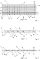
- Fig. 1 is a first layer 5 of a prefabricated component 1 according to the invention (cf. Fig. 4 ) for the production of a blanket 2 (cf. FIG. 7 or FIG. 8 ) shown in supervision.
- the first layer 5 comprises a multiplicity of beam-like or board-shaped wooden elements, each of which extends along a longitudinal direction 4 and, viewed in a second direction 24 that is normal to the longitudinal direction 4, is arranged directly behind one another and connected to one another.
- the wooden elements include wooden elements 3a of a first type and wooden elements 3b of a second type, the wooden elements 3a of the first type and the wooden elements 3b of the second type being arranged alternately one behind the other when viewed in the second direction 24.
- the wood elements 3 a, 3 b are arranged between an upper push wood 19 and a lower push wood 20 or, seen in the second direction 24, the lower push wood 20 forms the beginning of the first layer 5 and the upper push wood 19 the end of the first layer 5.
- the thrust sticks 19, 20 are arranged offset in relation to one another in a third direction 25, the longitudinal direction 4, the second direction 24 and the third direction 25 being mutual stand on each other normally.
- the lower buttwood 20 is flush with an underside 28 of the wooden elements 3a, 3b opposite the upper side 7, cf. Fig. 4 .
- the wooden elements 3a, 3b are joined together by nails 18 (cf. 2 or 3 ) connected (and / or possibly by screws and / or by gluing / gluing), the nails 18 being oriented essentially parallel to the second direction 24.
- the butts 19 and 20 are connected to the wooden elements 3a, 3b by means of partially threaded screws 21 (cf. Fig. 4 ) connected, the partial thread screws 21 being oriented essentially parallel to the second direction 24.
- An upper side 6 of the first layer 5 is formed by upper sides 7 of the wooden elements 3a, 3b.
- a second layer 8 of concrete 9 is again arranged on the top 6, cf. e.g. 2 or 3 .
- Recesses are provided on the upper sides 7 of the wooden elements 3a, 3b, which are filled with the concrete 9 of the second layers 8 in order to ensure a shear-resistant connection between the layers 5, 8.
- recesses 10 of a first type and recesses 11 of a second type are provided on the top sides 7 of the wooden elements 3a of the first type.
- only recesses 10 of the first type are provided on the upper sides of the wooden elements 3b of the second type.
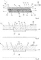
- Fig. 5 shows in detail a recess 10 of the first type in a sectional view
- Fig. 6 shows in detail a recess 11 of the second type in a sectional view.
- both the recess 10 of the first type and the recess 11 of the second type have a trapezoidal cross section in a sectional plane that is spanned by the longitudinal direction 4 and the third direction 25.
- the parallel base sides of the respective trapeze are each extended by the top 7 of the each wooden element 3a, 3b and a bottom 12 of the recesses 10, 11 parallel to the upper side 7.
- the bottom 12 is at a distance from the top 7, which can be referred to as the depth 13 of the recesses 10, 11 and is 20 mm in the exemplary embodiment shown.
- the legs of the respective trapezoid are each formed by a first boundary surface 14 and a second boundary surface 15, i.e. the boundary surfaces 14 and 15 delimit the recesses 10, 11 in the longitudinal direction 4 and connect the base 12 to the upper side 7.
- the boundary surfaces 14, 15 are flat, which enables particularly simple manufacture.
- the floor 12 extends with a floor length 27, which in the exemplary embodiment shown is 250 mm.
- Two consecutive recesses in the longitudinal direction 4 typically have a spacing of 400 mm on the respective wooden element 3a, 3b.
- the recesses 10, 11 completely penetrate the respective wooden element 3a, 3b, i.e. over an entire width 26 of the respective wooden element 3a, 3b, the width 26 being 60 mm in the exemplary embodiment shown.
- the recesses 10 of the first type and the recesses 11 of the second type influence the mechanical properties of the component 1 according to the invention in different ways.
- the reason for this are different orientations of the boundary surfaces 14, 15, more precisely different angles 23 which enclose the boundary surfaces 14, 15 with the longitudinal direction 4.
- the first boundary surface 14 and the second boundary surface 15 with the longitudinal direction 4 include angles 23 of equal size, which are greater than 90 °, so that the recess 10 widens along the third direction 25, cf. . Fig. 5 .
- the angle 23 is 100 ° in each case. This results in an optimal and uniform transmission of pressure loads through the concrete 9 or through the second layer 8 to the first layer 5. An optimal pressure load distribution in component 1 is the result.
- the first boundary surface 14 and the second boundary surface 15 include angles 23 of equal size with the longitudinal direction 4, which are smaller than 90 °, so that the recess 11 tapers along the third direction 25, cf. . Fig. 6 .
- the angle 23 is 75 ° in each case.
- the boundary surfaces 14, 15 form, as it were, undercuts which receive the concrete 9 of the second layer 8. This results in a particularly large and uniform form fit, which enables the particularly uniform transmission of higher tensile forces between the two layers 5, 8.
- a particularly uniform distribution of the tensile load in the component 1 according to the invention is hereby achieved, and the second layer 8 is also prevented from being lifted off from the first layer 5.
- the lifting of the second layer 8 from the first layer 5 is additionally prevented in the exemplary embodiment shown by screws 17 which are turned into the top 6 of the first layer 5 and thus each protrude from the top 6 with a section.
- This section is arranged completely in the second layer 8 and brings about a further positive connection of the two layers 5, 8.
- known structural steel mats are arranged as reinforcement 16 in the concrete 9.
- the respective wooden element 3a of the first type has a sequence of recesses as seen in the longitudinal direction 4, the following partial sequence comprises: recess 10 of the first type, recess 11 of the second type, recess 11 of the second type and recess 10 of the first type, cf. Fig. 2 .
- the alternating arrangement of the wooden elements 3a of the first type and the wooden elements 3b of the second type already described above guarantees an optimal distribution of the pressure and tensile loads typically occurring, in particular in the case of ceilings 2, along the second direction 24.
- the ceiling 2 can now be manufactured extremely quickly and easily on the construction site by means of the prefabricated components 1, for which a desired high quality can be guaranteed on the basis of the prefabrication under defined conditions.
- the required span is ensured by a corresponding length of the wooden elements 3a, 3b measured along the longitudinal direction 4.
- several components 1 can be arranged one behind the other and connected to one another as seen in the second direction 24.
- two directly successive components 1 with different butt members 19, 20 meet each other, whereby a positive connection between these two components 1 is produced.
- the two abutting components 1 are screwed in the area of the butt members 19, 20.
- the partial thread screws 21 are screwed through the lower butt plate 20 of the second component 1 into the upper butt plate 19 of the first component 1. These partial thread screws 21 are therefore visible from the side of the undersides 28, which is why there is an impact formation in non-visible quality.
- the second layers 8 of the two components 1 are surmounted by the butt pieces 19, 20 parallel to the second direction 24.
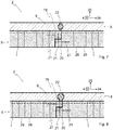
- end faces 29, with which the second layers 8 terminate parallel to the second direction 24, have cutouts 30, cf. Fig. 4 . This creates a receiving volume between the mutually opposite end faces 29 of the two components 1, which is closed by means of potting compound 22 in order to complete the ceiling 2.
- Said receiving volume can also be used to screw in the partial thread screws 21, which are provided for screwing the abutting components 1, from the top 7 of the wooden elements 3a, 3b or from the top 6 of the first layer 5.
- This variant is in Fig. 8 illustrated. That is, the partial thread screws 21 are filled with potting compound 22 before the receiving volume is filled, screwed through the receiving volume from above through the upper pushwood 19 of the first component 1 into the lower pushwood 20 of the second component 1. The receiving volume is then filled with casting compound 22.
- the partial thread screws 21 are no longer visible from any side, in particular not from the side of the undersides 28, so that there is an impact formation in visual quality.
Landscapes
- Engineering & Computer Science (AREA)
- Architecture (AREA)
- Physics & Mathematics (AREA)
- Electromagnetism (AREA)
- Civil Engineering (AREA)
- Structural Engineering (AREA)
Description
Die vorliegende Erfindung betrifft ein Bauteil zur Herstellung einer Decke, das Bauteil umfassend eine Vielzahl von balkenförmigen Holzelementen, die parallel zu einander und quer zu einer Längsrichtung der Holzelemente gesehen unmittelbar hintereinander angeordnet und miteinander verbunden sind und eine erste Lage ausbilden, wobei eine Oberseite der ersten Lage durch Oberseiten der Holzelemente ausgebildet ist, wobei weiters auf der Oberseite der ersten Lage eine zweite Lage aus Beton angeordnet ist, wobei auf den Oberseiten der Holzelemente Ausnehmungen vorgesehen sind, die vom Beton der zweiten Lage ausgefüllt sind, wobei die Ausnehmungen jeweils einen Boden aufweisen, der mit einer Tiefe von der Oberseite des jeweiligen Holzelements beabstandet ist, dass die Ausnehmungen in Längsrichtung gesehen jeweils von einer ersten Begrenzungsfläche und einer dahinter angeordneten zweiten Begrenzungsfläche begrenzt werden.The present invention relates to a component for producing a ceiling, the component comprising a multiplicity of beam-shaped wooden elements which, viewed parallel to one another and transversely to a longitudinal direction of the wooden elements, are arranged one behind the other and connected to one another and form a first layer, an upper side of the first Layer is formed by tops of the wooden elements, wherein a second layer of concrete is further arranged on the top of the first layer, recesses being provided on the tops of the wooden elements, which are filled by the concrete of the second layer, the recesses each having a bottom , which is spaced at a depth from the top of the respective wooden element, such that the recesses, viewed in the longitudinal direction, are each bounded by a first boundary surface and a second boundary surface arranged behind them.
Bei der Ausführung von Holzbauten und darin befindlichen Holzdecken gibt es speziell bei großen Spannweiten häufig Probleme mit dem Schallschutz, mit Schwingungen der Holzdecke sowie mit dem Brandschutz. Insbesondere können von verschiedenen Normen oder Gesetzen vorgeschriebene Werte bzw. Mindestanforderungen in den genannten Bereichen durch reine Holzkonstruktionen gar nicht oder nur schwer und mit sehr hohem Materialaufwand erreicht werden.When executing wooden structures and the wooden ceilings in them, there are often problems with sound insulation, with vibrations of the wooden ceiling and with fire protection, especially with large spans. In particular, values or values prescribed by various standards or laws Minimum requirements in the named areas cannot be achieved at all, or only with difficulty, and with a very high cost of materials, using pure wooden constructions.
Darüberhinaus sind aus dem Stand der Technik Lösungen zur Erreichung besagter Mindestanforderungen in den Bereichen Schallschutz, Schwingungen und Brandschutz bekannt, die als reine Baustellenlösungen bezeichnet werden müssen. Bei diesen Baustellenlösungen wird vor Ort auf der Baustelle auf die jeweils vorhandene Holzkonstruktion im Deckenbereich ein Aufbeton aufgebracht, um den notwendigen Schall- und Brandschutz, sowie die notwendige Steifigkeit für die Schwingungsanforderung zu erreichen. Diese Art der Herstellung ist jedoch sehr aufwendig und erfordert zudem Unterstellungen beim Aufbringen des Aufbetons.In addition, solutions are known from the prior art for achieving said minimum requirements in the areas of sound insulation, vibrations and fire protection, which must be described as pure construction site solutions. With these construction site solutions, a concrete is applied on site to the existing wooden construction in the ceiling area in order to achieve the necessary noise and fire protection, as well as the necessary rigidity for the vibration requirement. However, this type of production is very complex and also requires assumptions when applying the concrete.
Das Aufbringen des nassen Aufbetons auf das trockene Holz hat neben bautechnischer Probleme und einer gewissen unvermeidlichen Verschmutzung - insbesondere auch von anderen Bauteilen bzw. Bauelementen - zur Folge, dass die derart hergestellte Decke nicht sofort belastbar ist, da der Aufbeton erst trocknen muss. Eine nachteilige Zeitverzögerung auf der Baustelle ist die Folge.Applying the wet concrete to the dry wood has structural problems and a certain inevitable contamination - especially from other components or building elements - that the ceiling made in this way is not immediately resilient, since the concrete must first dry. The consequence is an adverse time delay on the construction site.
Insbesondere während der Trocknungsphase des Aufbetons können die solcherart auf den Baustellen hergestellten Decken zudem unterschiedlichen Witterungseinflüssen ausgesetzt sein. Unterschiedliche Qualitäten können die Folge sein, was ebenfalls als nachteilig zu werten ist.In particular, during the drying phase of the concrete, the ceilings produced in this way on construction sites can also be exposed to different weather conditions. Different qualities can be the result, which is also to be regarded as disadvantageous.
Aus der
Ziel der vorliegenden Erfindung ist es, ein Mittel zur Herstellung von holzbasierten Decken zur Verfügung zu stellen, das einerseits die oben genannten Nachteile vermeidet und andererseits das Erreichen von Mindestanforderungen in den Bereichen Schallschutz, Steifigkeit sowie Brandschutz erlaubt. Insbesondere sollen dabei eine gleichbleibend hohe Qualität und eine reduzierte Herstellungszeit auf der Baustelle erzielt werden.The aim of the present invention is to provide a means for producing wood-based ceilings which, on the one hand, avoids the disadvantages mentioned above and, on the other hand, allows minimum requirements in the areas of sound insulation, rigidity and fire protection to be achieved. In particular, a consistently high quality and a reduced manufacturing time on the construction site should be achieved.
Zur Lösung der genannten Aufgabe ist erfindungsgemäß ein Bauteil gemäß Anspruch 1 vorgesehen.To achieve the stated object, a component according to
Bei einem Bauteil zur Herstellung einer Decke, das Bauteil umfassend eine Vielzahl von balkenförmigen Holzelementen, die parallel zu einander und quer zu einer Längsrichtung der Holzelemente gesehen unmittelbar hintereinander angeordnet und miteinander verbunden sind und eine erste Lage ausbilden, wobei eine Oberseite der ersten Lage durch Oberseiten der Holzelemente ausgebildet ist, wobei weiters auf der Oberseite der ersten Lage eine zweite Lage aus Beton angeordnet ist, ist vorgesehen, dass auf den Oberseiten der Holzelemente Ausnehmungen vorgesehen sind, die vom Beton der zweiten Lage ausgefüllt sind.In the case of a component for producing a ceiling, the component comprises a multiplicity of beam-shaped wooden elements which, viewed parallel to one another and transversely to a longitudinal direction of the wooden elements, are arranged one behind the other and connected to one another and form a first layer, an upper side of the first layer being formed by upper sides of the wooden elements, wherein a second layer of concrete is also arranged on the upper side of the first layer, it is provided that recesses are provided on the upper sides of the wooden elements which are filled with the concrete of the second layer.
Ein solches Bauteil kann generell als lasttragendes Bauelement verwendet werden.Such a component can generally be used as a load-bearing component.
Die Holzelemente bestehen vorzugsweise jeweils aus Konstruktionsvollholz, wobei die erste Lage eine Art Brettstapelelement ausbildet. D.h. die Holzelemente sind quer zur Längsrichtung so hintereinander angeordnet, dass sie einander berühren.The wooden elements are preferably made of solid construction wood, the first layer of a kind Forms board stack element. Ie the wooden elements are arranged one behind the other transversely to the longitudinal direction so that they touch each other.
Die Verbindung der Holzelemente erfolgt kraftschlüssig und im Wesentlichen punktförmig, vorzugweise durch Vernagelung, z.B. mittels eines Druckluftnaglers. Typischerweise sind die Nägel im Abstand von 40 cm bis 60 cm, beispielsweise 50 cm, zueinander angeordnet. Die Nägel können dabei zueinander höhenversetzt entlang der Holzelemente bzw. in Längsrichtung gesehen angeordnet sein. Vorzugsweise werden jeweils zwei hintereinander angeordnete Holzelemente von einem Nagel voll durchdrungen, wobei der Nagel in ein dahinter angeordnetes drittes Holzelement ebenfalls noch ein Stück weit (z.B. 2 cm bis 3 cm) eindringt, ohne dieses vollständig zu durchdringen.The connection of the wooden elements is non-positive and essentially point-shaped, preferably by nailing, for example using a pneumatic nailer. The nails are typically arranged at a distance of 40 cm to 60 cm, for example 50 cm, from one another. The nails can be arranged offset in height from one another along the wooden elements or viewed in the longitudinal direction. Preferably, two wooden elements arranged one behind the other are fully penetrated by a nail, the nail also penetrating a little further into a third wooden element arranged behind it (for example 2 cm to 3 cm) without completely penetrating it.
Alternativ oder zusätzlich können auch andere Verbindungsmittel vorgesehen sein, beispielsweise Dübel, Schrauben oder eine Verklebung bzw. Verleimung.As an alternative or in addition, other connection means can also be provided, for example dowels, screws or an adhesive or gluing.
In der zweiten Lage kann eine Bewehrung vorgesehen sein, wie sie in Betonschichten üblich ist, also insbesondere aus Baustahl bzw. Baustahlmatten.In the second layer, reinforcement can be provided as is customary in concrete layers, that is to say in particular made of structural steel or reinforcing steel mesh.
Durch die mit dem Beton der zweiten Lage gefüllten Ausnehmungen wird eine formschlüssige, schubfeste Verbindung zwischen der ersten Lage und der zweiten Lage gewährleistet. Es handelt sich dabei um eine rein mechanische Verbindung, für die kein chemischer Kleber benötigt wird und die somit sehr umweltfreundlich ist.The recesses filled with the concrete of the second layer ensure a positive, shear-resistant connection between the first layer and the second layer. It is a purely mechanical connection, for which no chemical adhesive is required and which is therefore very environmentally friendly.
Die Ausnehmungen werden in die Holzelemente eingefräst. Die Ausnehmungen können auch als Kerven ausgeführt sein. Manchmal werden die Ausnehmungen auch als Kerven bezeichnet, obgleich ein Boden der jeweiligen Ausnehmung nicht spitz zulaufend, sondern im Wesentlichen eben ausgeführt ist.The recesses are milled into the wooden elements. The recesses can also be designed as Kerven. Sometimes the recesses are also called kerven, although a bottom of the respective recess is not tapered, but is essentially flat.
Durch das erfindungsgemäße Bauteil wird ein Hybridbauteil geschaffen, das außerhalb der Baustelle in einer externen Produktionsstätte unter kontrollierten Bedingungen produziert und vorgefertigt auf die Baustelle geliefert werden kann. Insbesondere kann das Bauteil unter konstanten klimatischen Bedingungen hergestellt werden, ohne dass das Bauteil Witterungseinflüssen ausgesetzt ist. Die gewünschte sehr hohe Qualität der Bauteile kann somit garantiert werden. Das Aufbringen des Betons bzw. Aufbetons auf der Baustelle entfällt, sodass eine trockene Bauweise erfolgen kann. Zur Baustelle kann ein sofort voll belastbares und trockenes Bauteil geliefert werden, sodass insbesondere keine Unterstellungen einer mittels der erfindungsgemäßen Bauteile hergestellten Decke notwendig sind. Durch den hohen Vorfertigungsgrad wird eine Verkürzung der Bauzeiten durch schnelle Montagezeiten vor Ort erreicht.The component according to the invention creates a hybrid component which can be produced outside the construction site in an external production facility under controlled conditions and can be delivered prefabricated to the construction site. In particular, the component can be manufactured under constant climatic conditions without the component being exposed to weather influences. The desired very high quality of the components can thus be guaranteed. There is no need to apply the concrete or concrete on the construction site, so that a dry construction method can be used. An immediately fully loadable and dry component can be delivered to the construction site, so that in particular no subjugation of a ceiling produced by means of the components according to the invention is necessary. Due to the high degree of prefabrication, the construction times are shortened by quick assembly times on site.
Die Holzelemente dienen primär zur Aufnahme von Zugkräften, wohingegen der Beton bzw. Aufbeton primär zur Aufnahme von Druckkräften dient. Durch die schubfeste Verbindung der beiden Lagen wird eine extrem starre Verbindung gewährleistet, was ein sehr biegesteifes Bauelement zur Folge hat, das den oben genannten Anforderungen gerecht wird. Durch die Verbindung von Holz und Beton des (Hybrid-)Bauteils werden sowohl die notwendigen statischen als auch schalltechnischen, schwingungstechnischen und brandschutztechnischen Voraussetzungen geschaffen, um auch große Spannweiten als Holzbauteil herstellen zu können.The wooden elements primarily serve to absorb tensile forces, whereas the concrete or concrete serves primarily to absorb compressive forces. The shear-resistant connection of the two layers ensures an extremely rigid connection, which results in a very rigid component that meets the above requirements. The combination of wood and concrete of the (hybrid) component creates the necessary static as well as sound, vibration and fire protection requirements in order to be able to manufacture large spans as a wooden component.
Die Form der Ausnehmungen kann unterschiedlich ausgestaltet sein. Um eine besonders einfache Herstellungsweise erzielen und gleichzeitig gewünschte mechanische Eigenschaften einstellen zu können, ist es bei einer bevorzugten Ausführungsform des erfindungsgemäßen Bauteils vorgesehen, dass die Ausnehmungen jeweils in einer Schnittebene einen trapezförmigen Querschnitt aufweisen, wobei die Schnittebene normal auf die Oberseite des jeweiligen Holzelements steht und parallel zur Längsrichtung ist. Mit anderen Worten liegt der Vektor der Längsrichtung jeweils in bzw. parallel zu der Schnittebene.The shape of the recesses can be designed differently. In order to achieve a particularly simple production method and at the same time to be able to set the desired mechanical properties, it is provided in a preferred embodiment of the component according to the invention that the recesses each have a trapezoidal cross section in a sectional plane, the sectional plane standing normally on the top of the respective wooden element and is parallel to the longitudinal direction. In other words, the vector of the longitudinal direction lies in or parallel to the cutting plane.
Die Trapezform einer Ausnehmung kann insbesondere derart eingestellt werden, dass parallele Grundseiten des Trapez' durch die verlängert gedachte Oberseite des jeweiligen Holzelements sowie einen zur Oberseite parallelen Boden der Ausnehmung ausgebildet werden. Die mechanischen Eigenschaften lassen sich sodann insbesondere durch die Ausrichtung der die Ausnehmung begrenzenden Schenkel des Trapez' gezielt beeinflussen.The trapezoidal shape of a recess can in particular be set such that parallel base sides of the trapezoid are formed by the elongated top of the respective wooden element and a bottom of the recess parallel to the top. The mechanical properties can then be specifically influenced by the alignment of the legs of the trapezoid delimiting the recess.
Beim erfindungsgemäßen Bauteil ist vorgesehen, dass die Ausnehmungen jeweils einen Boden aufweisen, der mit einer Tiefe von der Oberseite des jeweiligen Holzelements beabstandet ist, dass die Ausnehmungen in Längsrichtung gesehen jeweils von einer ersten Begrenzungsfläche und einer dahinter angeordneten zweiten Begrenzungsfläche begrenzt werden und dass die Ausnehmungen Ausnehmungen eines ersten Typs umfassen, wobei bei den Ausnehmungen des ersten Typs jeweils die erste Begrenzungsfläche und/oder die zweite Begrenzungsfläche mit der Längsrichtung einen Winkel einschließt, der größer als 90°, bevorzugt im Bereich von 95° bis 120°, besonders bevorzugt im Bereich von 95° bis 105°, ist.In the component according to the invention it is provided that the recesses each have a bottom which is at a depth from the top of the is spaced from the respective wooden element, that the recesses, viewed in the longitudinal direction, are each delimited by a first boundary surface and a second boundary surface arranged behind them, and that the recesses comprise recesses of a first type, the first boundary surface and / or the second one in each case in the recesses of the first type Boundary surface with the longitudinal direction includes an angle that is greater than 90 °, preferably in the range from 95 ° to 120 °, particularly preferably in the range from 95 ° to 105 °.
Die Tiefe wird vorzugsweise parallel zu einer dritten Richtung gemessen, die normal zur Längsrichtung und auf die Oberseite des Holzelements steht.The depth is preferably measured parallel to a third direction, which is normal to the longitudinal direction and on the top of the wooden element.
Vorzugsweise schließen die erste Begrenzungsfläche und die zweite Begrenzungsfläche an den Boden an.The first boundary surface and the second boundary surface preferably adjoin the floor.
Die derart ausgebildeten Ausnehmungen des ersten Typs können somit insbesondere den oben beschriebenen trapezförmigen Querschnitt haben, wobei die erste Begrenzungsfläche und die zweite Begrenzungsfläche die Schenkel des Trapez' ausbilden.The recesses of the first type formed in this way can thus in particular have the trapezoidal cross section described above, the first boundary surface and the second boundary surface forming the legs of the trapezoid.
Vorzugsweise verläuft der Boden parallel zur Längsrichtung, sodass die erste Begrenzungsfläche und die zweite Begrenzungsfläche denselben Winkel mit dem Boden einschließen wie mit der Längsrichtung.The floor preferably runs parallel to the longitudinal direction, so that the first boundary surface and the second boundary surface enclose the same angle with the floor as with the longitudinal direction.
In jedem Fall ergibt sich eine sich nach oben bzw. zur Oberseite des jeweiligen Holzelements zumindest einseitig weitende Ausnehmung, was eine gute Drucklastverteilung im Bauteil bewirkt, wobei der entsprechende Druck über die zweite Lage auf die erste Lage parallel zur dritten Richtung eingebracht wird.In any case, there is a recess that widens upwards or to the top of the respective wooden element at least on one side, which results in a good pressure load distribution in the component, the corresponding pressure being introduced via the second layer onto the first layer parallel to the third direction.
Um die Drucklastverteilung weiter zu optimieren und insbesondere besonders gleichmäßig gestalten zu können, ist es bei einer besonders bevorzugten Ausführungsform des erfindungsgemäßen Bauteils vorgesehen, dass bei den Ausnehmungen des ersten Typs jeweils die erste Begrenzungsfläche und die zweite Begrenzungsfläche mit der Längsrichtung einen, vorzugsweise gleich großen, Winkel einschließen, der größer als 90°, bevorzugt im Bereich von 95° bis 120°, besonders bevorzugt im Bereich von 95° bis 105°, ist. In diesem Fall ergibt sich eine sich nach oben bzw. zur Oberseite des jeweiligen Holzelements beidseitig weitende Ausnehmung, was eine besonders gute Drucklastverteilung im Bauteil bewirkt. Insbesondere können die erste und zweite Begrenzungsfläche mit der Längsrichtung den gleichen Winkel einschließen, sodass eine besonders gleichmäßige Einbringung des Drucks von der zweiten Lage in die erste Lage und damit eine besonders gleichmäßige Drucklastverteilung im Bauteil erzielt wird.In order to further optimize the pressure load distribution and in particular to be able to make it particularly even, it is In a particularly preferred embodiment of the component according to the invention, it is provided that, in the recesses of the first type, the first boundary surface and the second boundary surface enclose an angle, preferably of the same size, with the longitudinal direction, which is greater than 90 °, preferably in the range from 95 ° to 120 °, particularly preferably in the range from 95 ° to 105 °. In this case there is a recess widening upwards or to the top of the respective wooden element on both sides, which results in a particularly good pressure load distribution in the component. In particular, the first and second boundary surfaces can enclose the same angle with the longitudinal direction, so that a particularly uniform introduction of the pressure from the second layer into the first layer and thus a particularly uniform pressure load distribution in the component is achieved.
Beim erfindungsgemäßen Bauteil ist vorgesehen, dass die Ausnehmungen Ausnehmungen eines zweiten Typs umfassen, wobei bei den Ausnehmungen des zweiten Typs jeweils die erste Begrenzungsfläche und/oder die zweite Begrenzungsfläche mit der Längsrichtung einen Winkel einschließt, der kleiner als 90°, bevorzugt im Bereich von 60° bis 85°, besonders bevorzugt im Bereich von 70° bis 80°, ist.In the component according to the invention, it is provided that the recesses comprise recesses of a second type, with the recesses of the second type in each case including the first boundary surface and / or the second boundary surface with the longitudinal direction an angle which is less than 90 °, preferably in the range of 60 ° to 85 °, particularly preferably in the range from 70 ° to 80 °.
Vorzugsweise schließen die erste Begrenzungsfläche und die zweite Begrenzungsfläche an den Boden an.The first boundary surface and the second boundary surface preferably adjoin the floor.
Die derart ausgebildeten Ausnehmungen des zweiten Typs können somit insbesondere den oben beschriebenen trapezförmigen Querschnitt haben, wobei die erste Begrenzungsfläche und die zweite Begrenzungsfläche die Schenkel des Trapez' ausbilden.The recesses of the second type formed in this way can thus have, in particular, the trapezoidal cross-section described above, the first boundary surface and the second boundary surface forming the legs of the trapezoid.
Vorzugsweise verläuft der Boden parallel zur Längsrichtung, sodass die erste Begrenzungsfläche und die zweite Begrenzungsfläche denselben Winkel mit dem Boden einschließen wie mit der Längsrichtung.The base preferably runs parallel to the longitudinal direction, so that the first boundary surface and the second Boundary surface form the same angle with the ground as with the longitudinal direction.
In jedem Fall ergibt sich eine sich nach oben bzw. zur Oberseite des jeweiligen Holzelements zumindest einseitig verjüngende Ausnehmung, sodass gewissermaßen eine Hinterschneidung ausgebildet wird, welche den Beton der zweiten Lage aufnimmt. Dies resultiert in einem Formschluss, der die Übertragung von Zugkräften zwischen den beiden Lagen, d.h. mit einem Richtungsanteil parallel zur dritten Richtung, erlaubt. Entsprechend ist eine vorteilhafte Zuglastverteilung im erfindungsgemäßen Bauelement gewährleistet. Damit einhergehend wird ein Abheben der zweiten Lage von der ersten Lage unterbunden.In any case, there is a recess that tapers at least on one side upwards or to the top side of the respective wooden element, so that, as it were, an undercut is formed which receives the concrete of the second layer. This results in a form fit that prevents the transfer of tensile forces between the two layers, i.e. with a directional component parallel to the third direction. Accordingly, an advantageous tensile load distribution is ensured in the component according to the invention. As a result, the second layer is prevented from being lifted from the first layer.
Die Ausnehmungen des zweiten Typs sind zusätzlich zu den Ausnehmungen des ersten Typs vorhanden, sodass die oben geschilderte vorteilhafte Drucklastverteilung weiterhin gegeben ist.The recesses of the second type are present in addition to the recesses of the first type, so that the advantageous pressure load distribution described above continues to exist.
Um die Zuglastverteilung weiter zu optimieren und insbesondere besonders gleichmäßig gestalten zu können, ist es bei einer besonders bevorzugten Ausführungsform des erfindungsgemäßen Bauteils vorgesehen, dass bei den Ausnehmungen des zweiten Typs jeweils die erste Begrenzungsfläche und die zweite Begrenzungsfläche mit der Längsrichtung einen, vorzugsweise gleich großen, Winkel einschließen, der kleiner als 90°, bevorzugt im Bereich von 60° bis 85°, besonders bevorzugt im Bereich von 70° bis 80°, ist. In diesem Fall ergibt sich eine sich nach oben bzw. zur Oberseite des jeweiligen Holzelements beidseitig verjüngende Ausnehmung, sodass gewissermaßen beide Begrenzungsflächen Hinterschneidungen ausbilden, welche den Beton der zweiten Lage aufnehmen. Dies resultiert in einem besonders großen Formschluss, was die Übertragung höherer Zugkräfte zwischen den beiden Lagen ermöglicht. Insbesondere können die erste und zweite Begrenzungsfläche mit der Längsrichtung den gleichen Winkel einschließen, sodass eine besonders gleichmäßige Übertragung des Zugs zwischen der ersten und zweiten Lage und damit eine besonders gleichmäßige Zuglastverteilung im Bauteil erzielt wird.In order to further optimize the tensile load distribution and, in particular, to be able to design it particularly uniformly, it is provided in a particularly preferred embodiment of the component according to the invention that, in the recesses of the second type, the first boundary surface and the second boundary surface with the longitudinal direction each have a preferably the same size, Include an angle that is less than 90 °, preferably in the range from 60 ° to 85 °, particularly preferably in the range from 70 ° to 80 °. In this case, there is a recess tapering upwards or to the top of the respective wooden element on both sides, so that to a certain extent both boundary surfaces form undercuts which receive the concrete of the second layer. This results in a particularly large form fit, which enables the transfer of higher tensile forces between the two layers. In particular, the first and second boundary surfaces can be connected to the Include the same angle in the longitudinal direction, so that a particularly uniform transmission of the tension between the first and second layer and thus a particularly uniform tension load distribution in the component is achieved.
Wie bereits erwähnt, ist es bei einer besonders bevorzugten Ausführungsform des erfindungsgemäßen Bauteils vorgesehen, dass der Boden parallel zur Längsrichtung verläuft. Dies gewährleistet u.a. eine besonders einfache Herstellung der Ausnehmungen.As already mentioned, it is provided in a particularly preferred embodiment of the component according to the invention that the floor runs parallel to the longitudinal direction. Among other things, this ensures a particularly simple production of the recesses.
Bei einer besonders bevorzugten Ausführungsform des erfindungsgemäßen Bauteils ist vorgesehen, dass die Tiefe im Bereich von 10 mm bis 30 mm liegt, bevorzugt im Bereich von 15 mm bis 25 mm. Beispielsweise kann die Tiefe 20 mm betragen. Diese relativ geringen Tiefen genügen, um eine schubfeste Verbindung zwischen der ersten Lage und der zweiten Lage zuverlässig zu gewährleisten. Darüberhinaus wird auch die geschilderte Ausgestaltung der Ausnehmungen des ersten Typs sowie des zweiten Typs ermöglicht. Gleichzeitig wird die mechanische Stabilität der Holzelemente an sich nicht wesentlich beeinträchtigt, da der Materialabtrag gering gehalten wird.In a particularly preferred embodiment of the component according to the invention it is provided that the depth is in the range from 10 mm to 30 mm, preferably in the range from 15 mm to 25 mm. For example, the depth can be 20 mm. These relatively shallow depths are sufficient to reliably ensure a shear-resistant connection between the first layer and the second layer. In addition, the described design of the recesses of the first type and of the second type is also made possible. At the same time, the mechanical stability of the wooden elements per se is not significantly impaired since the material removal is kept low.
Bei einer besonders bevorzugten Ausführungsform des erfindungsgemäßen Bauteils ist vorgesehen, dass der Boden eine parallel zur Längsrichtung gemessene Bodenlänge aufweist, die im Bereich von 100 mm bis 400 mm liegt, bevorzugt im Bereich von 120 mm bis 320 mm. Beispielsweise kann die Bodenlänge 250 mm betragen. Somit können auf einem Holzelement, das typischerweise mehrere Meter lang ist, entlang der Längsrichtung problemlos mehrere Ausnehmungen hintereinander angeordnet werden. Deren Abstand in Längsrichtung zueinander kann dabei typischerweise im Bereich von 200 mm bis 1000 mm liegen, z.B. bei 400 mm.In a particularly preferred embodiment of the component according to the invention it is provided that the floor has a floor length measured parallel to the longitudinal direction, which is in the range from 100 mm to 400 mm, preferably in the range from 120 mm to 320 mm. For example, the floor length can be 250 mm. Thus, on a wooden element, which is typically several meters long, several recesses can easily be arranged one behind the other along the longitudinal direction. Their distance in the longitudinal direction from one another can typically be in the range from 200 mm to 1000 mm, for example 400 mm.
Aufgrund der geschilderten, relativ kompakten Abmessungen können die Ausnehmungen auch als im Wesentlichen punktförmige Verbindungen zwischen der ersten Lage und der zweiten Lage angesehen werden.Due to the described, relatively compact dimensions, the recesses can also be regarded as essentially point-like connections between the first layer and the second layer.
Beim erfindungsgemäßen Bauteil ist vorgesehen, dass die Holzelemente Holzelemente eines zweiten Typs umfassen, wobei die Holzelemente des zweiten Typs ausschließlich Ausnehmungen des ersten Typs aufweisen. Entsprechend tragen die Holzelemente des zweiten Typs wesentlich zur optimalen Drucklastverteilung bei.In the component according to the invention, it is provided that the wooden elements comprise wooden elements of a second type, the wooden elements of the second type exclusively having recesses of the first type. Accordingly, the wooden elements of the second type contribute significantly to the optimal pressure load distribution.
Theoretisch wäre es denkbar, ausschließlich Holzelemente des zweiten Typs zu verwenden, da Drucklasten den vornehmlichen Lastfall darstellen.Theoretically, it would be conceivable to use only wooden elements of the second type, since pressure loads represent the primary load case.
Um jedenfalls ein Abheben der zweiten Lage von der ersten Lage zu unterbinden, ist es bei einer bevorzugten Ausführungsform des erfindungsgemäßen Bauteils vorgesehen, dass Schrauben in die erste Lage eingeschraubt sind und jeweils mit einem Abschnitt von der Oberseite der ersten Lage abstehen, wobei der Abschnitt vollständig innerhalb der zweiten Lage angeordnet ist. Vorzugsweise sind die Schrauben dabei von der Oberseite der ersten Lage her in die erste Lage eingeschraubt.In order to prevent lifting of the second layer from the first layer, it is provided in a preferred embodiment of the component according to the invention that screws are screwed into the first layer and each protrude with a section from the top of the first layer, the section being complete is arranged within the second layer. The screws are preferably screwed into the first layer from the top of the first layer.
D.h. die Schrauben gewährleisten bereits eine gewisse, vorzugsweise zusätzliche, zugfeste Verbindung zwischen der ersten Lage und der zweiten Lage, die extrem leicht herstellbar ist, indem die Schrauben vor dem Aufbringen des Betons der zweiten Lage in die erste Lage eingeschraubt werden.I.e. the screws already ensure a certain, preferably additional, tensile connection between the first layer and the second layer, which is extremely easy to produce by screwing the screws into the first layer before the concrete of the second layer is applied.
Es sei bemerkt, dass nicht in jedes Holzelement der ersten Lage eine Schraube eingedreht bzw. eingeschraubt sein muss.It should be noted that a screw does not have to be screwed or screwed into every wooden element of the first layer.
Beim erfindungsgemäßen Bauteil ist vorgesehen, dass die Holzelemente Holzelemente eines ersten Typs umfassen, wobei die Holzelemente des ersten Typs sowohl Ausnehmungen des ersten Typs als auch Ausnehmungen des zweiten Typs aufweisen. Durch die Holzelemente des ersten Typs wird entsprechend nicht nur eine gute Drucklastverteilung im Bauteil bewirkt, sondern auch eine gute zugfeste Verbindung zwischen den beiden Lagen bzw. eine gute Zuglastverteilung im Bauteil. Theoretisch wäre es denkbar, ausschließlich Holzelemente des ersten Typs zu verwenden, da hierdurch sowohl Druckbelastungen als auch Zugbelastungen Rechnung getragen werden kann.In the component according to the invention it is provided that the wooden elements comprise wooden elements of a first type, the wooden elements of the first type having both recesses in the have first type and recesses of the second type. The wooden elements of the first type not only result in a good pressure load distribution in the component, but also a good tensile connection between the two layers or a good tension load distribution in the component. In theory, it would be conceivable to use only wooden elements of the first type, since this can take into account both compressive and tensile loads.
Um den entlang der Längsrichtung typischerweise auftretenden Druck- und Zuglasten, insbesondere bei Decken, optimal Rechnung zu tragen, ist es bei einer besonders bevorzugten Ausführungsform des erfindungsgemäßen Bauteils vorgesehen, dass das jeweilige Holzelement des ersten Typs in Längsrichtung gesehen eine Abfolge von Ausnehmungen aufweist, die folgende Teilabfolge umfasst: Ausnehmung des ersten Typs, Ausnehmung des zweiten Typs, Ausnehmung des zweiten Typs und Ausnehmung des ersten Typs.In order to optimally take into account the pressure and tensile loads typically occurring along the longitudinal direction, in particular in the case of ceilings, it is provided in a particularly preferred embodiment of the component according to the invention that the respective wooden element of the first type has a sequence of recesses, seen in the longitudinal direction, which comprises the following partial sequence: recess of the first type, recess of the second type, recess of the second type and recess of the first type.
Vorzugsweise kann folgende Teilabfolge von der Abfolge von Ausnehmungen umfasst sein: Ausnehmung des ersten Typs, Ausnehmung des zweiten Typs, Ausnehmung des zweiten Typs, Ausnehmung des ersten Typs und Ausnehmung des ersten Typs.The following partial sequence can preferably be included in the sequence of recesses: recess of the first type, recess of the second type, recess of the second type, recess of the first type and recess of the first type.
Um den quer zur Längsrichtung typischerweise auftretenden Druck- und Zuglasten, insbesondere bei Decken, optimal Rechnung zu tragen, ist es beim erfindungsgemäßen Bauteil vorgesehen, dass quer zur Längsrichtung gesehen auf mindestens ein Holzelement des zweiten Typs mindestens ein Holzelement des ersten Typs folgt und umgekehrt. Dies umfasst z.B. folgende Abfolge - quer zur Längsrichtung, insbesondere in einer zweiten Richtung, gesehen - von Holzelementen: L Holzelemente des zweiten Typs, M Holzelemente des ersten Typs, N Holzelemente des zweiten Typs. Diese Abfolge könnte z.B. fortgesetzt werden mit o Holzelementen des ersten Typs oder mit o Holzelementen des ersten Typs gefolgt von P Holzelementen des zweiten Typs usw. Dabei stehen L, M, N, O, P für ganze Zahlen größer null.In order to optimally take into account the compressive and tensile loads typically occurring transversely to the longitudinal direction, in particular in the case of ceilings, it is provided in the component according to the invention that, seen transversely to the longitudinal direction, at least one wooden element of the second type is followed by at least one wooden element of the first type and vice versa. This includes, for example, the following sequence - transverse to the longitudinal direction, in particular in one second direction, seen - from wooden elements: L wooden elements of the second type, M wooden elements of the first type, N wooden elements of the second type. This sequence could, for example, be continued with o wooden elements of the first type or with o wooden elements of the first type followed by P wooden elements of the second type etc. L, M, N, O, P stand for integers greater than zero.
Vorzugsweise umfasst die Abfolge der Holzelemente quer zur Längsrichtung gesehen genau ein Holzelement des zweiten Typs gefolgt von genau einem Holzelement des ersten Typs und umgekehrt. D.h. in diesem Fall ist zumindest folgende Abfolge umfasst: ein Holzelement des zweiten Typs, ein Holzelement des ersten Typs, ein Holzelement des zweiten Typs.The sequence of the wooden elements, viewed transversely to the longitudinal direction, comprises exactly one wooden element of the second type followed by exactly one wooden element of the first type and vice versa. I.e. in this case at least the following sequence is included: a wooden element of the second type, a wooden element of the first type, a wooden element of the second type.
Um eine besonders einfache Herstellbarkeit der Ausnehmungen zu ermöglichen, ist es bei einer bevorzugten Ausführungsform des erfindungsgemäßen Bauteils vorgesehen, das sich die Ausnehmungen jeweils über eine gesamte Breite des jeweiligen Holzelements erstrecken, wobei die Breite in einer zweiten Richtung gemessen wird, die normal auf die Längsrichtung steht und parallel zur Oberseite des Holzelements ist. Die Ausnehmungen können auf diese Weise ins Holzelement gefräst werden. Typischerweise liegt die Breite der Holzelemente im Bereich von 40 mm bis 120 mm, insbesondere im Bereich von 50 mm bis 80 mm, beispielsweise bei 60 mm.In order to make the recesses particularly easy to produce, it is provided in a preferred embodiment of the component according to the invention that the recesses each extend over an entire width of the respective wooden element, the width being measured in a second direction that is normal to the longitudinal direction stands and is parallel to the top of the wooden element. In this way, the recesses can be milled into the wooden element. The width of the wooden elements is typically in the range from 40 mm to 120 mm, in particular in the range from 50 mm to 80 mm, for example 60 mm.
Die Längsrichtung, die zweite Richtung und die dritte Richtung stehen wechselseitig normal aufeinander.The longitudinal direction, the second direction and the third direction are mutually normal.
Eine entlang der dritten Richtung gemessene Höhe der Holzelemente liegt typischerweise im Bereich von 12 cm bis 32 cm. Eine entlang der dritten Richtung gemessene Höhe der zweiten Lage liegt typischerweise im Bereich von 8 cm bis 18 cm, womit sich eine in der dritten Richtung gemessene Gesamthöhe des erfindungsgemäßen Bauteils ergibt, die typischerweise im Bereich von 20 cm bis 50 cm liegt.A height of the wooden elements measured along the third direction is typically in the range from 12 cm to 32 cm. A height of the second layer measured along the third direction is typically in the range from 8 cm to 18 cm, which results in a total height of the component according to the invention measured in the third direction, which is typically in the range from 20 cm to 50 cm.
Entsprechend können mit dem erfindungsgemäßen Bauteil - insbesondere bei damit hergestellten Decken - problemlos Stützweiten im Bereich von 4 m bis 12 m realisiert werden, wobei die Stützweiten im Wesentlichen (entlang der Längsrichtung gemessenen) Längen der Holzelemente entsprechen.Correspondingly, span widths in the range from 4 m to 12 m can be realized with the component according to the invention, in particular with ceilings produced therewith, the span widths essentially corresponding (measured in the longitudinal direction) to the lengths of the wooden elements.
Die Erfindung wird nun anhand von Ausführungsbeispielen näher erläutert. Die Zeichnungen sind beispielhaft und sollen den Erfindungsgedanken zwar darlegen, ihn aber keinesfalls einengen oder gar abschließend wiedergeben.The invention will now be explained in more detail on the basis of exemplary embodiments. The drawings are exemplary and are intended to illustrate the idea of the invention, but in no way to narrow it down or even reproduce it conclusively.
Dabei zeigt:
- Fig. 1
- eine Aufsicht auf eine erste Lage eines erfindungsgemäßen Bauteils
- Fig. 2
- einen Schnitt durch das erfindungsgemäße Bauteil gemäß der Schnittlinie II-II in
Fig. 1 (Holzelement, erster Typ) - Fig. 3
- einen Schnitt durch das erfindungsgemäße Bauteil gemäß der Schnittlinie III-III in
Fig. 1 (Holzelement, zweiter Typ) - Fig. 4
- einen Schnitt durch das erfindungsgemäße Bauteil gemäß der Schnittlinie IV-IV in
Fig. 1 , wobei diese Schnittlinie inFig. 2 und Fig. 3 ebenfalls angedeutet ist - Fig. 5
- eine Detailansicht einer Ausnehmung eines ersten Typs in einer Schnittdarstellung analog zu
Fig. 3 - Fig. 6
- eine Detailansicht einer Ausnehmung eines zweiten Typs in einer Schnittdarstellung analog zu
Fig. 2 - Fig. 7
- einen Abschnitt einer Decke aus erfindungsgemäßen Bauteilen in einer Schnittdarstellung analog zu
Fig. 4 , wobei eine Stoßausbildung in Nichtsichtqualität vorgesehen ist - Fig. 8
- einen Abschnitt einer Decke aus erfindungsgemäßen Bauteilen in einer Schnittdarstellung analog zu
Fig. 4 , wobei die Stoßausbildung in Sichtqualität vorgesehen ist
- Fig. 1
- a top view of a first layer of a component according to the invention
- Fig. 2
- a section through the component according to the invention according to section line II-II in
Fig. 1 (Wooden element, first type) - Fig. 3
- a section through the component according to the invention along the section line III-III in
Fig. 1 (Wooden element, second type) - Fig. 4
- a section through the component according to the invention along the section line IV-IV in
Fig. 1 , this line of intersection in2 and 3 is also indicated - Fig. 5
- a detailed view of a recess of a first type in a sectional view analogous to
Fig. 3 - Fig. 6
- a detailed view of a recess of a second type in a sectional view analogous to
Fig. 2 - Fig. 7
- a section of a ceiling of components according to the invention in a sectional view analogous to
Fig. 4 , wherein a shock training in non-visual quality is provided - Fig. 8
- a section of a ceiling of components according to the invention in a sectional view analogous to
Fig. 4 , the shock training is provided in visual quality
In
Die Holzelemente umfassen dabei Holzelemente 3a eines ersten Typs sowie Holzelemente 3b eines zweiten Typs, wobei in der zweiten Richtung 24 gesehen die Holzelemente 3a des ersten Typs und die Holzelemente 3b des zweiten Typs abwechselnd hintereinander angeordnet sind. Die Holzelemente 3a, 3b sind zwischen einem oberen Stoßholz 19 und einem unteren Stoßholz 20 angeordnet bzw. bildet das untere Stoßholz 20 in der zweiten Richtung 24 gesehen den Anfang der ersten Lage 5 und das obere Stoßholz 19 das Ende der ersten Lage 5.The wooden elements include
Die Stoßhölzer 19, 20 sind in einer dritten Richtung 25 versetzt zueinander angeordnet, wobei die Längsrichtung 4, die zweite Richtung 24 und die dritte Richtung 25 wechselseitig normal aufeinander stehen. Dabei schließt das untere Stoßholz 20 bündig mit einer der Oberseite 7 gegenüberliegenden Unterseite 28 der Holzelemente 3a, 3b ab, vgl.
Die Holzelemente 3a, 3b sind miteinander durch Nägel 18 (vgl.
Eine Oberseite 6 der ersten Lage 5 ist durch Oberseiten 7 der Holzelemente 3a, 3b ausgebildet. Auf der Oberseite 6 ist wiederum eine zweite Lage 8 aus Beton 9 angeordnet, vgl. z.B.
Auf den Oberseiten 7 der Holzelemente 3a, 3b sind Ausnehmungen vorgesehen, die vom Beton 9 der zweiten Lagen 8 ausgefüllt sind, um eine schubfeste Verbindung zwischen den Lagen 5, 8 zu gewährleisten. Konkret sind auf den Oberseiten 7 der Holzelemente 3a des ersten Typs Ausnehmungen 10 eines ersten Typs sowie Ausnehmungen 11 eines zweiten Typs vorgesehen. Auf den Oberseiten der Holzelemente 3b des zweiten Typs sind hingegen ausschließlich Ausnehmungen 10 des ersten Typs vorgesehen.Recesses are provided on the
Die Schenkel des jeweiligen Trapez' sind jeweils durch eine erste Begrenzungsfläche 14 und eine zweite Begrenzungsfläche 15 ausgebildet, d.h. die Begrenzungsflächen 14 und 15 begrenzen die Ausnehmungen 10, 11 in Längsrichtung 4 und verbinden den Boden 12 mit der Oberseite 7.The legs of the respective trapezoid are each formed by a
Im dargestellten Ausführungsbeispiel sind die Begrenzungsflächen 14, 15 eben ausgeführt, was eine besonders einfache Herstellung ermöglicht.In the illustrated embodiment, the boundary surfaces 14, 15 are flat, which enables particularly simple manufacture.
In Längsrichtung 4 erstreckt sich der Boden 12 mit einer Bodenlänge 27, die im dargestellten Ausführungsbeispiel 250 mm beträgt. Zwei in Längsrichtung 4 aufeinander folgende Ausnehmungen weisen typischerweise einen Abstand von 400 mm auf dem jeweiligen Holzelement 3a, 3b auf.In the
In der zweiten Richtung 24 durchsetzen die Ausnehmungen 10, 11 im dargestellten Ausführungsbeispiel das jeweilige Holzelement 3a, 3b vollständig, d.h. über eine gesamte Breite 26 des jeweiligen Holzelements 3a, 3b, wobei die Breite 26 im dargestellten Ausführungsbeispiel 60 mm beträgt.In the
Die Ausnehmungen 10 des ersten Typs und die Ausnehmungen 11 des zweiten Typs beeinflussen die mechanischen Eigenschaften des erfindungsgemäßen Bauteils 1 auf unterschiedliche Weise. Der Grund hierfür sind unterschiedliche Ausrichtungen der Begrenzungsflächen 14, 15, genauer unterschiedliche Winkel 23, die die Begrenzungsflächen 14, 15 mit der Längsrichtung 4 einschließen.The
Im dargestellten Ausführungsbeispiel schließen bei den Ausnehmungen 10 des ersten Typs die erste Begrenzungsfläche 14 und die zweite Begrenzungsfläche 15 mit der Längsrichtung 4 gleich große Winkel 23 ein, die größer als 90° sind, sodass sich die Ausnehmung 10 entlang der dritten Richtung 25 aufweitet, vgl.
Bei den Ausnehmungen 11 des zweiten Typs schließen im dargestellten Ausführungsbeispiel die erste Begrenzungsfläche 14 und die zweite Begrenzungsfläche 15 mit der Längsrichtung 4 gleich große Winkel 23 ein, die kleiner als 90° sind, sodass sich die Ausnehmung 11 entlang der dritten Richtung 25 verjüngt, vgl.
Das Abheben der zweiten Lage 8 von der ersten Lage 5 wird im dargestellten Ausführungsbeispiel zusätzlich durch Schrauben 17 unterbunden, die in die Oberseite 6 der ersten Lage 5 gedreht sind und somit mit jeweils einem Abschnitt von der Oberseite 6 abstehen. Dieser Abschnitt ist vollständig in der zweiten Lage 8 angeordnet und bewirkt eine weitere formschlüssige Verbindung der beiden Lagen 5, 8.The lifting of the
Um die Stabilität der zweiten Lage 8 weiter zu erhöhen, sind im dargestellten Ausführungsbeispiel an sich bekannte Baustahlmatten als Bewehrung 16 im Beton 9 angeordnet.In order to further increase the stability of the
Um den entlang der Längsrichtung 4 typischerweise, insbesondere bei Decken 2, auftretenden Druck- und Zuglasten optimal Rechnung zu tragen, ist beim dargestellten Ausführungsbeispiel vorgesehen, dass das jeweilige Holzelement 3a des ersten Typs in Längsrichtung 4 gesehen eine Abfolge von Ausnehmungen aufweist, die folgende Teilabfolge umfasst: Ausnehmung 10 des ersten Typs, Ausnehmung 11 des zweiten Typs, Ausnehmung 11 des zweiten Typs und Ausnehmung 10 des ersten Typs, vgl.
Die weiter oben bereits geschilderte wechselnde Anordnung der Holzelemente 3a des ersten Typs und der Holzelemente 3b des zweiten Typs garantiert eine optimale Verteilung der typischerweise, insbesondere bei Decken 2, auftretenden Druck-und Zuglasten entlang der zweiten Richtung 24.The alternating arrangement of the
Die Decke 2 kann nun mittels der vorgefertigten Bauteile 1, für die aufgrund der Vorfertigung unter definierten Bedingungen eine gewünschte hohe Qualität garantiert werden kann, auf der Baustelle extrem rasch und einfach hergestellt werden. Die erforderliche Stützweite wird durch eine entsprechende, entlang der Längsrichtung 4 gemessene Länge der Holzelemente 3a, 3b sichergestellt. Um die gewünschte Abmessung der Decke 2 in der zweiten Richtung 24 sicherzustellen, können in der zweiten Richtung 24 gesehen mehrere Bauteile 1 hintereinander angeordnet und miteinander verbunden werden. Hierbei stoßen jeweils zwei unmittelbar aufeinander folgende Bauteile 1 mit unterschiedlichen Stoßhölzern 19, 20 aufeinander, wodurch ein Formschluss zwischen diesen beiden Bauteilen 1 hergestellt wird. Zusätzlich erfolgt eine Verschraubung der beiden aufeinander stoßenden Bauteile 1 im Bereich der Stoßhölzer 19, 20.The
Dies ist in
Die zweiten Lagen 8 der beiden Bauteile 1 werden durch die Stoßhölzer 19, 20 parallel zur zweiten Richtung 24 überragt. Darüberhinaus weisen Stirnseiten 29, mit denen die zweiten Lagen 8 parallel zur zweiten Richtung 24 abschließen, Aussparungen 30 auf, vgl.
Besagtes Aufnahmevolumen kann aber auch dazu verwendet werden, die Teilgewindeschrauben 21, die zur Verschraubung der aufeinander stoßenden Bauteile 1 vorgesehen sind, von der Oberseite 7 der Holzelemente 3a, 3b bzw. von der Oberseite 6 der ersten Lage 5 her einzuschrauben. Diese Variante ist in
- 11
- BauteilComponent
- 22nd
- Deckeblanket
- 3a3a
- Holzelement, erster TypWood element, first type
- 3b3b
- Holzelement, zweiter TypWood element, second type
- 44th
- LängsrichtungLongitudinal direction
- 55
- Erste LageFirst position
- 66
- Oberseite der ersten LageTop of the first layer
- 77
- Oberseite der HolzelementeTop of the wooden elements
- 88th
- Zweite LageSecond layer
- 99
- Betonconcrete
- 1010th
- Ausnehmung, erster Typ (Typ A)Recess, first type (type A)
- 1111
- Ausnehmung, zweiter Typ (Typ B)Recess, second type (type B)
- 1212
- Boden der AusnehmungBottom of the recess
- 1313
- Tiefe der AusnehmungDepth of the recess
- 1414
- Erste BegrenzungsflächeFirst boundary surface
- 1515
- Zweite BegrenzungsflächeSecond boundary surface
- 1616
- BewehrungReinforcement
- 1717th
- Schraubescrew
- 1818th
- Nagelnail
- 1919th
- Oberes StoßholzUpper pushwood
- 2020th
- Unteres StoßholzLower pushwood
- 2121st
- TeilgewindeschraubePartial thread screw
- 2222
- VergussmasseSealing compound
- 2323
- Winkel zwischen Begrenzungsfläche und LängsrichtungAngle between the boundary surface and the longitudinal direction
- 2424th
- Zweite RichtungSecond direction
- 2525th
- Dritte RichtungThird direction
- 2626
- Breite des HolzelementsWidth of the wooden element
- 2727th
- BodenlängeFloor length
- 2828
- Unterseite der HolzelementeBottom of the wooden elements
- 2929
- Stirnseite der zweiten LageFace of the second layer
- 3030th
- Aussparung auf der StirnseiteCut-out on the front
Claims (10)
- Component (1) for producing a ceiling (2), the component (1) comprising a plurality of beam-shaped wooden elements (3a, 3b) which are arranged parallel to one another and, viewed transversely to a longitudinal direction (4) of the wooden elements (3a, 3b), are arranged directly one behind the other and connected to one another and form a first layer (5), wherein an upper side (6) of the first layer (5) is formed by upper sides (7) of the wooden elements (3a, 3b), wherein further a second layer (8) of concrete (9) is arranged on the upper side (6) of the first layer (5), wherein on the upper sides (7) of the wooden elements (3a, 3b) recesses (10, 11) are provided which are filled by the concrete (9) of the second layer (8), wherein the recesses (10, 11) each have a bottom (12) which is spaced at a depth (13) from the upper side (7) of the respective wooden element (3a, 3b), wherein the recesses (10, 11), viewed in the longitudinal direction (4), are each delimited by a first boundary surface (14) and a second boundary surface (15) arranged behind it, characterized in that the recesses comprise recesses (10) of a first type, wherein in the recesses (10) of the first type, the first boundary surface (14) and/or the second boundary surface (15) in each case encloses an angle (23) with the longitudinal direction (4) which is greater than 90°, preferably in the range from 95° to 120°, particularly preferably in the range from 95° to 105°, in that furthermore the recesses comprise recesses (11) of a second type, wherein, in the case of the recesses (11) of the second type, in each case the first boundary surface (14) and/or the second boundary surface (15) encloses an angle (23) with the longitudinal direction (4) which is less than 90°, preferably in the range from 60° to 85°, particularly preferably in the range of 70° to 80°, in that furthermore the wooden elements comprise wooden elements (3a) of a first type, wherein the wooden elements (3a) of the first type have both recesses (10) of the first type as well as recesses (11) of the second type, in that furthermore the wooden elements comprise wooden elements (3b) of a second type, wherein the wooden elements (3b) of the second type exclusively comprise recesses (10) of the first type, and in that, viewed transversely to the longitudinal direction (4), at least one wooden element (3a) of the second type is followed by at least one wooden element (3b) of the first type and vice versa.
- Component (1) according to claim 1, characterized in that the recesses (10, 11) each have a trapezoidal cross-section in a sectional plane, wherein the sectional plane is normal to the upper side (7) of the respective wooden element (3a, 3b) and is parallel to the longitudinal direction (4).
- Component (1) according to one of claims 1 to 2, characterized in that in the recesses (10) of the first type, the first boundary surface (14) and the second boundary surface (15) in each case enclose an angle (23) with the longitudinal direction (4), preferably of equal size, which is greater than 90°, preferably in the range from 95° to 120°, particularly preferably in the range from 95° to 105°.
- Component (1) according to one of claims 1 to 3, characterized in that in the recesses (11) of the second type, the first boundary surface (14) and the second boundary surface (15) in each case enclose an angle (23) with the longitudinal direction (4), preferably of equal size, which is less than 90°, preferably in the range from 60° to 85°, particularly preferably in the range from 70° to 80°.
- Component (1) according to one of claims 1 to 4, characterized in that the bottom (12) extends parallel to the longitudinal direction (4).
- Component (1) according to one of claims 1 to 5, characterized in that the depth (13) is in the range from 10 mm to 30 mm, preferably in the range from 15 mm to 25 mm.
- Component (1) according to one of claims 1 to 6, characterized in that the bottom (12) has a bottom length (27) measured parallel to the longitudinal direction (4), which is in the range from 100 mm to 400 mm, preferably in the range from 120 mm to 320 mm.
- Component (1) according to one of claims 1 to 7, characterized in that the respective wooden element (3a) of the first type, viewed in the longitudinal direction (4), has a sequence of recesses comprising the following partial sequence: recess (10) of the first type, recess (11) of the second type, recess (11) of the second type and recess (10) of the first type.
- Component (1) according to one of claims 1 to 8, characterized in that the recesses (10, 11) each extend over an entire width (26) of the respective wooden element (3a, 3b), wherein the width (26) is measured in a second direction (24) which is normal to the longitudinal direction (4) and is parallel to the upper side (7) of the wooden elements (3a, 3b).
- Component (1) according to one of claims 1 to 9, characterized in that screws (17) are screwed into the first layer (5) and each project with a section from the upper side (6) of the first layer (5), wherein the section is located entirely within the second layer (8).
Priority Applications (1)
| Application Number | Priority Date | Filing Date | Title |
|---|---|---|---|
| EP18168070.3A EP3556958B1 (en) | 2018-04-18 | 2018-04-18 | Component for producing a slab |
Applications Claiming Priority (1)
| Application Number | Priority Date | Filing Date | Title |
|---|---|---|---|
| EP18168070.3A EP3556958B1 (en) | 2018-04-18 | 2018-04-18 | Component for producing a slab |
Publications (2)
| Publication Number | Publication Date |
|---|---|
| EP3556958A1 EP3556958A1 (en) | 2019-10-23 |
| EP3556958B1 true EP3556958B1 (en) | 2020-06-03 |
Family
ID=62025753
Family Applications (1)
| Application Number | Title | Priority Date | Filing Date |
|---|---|---|---|
| EP18168070.3A Active EP3556958B1 (en) | 2018-04-18 | 2018-04-18 | Component for producing a slab |
Country Status (1)
| Country | Link |
|---|---|
| EP (1) | EP3556958B1 (en) |
Families Citing this family (1)
| Publication number | Priority date | Publication date | Assignee | Title |
|---|---|---|---|---|
| FR3167962A1 (en) * | 2024-10-25 | 2026-05-01 | Cruard Charpente Et Construction Bois | Wood-concrete structural element and manufacturing process |
Family Cites Families (7)
| Publication number | Priority date | Publication date | Assignee | Title |
|---|---|---|---|---|
| FR667419A (en) * | 1928-01-19 | 1929-10-16 | Slip-free connection between timber and concrete reinforcement in timber-reinforced concrete constructions | |
| FR2774112B1 (en) * | 1998-01-27 | 2000-03-17 | Archipente | WOOD-CONCRETE COMPOSITE WALL ELEMENT |
| ITPC20040010A1 (en) * | 2004-03-31 | 2004-06-30 | Sintesi Srl | CONSTRUCTION SYSTEM FOR THE CONSTRUCTION OF MIXED WOOD AND CONCRETE SLABS AND RELATED COMPONENTS FOR THE SOLIDARIZATION OF THE TWO MATERIALS |
| AT511220B1 (en) * | 2011-04-08 | 2013-01-15 | Cree Gmbh | CEILING ELEMENT FOR THE EDUCATION OF BUILDING COVERS |
| DE102013106918B3 (en) * | 2013-07-02 | 2014-05-28 | Bs Ingenieure Ag | Wood-concrete composite structure |
| DE102016001185A1 (en) * | 2016-02-03 | 2017-08-03 | Lignotrend Gmbh & Co. Kg | As a wood-concrete composite trained component and method for its preparation |
| EP3287570A1 (en) * | 2016-08-26 | 2018-02-28 | Sebastian Wagner | Wood-concrete composite element for use as ceiling, floor or wall in a building |
-
2018
- 2018-04-18 EP EP18168070.3A patent/EP3556958B1/en active Active
Non-Patent Citations (1)
| Title |
|---|
| None * |
Also Published As
| Publication number | Publication date |
|---|---|
| EP3556958A1 (en) | 2019-10-23 |
Similar Documents
| Publication | Publication Date | Title |
|---|---|---|
| AT511220B1 (en) | CEILING ELEMENT FOR THE EDUCATION OF BUILDING COVERS | |
| WO1999010613A1 (en) | Reinforcement device for supporting structures | |
| DE19818525B4 (en) | Wood-concrete composite member | |
| DE2128609A1 (en) | Reinforced shuttering sheet for concrete shuttering | |
| EP3247842B1 (en) | Formwork beam and formwork construction | |
| DE102013109790B4 (en) | formwork beams | |
| EP2989263B1 (en) | Storey ceiling construction and building made of wood | |
| DE102013106918B3 (en) | Wood-concrete composite structure | |
| EP3067484B1 (en) | Wooden panel for a wood-cement composite structure, wood-cement composite structure and method for its preparation | |
| EP0653005B1 (en) | Bearer design to support flat structural components | |
| EP2954125B1 (en) | Wooden support construction comprising a strut-type or planar support element and at least one second strut-type or planar support element | |
| EP3556958A1 (en) | Component for producing a slab | |
| EP1699986A1 (en) | Wood wall construction made of wooden beams | |
| CH640591A5 (en) | Wooden trussed girder | |
| EP3105389A1 (en) | Wooden beam | |
| WO2021239769A1 (en) | Asymmetric functional panel | |
| DE1481324A1 (en) | palette | |
| EP2602398B1 (en) | Wooden frame | |
| DE2263027A1 (en) | COMPONENT COMPOSED FROM SHORT WOODEN PARTS | |
| CH683443A5 (en) | Blockhouse-type building. | |
| DE202022104305U1 (en) | Timber beam with layer structure for a formwork covering | |
| EP3130718A1 (en) | Composite construction material element | |
| AT2297U1 (en) | CARRIER FROM WOOD AND METHOD FOR PRODUCING A BAR BRUSH | |
| AT399008B (en) | Shuttering with carrying rails and shuttering panels | |
| EP3741921A1 (en) | Wood plate element made from a plurality of planks |
Legal Events
| Date | Code | Title | Description |
|---|---|---|---|
| PUAI | Public reference made under article 153(3) epc to a published international application that has entered the european phase |
Free format text: ORIGINAL CODE: 0009012 |
|
| STAA | Information on the status of an ep patent application or granted ep patent |
Free format text: STATUS: REQUEST FOR EXAMINATION WAS MADE |
|
| 17P | Request for examination filed |
Effective date: 20190208 |
|
| AK | Designated contracting states |
Kind code of ref document: A1 Designated state(s): AL AT BE BG CH CY CZ DE DK EE ES FI FR GB GR HR HU IE IS IT LI LT LU LV MC MK MT NL NO PL PT RO RS SE SI SK SM TR |
|
| AX | Request for extension of the european patent |
Extension state: BA ME |
|
| GRAP | Despatch of communication of intention to grant a patent |
Free format text: ORIGINAL CODE: EPIDOSNIGR1 |
|
| STAA | Information on the status of an ep patent application or granted ep patent |
Free format text: STATUS: GRANT OF PATENT IS INTENDED |
|
| RIC1 | Information provided on ipc code assigned before grant |
Ipc: E04B 5/12 20060101AFI20191212BHEP Ipc: E04B 5/38 20060101ALN20191212BHEP Ipc: E04B 5/23 20060101ALN20191212BHEP Ipc: E04C 2/12 20060101ALN20191212BHEP |
|
| INTG | Intention to grant announced |
Effective date: 20200108 |
|
| RIC1 | Information provided on ipc code assigned before grant |
Ipc: E04B 5/23 20060101ALN20191213BHEP Ipc: E04B 5/12 20060101AFI20191213BHEP Ipc: E04B 5/38 20060101ALN20191213BHEP Ipc: E04C 2/12 20060101ALN20191213BHEP |
|
| GRAS | Grant fee paid |
Free format text: ORIGINAL CODE: EPIDOSNIGR3 |
|
| GRAA | (expected) grant |
Free format text: ORIGINAL CODE: 0009210 |
|
| STAA | Information on the status of an ep patent application or granted ep patent |
Free format text: STATUS: THE PATENT HAS BEEN GRANTED |
|
| AK | Designated contracting states |
Kind code of ref document: B1 Designated state(s): AL AT BE BG CH CY CZ DE DK EE ES FI FR GB GR HR HU IE IS IT LI LT LU LV MC MK MT NL NO PL PT RO RS SE SI SK SM TR |
|
| REG | Reference to a national code |
Ref country code: GB Ref legal event code: FG4D Free format text: NOT ENGLISH |
|
| REG | Reference to a national code |
Ref country code: CH Ref legal event code: EP Ref country code: AT Ref legal event code: REF Ref document number: 1277165 Country of ref document: AT Kind code of ref document: T Effective date: 20200615 |
|
| REG | Reference to a national code |
Ref country code: DE Ref legal event code: R096 Ref document number: 502018001574 Country of ref document: DE |
|
| REG | Reference to a national code |
Ref country code: CH Ref legal event code: NV Representative=s name: PATENTANWAELTE SCHAAD, BALASS, MENZL AND PARTN, CH |
|
| REG | Reference to a national code |
Ref country code: LT Ref legal event code: MG4D |
|
| PG25 | Lapsed in a contracting state [announced via postgrant information from national office to epo] |
Ref country code: LT Free format text: LAPSE BECAUSE OF FAILURE TO SUBMIT A TRANSLATION OF THE DESCRIPTION OR TO PAY THE FEE WITHIN THE PRESCRIBED TIME-LIMIT Effective date: 20200603 Ref country code: GR Free format text: LAPSE BECAUSE OF FAILURE TO SUBMIT A TRANSLATION OF THE DESCRIPTION OR TO PAY THE FEE WITHIN THE PRESCRIBED TIME-LIMIT Effective date: 20200904 Ref country code: SE Free format text: LAPSE BECAUSE OF FAILURE TO SUBMIT A TRANSLATION OF THE DESCRIPTION OR TO PAY THE FEE WITHIN THE PRESCRIBED TIME-LIMIT Effective date: 20200603 Ref country code: NO Free format text: LAPSE BECAUSE OF FAILURE TO SUBMIT A TRANSLATION OF THE DESCRIPTION OR TO PAY THE FEE WITHIN THE PRESCRIBED TIME-LIMIT Effective date: 20200903 Ref country code: FI Free format text: LAPSE BECAUSE OF FAILURE TO SUBMIT A TRANSLATION OF THE DESCRIPTION OR TO PAY THE FEE WITHIN THE PRESCRIBED TIME-LIMIT Effective date: 20200603 |
|
| REG | Reference to a national code |
Ref country code: NL Ref legal event code: MP Effective date: 20200603 |
|
| PG25 | Lapsed in a contracting state [announced via postgrant information from national office to epo] |
Ref country code: RS Free format text: LAPSE BECAUSE OF FAILURE TO SUBMIT A TRANSLATION OF THE DESCRIPTION OR TO PAY THE FEE WITHIN THE PRESCRIBED TIME-LIMIT Effective date: 20200603 Ref country code: HR Free format text: LAPSE BECAUSE OF FAILURE TO SUBMIT A TRANSLATION OF THE DESCRIPTION OR TO PAY THE FEE WITHIN THE PRESCRIBED TIME-LIMIT Effective date: 20200603 Ref country code: LV Free format text: LAPSE BECAUSE OF FAILURE TO SUBMIT A TRANSLATION OF THE DESCRIPTION OR TO PAY THE FEE WITHIN THE PRESCRIBED TIME-LIMIT Effective date: 20200603 Ref country code: BG Free format text: LAPSE BECAUSE OF FAILURE TO SUBMIT A TRANSLATION OF THE DESCRIPTION OR TO PAY THE FEE WITHIN THE PRESCRIBED TIME-LIMIT Effective date: 20200903 |
|
| PG25 | Lapsed in a contracting state [announced via postgrant information from national office to epo] |
Ref country code: AL Free format text: LAPSE BECAUSE OF FAILURE TO SUBMIT A TRANSLATION OF THE DESCRIPTION OR TO PAY THE FEE WITHIN THE PRESCRIBED TIME-LIMIT Effective date: 20200603 Ref country code: NL Free format text: LAPSE BECAUSE OF FAILURE TO SUBMIT A TRANSLATION OF THE DESCRIPTION OR TO PAY THE FEE WITHIN THE PRESCRIBED TIME-LIMIT Effective date: 20200603 |
|
| PG25 | Lapsed in a contracting state [announced via postgrant information from national office to epo] |
Ref country code: CZ Free format text: LAPSE BECAUSE OF FAILURE TO SUBMIT A TRANSLATION OF THE DESCRIPTION OR TO PAY THE FEE WITHIN THE PRESCRIBED TIME-LIMIT Effective date: 20200603 Ref country code: RO Free format text: LAPSE BECAUSE OF FAILURE TO SUBMIT A TRANSLATION OF THE DESCRIPTION OR TO PAY THE FEE WITHIN THE PRESCRIBED TIME-LIMIT Effective date: 20200603 Ref country code: PT Free format text: LAPSE BECAUSE OF FAILURE TO SUBMIT A TRANSLATION OF THE DESCRIPTION OR TO PAY THE FEE WITHIN THE PRESCRIBED TIME-LIMIT Effective date: 20201006 Ref country code: ES Free format text: LAPSE BECAUSE OF FAILURE TO SUBMIT A TRANSLATION OF THE DESCRIPTION OR TO PAY THE FEE WITHIN THE PRESCRIBED TIME-LIMIT Effective date: 20200603 Ref country code: EE Free format text: LAPSE BECAUSE OF FAILURE TO SUBMIT A TRANSLATION OF THE DESCRIPTION OR TO PAY THE FEE WITHIN THE PRESCRIBED TIME-LIMIT Effective date: 20200603 Ref country code: IT Free format text: LAPSE BECAUSE OF FAILURE TO SUBMIT A TRANSLATION OF THE DESCRIPTION OR TO PAY THE FEE WITHIN THE PRESCRIBED TIME-LIMIT Effective date: 20200603 Ref country code: SM Free format text: LAPSE BECAUSE OF FAILURE TO SUBMIT A TRANSLATION OF THE DESCRIPTION OR TO PAY THE FEE WITHIN THE PRESCRIBED TIME-LIMIT Effective date: 20200603 |
|
| PG25 | Lapsed in a contracting state [announced via postgrant information from national office to epo] |
Ref country code: PL Free format text: LAPSE BECAUSE OF FAILURE TO SUBMIT A TRANSLATION OF THE DESCRIPTION OR TO PAY THE FEE WITHIN THE PRESCRIBED TIME-LIMIT Effective date: 20200603 Ref country code: SK Free format text: LAPSE BECAUSE OF FAILURE TO SUBMIT A TRANSLATION OF THE DESCRIPTION OR TO PAY THE FEE WITHIN THE PRESCRIBED TIME-LIMIT Effective date: 20200603 Ref country code: IS Free format text: LAPSE BECAUSE OF FAILURE TO SUBMIT A TRANSLATION OF THE DESCRIPTION OR TO PAY THE FEE WITHIN THE PRESCRIBED TIME-LIMIT Effective date: 20201003 |
|
| REG | Reference to a national code |
Ref country code: DE Ref legal event code: R097 Ref document number: 502018001574 Country of ref document: DE |
|
| PLBE | No opposition filed within time limit |
Free format text: ORIGINAL CODE: 0009261 |
|
| STAA | Information on the status of an ep patent application or granted ep patent |
Free format text: STATUS: NO OPPOSITION FILED WITHIN TIME LIMIT |
|
| PG25 | Lapsed in a contracting state [announced via postgrant information from national office to epo] |
Ref country code: DK Free format text: LAPSE BECAUSE OF FAILURE TO SUBMIT A TRANSLATION OF THE DESCRIPTION OR TO PAY THE FEE WITHIN THE PRESCRIBED TIME-LIMIT Effective date: 20200603 |
|
| 26N | No opposition filed |
Effective date: 20210304 |
|
| PG25 | Lapsed in a contracting state [announced via postgrant information from national office to epo] |
Ref country code: MC Free format text: LAPSE BECAUSE OF FAILURE TO SUBMIT A TRANSLATION OF THE DESCRIPTION OR TO PAY THE FEE WITHIN THE PRESCRIBED TIME-LIMIT Effective date: 20200603 |
|
| PG25 | Lapsed in a contracting state [announced via postgrant information from national office to epo] |
Ref country code: LU Free format text: LAPSE BECAUSE OF NON-PAYMENT OF DUE FEES Effective date: 20210418 |
|
| REG | Reference to a national code |
Ref country code: BE Ref legal event code: MM Effective date: 20210430 |
|
| PG25 | Lapsed in a contracting state [announced via postgrant information from national office to epo] |
Ref country code: FR Free format text: LAPSE BECAUSE OF NON-PAYMENT OF DUE FEES Effective date: 20210430 |
|
| PG25 | Lapsed in a contracting state [announced via postgrant information from national office to epo] |
Ref country code: IE Free format text: LAPSE BECAUSE OF NON-PAYMENT OF DUE FEES Effective date: 20210418 |
|
| PG25 | Lapsed in a contracting state [announced via postgrant information from national office to epo] |
Ref country code: IS Free format text: LAPSE BECAUSE OF FAILURE TO SUBMIT A TRANSLATION OF THE DESCRIPTION OR TO PAY THE FEE WITHIN THE PRESCRIBED TIME-LIMIT Effective date: 20201003 |
|
| PG25 | Lapsed in a contracting state [announced via postgrant information from national office to epo] |
Ref country code: BE Free format text: LAPSE BECAUSE OF NON-PAYMENT OF DUE FEES Effective date: 20210430 |
|
| P01 | Opt-out of the competence of the unified patent court (upc) registered |
Effective date: 20230426 |
|
| PG25 | Lapsed in a contracting state [announced via postgrant information from national office to epo] |
Ref country code: CY Free format text: LAPSE BECAUSE OF FAILURE TO SUBMIT A TRANSLATION OF THE DESCRIPTION OR TO PAY THE FEE WITHIN THE PRESCRIBED TIME-LIMIT Effective date: 20200603 |
|
| PG25 | Lapsed in a contracting state [announced via postgrant information from national office to epo] |
Ref country code: HU Free format text: LAPSE BECAUSE OF FAILURE TO SUBMIT A TRANSLATION OF THE DESCRIPTION OR TO PAY THE FEE WITHIN THE PRESCRIBED TIME-LIMIT; INVALID AB INITIO Effective date: 20180418 |
|
| PG25 | Lapsed in a contracting state [announced via postgrant information from national office to epo] |
Ref country code: SI Free format text: LAPSE BECAUSE OF FAILURE TO SUBMIT A TRANSLATION OF THE DESCRIPTION OR TO PAY THE FEE WITHIN THE PRESCRIBED TIME-LIMIT Effective date: 20200603 |
|
| PG25 | Lapsed in a contracting state [announced via postgrant information from national office to epo] |
Ref country code: MK Free format text: LAPSE BECAUSE OF FAILURE TO SUBMIT A TRANSLATION OF THE DESCRIPTION OR TO PAY THE FEE WITHIN THE PRESCRIBED TIME-LIMIT Effective date: 20200603 |
|
| PG25 | Lapsed in a contracting state [announced via postgrant information from national office to epo] |
Ref country code: TR Free format text: LAPSE BECAUSE OF FAILURE TO SUBMIT A TRANSLATION OF THE DESCRIPTION OR TO PAY THE FEE WITHIN THE PRESCRIBED TIME-LIMIT Effective date: 20200603 |
|
| PG25 | Lapsed in a contracting state [announced via postgrant information from national office to epo] |
Ref country code: MT Free format text: LAPSE BECAUSE OF FAILURE TO SUBMIT A TRANSLATION OF THE DESCRIPTION OR TO PAY THE FEE WITHIN THE PRESCRIBED TIME-LIMIT Effective date: 20200603 |
|
| PGFP | Annual fee paid to national office [announced via postgrant information from national office to epo] |
Ref country code: DE Payment date: 20250425 Year of fee payment: 8 |
|
| PGFP | Annual fee paid to national office [announced via postgrant information from national office to epo] |
Ref country code: CH Payment date: 20250501 Year of fee payment: 8 |
|
| PGFP | Annual fee paid to national office [announced via postgrant information from national office to epo] |
Ref country code: AT Payment date: 20250416 Year of fee payment: 8 |
|
| PGFP | Annual fee paid to national office [announced via postgrant information from national office to epo] |
Ref country code: GB Payment date: 20260203 Year of fee payment: 9 |
|
| REG | Reference to a national code |
Ref country code: CH Ref legal event code: U11 Free format text: ST27 STATUS EVENT CODE: U-0-0-U10-U11 (AS PROVIDED BY THE NATIONAL OFFICE) Effective date: 20260501 |