EP3556958B1 - Elément destiné à la production d'une dalle - Google Patents
Elément destiné à la production d'une dalle Download PDFInfo
- Publication number
- EP3556958B1 EP3556958B1 EP18168070.3A EP18168070A EP3556958B1 EP 3556958 B1 EP3556958 B1 EP 3556958B1 EP 18168070 A EP18168070 A EP 18168070A EP 3556958 B1 EP3556958 B1 EP 3556958B1
- Authority
- EP
- European Patent Office
- Prior art keywords
- type
- recesses
- longitudinal direction
- component
- wooden
- Prior art date
- Legal status (The legal status is an assumption and is not a legal conclusion. Google has not performed a legal analysis and makes no representation as to the accuracy of the status listed.)
- Active
Links
Images
Classifications
-
- E—FIXED CONSTRUCTIONS
- E04—BUILDING
- E04B—GENERAL BUILDING CONSTRUCTIONS; WALLS, e.g. PARTITIONS; ROOFS; FLOORS; CEILINGS; INSULATION OR OTHER PROTECTION OF BUILDINGS
- E04B5/00—Floors; Floor construction with regard to insulation; Connections specially adapted therefor
- E04B5/02—Load-carrying floor structures formed substantially of prefabricated units
- E04B5/12—Load-carrying floor structures formed substantially of prefabricated units with wooden beams
-
- E—FIXED CONSTRUCTIONS
- E04—BUILDING
- E04B—GENERAL BUILDING CONSTRUCTIONS; WALLS, e.g. PARTITIONS; ROOFS; FLOORS; CEILINGS; INSULATION OR OTHER PROTECTION OF BUILDINGS
- E04B5/00—Floors; Floor construction with regard to insulation; Connections specially adapted therefor
- E04B5/16—Load-carrying floor structures wholly or partly cast or similarly formed in situ
- E04B5/17—Floor structures partly formed in situ
- E04B5/23—Floor structures partly formed in situ with stiffening ribs or other beam-like formations wholly or partly prefabricated
- E04B2005/232—Floor structures partly formed in situ with stiffening ribs or other beam-like formations wholly or partly prefabricated with special provisions for connecting wooden stiffening ribs or other wooden beam-like formations to the concrete slab
- E04B2005/235—Wooden stiffening ribs or other wooden beam-like formations having a special form
-
- E—FIXED CONSTRUCTIONS
- E04—BUILDING
- E04B—GENERAL BUILDING CONSTRUCTIONS; WALLS, e.g. PARTITIONS; ROOFS; FLOORS; CEILINGS; INSULATION OR OTHER PROTECTION OF BUILDINGS
- E04B5/00—Floors; Floor construction with regard to insulation; Connections specially adapted therefor
- E04B5/16—Load-carrying floor structures wholly or partly cast or similarly formed in situ
- E04B5/32—Floor structures wholly cast in situ with or without form units or reinforcements
- E04B5/36—Floor structures wholly cast in situ with or without form units or reinforcements with form units as part of the floor
- E04B5/38—Floor structures wholly cast in situ with or without form units or reinforcements with form units as part of the floor with slab-shaped form units acting simultaneously as reinforcement; Form slabs with reinforcements extending laterally outside the element
-
- E—FIXED CONSTRUCTIONS
- E04—BUILDING
- E04C—STRUCTURAL ELEMENTS; BUILDING MATERIALS
- E04C2/00—Building elements of relatively thin form for the construction of parts of buildings, e.g. sheet materials, slabs, or panels
- E04C2/02—Building elements of relatively thin form for the construction of parts of buildings, e.g. sheet materials, slabs, or panels characterised by specified materials
- E04C2/10—Building elements of relatively thin form for the construction of parts of buildings, e.g. sheet materials, slabs, or panels characterised by specified materials of wood, fibres, chips, vegetable stems, or the like; of plastics; of foamed products
- E04C2/12—Building elements of relatively thin form for the construction of parts of buildings, e.g. sheet materials, slabs, or panels characterised by specified materials of wood, fibres, chips, vegetable stems, or the like; of plastics; of foamed products of solid wood
Definitions
- the present invention relates to a component for producing a ceiling, the component comprising a multiplicity of beam-shaped wooden elements which, viewed parallel to one another and transversely to a longitudinal direction of the wooden elements, are arranged one behind the other and connected to one another and form a first layer, an upper side of the first Layer is formed by tops of the wooden elements, wherein a second layer of concrete is further arranged on the top of the first layer, recesses being provided on the tops of the wooden elements, which are filled by the concrete of the second layer, the recesses each having a bottom , which is spaced at a depth from the top of the respective wooden element, such that the recesses, viewed in the longitudinal direction, are each bounded by a first boundary surface and a second boundary surface arranged behind them.
- the ceilings produced in this way on construction sites can also be exposed to different weather conditions. Different qualities can be the result, which is also to be regarded as disadvantageous.
- a ceiling element for forming ceilings which is designed as a wood-reinforced concrete composite part.
- the ceiling element has a plurality of wooden beams running parallel to one another in a longitudinal direction, on which a reinforced concrete body with a plate-shaped section is arranged.
- a reinforced concrete body with a plate-shaped section is arranged.
- depressions are provided on the surface of the wooden beams. wherein two or more spaced-apart depressions can be provided in the longitudinal direction.
- the aim of the present invention is to provide a means for producing wood-based ceilings which, on the one hand, avoids the disadvantages mentioned above and, on the other hand, allows minimum requirements in the areas of sound insulation, rigidity and fire protection to be achieved. In particular, a consistently high quality and a reduced manufacturing time on the construction site should be achieved.
- the component comprises a multiplicity of beam-shaped wooden elements which, viewed parallel to one another and transversely to a longitudinal direction of the wooden elements, are arranged one behind the other and connected to one another and form a first layer, an upper side of the first layer being formed by upper sides of the wooden elements, wherein a second layer of concrete is also arranged on the upper side of the first layer, it is provided that recesses are provided on the upper sides of the wooden elements which are filled with the concrete of the second layer.
- Such a component can generally be used as a load-bearing component.
- the wooden elements are preferably made of solid construction wood, the first layer of a kind Forms board stack element. Ie the wooden elements are arranged one behind the other transversely to the longitudinal direction so that they touch each other.
- connection of the wooden elements is non-positive and essentially point-shaped, preferably by nailing, for example using a pneumatic nailer.
- the nails are typically arranged at a distance of 40 cm to 60 cm, for example 50 cm, from one another.
- the nails can be arranged offset in height from one another along the wooden elements or viewed in the longitudinal direction.
- two wooden elements arranged one behind the other are fully penetrated by a nail, the nail also penetrating a little further into a third wooden element arranged behind it (for example 2 cm to 3 cm) without completely penetrating it.
- connection means can also be provided, for example dowels, screws or an adhesive or gluing.
- reinforcement can be provided as is customary in concrete layers, that is to say in particular made of structural steel or reinforcing steel mesh.
- the recesses filled with the concrete of the second layer ensure a positive, shear-resistant connection between the first layer and the second layer. It is a purely mechanical connection, for which no chemical adhesive is required and which is therefore very environmentally friendly.
- the recesses are milled into the wooden elements.
- the recesses can also be designed as Kerven. Sometimes the recesses are also called kerven, although a bottom of the respective recess is not tapered, but is essentially flat.
- the component according to the invention creates a hybrid component which can be produced outside the construction site in an external production facility under controlled conditions and can be delivered prefabricated to the construction site.
- the component can be manufactured under constant climatic conditions without the component being exposed to weather influences.
- the desired very high quality of the components can thus be guaranteed.
- An immediately fully loadable and dry component can be delivered to the construction site, so that in particular no subjugation of a ceiling produced by means of the components according to the invention is necessary. Due to the high degree of prefabrication, the construction times are shortened by quick assembly times on site.
- the wooden elements primarily serve to absorb tensile forces, whereas the concrete or concrete serves primarily to absorb compressive forces.
- the shear-resistant connection of the two layers ensures an extremely rigid connection, which results in a very rigid component that meets the above requirements.
- the combination of wood and concrete of the (hybrid) component creates the necessary static as well as sound, vibration and fire protection requirements in order to be able to manufacture large spans as a wooden component.
- the shape of the recesses can be designed differently.
- the recesses each have a trapezoidal cross section in a sectional plane, the sectional plane standing normally on the top of the respective wooden element and is parallel to the longitudinal direction.
- the vector of the longitudinal direction lies in or parallel to the cutting plane.
- the trapezoidal shape of a recess can in particular be set such that parallel base sides of the trapezoid are formed by the elongated top of the respective wooden element and a bottom of the recess parallel to the top.
- the mechanical properties can then be specifically influenced by the alignment of the legs of the trapezoid delimiting the recess.
- the recesses each have a bottom which is at a depth from the top of the is spaced from the respective wooden element, that the recesses, viewed in the longitudinal direction, are each delimited by a first boundary surface and a second boundary surface arranged behind them, and that the recesses comprise recesses of a first type, the first boundary surface and / or the second one in each case in the recesses of the first type
- Boundary surface with the longitudinal direction includes an angle that is greater than 90 °, preferably in the range from 95 ° to 120 °, particularly preferably in the range from 95 ° to 105 °.
- the depth is preferably measured parallel to a third direction, which is normal to the longitudinal direction and on the top of the wooden element.
- the first boundary surface and the second boundary surface preferably adjoin the floor.
- the recesses of the first type formed in this way can thus in particular have the trapezoidal cross section described above, the first boundary surface and the second boundary surface forming the legs of the trapezoid.
- the floor preferably runs parallel to the longitudinal direction, so that the first boundary surface and the second boundary surface enclose the same angle with the floor as with the longitudinal direction.
- the first boundary surface and the second boundary surface enclose an angle, preferably of the same size, with the longitudinal direction, which is greater than 90 °, preferably in the range from 95 ° to 120 °, particularly preferably in the range from 95 ° to 105 °.
- the first and second boundary surfaces can enclose the same angle with the longitudinal direction, so that a particularly uniform introduction of the pressure from the second layer into the first layer and thus a particularly uniform pressure load distribution in the component is achieved.
- the recesses comprise recesses of a second type, with the recesses of the second type in each case including the first boundary surface and / or the second boundary surface with the longitudinal direction an angle which is less than 90 °, preferably in the range of 60 ° to 85 °, particularly preferably in the range from 70 ° to 80 °.
- the first boundary surface and the second boundary surface preferably adjoin the floor.
- the recesses of the second type formed in this way can thus have, in particular, the trapezoidal cross-section described above, the first boundary surface and the second boundary surface forming the legs of the trapezoid.
- the base preferably runs parallel to the longitudinal direction, so that the first boundary surface and the second Boundary surface form the same angle with the ground as with the longitudinal direction.
- the recesses of the second type are present in addition to the recesses of the first type, so that the advantageous pressure load distribution described above continues to exist.
- the first boundary surface and the second boundary surface with the longitudinal direction each have a preferably the same size, Include an angle that is less than 90 °, preferably in the range from 60 ° to 85 °, particularly preferably in the range from 70 ° to 80 °.
- first and second boundary surfaces can be connected to the Include the same angle in the longitudinal direction, so that a particularly uniform transmission of the tension between the first and second layer and thus a particularly uniform tension load distribution in the component is achieved.
- the floor runs parallel to the longitudinal direction. Among other things, this ensures a particularly simple production of the recesses.
- the depth is in the range from 10 mm to 30 mm, preferably in the range from 15 mm to 25 mm.
- the depth can be 20 mm.
- the floor has a floor length measured parallel to the longitudinal direction, which is in the range from 100 mm to 400 mm, preferably in the range from 120 mm to 320 mm.
- the floor length can be 250 mm.
- a wooden element which is typically several meters long, several recesses can easily be arranged one behind the other along the longitudinal direction. Their distance in the longitudinal direction from one another can typically be in the range from 200 mm to 1000 mm, for example 400 mm.
- the recesses can also be regarded as essentially point-like connections between the first layer and the second layer.
- the wooden elements comprise wooden elements of a second type, the wooden elements of the second type exclusively having recesses of the first type. Accordingly, the wooden elements of the second type contribute significantly to the optimal pressure load distribution.
- screws are screwed into the first layer and each protrude with a section from the top of the first layer, the section being complete is arranged within the second layer.
- the screws are preferably screwed into the first layer from the top of the first layer.
- the screws already ensure a certain, preferably additional, tensile connection between the first layer and the second layer, which is extremely easy to produce by screwing the screws into the first layer before the concrete of the second layer is applied.
- a screw does not have to be screwed or screwed into every wooden element of the first layer.
- the wooden elements comprise wooden elements of a first type
- the wooden elements of the first type having both recesses in the have first type and recesses of the second type.
- the wooden elements of the first type not only result in a good pressure load distribution in the component, but also a good tensile connection between the two layers or a good tension load distribution in the component. In theory, it would be conceivable to use only wooden elements of the first type, since this can take into account both compressive and tensile loads.
- the respective wooden element of the first type has a sequence of recesses, seen in the longitudinal direction, which comprises the following partial sequence: recess of the first type, recess of the second type, recess of the second type and recess of the first type.
- the following partial sequence can preferably be included in the sequence of recesses: recess of the first type, recess of the second type, recess of the second type, recess of the first type and recess of the first type.
- At least one wooden element of the second type is followed by at least one wooden element of the first type and vice versa.
- This sequence could, for example, be continued with o wooden elements of the first type or with o wooden elements of the first type followed by P wooden elements of the second type etc.
- L, M, N, O, P stand for integers greater than zero.
- the sequence of the wooden elements comprises exactly one wooden element of the second type followed by exactly one wooden element of the first type and vice versa. I.e. in this case at least the following sequence is included: a wooden element of the second type, a wooden element of the first type, a wooden element of the second type.
- the recesses each extend over an entire width of the respective wooden element, the width being measured in a second direction that is normal to the longitudinal direction stands and is parallel to the top of the wooden element. In this way, the recesses can be milled into the wooden element.
- the width of the wooden elements is typically in the range from 40 mm to 120 mm, in particular in the range from 50 mm to 80 mm, for example 60 mm.
- the longitudinal direction, the second direction and the third direction are mutually normal.
- a height of the wooden elements measured along the third direction is typically in the range from 12 cm to 32 cm.
- a height of the second layer measured along the third direction is typically in the range from 8 cm to 18 cm, which results in a total height of the component according to the invention measured in the third direction, which is typically in the range from 20 cm to 50 cm.
- span widths in the range from 4 m to 12 m can be realized with the component according to the invention, in particular with ceilings produced therewith, the span widths essentially corresponding (measured in the longitudinal direction) to the lengths of the wooden elements.
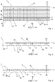
- Fig. 1 is a first layer 5 of a prefabricated component 1 according to the invention (cf. Fig. 4 ) for the production of a blanket 2 (cf. FIG. 7 or FIG. 8 ) shown in supervision.
- the first layer 5 comprises a multiplicity of beam-like or board-shaped wooden elements, each of which extends along a longitudinal direction 4 and, viewed in a second direction 24 that is normal to the longitudinal direction 4, is arranged directly behind one another and connected to one another.
- the wooden elements include wooden elements 3a of a first type and wooden elements 3b of a second type, the wooden elements 3a of the first type and the wooden elements 3b of the second type being arranged alternately one behind the other when viewed in the second direction 24.
- the wood elements 3 a, 3 b are arranged between an upper push wood 19 and a lower push wood 20 or, seen in the second direction 24, the lower push wood 20 forms the beginning of the first layer 5 and the upper push wood 19 the end of the first layer 5.
- the thrust sticks 19, 20 are arranged offset in relation to one another in a third direction 25, the longitudinal direction 4, the second direction 24 and the third direction 25 being mutual stand on each other normally.
- the lower buttwood 20 is flush with an underside 28 of the wooden elements 3a, 3b opposite the upper side 7, cf. Fig. 4 .
- the wooden elements 3a, 3b are joined together by nails 18 (cf. 2 or 3 ) connected (and / or possibly by screws and / or by gluing / gluing), the nails 18 being oriented essentially parallel to the second direction 24.
- the butts 19 and 20 are connected to the wooden elements 3a, 3b by means of partially threaded screws 21 (cf. Fig. 4 ) connected, the partial thread screws 21 being oriented essentially parallel to the second direction 24.
- An upper side 6 of the first layer 5 is formed by upper sides 7 of the wooden elements 3a, 3b.
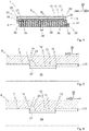
- a second layer 8 of concrete 9 is again arranged on the top 6, cf. e.g. 2 or 3 .
- Recesses are provided on the upper sides 7 of the wooden elements 3a, 3b, which are filled with the concrete 9 of the second layers 8 in order to ensure a shear-resistant connection between the layers 5, 8.
- recesses 10 of a first type and recesses 11 of a second type are provided on the top sides 7 of the wooden elements 3a of the first type.
- only recesses 10 of the first type are provided on the upper sides of the wooden elements 3b of the second type.
- Fig. 5 shows in detail a recess 10 of the first type in a sectional view
- Fig. 6 shows in detail a recess 11 of the second type in a sectional view.
- both the recess 10 of the first type and the recess 11 of the second type have a trapezoidal cross section in a sectional plane that is spanned by the longitudinal direction 4 and the third direction 25.
- the parallel base sides of the respective trapeze are each extended by the top 7 of the each wooden element 3a, 3b and a bottom 12 of the recesses 10, 11 parallel to the upper side 7.
- the bottom 12 is at a distance from the top 7, which can be referred to as the depth 13 of the recesses 10, 11 and is 20 mm in the exemplary embodiment shown.
- the legs of the respective trapezoid are each formed by a first boundary surface 14 and a second boundary surface 15, i.e. the boundary surfaces 14 and 15 delimit the recesses 10, 11 in the longitudinal direction 4 and connect the base 12 to the upper side 7.
- the boundary surfaces 14, 15 are flat, which enables particularly simple manufacture.
- the floor 12 extends with a floor length 27, which in the exemplary embodiment shown is 250 mm.
- Two consecutive recesses in the longitudinal direction 4 typically have a spacing of 400 mm on the respective wooden element 3a, 3b.
- the recesses 10, 11 completely penetrate the respective wooden element 3a, 3b, i.e. over an entire width 26 of the respective wooden element 3a, 3b, the width 26 being 60 mm in the exemplary embodiment shown.
- the recesses 10 of the first type and the recesses 11 of the second type influence the mechanical properties of the component 1 according to the invention in different ways.
- the reason for this are different orientations of the boundary surfaces 14, 15, more precisely different angles 23 which enclose the boundary surfaces 14, 15 with the longitudinal direction 4.
- the first boundary surface 14 and the second boundary surface 15 with the longitudinal direction 4 include angles 23 of equal size, which are greater than 90 °, so that the recess 10 widens along the third direction 25, cf. . Fig. 5 .
- the angle 23 is 100 ° in each case. This results in an optimal and uniform transmission of pressure loads through the concrete 9 or through the second layer 8 to the first layer 5. An optimal pressure load distribution in component 1 is the result.
- the first boundary surface 14 and the second boundary surface 15 include angles 23 of equal size with the longitudinal direction 4, which are smaller than 90 °, so that the recess 11 tapers along the third direction 25, cf. . Fig. 6 .
- the angle 23 is 75 ° in each case.
- the boundary surfaces 14, 15 form, as it were, undercuts which receive the concrete 9 of the second layer 8. This results in a particularly large and uniform form fit, which enables the particularly uniform transmission of higher tensile forces between the two layers 5, 8.
- a particularly uniform distribution of the tensile load in the component 1 according to the invention is hereby achieved, and the second layer 8 is also prevented from being lifted off from the first layer 5.
- the lifting of the second layer 8 from the first layer 5 is additionally prevented in the exemplary embodiment shown by screws 17 which are turned into the top 6 of the first layer 5 and thus each protrude from the top 6 with a section.
- This section is arranged completely in the second layer 8 and brings about a further positive connection of the two layers 5, 8.
- known structural steel mats are arranged as reinforcement 16 in the concrete 9.
- the respective wooden element 3a of the first type has a sequence of recesses as seen in the longitudinal direction 4, the following partial sequence comprises: recess 10 of the first type, recess 11 of the second type, recess 11 of the second type and recess 10 of the first type, cf. Fig. 2 .
- the alternating arrangement of the wooden elements 3a of the first type and the wooden elements 3b of the second type already described above guarantees an optimal distribution of the pressure and tensile loads typically occurring, in particular in the case of ceilings 2, along the second direction 24.
- the ceiling 2 can now be manufactured extremely quickly and easily on the construction site by means of the prefabricated components 1, for which a desired high quality can be guaranteed on the basis of the prefabrication under defined conditions.
- the required span is ensured by a corresponding length of the wooden elements 3a, 3b measured along the longitudinal direction 4.
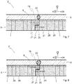
- several components 1 can be arranged one behind the other and connected to one another as seen in the second direction 24.
- two directly successive components 1 with different butt members 19, 20 meet each other, whereby a positive connection between these two components 1 is produced.
- the two abutting components 1 are screwed in the area of the butt members 19, 20.
- the partial thread screws 21 are screwed through the lower butt plate 20 of the second component 1 into the upper butt plate 19 of the first component 1. These partial thread screws 21 are therefore visible from the side of the undersides 28, which is why there is an impact formation in non-visible quality.
- the second layers 8 of the two components 1 are surmounted by the butt pieces 19, 20 parallel to the second direction 24.
- end faces 29, with which the second layers 8 terminate parallel to the second direction 24, have cutouts 30, cf. Fig. 4 . This creates a receiving volume between the mutually opposite end faces 29 of the two components 1, which is closed by means of potting compound 22 in order to complete the ceiling 2.
- Said receiving volume can also be used to screw in the partial thread screws 21, which are provided for screwing the abutting components 1, from the top 7 of the wooden elements 3a, 3b or from the top 6 of the first layer 5.
- This variant is in Fig. 8 illustrated. That is, the partial thread screws 21 are filled with potting compound 22 before the receiving volume is filled, screwed through the receiving volume from above through the upper pushwood 19 of the first component 1 into the lower pushwood 20 of the second component 1. The receiving volume is then filled with casting compound 22.
- the partial thread screws 21 are no longer visible from any side, in particular not from the side of the undersides 28, so that there is an impact formation in visual quality.
Landscapes
- Engineering & Computer Science (AREA)
- Architecture (AREA)
- Physics & Mathematics (AREA)
- Electromagnetism (AREA)
- Civil Engineering (AREA)
- Structural Engineering (AREA)
Claims (10)
- Élément de construction (1) pour la réalisation d'un plafond (2), l'élément de construction (1) comprenant une pluralité d'éléments en bois (3a, 3b) en forme de poutre qui sont disposés parallèlement les uns aux autres et, vus transversalement à une direction longitudinale (4) des éléments en bois (3a, 3b), directement les uns derrière les autres, sont reliés les uns aux autres et forment une première couche (5), dans lequel une face supérieure (6) de la première couche (5) est formée par des faces supérieures (7) des éléments en bois (3a, 3b), dans lequel une deuxième couche (8) en béton (9) est en outre disposée sur la face supérieure (6) de la première couche (5), dans lequel, sur les faces supérieures (7) des éléments en bois (3a, 3b), sont prévus des évidements (10, 11) qui sont remplis par le béton (9) de la deuxième couche (8), dans lequel les évidements (10, 11) présentent chacun un fond (12) qui est espacé d'une profondeur (13) de la face supérieure (7) de l'élément en bois respectif (3a, 3b), dans lequel les évidements (10, 11), vus dans la direction longitudinale (4), sont chacun délimités par une première surface de délimitation (14) et une deuxième surface de délimitation (15) disposée derrière elle,
caractérisé en ce que les évidements comprennent des évidements (10) d'un premier type, la première surface de délimitation (14) et/ou la deuxième surface de délimitation (15) des évidements (10) du premier type formant chacune avec la direction longitudinale (4) un angle (23) qui est supérieur à 90°, de préférence dans la plage de 95° à 120°, particulièrement de préférence dans la plage de 95° à 105°,
que les évidements comprennent en outre des évidements (11) d'un deuxième type, la première surface de délimitation (14) et/ou la deuxième surface de délimitation (15) des évidements (11) du deuxième type formant chacune avec la direction longitudinale (4) un angle (23) qui est inférieur à 90°, de préférence dans la plage de 60° à 85°, particulièrement de préférence dans la plage de 70° à 80°,
que les éléments en bois comprennent en outre des éléments en bois (3a) d'un premier type, les éléments en bois (3a) du premier type présentant à la fois des évidements (10) du premier type et des évidements (11) du deuxième type,
que les éléments en bois comprennent en outre des éléments en bois (3b) d'un deuxième type, les éléments en bois (3b) du deuxième type présentant exclusivement des évidements (10) du premier type,
et que, vu transversalement à la direction longitudinale (4), au moins un élément en bois (3a) du deuxième type est suivi du au moins un élément en bois (3b) du premier type et vice versa. - Élément de construction (1) selon la revendication 1, caractérisé en ce que les évidements (10, 11) présentent chacun une section transversale trapézoïdale dans un plan de coupe, le plan de coupe étant perpendiculaire à la face supérieure (7) de l'élément en bois respectif (3a, 3b) et parallèle à la direction longitudinale (4).
- Élément de construction (1) selon l'une des revendications 1 à 2, caractérisé en ce que la première surface de délimitation (14) et la deuxième surface de délimitation (15) des évidements (10) du premier type forment chacune avec la direction longitudinale (4) un angle (23), de préférence de même grandeur, qui est supérieur à 90°, de préférence dans la plage de 95° à 120°, particulièrement de préférence dans la plage de 95° à 105°.
- Élément de construction (1) selon l'une des revendications 1 à 3, caractérisé en ce que la première surface de délimitation (14) et la deuxième surface de délimitation (15) des évidements (11) du deuxième type forment chacune avec la direction longitudinale (4) un angle (23), de préférence de même grandeur, qui est inférieur à 90°, de préférence dans la plage de 60° à 85°, particulièrement de préférence dans la plage de 70° à 80°.
- Élément de construction (1) selon l'une des revendications 1 à 4, caractérisé en ce que le fond (12) s'étend parallèlement à la direction longitudinale (4).
- Élément de construction (1) selon l'une des revendications 1 à 5, caractérisé en ce que la profondeur (13) se situe dans la plage de 10 mm à 30 mm, de préférence dans la plage de 15 mm à 25 mm.
- Élément de construction (1) selon l'une des revendications 1 à 6, caractérisé en ce que le fond (12) présente une longueur de fond (27) mesurée parallèlement à la direction longitudinale (4) qui se situe dans la plage de 100 mm à 400 mm, de préférence dans la plage de 120 mm à 320 mm.
- Élément de construction (1) selon l'une des revendications 1 à 7, caractérisé en ce que l'élément en bois respectif (3a) du premier type présente, vu dans la direction longitudinale (4), une séquence d'évidements comprenant la séquence partielle suivante : évidement (10) du premier type, évidement (11) du deuxième type, évidement (11) du deuxième type et évidement (10) du premier type.
- Élément de construction (1) selon l'une des revendications 1 à 8, caractérisé en ce que les évidements (10, 11) s'étendent chacun sur toute une largeur totale (26) de l'élément en bois respectif (3a, 3b), la largeur (26) étant mesurée dans une deuxième direction (24) qui est perpendiculaire à la direction longitudinale (4) et parallèle à la face supérieure (7) de l'élément en bois (3a, 3b).
- Élément de construction (1) selon l'une des revendications 1 à 9, caractérisé en ce que des vis (17) sont vissées dans la première couche (5) et dépassent chacune par une partie de la face supérieure (6) de la première couche (5), ladite partie étant disposée entièrement à l'intérieur de la deuxième couche (8) .
Priority Applications (1)
| Application Number | Priority Date | Filing Date | Title |
|---|---|---|---|
| EP18168070.3A EP3556958B1 (fr) | 2018-04-18 | 2018-04-18 | Elément destiné à la production d'une dalle |
Applications Claiming Priority (1)
| Application Number | Priority Date | Filing Date | Title |
|---|---|---|---|
| EP18168070.3A EP3556958B1 (fr) | 2018-04-18 | 2018-04-18 | Elément destiné à la production d'une dalle |
Publications (2)
| Publication Number | Publication Date |
|---|---|
| EP3556958A1 EP3556958A1 (fr) | 2019-10-23 |
| EP3556958B1 true EP3556958B1 (fr) | 2020-06-03 |
Family
ID=62025753
Family Applications (1)
| Application Number | Title | Priority Date | Filing Date |
|---|---|---|---|
| EP18168070.3A Active EP3556958B1 (fr) | 2018-04-18 | 2018-04-18 | Elément destiné à la production d'une dalle |
Country Status (1)
| Country | Link |
|---|---|
| EP (1) | EP3556958B1 (fr) |
Family Cites Families (7)
| Publication number | Priority date | Publication date | Assignee | Title |
|---|---|---|---|---|
| FR667419A (fr) * | 1928-01-19 | 1929-10-16 | Liaison exempte de glissement entre armature en bois et béton dans les constructions en béton à armature en bois | |
| FR2774112B1 (fr) * | 1998-01-27 | 2000-03-17 | Archipente | Element de paroi composite bois-beton |
| ITPC20040010A1 (it) * | 2004-03-31 | 2004-06-30 | Sintesi Srl | Sistema costruttivo per la realizzazione di solai misti in legno e calcestruzzo e relativi componenti per la solidarizzazione dei due materiali |
| AT511220B1 (de) * | 2011-04-08 | 2013-01-15 | Cree Gmbh | Deckenelement zur ausbildung von gebäudedecken |
| DE102013106918B3 (de) * | 2013-07-02 | 2014-05-28 | Bs Ingenieure Ag | Holz-Beton-Verbundkonstruktion |
| DE102016001185A1 (de) * | 2016-02-03 | 2017-08-03 | Lignotrend Gmbh & Co. Kg | Als Holz-Beton-Verbund ausgebildetes Bauelement sowie Verfahren zu dessen Herstellung |
| EP3287570A1 (fr) * | 2016-08-26 | 2018-02-28 | Sebastian Wagner | Élement composite en bois et beton a utiliser comme plafond, plancher ou paroi dans un batiment |
-
2018
- 2018-04-18 EP EP18168070.3A patent/EP3556958B1/fr active Active
Non-Patent Citations (1)
| Title |
|---|
| None * |
Also Published As
| Publication number | Publication date |
|---|---|
| EP3556958A1 (fr) | 2019-10-23 |
Similar Documents
| Publication | Publication Date | Title |
|---|---|---|
| AT511220B1 (de) | Deckenelement zur ausbildung von gebäudedecken | |
| WO1999010613A1 (fr) | Dispositif de renfort pour structures porteuses | |
| DE2128609A1 (de) | Verstärkte Schalungsplatte fur Be tonschalungen | |
| EP3247842B1 (fr) | Poutres de coffrage et construction de coffrage | |
| DE19818525B4 (de) | Holz-Beton-Verbundelement | |
| DE102013109790B4 (de) | Schalungsträger | |
| EP0653005B1 (fr) | Structure porteuse pour etayer des elements de construction plats | |
| EP2989263B1 (fr) | Structure de plafond et bâtiment en bois | |
| EP3067484B1 (fr) | Plaque de bois pour une construction composite en bois/béton, construction composite en bois/béton et leur procédé de fabrication | |
| EP3556958B1 (fr) | Elément destiné à la production d'une dalle | |
| EP2954125B1 (fr) | Construction porteuse en bois comportant un élément porteur en forme de barre ou plat et au moins un deuxième élément porteur en forme de barre ou plat | |
| EP1699986A1 (fr) | Construction de parois en bois, du type a madriers en blocs | |
| CH640591A5 (en) | Wooden trussed girder | |
| EP3105389A1 (fr) | Poutre en bois | |
| DE1481324A1 (de) | Palette | |
| EP2602398B1 (fr) | Cadre en bois | |
| DE2263027A1 (de) | Aus kurzen holzteilen zusammengesetztes bauteil | |
| CH683443A5 (de) | Blockhausartiges Gebäude. | |
| DE202022104305U1 (de) | Holzträger mit Lagenaufbau für einen Schalbelag | |
| EP3130718A1 (fr) | Élement composite de construction | |
| AT2297U1 (de) | Träger aus holz und verfahren zur herstellung eines stegrohlings | |
| AT399008B (de) | Schalung mit tragschienen und schalplatten | |
| EP3741921A1 (fr) | Élément de panneau en bois composé d'une pluralité de madriers | |
| DE1278717B (de) | Hoelzerner Vollwandtraeger und Verbindung | |
| DE20012550U1 (de) | Gebäude, versehen mit einem Bauelement, das eine Zwischenschicht mit zu beiden Seiten derselben angebrachten Aussenschichten umfasst |
Legal Events
| Date | Code | Title | Description |
|---|---|---|---|
| PUAI | Public reference made under article 153(3) epc to a published international application that has entered the european phase |
Free format text: ORIGINAL CODE: 0009012 |
|
| STAA | Information on the status of an ep patent application or granted ep patent |
Free format text: STATUS: REQUEST FOR EXAMINATION WAS MADE |
|
| 17P | Request for examination filed |
Effective date: 20190208 |
|
| AK | Designated contracting states |
Kind code of ref document: A1 Designated state(s): AL AT BE BG CH CY CZ DE DK EE ES FI FR GB GR HR HU IE IS IT LI LT LU LV MC MK MT NL NO PL PT RO RS SE SI SK SM TR |
|
| AX | Request for extension of the european patent |
Extension state: BA ME |
|
| GRAP | Despatch of communication of intention to grant a patent |
Free format text: ORIGINAL CODE: EPIDOSNIGR1 |
|
| STAA | Information on the status of an ep patent application or granted ep patent |
Free format text: STATUS: GRANT OF PATENT IS INTENDED |
|
| RIC1 | Information provided on ipc code assigned before grant |
Ipc: E04B 5/12 20060101AFI20191212BHEP Ipc: E04B 5/38 20060101ALN20191212BHEP Ipc: E04B 5/23 20060101ALN20191212BHEP Ipc: E04C 2/12 20060101ALN20191212BHEP |
|
| INTG | Intention to grant announced |
Effective date: 20200108 |
|
| RIC1 | Information provided on ipc code assigned before grant |
Ipc: E04B 5/23 20060101ALN20191213BHEP Ipc: E04B 5/12 20060101AFI20191213BHEP Ipc: E04B 5/38 20060101ALN20191213BHEP Ipc: E04C 2/12 20060101ALN20191213BHEP |
|
| GRAS | Grant fee paid |
Free format text: ORIGINAL CODE: EPIDOSNIGR3 |
|
| GRAA | (expected) grant |
Free format text: ORIGINAL CODE: 0009210 |
|
| STAA | Information on the status of an ep patent application or granted ep patent |
Free format text: STATUS: THE PATENT HAS BEEN GRANTED |
|
| AK | Designated contracting states |
Kind code of ref document: B1 Designated state(s): AL AT BE BG CH CY CZ DE DK EE ES FI FR GB GR HR HU IE IS IT LI LT LU LV MC MK MT NL NO PL PT RO RS SE SI SK SM TR |
|
| REG | Reference to a national code |
Ref country code: GB Ref legal event code: FG4D Free format text: NOT ENGLISH |
|
| REG | Reference to a national code |
Ref country code: CH Ref legal event code: EP Ref country code: AT Ref legal event code: REF Ref document number: 1277165 Country of ref document: AT Kind code of ref document: T Effective date: 20200615 |
|
| REG | Reference to a national code |
Ref country code: DE Ref legal event code: R096 Ref document number: 502018001574 Country of ref document: DE |
|
| REG | Reference to a national code |
Ref country code: CH Ref legal event code: NV Representative=s name: PATENTANWAELTE SCHAAD, BALASS, MENZL AND PARTN, CH |
|
| REG | Reference to a national code |
Ref country code: LT Ref legal event code: MG4D |
|
| PG25 | Lapsed in a contracting state [announced via postgrant information from national office to epo] |
Ref country code: LT Free format text: LAPSE BECAUSE OF FAILURE TO SUBMIT A TRANSLATION OF THE DESCRIPTION OR TO PAY THE FEE WITHIN THE PRESCRIBED TIME-LIMIT Effective date: 20200603 Ref country code: GR Free format text: LAPSE BECAUSE OF FAILURE TO SUBMIT A TRANSLATION OF THE DESCRIPTION OR TO PAY THE FEE WITHIN THE PRESCRIBED TIME-LIMIT Effective date: 20200904 Ref country code: SE Free format text: LAPSE BECAUSE OF FAILURE TO SUBMIT A TRANSLATION OF THE DESCRIPTION OR TO PAY THE FEE WITHIN THE PRESCRIBED TIME-LIMIT Effective date: 20200603 Ref country code: NO Free format text: LAPSE BECAUSE OF FAILURE TO SUBMIT A TRANSLATION OF THE DESCRIPTION OR TO PAY THE FEE WITHIN THE PRESCRIBED TIME-LIMIT Effective date: 20200903 Ref country code: FI Free format text: LAPSE BECAUSE OF FAILURE TO SUBMIT A TRANSLATION OF THE DESCRIPTION OR TO PAY THE FEE WITHIN THE PRESCRIBED TIME-LIMIT Effective date: 20200603 |
|
| REG | Reference to a national code |
Ref country code: NL Ref legal event code: MP Effective date: 20200603 |
|
| PG25 | Lapsed in a contracting state [announced via postgrant information from national office to epo] |
Ref country code: RS Free format text: LAPSE BECAUSE OF FAILURE TO SUBMIT A TRANSLATION OF THE DESCRIPTION OR TO PAY THE FEE WITHIN THE PRESCRIBED TIME-LIMIT Effective date: 20200603 Ref country code: HR Free format text: LAPSE BECAUSE OF FAILURE TO SUBMIT A TRANSLATION OF THE DESCRIPTION OR TO PAY THE FEE WITHIN THE PRESCRIBED TIME-LIMIT Effective date: 20200603 Ref country code: LV Free format text: LAPSE BECAUSE OF FAILURE TO SUBMIT A TRANSLATION OF THE DESCRIPTION OR TO PAY THE FEE WITHIN THE PRESCRIBED TIME-LIMIT Effective date: 20200603 Ref country code: BG Free format text: LAPSE BECAUSE OF FAILURE TO SUBMIT A TRANSLATION OF THE DESCRIPTION OR TO PAY THE FEE WITHIN THE PRESCRIBED TIME-LIMIT Effective date: 20200903 |
|
| PG25 | Lapsed in a contracting state [announced via postgrant information from national office to epo] |
Ref country code: AL Free format text: LAPSE BECAUSE OF FAILURE TO SUBMIT A TRANSLATION OF THE DESCRIPTION OR TO PAY THE FEE WITHIN THE PRESCRIBED TIME-LIMIT Effective date: 20200603 Ref country code: NL Free format text: LAPSE BECAUSE OF FAILURE TO SUBMIT A TRANSLATION OF THE DESCRIPTION OR TO PAY THE FEE WITHIN THE PRESCRIBED TIME-LIMIT Effective date: 20200603 |
|
| PG25 | Lapsed in a contracting state [announced via postgrant information from national office to epo] |
Ref country code: CZ Free format text: LAPSE BECAUSE OF FAILURE TO SUBMIT A TRANSLATION OF THE DESCRIPTION OR TO PAY THE FEE WITHIN THE PRESCRIBED TIME-LIMIT Effective date: 20200603 Ref country code: RO Free format text: LAPSE BECAUSE OF FAILURE TO SUBMIT A TRANSLATION OF THE DESCRIPTION OR TO PAY THE FEE WITHIN THE PRESCRIBED TIME-LIMIT Effective date: 20200603 Ref country code: PT Free format text: LAPSE BECAUSE OF FAILURE TO SUBMIT A TRANSLATION OF THE DESCRIPTION OR TO PAY THE FEE WITHIN THE PRESCRIBED TIME-LIMIT Effective date: 20201006 Ref country code: ES Free format text: LAPSE BECAUSE OF FAILURE TO SUBMIT A TRANSLATION OF THE DESCRIPTION OR TO PAY THE FEE WITHIN THE PRESCRIBED TIME-LIMIT Effective date: 20200603 Ref country code: EE Free format text: LAPSE BECAUSE OF FAILURE TO SUBMIT A TRANSLATION OF THE DESCRIPTION OR TO PAY THE FEE WITHIN THE PRESCRIBED TIME-LIMIT Effective date: 20200603 Ref country code: IT Free format text: LAPSE BECAUSE OF FAILURE TO SUBMIT A TRANSLATION OF THE DESCRIPTION OR TO PAY THE FEE WITHIN THE PRESCRIBED TIME-LIMIT Effective date: 20200603 Ref country code: SM Free format text: LAPSE BECAUSE OF FAILURE TO SUBMIT A TRANSLATION OF THE DESCRIPTION OR TO PAY THE FEE WITHIN THE PRESCRIBED TIME-LIMIT Effective date: 20200603 |
|
| PG25 | Lapsed in a contracting state [announced via postgrant information from national office to epo] |
Ref country code: PL Free format text: LAPSE BECAUSE OF FAILURE TO SUBMIT A TRANSLATION OF THE DESCRIPTION OR TO PAY THE FEE WITHIN THE PRESCRIBED TIME-LIMIT Effective date: 20200603 Ref country code: SK Free format text: LAPSE BECAUSE OF FAILURE TO SUBMIT A TRANSLATION OF THE DESCRIPTION OR TO PAY THE FEE WITHIN THE PRESCRIBED TIME-LIMIT Effective date: 20200603 Ref country code: IS Free format text: LAPSE BECAUSE OF FAILURE TO SUBMIT A TRANSLATION OF THE DESCRIPTION OR TO PAY THE FEE WITHIN THE PRESCRIBED TIME-LIMIT Effective date: 20201003 |
|
| REG | Reference to a national code |
Ref country code: DE Ref legal event code: R097 Ref document number: 502018001574 Country of ref document: DE |
|
| PLBE | No opposition filed within time limit |
Free format text: ORIGINAL CODE: 0009261 |
|
| STAA | Information on the status of an ep patent application or granted ep patent |
Free format text: STATUS: NO OPPOSITION FILED WITHIN TIME LIMIT |
|
| PG25 | Lapsed in a contracting state [announced via postgrant information from national office to epo] |
Ref country code: DK Free format text: LAPSE BECAUSE OF FAILURE TO SUBMIT A TRANSLATION OF THE DESCRIPTION OR TO PAY THE FEE WITHIN THE PRESCRIBED TIME-LIMIT Effective date: 20200603 |
|
| 26N | No opposition filed |
Effective date: 20210304 |
|
| PG25 | Lapsed in a contracting state [announced via postgrant information from national office to epo] |
Ref country code: MC Free format text: LAPSE BECAUSE OF FAILURE TO SUBMIT A TRANSLATION OF THE DESCRIPTION OR TO PAY THE FEE WITHIN THE PRESCRIBED TIME-LIMIT Effective date: 20200603 |
|
| PG25 | Lapsed in a contracting state [announced via postgrant information from national office to epo] |
Ref country code: LU Free format text: LAPSE BECAUSE OF NON-PAYMENT OF DUE FEES Effective date: 20210418 |
|
| REG | Reference to a national code |
Ref country code: BE Ref legal event code: MM Effective date: 20210430 |
|
| PG25 | Lapsed in a contracting state [announced via postgrant information from national office to epo] |
Ref country code: FR Free format text: LAPSE BECAUSE OF NON-PAYMENT OF DUE FEES Effective date: 20210430 |
|
| PG25 | Lapsed in a contracting state [announced via postgrant information from national office to epo] |
Ref country code: IE Free format text: LAPSE BECAUSE OF NON-PAYMENT OF DUE FEES Effective date: 20210418 |
|
| PG25 | Lapsed in a contracting state [announced via postgrant information from national office to epo] |
Ref country code: IS Free format text: LAPSE BECAUSE OF FAILURE TO SUBMIT A TRANSLATION OF THE DESCRIPTION OR TO PAY THE FEE WITHIN THE PRESCRIBED TIME-LIMIT Effective date: 20201003 |
|
| PG25 | Lapsed in a contracting state [announced via postgrant information from national office to epo] |
Ref country code: BE Free format text: LAPSE BECAUSE OF NON-PAYMENT OF DUE FEES Effective date: 20210430 |
|
| P01 | Opt-out of the competence of the unified patent court (upc) registered |
Effective date: 20230426 |
|
| PG25 | Lapsed in a contracting state [announced via postgrant information from national office to epo] |
Ref country code: CY Free format text: LAPSE BECAUSE OF FAILURE TO SUBMIT A TRANSLATION OF THE DESCRIPTION OR TO PAY THE FEE WITHIN THE PRESCRIBED TIME-LIMIT Effective date: 20200603 |
|
| PG25 | Lapsed in a contracting state [announced via postgrant information from national office to epo] |
Ref country code: HU Free format text: LAPSE BECAUSE OF FAILURE TO SUBMIT A TRANSLATION OF THE DESCRIPTION OR TO PAY THE FEE WITHIN THE PRESCRIBED TIME-LIMIT; INVALID AB INITIO Effective date: 20180418 |
|
| PG25 | Lapsed in a contracting state [announced via postgrant information from national office to epo] |
Ref country code: SI Free format text: LAPSE BECAUSE OF FAILURE TO SUBMIT A TRANSLATION OF THE DESCRIPTION OR TO PAY THE FEE WITHIN THE PRESCRIBED TIME-LIMIT Effective date: 20200603 |
|
| PG25 | Lapsed in a contracting state [announced via postgrant information from national office to epo] |
Ref country code: MK Free format text: LAPSE BECAUSE OF FAILURE TO SUBMIT A TRANSLATION OF THE DESCRIPTION OR TO PAY THE FEE WITHIN THE PRESCRIBED TIME-LIMIT Effective date: 20200603 |
|
| PG25 | Lapsed in a contracting state [announced via postgrant information from national office to epo] |
Ref country code: TR Free format text: LAPSE BECAUSE OF FAILURE TO SUBMIT A TRANSLATION OF THE DESCRIPTION OR TO PAY THE FEE WITHIN THE PRESCRIBED TIME-LIMIT Effective date: 20200603 |
|
| PG25 | Lapsed in a contracting state [announced via postgrant information from national office to epo] |
Ref country code: MT Free format text: LAPSE BECAUSE OF FAILURE TO SUBMIT A TRANSLATION OF THE DESCRIPTION OR TO PAY THE FEE WITHIN THE PRESCRIBED TIME-LIMIT Effective date: 20200603 |
|
| PGFP | Annual fee paid to national office [announced via postgrant information from national office to epo] |
Ref country code: GB Payment date: 20250313 Year of fee payment: 8 |
|
| PGFP | Annual fee paid to national office [announced via postgrant information from national office to epo] |
Ref country code: DE Payment date: 20250425 Year of fee payment: 8 |
|
| PGFP | Annual fee paid to national office [announced via postgrant information from national office to epo] |
Ref country code: CH Payment date: 20250501 Year of fee payment: 8 |
|
| PGFP | Annual fee paid to national office [announced via postgrant information from national office to epo] |
Ref country code: AT Payment date: 20250416 Year of fee payment: 8 |