EP3556632A1 - Spannhebel zur gelenkfixierung eines schienenfahrzeugs - Google Patents
Spannhebel zur gelenkfixierung eines schienenfahrzeugs Download PDFInfo
- Publication number
- EP3556632A1 EP3556632A1 EP19162789.2A EP19162789A EP3556632A1 EP 3556632 A1 EP3556632 A1 EP 3556632A1 EP 19162789 A EP19162789 A EP 19162789A EP 3556632 A1 EP3556632 A1 EP 3556632A1
- Authority
- EP
- European Patent Office
- Prior art keywords
- clamping
- lever
- jaw
- rail vehicle
- shell
- Prior art date
- Legal status (The legal status is an assumption and is not a legal conclusion. Google has not performed a legal analysis and makes no representation as to the accuracy of the status listed.)
- Granted
Links
Images
Classifications
-
- B—PERFORMING OPERATIONS; TRANSPORTING
- B61—RAILWAYS
- B61G—COUPLINGS; DRAUGHT AND BUFFING APPLIANCES
- B61G5/00—Couplings for special purposes not otherwise provided for
- B61G5/02—Couplings for special purposes not otherwise provided for for coupling articulated trains, locomotives and tenders or the bogies of a vehicle; Coupling by means of a single coupling bar; Couplings preventing or limiting relative lateral movement of vehicles
Definitions
- the invention relates to a tensioning lever for joint fixation in a rail vehicle.
- devices for joint fixation must be screwed or plugged to the car parts in alignment processes in a single track case, ie in particular the so-called stretching or buckling of the car parts to the track, with the help of the articulated connection between the car parts is fixed.
- These devices may also be referred to as tension levers.
- tension levers For example, by means of a threaded rod which is stretched between two clamping levers on adjacent carriage parts, the carriage parts can then be aligned with each other.
- corresponding complementary shots were provided to the car bodies of the vehicles, for example, plug-in tubes or tabs with eyes that were self-welded and otherwise permanently carried.
- steering wheel claws or steering wheel crutches for theft prevention of motor vehicles, which prevent by attaching a rotation of the steering wheel, are well known.
- the invention has for its object to provide a simplified device for railing of rail vehicles.
- a tensioning lever according to the invention comprises a first jaw and at least one further, second jaw, wherein at least one of the jaws is movably and lockably arranged on the tensioning lever in order to clamp the tensioning lever to a body of the rail vehicle.
- the tensioning lever is used for joint fixation in a rail vehicle, especially in a single rail. He is suitably trained and dimensioned.
- its force-transmitting parts are made of a metal or a metal alloy.
- the claws are suitably adapted for engaging in and for clamping the clamping lever in a shell of a rail vehicle, for example in a subframe or a joint end support of a car body of the rail vehicle, in particular in a suitable complementarily shaped cavity or opening in Shell of the rail vehicle.
- the tensioning lever according to the invention can be easily attached to a square profile of the vehicle with its universal form-fitting claws with lockable stop. It is simply clamped under the vehicle in suitable existing openings in the shell and locked and is thus suitable for several vehicle variants.
- a rail vehicle according to the invention in particular of the low-floor multi-articulated trolley type, is free from separate, provided receptacles for fastening complementarily designed clamping levers for joint fixation.
- the rail vehicle has only a conventional shell in differential construction, for example, in which square profiles or sheets welded to a frame construction are.
- the clamping lever is inserted into suitable existing openings in the shell, clamped and locked.
- the term of the tensioning lever does not refer to the shape of the device in the region of the claws, but to its actual function in the single-rail process, namely an impressed from outside on the clamping lever force on the car body, for example, to transmit the joint end support or the base of the rail vehicle to move it in a predetermined direction or to align and / or fix this relative to an adjacent car body.
- the claws can be arranged on a common axis, wherein the second claw is displaceable along the axis.
- the clamping lever may be formed such that at least the second jaw is mechanically, pneumatically, hydraulically or electrically movable and / or lockable. In order to jam the clamping lever, so a force is mechanically, pneumatically, hydraulically or electrically generated and optionally impressed from outside on at least the second jaw.
- the claws are arranged in a first portion of the clamping lever, which first portion ends in the region of a first end of the clamping lever, wherein the clamping lever in a second end opposite the first end, a displacement device and / or a device for locking at least the second Claw has.
- a displacement and / or locking and releasing the locking of at least the second jaw from the second end of the clamping lever forth is possible and thus of a freely accessible in the assembled state of the clamping lever end of the clamping lever.
- the clamping lever may optionally have at the second end a device for fastening a connecting member.
- the tensioning lever could act as Telescope tube with at least a first part of the tube and a slidably guided in the first part of the tube, in particular coaxial rod be formed, wherein the first jaw is fixedly connected to the first sub-tube and the second jaw fixed to the rod.
- the rod could then at least partially protrude from the second end of the sub-tube and be displaced by train or thrust on the protruding part of the rod relative to the first sub-tube.
- the second jaw is movable relative to the first jaw by applying an external force.
- the rod would then be lockable, for example, by means of a clamping screw, which is guided by a threaded bore in the first sub-tube and by means of which a force on the rod for clamping the rod relative to the first sub-tube can be applied.
- the clamping screw is then in turn advantageously arranged in the region of the second end of the clamping lever and thus freely accessible in the assembled state of the clamping lever from the outside.
- the tensioning lever may be formed with a first sub-tube having an internal thread and a threaded rod guided in the first sub-tube, which is displaceable relative to the first sub-tube by rotation at the free end protruding from the first sub-tube.
- the thread brings a self-locking, so that an additional device for locking could be omitted.
- lock nut could be provided for locking.
- the first jaw would be firmly connected to the first sub-tube and the second claw would be fixed in the axial direction with a threaded rod.
- Other solutions with racks etc. would be conceivable.
- At least the first jaw is arranged at the first end of the clamping lever, in particular at a first end of the first sub-tube, wherein the clamping lever at a second end opposite the first end, in particular at a second end the first part of the tube, a device for fixing a connecting member has.
- the connecting member is a spreading or pulling device, for example a threaded rod. It is mounted between two identical, identical or similar clamping levers, which in turn are mounted on opposite sides of adjacent car bodies of a rail vehicle. By means of the connecting member forces are then exerted on their associated clamping levers, which lead to an alignment of the two car bodies of the rail vehicle by the forces are transmitted via the respective clamping lever in the respective car bodies of the rail vehicle and these according to each other or away from each other move.
- a first tensioning lever on the shell of the first car body of the rail vehicle by moving at least the second claw to rest on the shell moved at the same time invest the first claw on the shell and applied a force against the equipment and locked at least the second claw against further movement.
- the same process is repeated analogously on the opposite side of the second car body with the second clamping lever, so that it is braced with the second car body.
- the free ends of the first and the second clamping lever are connected to a connecting member and applied with the connecting member, a force for aligning the first and the second car body respectively on the tensioning lever associated with it.
- a connecting member a threaded rod can be used, which applies the forces by stretching or compressing the threaded rod and thus move toward one another - or away from one another the forces associated with the clamping levers sides of the opposite car bodies of the vehicle enforces.
- the clamping levers are arranged on one and the same side of the adjacent car bodies. In order to achieve a complete fixation of the joint between the car bodies, the same process can take place on the opposite side of the car bodies.
- a further development of the clamping lever according to the invention provides that the claws are aligned facing away from each other.
- the tensioning lever would thus be braced by the fact that the at least one movable second claw away from the first claw and thus moved to a frame profile of the shell of the vehicle and comes into abutment with this, while the first claw on with this opposite frame profile of the shell of the vehicle is in abutment.
- the clamping lever is then clamped in an opening in the shell of the vehicle and thus between two shell components.
- the claws could be directed towards each other.
- a sheet or a beam of the shell would be stretched between the jaws of the clamping lever by at least the at least one movable second jaw is moved toward the first jaw.
- the claws are advantageously complementary to the shell, in particular formed to the thicknesses of the sheets of the shell. You may be rounded to the shell side facing to grab in corners or cone-shaped to equally clamp different sheet metal thicknesses can. According to one embodiment, they can also be designed to be adjustable perpendicular to the axis or to the displaceability of the second jaw, in order to be able to clamp different sheet metal thicknesses.
- the tensioning lever would be designed to be predominantly elongated, wherein the claws are arranged on an axis and at least the second claw is displaceable along the axis.
- the clamping lever could alternatively also have a plate shape at least in the area of the claws.
- a shell component could also be clamped or the clamping lever could be clamped in a shell opening.
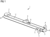
- Fig. 1 an inventive clamping lever 1 for clamping and locking in an opening of a frame structure of a car body of a rail vehicle is shown.
- the clamping lever 1 is telescopically formed and comprises a first sub-tube 11, in which a rod 8 is mounted axially displaceable.
- the first jaw 2 is fixedly connected to the first sub-tube 11 at a first end 6 of the first sub-tube 11 and thus at a first end 6 of the clamping lever 1.
- the second jaw 3 is fixedly connected to the rod 8, so that a displacement of the rod 8 leads to a displacement of the second claw 3. Accordingly, a Slot 9 is provided in the first sub-tube 11 for guiding the second jaw 3.
- the displacement can be impressed from the outside by pulling on a part of the rod 8 projecting from the second end 7 of the first sub-tube 11 opposite the first end 6 of the first sub-tube 11.
- the jaws 2, 3 moving away from one another can be braced against one another in the opening of the frame structure of the car body of the rail vehicle.
- the tension would be released again.
- a shell component could be clamped between the two jaws, which may then be aligned with each other.
- a device for locking at least the second jaw 3 is provided - here a clamping screw 5 for locking the rod 8 to the first sub-tube 11.
- the clamping screw 5 is in the region of the second End 7 of the first sub-tube 11 is arranged, which is freely accessible in the assembled state of the clamping lever 1, while the area is clamped to the claws 2, 3 in the shell.
- clamping lever 1 in the region of the second end at least one device for fixing a connecting member on the clamping lever, here as two eyelets 4 and 4 'is formed.
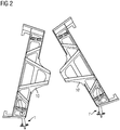
- a clamping lever 1 are mounted on each side of the car adjacent car bodies on the opposite end sides, so a total of four tension levers. Illustrated is in Fig. 2 only one side of the car.
- the clamping levers 1 and 1 ' are correspondingly in openings at the respective joint end supports 10 and 10' of the respective car bodies of the rail vehicle braced.
- a connecting member such as a threaded rod, with the eyelets 4 or 4 'of the clamping levers 1 and 1' connected and the clamping levers 1 and 1 'by means of the connecting member pulled toward each other or pushed away from each other and thus the car bodies on the corresponding side of the car moved or spread apart.
Landscapes
- Engineering & Computer Science (AREA)
- Mechanical Engineering (AREA)
- Clamps And Clips (AREA)
- Vehicle Cleaning, Maintenance, Repair, Refitting, And Outriggers (AREA)
- Mutual Connection Of Rods And Tubes (AREA)
Abstract
Description
- Die Erfindung betrifft einen Spannhebel zur Gelenkfixierung bei einem Schienenfahrzeug.
- Bei mehrgliedrigen Schienenfahrzeugen, beispielsweise Niederflurfahrzeugen, müssen bei Ausrichtvorgängen im Eingleisungsfall, also insbesondere beim sogenannten Strecken oder Knicken der Wagenteile zum Gleis, Vorrichtungen zur Gelenkfixierung an die Wagenteile geschraubt oder gesteckt werden, mit deren Hilfe die gelenkige Verbindung zwischen den Wagenteilen fixiert wird. Diese Vorrichtungen können auch als Spannhebel bezeichnet werden. Beispielsweise mittels einer Gewindestange, die zwischen zwei Spannhebeln an benachbarten Wagenteilen gespannt wird, können die Wagenteile dann zueinander ausgerichtet werden. Zur sicheren Befestigung dieser Spannhebel wurden an den Wagenkästen der Fahrzeuge entsprechend komplementäre Aufnahmen vorgesehen, beispielsweise Einsteckrohre oder Laschen mit Augen, die selbst eingeschweißt und anderweitig dauerhaft mitgeführt wurden.
- Darüber hinaus sind sogenannte Lenkradkrallen oder Lenkradkrücken zur Diebstahlsicherung von Kraftfahrzeugen, die durch Anbringen ein Verdrehen des Lenkrads verhindern, allgemein bekannt.
- Der Erfindung liegt die Aufgabe zugrunde, eine vereinfachte Vorrichtung zum Eingleisen von Schienenfahrzeugen anzugeben.
- Gelöst wird die Aufgabe durch die Gegenstände der unabhängigen Patentansprüche 1 und 9. Weiterbildungen und Ausgestaltungen der Erfindung finden sich in den Merkmalen der abhängigen Patentansprüche wieder.
- Ein erfindungsgemäßer Spannhebel umfasst eine erste Klaue und wenigstens eine weitere, zweite Klaue aufweist, wobei wenigstens eine der Klauen beweglich und arretierbar am Spannhebel angeordnet ist, um den Spannhebel mit einem Wagenkasten des Schienenfahrzeugs zu verspannen. Der Spannhebel dient zur Gelenkfixierung bei einem Schienenfahrzeug, insbesondere bei einer Eingleisung. Er ist entsprechend geeignet ausgebildet und dimensioniert. Beispielsweise sind seine kraftübertragenden Teile aus einem Metall oder einer Metalllegierung gefertigt. Die Klauen, gelegentlich auch als Krallen bezeichnet, sind entsprechend geeignet ausgebildet zum Eingreifen in und zum Verspannen des Spannhebels in einem Rohbau eines Schienenfahrzeugs, beispielsweise in einem Untergestell oder einem Gelenkendträger eines Wagenkastens des Schienenfahrzeugs, insbesondere in einem geeigneten, komplementär ausgebildeten Hohlraum oder Öffnung im Rohbau des Schienenfahrzeugs.
- Der erfindungsgemäße Spannhebel lässt sich mit seinen universell formschlüssig ausgeführten Klauen mit arretierbaren Anschlag leicht an einem Vierkantprofil des Fahrzeugs befestigen. Er wird einfach unter dem Fahrzeug in geeignete vorhandene Öffnungen im Rohbau eingeklemmt und arretiert und ist somit passend für mehrere Fahrzeugvarianten.
- Weitere Vorteile der erfindungsgemäßen Vorrichtung sind insbesondere eine Kosten- und Gewichtseinsparung durch den Wegfall von dauerhaft eingeschweißten Verstärkungen oder Aufnahmen sowie die Einsparung von Konstruktions- und Fertigungsstunden durch den Wegfall der sonst üblichen Aufnahmen an jedem Fahrzeug. Zusätzlich wird ein sicheres Arbeiten des Personals beim Eingleisungsvorgang neben dem Fahrzeug ermöglicht, anstelle unter das Fahrzeug greifen zu müssen.
- So ist ein erfindungsgemäßes Schienenfahrzeug, insbesondere vom Typ Niederflur-Multigelenkwagen, frei von gesonderten, dafür vorgesehenen Aufnahmen zur Befestigung von komplementär ausgebildeten Spannhebeln zur Gelenkfixierung. Das Schienenfahrzeug weist lediglich einen herkömmlichen Rohbau in Differentialbauweise auf, beispielsweise in welchem Vierkant-Profile oder Bleche zu einer Rahmenkonstruktion verschweißt sind. Der Spannhebel wird in geeignete vorhandene Öffnungen im Rohbau eingeführt, verspannt und arretiert.
- Der Begriff des Spannhebels bezieht sich dabei nicht auf die Form der Vorrichtung im Bereich der Krallen, sondern auf seine eigentliche Funktion im Eingleisungsprozess, nämlich eine von außen auf den Spannhebel aufgeprägt Kraft auf den Wagenkasten, beispielsweise den Gelenkendträger oder das Untergestell, des Schienenfahrzeugs zu übertragen, um diesen in eine vorgegebene Richtung zu bewegen bzw. diesen relativ zu einem benachbarten Wagenkasten auszurichten und/oder zu fixieren.
- Gemäß einer Weiterbildung der Erfindung können die Klauen auf einer gemeinsamen Achse angeordnet sein, wobei die zweite Klaue entlang der Achse verschiebbar ist. Dabei kann der Spannhebel derart ausgebildet sein, dass wenigstens die zweite Klaue mechanisch, pneumatisch, hydraulisch oder elektrisch bewegbar ist und/oder arretierbar ist. Um den Spannhebel zu verklemmen, wird also eine Kraft mechanisch, pneumatisch, hydraulisch oder elektrisch erzeugt und gegebenenfalls von außen auf wenigstens die zweite Klaue aufgeprägt.
- Beispielsweise sind die Klauen in einem ersten Abschnitt des Spannhebels angeordnet, welcher erste Abschnitt im Bereich eines ersten Endes des Spannhebels endet, wobei der Spannhebel in einem dem ersten Ende gegenüberliegenden, zweiten Ende eine Vorrichtung zur Verschiebung und/oder eine Vorrichtung zur Arretierung wenigstens der zweiten Klaue aufweist. Somit ist eine Verschiebung und/oder Arretierung sowie das Lösen der Arretierung wenigstens der zweiten Klaue vom zweiten Ende des Spannhebels her möglich und somit von einem im montierten Zustand des Spannhebels frei zugänglichen Ende des Spannhebels. Darüber hinaus kann der Spannhebel am zweiten Ende gegebenenfalls eine Vorrichtung zur Befestigung eines Verbindungsorgans aufweisen.
- Vorrichtungen zur Verschiebung und/oder Arretierung sind dem Fachmann bekannt. So könnte der Spannhebel beispielsweise als Teleskoprohr mit wenigstens einer ersten Teilröhre und einer in der ersten Teilröhre verschiebbar geführten, insbesondere koaxialen Stange ausgebildet sein, wobei die erste Klaue fest mit der ersten Teilröhre und die zweite Klaue fest mit der Stange verbunden ist. Die Stange könnte dann zumindest teilweise aus dem zweiten Ende der Teilröhre ragen und durch Zug oder Schub am herausragenden Teil der Stange relativ zur ersten Teilröhre verschoben werden. Somit ist auch die zweite Klaue relativ zur ersten Klaue durch Aufbringen einer äußeren Kraft bewegbar.
- Arretierbar wäre die Stange dann beispielsweise mittels einer Festklemmschraube, die durch eine Gewindebohrung in der ersten Teilröhre geführt ist und mittels welcher eine Kraft auf die Stange zum Festklemmen der Stange relativ zur ersten Teilröhre aufbringbar ist. Die Festklemmschraube ist dann wiederum vorteilhaft im Bereich des zweiten Endes des Spannhebels angeordnet und damit im montierten Zustand des Spannhebels frei von außen zugänglich.
- Alternativ kann der Spannhebel eine erste Teilröhre mit Innengewinde und eine in der ersten Teilröhre geführten Gewindestange ausgebildet sein, die durch Drehung am freien, aus der ersten Teilröhre herausragenden Ende relativ zur ersten Teilröhre verschiebbar ist. Das Gewinde bringt eine Selbsthemmung mit, so dass eine zusätzliche Vorrichtung zur Arretierung entfallen könnte. Zusätzlich könnte aber Kontermutter zur Arretierung vorgesehen sein. Auch in dieser Ausführungsform wäre die erste Klaue fest mit der ersten Teilröhre verbunden und die zweite Klaue wäre in axialer Richtung fest mit einer Gewindestange verbunden. Weitere Lösungen mit Zahnstangen etc. wären denkbar.
- Gemäß einer weiteren, allgemeineren Weiterbildung ist wenigstens die erste Klaue am ersten Ende des Spannhebels, insbesondere an einem ersten Ende der ersten Teilröhre, angeordnet, wobei der Spannhebel an einem dem ersten Ende gegenüberliegenden zweiten Ende, insbesondere an einem zweiten Ende der ersten Teilröhre, eine Vorrichtung zur Befestigung eines Verbindungsorgans aufweist.
- Das Verbindungsorgan ist eine Spreiz- oder Zugvorrichtung, z.B eine Gewindestange. Sie wird zwischen zwei identischen, baugleichen oder ähnlichen Spannhebeln montiert, die ihrerseits an sich gegenüberliegenden Seiten von benachbarten Wagenkästen eines Schienenfahrzeugs montiert sind. Mittels des Verbindungsorgans werden dann Kräfte auf die mit ihr in Verbindung stehenden Spannhebeln ausgeübt, die zu einer Ausrichtung der beiden Wagenkästen des Schienenfahrzeugs führen, indem die Kräfte über die jeweiligen Spannhebel in auf die jeweiligen Wagenkästen des Schienenfahrzeugs übertragen werden und diese entsprechend zueinander oder voneinander weg bewegen.
- Zur Fixierung eines Gelenks zwischen zwei benachbarten Wagenkästen eines Schienenfahrzeugs, insbesondere bei einer Eingleisung eines entgleisten Schienenfahrzeugs, beispielsweise eines Multigelenkwagens unter Verwendung von wenigstens zwei Spannhebeln wird ein erster Spannhebel am Rohbau des ersten Wagenkastens des Schienenfahrzeugs durch Bewegen zumindest der zweiten Klaue bis zur Anlage am Rohbau bei gleichzeitiger Anlage der ersten Klaue am Rohbau bewegt und eine Kraft entgegen der Anlagen aufgebracht sowie zumindest die zweite Klaue gegen weitere Bewegung arretiert. Derselbe Vorgang wird analog auf der gegenüberliegenden Seite des zweiten Wagenkastens mit dem zweiten Spannhebels wiederholt, so dass dieser mit dem zweiten Wagenkasten verspannt ist. Anschließend werden die freien Enden des ersten und des zweiten Spannhebels mit einem Verbindungsorgan verbunden und mit des Verbindungsorgans eine Kraft zur Ausrichtung des ersten und des zweiten Wagenkastens jeweils auf die mit ihr verbundenen Spannhebel aufgebracht. Zuvor müssen die Spanhebel natürlich noch in den Rohbau eingeführt und grob ausgerichtet werden. Als Verbindungsorgan kann eine Gewindestange Verwendung finden, die die Kräfte durch strecken oder stauchen der Gewindestange aufbringt und somit ein aufeinander zu - oder voneinander wegbewegen der mit den Spannhebeln verbundenen Seiten der gegenüberliegenden Wagenkästen des Fahrzeugs erzwingt. Die Spannhebel werden auf ein und derselben Seite der benachbarten Wagenkästen angeordnet. Um eine vollständige Fixierung des Gelenks zwischen den Wagenkästen zu erreichen, kann derselbe Vorgang auf der gegenüberliegenden Seite der Wagenkästen erfolgen.
- Eine weitere Weiterbildung des erfindungsgemäßen Spannhebels sieht vor, dass die Klauen voneinander weg weisend ausgerichtet sind. Der Spannhebel würde also dadurch verspannt, dass die wenigstens eine bewegliche zweite Klaue von der ersten Klaue weg- und damit auf ein Rahmenprofil des Rohbaus des Fahrzeugs zubewegt wird und mit diesem in Anschlag kommt, während die erste Klaue auf mit einem diesem gegenüberliegenden Rahmenprofil des Rohbaus des Fahrzeugs in Anschlag ist. Der Spannhebel wird sodann in eine Öffnung im Rohbau des Fahrzeugs und somit zwischen zwei Rohbauteile verspannt. Umgekehrt könnten die Klauen aufeinander zu gerichtet sein. Dann wiederum würde ein Blech oder ein Balken des Rohbaus zwischen die Klauen des Spannhebels gespannt, indem zumindest die wenigstens eine bewegliche zweite Klaue auf die erste Klaue zubewegt wird.
- Die Klauen sind vorteilhaft komplementär zum Rohbau, insbesondere zu den Dicken der Bleche des Rohbaus ausgebildet. Sie können auf den Rohbau zugewandten Seite abgerundet sein, um in Ecken zu greifen oder kegelförmig ausgebildet sein, um gleichermaßen verschiedene Blechdicken einspannen zu können. Gemäß einer Ausführungsform können sie auch senkrecht zur Achse bzw. zur Verschiebbarkeit der zweiten Klaue verstellbar ausgebildet sein, um verschiedene Blechdicken einspannen zu können.
- Gemäß den bislang beschriebenen Ausführungsformen wäre der Spannhebel vornehmlich länglich ausgebildet, wobei die Klauen auf einer Achse angeordnet sind und zumindest die zweite Klaue entlang der Achse verschiebbar ist. Dies entspricht der Ausbildung gemäß einer sogenannten Lenkradkralle. Der Spannhebel könnte jedoch alternativ auch zumindest im Bereich der Klauen eine Tellerform aufweisen. Dort könnten mehrere, insbesondere wenigstens drei Krallen, beispielsweise konzentrisch angeordnet und jeweils radial beweglich angeordnet sein. Somit ließe sich ebenfalls ein Rohbauteil einspannen oder der Spannhebel ließe sich in eine Rohbauöffnung einspannen.
- Die Erfindung lässt zahlreiche Ausführungsformen zu. Sie wird anhand der nachfolgenden Figuren näher erläutert, in denen jeweils ein Ausgestaltungsbeispiel dargestellt ist. Gleiche Elemente in den Figuren sind mit gleichen Bezugszeichen versehen.
- Fig. 1
- zeigt schematisch einen erfindungsgemäßen Spannhebel,
- Fig. 2
- zeigt schematisch Teile der Untergestelle von gegenüberliegenden Wagenkästen eines Multigelenk-Schienenfahrzeugs mit dort montierten (eingeklemmten und arretierten) Spannhebeln.
- In
Fig. 1 ist ein erfindungsgemäßer Spannhebel 1 zum Einklemmen und Arretieren in einer Öffnung einer Rahmenstruktur eines Wagenkastens eines Schienenfahrzeugs dargestellt. - Hierzu weist er wenigstens zwei voneinander wegweisend gerichtete Klauen 2, 3 auf, wobei die zweite Klaue 3 entlang des Spannhebels 1 zumindest ein Stück entlang des Spannhebels 1 axial verschiebbar und arretierbar angebracht ist. Der Spannhebel 1 ist teleskopartig ausgebildet und umfasst eine erste Teilröhre 11, in welcher eine Stange 8 axial verschiebbar gelagert ist. Die erste Klaue 2 ist an einem ersten Ende 6 der ersten Teilröhre 11 und damit an einem ersten Ende 6 des Spannhebels 1 fest mit der ersten Teilröhre 11 verbunden angeordnet. Die zweite Klaue 3 ist fest mit der Stange 8 verbunden, so dass ein Verschieben der Stange 8 zu einer Verschiebung der zweiten Kralle 3 führt. Entsprechend ist ein Langloch 9 in der ersten Teilröhre 11 zur Führung der zweiten Klaue 3 vorgesehen.
- Die Verschiebung kann durch Zug an einem aus dem, dem ersten Ende 6 der ersten Teilröhre 11 gegenüberliegenden zweiten Ende 7 der ersten Teilröhre 11 herausragenden Teil der Stange 8 von außen aufgeprägt werden. Die sich so voneinander weg bewegenden Klauen 2, 3 können in die Öffnung der Rahmenstruktur des Wagenkastens des Schienenfahrzeugs gegeneinander verspannt werden. Durch Druck auf den herausragenden Teil der Stange 8 würde die Verspannung wieder gelöst. Durch Druck könnte umgekehrt ein Rohbauteil zwischen die zwei, dann gegebenenfalls aufeinander zu gerichteten Klauen eingespannt werden.
- Um ein Lösen der Verspannung während des montierten Zustands des Spannhebels 1 zu unterbinden, ist eine Vorrichtung zur Arretierung wenigstens der zweiten Klaue 3 vorgesehen - hier eine Festklemmschraube 5 zur Arretierung der Stange 8 an der ersten Teilröhre 11. Die Festklemmschraube 5 ist im Bereich des zweiten Endes 7 der ersten Teilröhre 11 angeordnet, welches im montierten Zustand des Spannhebels 1 frei zugänglich ist, während der Bereich mit den Klauen 2, 3 im Rohbau verspannt ist.
- Zusätzlich weist der Spannhebel 1 im Bereich des zweiten Endes wenigstens eine Vorrichtung zur Befestigung eines Verbindungsorgans am Spannhebel auf, hier als zwei Ösen 4 und 4' ausgebildet.
- Zur Eingleisung eines entgleisten Schienenfahrzeugs werden auf jeder Wagenseite von benachbarten Wagenkästen auf den sich gegenüberliegenden Stirnseites jeweils ein Spannhebel 1 montiert, insgesamt also vier Spannhebel. Veranschaulicht ist in
Fig. 2 nur eine Wagenseite. - Die Spannhebel 1 und 1' sind entsprechend in Öffnungen an den jeweiligen Gelenkendträgern 10 und 10' der jeweiligen Wagenkästen des Schienenfahrzeugs verspannt. Anschließend würde ein Verbindungsorgan, beispielsweise eine Gewindestange, mit den Ösen 4 oder 4' der Spannhebel 1 und 1' verbunden und die Spannhebel 1 und 1' mittels des Verbindungsorgans aufeinander zu gezogen oder voneinander weg geschoben und somit die Wagenkästen auf der entsprechenden Wagenseite zueinander verschoben oder auseinander gespreizt.
Claims (9)
- Spannhebel (1) zur Gelenkfixierung bei einem Schienenfahrzeug,
dadurch gekennzeichnet,
dass er eine erste Klaue (2) und wenigstens eine weitere, zweite Klaue (3) aufweist, wobei wenigstens eine der Klauen (2, 3) beweglich und arretierbar am Spannhebel (1) angeordnet ist, um den Spannhebel (1) mit einem Wagenkasten (10) des Schienenfahrzeugs zu verspannen. - Spannhebel nach Anspruch 1,
dadurch gekennzeichnet, dass
die Klauen (2, 3) auf einer Achse angeordnet sind, wobei die zweite Klaue (3) entlang der Achse verschiebbar ist. - Spannhebel nach einem der Ansprüche 1 oder 2,
dadurch gekennzeichnet, dass
der Spannhebel (1) als Teleskoprohr mit wenigstens einer ersten Teilröhre (11) und einer in der ersten Teilröhre (11) verschiebbar geführten Stange (8) ausgebildet ist, wobei die erste Klaue (2) fest mit der ersten Teilröhre (11) und die zweite Klaue (3) fest mit einer Stange (8) verbunden ist. - Spannhebel nach Anspruch 3,
dadurch gekennzeichnet, dass
der Spannhebel (1) eine Festklemmschraube (5) zur Arretierung der Stange (8) an der ersten Teilröhre (11) aufweist. - Spannhebel nach einem der Ansprüche 1 bis 4,
dadurch gekennzeichnet, dass
wenigstens die erste Klaue (2) an einem ersten Ende (6) des Spannhebels (1) angeordnet ist, wobei der Spannhebel (1) an einem dem ersten Ende gegenüberliegenden, zweiten Ende (7) eine Vorrichtung zur Befestigung eines Verbindungsorgans aufweist. - Spannhebel nach einem der Ansprüche 1 bis 5,
dadurch gekennzeichnet, dass
die Klauen (2, 3) in einem ersten Abschnitt des Spannhebels (1) angeordnet sind, welcher erste Abschnitt im Bereich eines ersten Endes (6) des Spannhebels endet, wobei der Spannhebel (1) in einem dem ersten Ende (6) gegenüberliegenden, zweiten Ende (7) eine Vorrichtung zur Verschiebung und eine Vorrichtung zur Arretierung wenigstens der zweiten Klaue (3) aufweist. - Spannhebel nach einem der Ansprüche 1 bis 6,
dadurch gekennzeichnet, dass
die Klauen (2, 3) voneinander weg weisend ausgerichtet sind. - Schienenfahrzeug, insbesondere vom Typ Niederflur-Multigelenkwagen, welches frei von Aufnahmen zur Befestigung von komplementär ausgebildeten Spannhebeln zur Gelenkfixierung ist.
- Verfahren zur Fixierung eines Gelenks zwischen zwei Wagenkästen eines Schienenfahrzeugs mittels mindestens zwei Spannhebeln nach einem der Ansprüche 1 bis 8, gekennzeichnet durch folgende Verfahrensschritte:a. Verspannen eines ersten Spannhebels (1) am Rohbau eines ersten Wagenkastens des Schienenfahrzeugs durch Bewegen zumindest der zweiten Klaue (3) bis zur Anlage am Rohbau bei gleichzeitiger Anlage der ersten Klaue (2) am Rohbau und Aufbringen einer Kraft entgegen der Anlagen und Arretieren zumindest der zweiten Klaue (3);b. Verspannen eines zweiten Spannhebels (1) am Rohbau eines, dem ersten Wagenkasten gegenüberliegenden zweiten Wagenkastens des Schienenfahrzeugs durch Bewegen zumindest der zweiten Klaue (3) bis zur Anlage am Rohbau bei gleichzeitiger Anlage der ersten Klaue (2) am Rohbau und Aufbringen einer Kraft entgegen der Anlagen und Arretieren zumindest der zweiten Klaue (3);c. Verbinden der freien Enden des ersten und des zweiten Spannhebels mit einem Verbindungsorgan und Aufbringen einer Kraft zur Ausrichtung des ersten und des zweiten Wagenkastens.
Priority Applications (1)
| Application Number | Priority Date | Filing Date | Title |
|---|---|---|---|
| RS20210330A RS61649B1 (sr) | 2018-04-16 | 2019-03-14 | Pritezna poluga za fiksiranje zgloba šinskog vozila |
Applications Claiming Priority (1)
| Application Number | Priority Date | Filing Date | Title |
|---|---|---|---|
| DE102018205727.3A DE102018205727A1 (de) | 2018-04-16 | 2018-04-16 | Spannhebel zur Gelenkfixierung eines Schienenfahrzeugs |
Publications (2)
| Publication Number | Publication Date |
|---|---|
| EP3556632A1 true EP3556632A1 (de) | 2019-10-23 |
| EP3556632B1 EP3556632B1 (de) | 2021-01-20 |
Family
ID=65818194
Family Applications (1)
| Application Number | Title | Priority Date | Filing Date |
|---|---|---|---|
| EP19162789.2A Active EP3556632B1 (de) | 2018-04-16 | 2019-03-14 | Spannhebel zur gelenkfixierung eines schienenfahrzeugs |
Country Status (6)
| Country | Link |
|---|---|
| EP (1) | EP3556632B1 (de) |
| CN (1) | CN210391166U (de) |
| DE (1) | DE102018205727A1 (de) |
| DK (1) | DK3556632T3 (de) |
| ES (1) | ES2871403T3 (de) |
| RS (1) | RS61649B1 (de) |
Cited By (1)
| Publication number | Priority date | Publication date | Assignee | Title |
|---|---|---|---|---|
| CN115162209A (zh) * | 2022-08-11 | 2022-10-11 | 四川省交通建设集团股份有限公司 | 一种挂篮及其自找正行走轨道 |
Citations (4)
| Publication number | Priority date | Publication date | Assignee | Title |
|---|---|---|---|---|
| DE935731C (de) * | 1953-12-03 | 1955-11-24 | Schoeller Bleckmann Stahlwerke | Dachschutzvorrichtung fuer Gueterwagen |
| GB1127524A (en) * | 1966-03-28 | 1968-09-18 | Henry Clarke | A motor vehicle anti-theft device |
| EP1074448A1 (de) * | 1999-08-04 | 2001-02-07 | Liebherr-Aerospace Lindenberg GmbH | Spurgeführtes Fahrzeug, insbesondere Schienenfahrzeug für den Nahverkehr |
| US6901781B1 (en) * | 2004-07-20 | 2005-06-07 | Tsann Hwang Lin | Steering wheel lock |
-
2018
- 2018-04-16 DE DE102018205727.3A patent/DE102018205727A1/de not_active Withdrawn
-
2019
- 2019-03-14 ES ES19162789T patent/ES2871403T3/es active Active
- 2019-03-14 DK DK19162789.2T patent/DK3556632T3/da active
- 2019-03-14 RS RS20210330A patent/RS61649B1/sr unknown
- 2019-03-14 EP EP19162789.2A patent/EP3556632B1/de active Active
- 2019-04-11 CN CN201920499430.0U patent/CN210391166U/zh not_active Expired - Fee Related
Patent Citations (4)
| Publication number | Priority date | Publication date | Assignee | Title |
|---|---|---|---|---|
| DE935731C (de) * | 1953-12-03 | 1955-11-24 | Schoeller Bleckmann Stahlwerke | Dachschutzvorrichtung fuer Gueterwagen |
| GB1127524A (en) * | 1966-03-28 | 1968-09-18 | Henry Clarke | A motor vehicle anti-theft device |
| EP1074448A1 (de) * | 1999-08-04 | 2001-02-07 | Liebherr-Aerospace Lindenberg GmbH | Spurgeführtes Fahrzeug, insbesondere Schienenfahrzeug für den Nahverkehr |
| US6901781B1 (en) * | 2004-07-20 | 2005-06-07 | Tsann Hwang Lin | Steering wheel lock |
Cited By (1)
| Publication number | Priority date | Publication date | Assignee | Title |
|---|---|---|---|---|
| CN115162209A (zh) * | 2022-08-11 | 2022-10-11 | 四川省交通建设集团股份有限公司 | 一种挂篮及其自找正行走轨道 |
Also Published As
| Publication number | Publication date |
|---|---|
| DE102018205727A1 (de) | 2019-10-17 |
| ES2871403T3 (es) | 2021-10-28 |
| CN210391166U (zh) | 2020-04-24 |
| EP3556632B1 (de) | 2021-01-20 |
| DK3556632T3 (da) | 2021-03-29 |
| RS61649B1 (sr) | 2021-04-29 |
Similar Documents
| Publication | Publication Date | Title |
|---|---|---|
| DE4426785C1 (de) | Kraftfahrzeugkarosserie mit integriertem Strukturquerträger | |
| DE3878385T2 (de) | Richtbank fuer die montage, ueberwachung und reparatur, insbesondere von karrosserien von kraftfahrzeugen. | |
| EP3529127A1 (de) | Lenksäule mit energieabsorptionsvorrichtung für ein kraftfahrzeug | |
| DE20300537U1 (de) | Vorrichtung zur Befestigung von mobilen Absperreinrichtungen an Bahngleisen | |
| DE102004044017B4 (de) | Kraftfahrzeugrahmenmodul eines modular aufgebauten Kraftfahrzeugrahmens | |
| EP3556632B1 (de) | Spannhebel zur gelenkfixierung eines schienenfahrzeugs | |
| DE102013209111B4 (de) | Einspannvorrichtung, insbesondere zur Aufnahme und zum Einspannen eines Bauteils, sowie Einspannsystem mit einer solchen Einspannvorrichtung | |
| DE102011052546A1 (de) | Einrichtung zum Schnellwechseln eines kraftbetätigten Spannzeuges, insbesondere eines Spannfutters | |
| DE102009048186A1 (de) | Vorrichtung zur Montage eines Lenkerelements sowie Verfahren zur Montage eines Lenkerelements | |
| DE102017120287B3 (de) | Vorrichtung zum Befestigen eines Lastenträgers an einer Anhängerkupplung eines Kraftfahrzeugs und Lastenträger | |
| DE102009018582A1 (de) | Befestigungsanordnung für ein Schließelement an einer Türsäule eines Kraftwagens | |
| DE102021102826B3 (de) | Vorrichtung zum Fixieren einer Kabine oder eines Hardtops auf den Seitenwänden der Ladefläche eines Pickup-Fahrzeugs | |
| DE102019205524B4 (de) | Befestigungsvorrichtung für ein Kraftfahrzeug, Kraftfahrzeug mit einer Befestigungsvorrichtung und Verfahren zur Montage einer Befestigungsvorrichtung | |
| DE102018100708B4 (de) | Spannbackenanordnung, System umfassend eine solche Spannbackenanordnung sowie Verfahren zur Fixierung eines Bauteils | |
| DE2711993A1 (de) | Gelaender- und haltestangenanordnung | |
| DE3520504C2 (de) | Vorrichtung zum Zusammendrücken von Spiralfedern, insbesondere der Spiralfedern von KFZ-Federbeinen | |
| DE102007032974A1 (de) | Fahrzeugsitz | |
| DE102022207739A1 (de) | Spanner, Rahmenschalung und Verfahren zum Verbinden eines ersten und zweiten Rahmenschalungselements | |
| DE102018202442B3 (de) | Schraubwerkzeug zum Justieren von Anbauteilen sowie ein korrespondierendes Verfahren zum Justieren eines Anbauteils | |
| WO2005102754A1 (de) | Vorrichtung zur erstmontage und/oder justierung von schienengeführt zu öffnenden und zu schliessenden kraftfahrzeugdächern | |
| EP2937190B1 (de) | Nutzentrennvorrichtung mit einer Aufnahmevorrichtung und Verfahren zum Fixieren wenigstens eines Nutzentrennwerkzeugs | |
| DE102024114356A1 (de) | Vorrichtung zum Auflegen von Werkstücken und Schraubstock | |
| EP4190640A1 (de) | Dachträgeranordnung für ein kraftfahrzeug | |
| DE10243496A1 (de) | Vorrichtung zum Verbinden von Seitenscheiben eines Kraftfahrzeugs mit einem zugeordneten Fensterheber | |
| DE102022200309A1 (de) | Befestigungssystem und Verfahren zur Montage eines Konsolenelements an einem Karosseriebauteil und Kraftfahrzeug |
Legal Events
| Date | Code | Title | Description |
|---|---|---|---|
| PUAI | Public reference made under article 153(3) epc to a published international application that has entered the european phase |
Free format text: ORIGINAL CODE: 0009012 |
|
| STAA | Information on the status of an ep patent application or granted ep patent |
Free format text: STATUS: THE APPLICATION HAS BEEN PUBLISHED |
|
| AK | Designated contracting states |
Kind code of ref document: A1 Designated state(s): AL AT BE BG CH CY CZ DE DK EE ES FI FR GB GR HR HU IE IS IT LI LT LU LV MC MK MT NL NO PL PT RO RS SE SI SK SM TR |
|
| AX | Request for extension of the european patent |
Extension state: BA ME |
|
| STAA | Information on the status of an ep patent application or granted ep patent |
Free format text: STATUS: REQUEST FOR EXAMINATION WAS MADE |
|
| 17P | Request for examination filed |
Effective date: 20200420 |
|
| RBV | Designated contracting states (corrected) |
Designated state(s): AL AT BE BG CH CY CZ DE DK EE ES FI FR GB GR HR HU IE IS IT LI LT LU LV MC MK MT NL NO PL PT RO RS SE SI SK SM TR |
|
| GRAP | Despatch of communication of intention to grant a patent |
Free format text: ORIGINAL CODE: EPIDOSNIGR1 |
|
| STAA | Information on the status of an ep patent application or granted ep patent |
Free format text: STATUS: GRANT OF PATENT IS INTENDED |
|
| RIC1 | Information provided on ipc code assigned before grant |
Ipc: B61D 3/10 20060101AFI20200827BHEP Ipc: B61D 49/00 20060101ALI20200827BHEP Ipc: B61G 5/02 20060101ALI20200827BHEP |
|
| INTG | Intention to grant announced |
Effective date: 20200918 |
|
| GRAS | Grant fee paid |
Free format text: ORIGINAL CODE: EPIDOSNIGR3 |
|
| GRAA | (expected) grant |
Free format text: ORIGINAL CODE: 0009210 |
|
| STAA | Information on the status of an ep patent application or granted ep patent |
Free format text: STATUS: THE PATENT HAS BEEN GRANTED |
|
| AK | Designated contracting states |
Kind code of ref document: B1 Designated state(s): AL AT BE BG CH CY CZ DE DK EE ES FI FR GB GR HR HU IE IS IT LI LT LU LV MC MK MT NL NO PL PT RO RS SE SI SK SM TR |
|
| REG | Reference to a national code |
Ref country code: GB Ref legal event code: FG4D Free format text: NOT ENGLISH |
|
| REG | Reference to a national code |
Ref country code: CH Ref legal event code: EP |
|
| REG | Reference to a national code |
Ref country code: AT Ref legal event code: REF Ref document number: 1356141 Country of ref document: AT Kind code of ref document: T Effective date: 20210215 |
|
| REG | Reference to a national code |
Ref country code: IE Ref legal event code: FG4D Free format text: LANGUAGE OF EP DOCUMENT: GERMAN |
|
| REG | Reference to a national code |
Ref country code: DE Ref legal event code: R096 Ref document number: 502019000703 Country of ref document: DE |
|
| REG | Reference to a national code |
Ref country code: DK Ref legal event code: T3 Effective date: 20210324 |
|
| REG | Reference to a national code |
Ref country code: NL Ref legal event code: FP |
|
| REG | Reference to a national code |
Ref country code: LT Ref legal event code: MG9D |
|
| PG25 | Lapsed in a contracting state [announced via postgrant information from national office to epo] |
Ref country code: BG Free format text: LAPSE BECAUSE OF FAILURE TO SUBMIT A TRANSLATION OF THE DESCRIPTION OR TO PAY THE FEE WITHIN THE PRESCRIBED TIME-LIMIT Effective date: 20210420 Ref country code: FI Free format text: LAPSE BECAUSE OF FAILURE TO SUBMIT A TRANSLATION OF THE DESCRIPTION OR TO PAY THE FEE WITHIN THE PRESCRIBED TIME-LIMIT Effective date: 20210120 Ref country code: HR Free format text: LAPSE BECAUSE OF FAILURE TO SUBMIT A TRANSLATION OF THE DESCRIPTION OR TO PAY THE FEE WITHIN THE PRESCRIBED TIME-LIMIT Effective date: 20210120 Ref country code: GR Free format text: LAPSE BECAUSE OF FAILURE TO SUBMIT A TRANSLATION OF THE DESCRIPTION OR TO PAY THE FEE WITHIN THE PRESCRIBED TIME-LIMIT Effective date: 20210421 Ref country code: LT Free format text: LAPSE BECAUSE OF FAILURE TO SUBMIT A TRANSLATION OF THE DESCRIPTION OR TO PAY THE FEE WITHIN THE PRESCRIBED TIME-LIMIT Effective date: 20210120 Ref country code: PT Free format text: LAPSE BECAUSE OF FAILURE TO SUBMIT A TRANSLATION OF THE DESCRIPTION OR TO PAY THE FEE WITHIN THE PRESCRIBED TIME-LIMIT Effective date: 20210520 Ref country code: NO Free format text: LAPSE BECAUSE OF FAILURE TO SUBMIT A TRANSLATION OF THE DESCRIPTION OR TO PAY THE FEE WITHIN THE PRESCRIBED TIME-LIMIT Effective date: 20210420 |
|
| PG25 | Lapsed in a contracting state [announced via postgrant information from national office to epo] |
Ref country code: LV Free format text: LAPSE BECAUSE OF FAILURE TO SUBMIT A TRANSLATION OF THE DESCRIPTION OR TO PAY THE FEE WITHIN THE PRESCRIBED TIME-LIMIT Effective date: 20210120 Ref country code: PL Free format text: LAPSE BECAUSE OF FAILURE TO SUBMIT A TRANSLATION OF THE DESCRIPTION OR TO PAY THE FEE WITHIN THE PRESCRIBED TIME-LIMIT Effective date: 20210120 Ref country code: SE Free format text: LAPSE BECAUSE OF FAILURE TO SUBMIT A TRANSLATION OF THE DESCRIPTION OR TO PAY THE FEE WITHIN THE PRESCRIBED TIME-LIMIT Effective date: 20210120 |
|
| PGFP | Annual fee paid to national office [announced via postgrant information from national office to epo] |
Ref country code: ES Payment date: 20210615 Year of fee payment: 3 |
|
| PG25 | Lapsed in a contracting state [announced via postgrant information from national office to epo] |
Ref country code: IS Free format text: LAPSE BECAUSE OF FAILURE TO SUBMIT A TRANSLATION OF THE DESCRIPTION OR TO PAY THE FEE WITHIN THE PRESCRIBED TIME-LIMIT Effective date: 20210520 |
|
| REG | Reference to a national code |
Ref country code: DE Ref legal event code: R097 Ref document number: 502019000703 Country of ref document: DE |
|
| REG | Reference to a national code |
Ref country code: ES Ref legal event code: FG2A Ref document number: 2871403 Country of ref document: ES Kind code of ref document: T3 Effective date: 20211028 |
|
| PG25 | Lapsed in a contracting state [announced via postgrant information from national office to epo] |
Ref country code: EE Free format text: LAPSE BECAUSE OF FAILURE TO SUBMIT A TRANSLATION OF THE DESCRIPTION OR TO PAY THE FEE WITHIN THE PRESCRIBED TIME-LIMIT Effective date: 20210120 Ref country code: MC Free format text: LAPSE BECAUSE OF FAILURE TO SUBMIT A TRANSLATION OF THE DESCRIPTION OR TO PAY THE FEE WITHIN THE PRESCRIBED TIME-LIMIT Effective date: 20210120 Ref country code: SM Free format text: LAPSE BECAUSE OF FAILURE TO SUBMIT A TRANSLATION OF THE DESCRIPTION OR TO PAY THE FEE WITHIN THE PRESCRIBED TIME-LIMIT Effective date: 20210120 |
|
| PLBE | No opposition filed within time limit |
Free format text: ORIGINAL CODE: 0009261 |
|
| STAA | Information on the status of an ep patent application or granted ep patent |
Free format text: STATUS: NO OPPOSITION FILED WITHIN TIME LIMIT |
|
| PG25 | Lapsed in a contracting state [announced via postgrant information from national office to epo] |
Ref country code: SK Free format text: LAPSE BECAUSE OF FAILURE TO SUBMIT A TRANSLATION OF THE DESCRIPTION OR TO PAY THE FEE WITHIN THE PRESCRIBED TIME-LIMIT Effective date: 20210120 Ref country code: RO Free format text: LAPSE BECAUSE OF FAILURE TO SUBMIT A TRANSLATION OF THE DESCRIPTION OR TO PAY THE FEE WITHIN THE PRESCRIBED TIME-LIMIT Effective date: 20210120 |
|
| 26N | No opposition filed |
Effective date: 20211021 |
|
| PG25 | Lapsed in a contracting state [announced via postgrant information from national office to epo] |
Ref country code: AL Free format text: LAPSE BECAUSE OF FAILURE TO SUBMIT A TRANSLATION OF THE DESCRIPTION OR TO PAY THE FEE WITHIN THE PRESCRIBED TIME-LIMIT Effective date: 20210120 Ref country code: IE Free format text: LAPSE BECAUSE OF NON-PAYMENT OF DUE FEES Effective date: 20210314 Ref country code: LU Free format text: LAPSE BECAUSE OF NON-PAYMENT OF DUE FEES Effective date: 20210314 |
|
| PG25 | Lapsed in a contracting state [announced via postgrant information from national office to epo] |
Ref country code: SI Free format text: LAPSE BECAUSE OF FAILURE TO SUBMIT A TRANSLATION OF THE DESCRIPTION OR TO PAY THE FEE WITHIN THE PRESCRIBED TIME-LIMIT Effective date: 20210120 |
|
| PG25 | Lapsed in a contracting state [announced via postgrant information from national office to epo] |
Ref country code: IT Free format text: LAPSE BECAUSE OF FAILURE TO SUBMIT A TRANSLATION OF THE DESCRIPTION OR TO PAY THE FEE WITHIN THE PRESCRIBED TIME-LIMIT Effective date: 20210120 |
|
| PG25 | Lapsed in a contracting state [announced via postgrant information from national office to epo] |
Ref country code: IS Free format text: LAPSE BECAUSE OF FAILURE TO SUBMIT A TRANSLATION OF THE DESCRIPTION OR TO PAY THE FEE WITHIN THE PRESCRIBED TIME-LIMIT Effective date: 20210520 |
|
| PGFP | Annual fee paid to national office [announced via postgrant information from national office to epo] |
Ref country code: FR Payment date: 20220324 Year of fee payment: 4 |
|
| REG | Reference to a national code |
Ref country code: ES Ref legal event code: FD2A Effective date: 20230427 |
|
| PGFP | Annual fee paid to national office [announced via postgrant information from national office to epo] |
Ref country code: CZ Payment date: 20230306 Year of fee payment: 5 |
|
| PGFP | Annual fee paid to national office [announced via postgrant information from national office to epo] |
Ref country code: TR Payment date: 20230313 Year of fee payment: 5 Ref country code: BE Payment date: 20230321 Year of fee payment: 5 |
|
| PG25 | Lapsed in a contracting state [announced via postgrant information from national office to epo] |
Ref country code: CY Free format text: LAPSE BECAUSE OF FAILURE TO SUBMIT A TRANSLATION OF THE DESCRIPTION OR TO PAY THE FEE WITHIN THE PRESCRIBED TIME-LIMIT Effective date: 20210120 |
|
| PG25 | Lapsed in a contracting state [announced via postgrant information from national office to epo] |
Ref country code: HU Free format text: LAPSE BECAUSE OF FAILURE TO SUBMIT A TRANSLATION OF THE DESCRIPTION OR TO PAY THE FEE WITHIN THE PRESCRIBED TIME-LIMIT; INVALID AB INITIO Effective date: 20190314 Ref country code: ES Free format text: LAPSE BECAUSE OF NON-PAYMENT OF DUE FEES Effective date: 20220315 |
|
| GBPC | Gb: european patent ceased through non-payment of renewal fee |
Effective date: 20230314 |
|
| PG25 | Lapsed in a contracting state [announced via postgrant information from national office to epo] |
Ref country code: GB Free format text: LAPSE BECAUSE OF NON-PAYMENT OF DUE FEES Effective date: 20230314 |
|
| PG25 | Lapsed in a contracting state [announced via postgrant information from national office to epo] |
Ref country code: GB Free format text: LAPSE BECAUSE OF NON-PAYMENT OF DUE FEES Effective date: 20230314 Ref country code: FR Free format text: LAPSE BECAUSE OF NON-PAYMENT OF DUE FEES Effective date: 20230331 |
|
| PGFP | Annual fee paid to national office [announced via postgrant information from national office to epo] |
Ref country code: NL Payment date: 20240304 Year of fee payment: 6 |
|
| PG25 | Lapsed in a contracting state [announced via postgrant information from national office to epo] |
Ref country code: MK Free format text: LAPSE BECAUSE OF FAILURE TO SUBMIT A TRANSLATION OF THE DESCRIPTION OR TO PAY THE FEE WITHIN THE PRESCRIBED TIME-LIMIT Effective date: 20210120 |
|
| PGFP | Annual fee paid to national office [announced via postgrant information from national office to epo] |
Ref country code: DK Payment date: 20240326 Year of fee payment: 6 |
|
| PGFP | Annual fee paid to national office [announced via postgrant information from national office to epo] |
Ref country code: CH Payment date: 20240604 Year of fee payment: 6 |
|
| PG25 | Lapsed in a contracting state [announced via postgrant information from national office to epo] |
Ref country code: MT Free format text: LAPSE BECAUSE OF FAILURE TO SUBMIT A TRANSLATION OF THE DESCRIPTION OR TO PAY THE FEE WITHIN THE PRESCRIBED TIME-LIMIT Effective date: 20210120 |
|
| PG25 | Lapsed in a contracting state [announced via postgrant information from national office to epo] |
Ref country code: CZ Free format text: LAPSE BECAUSE OF NON-PAYMENT OF DUE FEES Effective date: 20240314 |
|
| PG25 | Lapsed in a contracting state [announced via postgrant information from national office to epo] |
Ref country code: CZ Free format text: LAPSE BECAUSE OF NON-PAYMENT OF DUE FEES Effective date: 20240314 |
|
| REG | Reference to a national code |
Ref country code: BE Ref legal event code: MM Effective date: 20240331 |
|
| PG25 | Lapsed in a contracting state [announced via postgrant information from national office to epo] |
Ref country code: BE Free format text: LAPSE BECAUSE OF NON-PAYMENT OF DUE FEES Effective date: 20240331 |
|
| PG25 | Lapsed in a contracting state [announced via postgrant information from national office to epo] |
Ref country code: BE Free format text: LAPSE BECAUSE OF NON-PAYMENT OF DUE FEES Effective date: 20240331 |
|
| PGFP | Annual fee paid to national office [announced via postgrant information from national office to epo] |
Ref country code: AT Payment date: 20250207 Year of fee payment: 7 |
|
| PGFP | Annual fee paid to national office [announced via postgrant information from national office to epo] |
Ref country code: RS Payment date: 20250307 Year of fee payment: 7 |
|
| PGFP | Annual fee paid to national office [announced via postgrant information from national office to epo] |
Ref country code: DE Payment date: 20250520 Year of fee payment: 7 |
|
| REG | Reference to a national code |
Ref country code: DE Ref legal event code: R081 Ref document number: 502019000703 Country of ref document: DE Owner name: SIEMENS MOBILITY GMBH, DE Free format text: FORMER OWNER: SIEMENS MOBILITY GMBH, 81739 MUENCHEN, DE |
|
| REG | Reference to a national code |
Ref country code: CH Ref legal event code: H13 Free format text: ST27 STATUS EVENT CODE: U-0-0-H10-H13 (AS PROVIDED BY THE NATIONAL OFFICE) Effective date: 20251023 |
|
| REG | Reference to a national code |
Ref country code: DK Ref legal event code: EBP Effective date: 20250331 |
|
| REG | Reference to a national code |
Ref country code: NL Ref legal event code: MM Effective date: 20250401 |
|
| PG25 | Lapsed in a contracting state [announced via postgrant information from national office to epo] |
Ref country code: NL Free format text: LAPSE BECAUSE OF NON-PAYMENT OF DUE FEES Effective date: 20250401 |