EP3554723B1 - Dispositif de séparation pour du polysilicium - Google Patents
Dispositif de séparation pour du polysilicium Download PDFInfo
- Publication number
- EP3554723B1 EP3554723B1 EP17746082.1A EP17746082A EP3554723B1 EP 3554723 B1 EP3554723 B1 EP 3554723B1 EP 17746082 A EP17746082 A EP 17746082A EP 3554723 B1 EP3554723 B1 EP 3554723B1
- Authority
- EP
- European Patent Office
- Prior art keywords
- screen
- polysilicon
- area
- plate
- openings
- Prior art date
- Legal status (The legal status is an assumption and is not a legal conclusion. Google has not performed a legal analysis and makes no representation as to the accuracy of the status listed.)
- Active
Links
Images

Classifications
-
- B—PERFORMING OPERATIONS; TRANSPORTING
- B07—SEPARATING SOLIDS FROM SOLIDS; SORTING
- B07B—SEPARATING SOLIDS FROM SOLIDS BY SIEVING, SCREENING, SIFTING OR BY USING GAS CURRENTS; SEPARATING BY OTHER DRY METHODS APPLICABLE TO BULK MATERIAL, e.g. LOOSE ARTICLES FIT TO BE HANDLED LIKE BULK MATERIAL
- B07B13/00—Grading or sorting solid materials by dry methods, not otherwise provided for; Sorting articles otherwise than by indirectly controlled devices
- B07B13/04—Grading or sorting solid materials by dry methods, not otherwise provided for; Sorting articles otherwise than by indirectly controlled devices according to size
- B07B13/07—Apparatus in which aggregates or articles are moved along or past openings which increase in size in the direction of movement
-
- B—PERFORMING OPERATIONS; TRANSPORTING
- B07—SEPARATING SOLIDS FROM SOLIDS; SORTING
- B07B—SEPARATING SOLIDS FROM SOLIDS BY SIEVING, SCREENING, SIFTING OR BY USING GAS CURRENTS; SEPARATING BY OTHER DRY METHODS APPLICABLE TO BULK MATERIAL, e.g. LOOSE ARTICLES FIT TO BE HANDLED LIKE BULK MATERIAL
- B07B1/00—Sieving, screening, sifting, or sorting solid materials using networks, gratings, grids, or the like
- B07B1/46—Constructional details of screens in general; Cleaning or heating of screens
- B07B1/4609—Constructional details of screens in general; Cleaning or heating of screens constructional details of screening surfaces or meshes
- B07B1/4654—Corrugated Screening surfaces
-
- B—PERFORMING OPERATIONS; TRANSPORTING
- B07—SEPARATING SOLIDS FROM SOLIDS; SORTING
- B07B—SEPARATING SOLIDS FROM SOLIDS BY SIEVING, SCREENING, SIFTING OR BY USING GAS CURRENTS; SEPARATING BY OTHER DRY METHODS APPLICABLE TO BULK MATERIAL, e.g. LOOSE ARTICLES FIT TO BE HANDLED LIKE BULK MATERIAL
- B07B13/00—Grading or sorting solid materials by dry methods, not otherwise provided for; Sorting articles otherwise than by indirectly controlled devices
- B07B13/14—Details or accessories
- B07B13/16—Feed or discharge arrangements
-
- B—PERFORMING OPERATIONS; TRANSPORTING
- B07—SEPARATING SOLIDS FROM SOLIDS; SORTING
- B07B—SEPARATING SOLIDS FROM SOLIDS BY SIEVING, SCREENING, SIFTING OR BY USING GAS CURRENTS; SEPARATING BY OTHER DRY METHODS APPLICABLE TO BULK MATERIAL, e.g. LOOSE ARTICLES FIT TO BE HANDLED LIKE BULK MATERIAL
- B07B4/00—Separating solids from solids by subjecting their mixture to gas currents
- B07B4/08—Separating solids from solids by subjecting their mixture to gas currents while the mixtures are supported by sieves, screens, or like mechanical elements
Definitions
- the subject matter of the invention is a deposition device for polysilicon.
- Polycrystalline silicon (polysilicon for short) is used as a starting material for the production of monocrystalline silicon for semiconductors using the Czochralski (CZ) or zone melting (FZ) process, as well as for the production of monocrystalline or multicrystalline silicon using various drawing and casting processes Production of solar cells for photovoltaics.
- CZ Czochralski
- FZ zone melting
- Polycrystalline silicon is usually manufactured using the Siemens process. For most applications, the polycrystalline silicon rods produced in this way are broken up into small fragments, which are then usually classified according to size. Usually, screening machines are used to sort or classify polycrystalline silicon into different size classes after comminution.
- polycrystalline silicon granules are produced in a fluidized bed reactor. After it has been produced, the polysilicon granules are usually divided into two or more fractions or classes (classification) by means of a screening plant.
- a screening machine is generally a machine for screening, i.e. the separation (separation) of solid mixtures according to grain sizes.
- the screening machines are usually driven electromagnetically or by unbalance motors or gears.
- the movement of the screen lining serves to transport the feed material further in the longitudinal direction of the screen and to allow the fine fraction to pass through the screen openings.
- throw screens experience not only horizontal but also vertical screen acceleration.
- DE 43 07 138 A1 discloses a separating device with at least one screen plate, comprising a feed area for polysilicon, a profiled V-shaped area and a sink, an area adjoining the profiled area with screen openings, and a removal area, with the screen openings widening in the direction of the removal area, and a Separation plate arranged below the screen openings.
- EP 0 982 081 A1 discloses a device for classifying which has at least one blowing device (5) and at least one deflection device (3).
- WO 97/26495 A2 discloses a conveying device made of a profiled separating base, on which a bar rake is formed at the end facing away from the opening of the residue conveying chute.
- the bar screen covers a fine debris discharge port and terminates at a coarse debris outlet.
- EP 0 139 783 A1 discloses a device for processing scrap, waste or the like, e.g. non-ferrous scrap, by dividing it into at least two components, consisting of at least one sorting plate arranged inclined to the horizontal and an input device arranged above the sorting plate, from which the material to be processed falls freely onto the Sorting plate can be brought, wherein the sorting plate can be moved both horizontally and vertically by means of at least one drive unit.
- DE 826 211 C discloses a device for sorting fruit, characterized in that a carrier conveyor belt and a wall made of individual circulating conveying means conveying in the same direction are arranged in the form of a trough and a passage opening of a specific cross-section is provided between every two of these conveying means, with the conveying means forming the conveying wall having a higher speed as the conveyor belt circulate
- Out of DE 198 22 996 C1 is a separating device for elongate solid parts, which has a vibrating base with a number of longitudinal grooves extending in the conveying direction, which are followed by screen openings for separating the elongate solid parts, the groove depth of the longitudinal grooves decreasing in the conveying direction.
- the screen openings In order to avoid blockages and to ensure that the flow of solids is as liquid as possible, one embodiment provides for the screen openings to widen in the conveying direction. On jammed in the screen opening solid parts, a force is exerted in the conveying direction by the following solid. The jammed solid part can be moved in the conveying direction and then falls through the widening screen opening.
- U.S. 2015/090178 A1 discloses a separating device for polysilicon with at least one screen plate, comprising a feed area for polysilicon, a profiled area with peaks and valleys, an area adjoining the profiled area with screen openings, and a removal area, with the screen openings widening in the direction of the removal area, and a Separating plate arranged below the screen openings, which is horizontally displaceable.
- a separating device for polysilicon with at least one screen plate comprising a feed area for polysilicon, a profiled area with peaks and valleys, an area adjoining the profiled area with screen openings, and a removal area, with the screen openings in the direction of the removal area, characterized in that below the screen openings there is a separating plate which can be displaced horizontally in order to vary the position of the separating plate in the direction of the removal area and which can be displaced vertically in order to vary the distance to the screen openings.
- the screen plate according to the invention provides a separating plate which is arranged below the screen openings or the area with screen openings.
- the effective size of the screen openings can be varied by shifting the separating plate in the conveying direction.
- the separating plate can be arranged in such a way that polysilicon with a size of less than or equal to 4 mm falls through the screen opening and is separated from the remaining polysilicon via the separating plate.
- the separating plate may be inclined from the vertical such that the separated polysilicon is received in a catch bin, while larger polysilicon, although also falling through the screen openings, is received in another catch bin located downstream of the separating plate.
- two fractions can also be separated from the polysilicon fed in by the sieve plate in conjunction with the separating plate.
- the partition plate can therefore fulfill very different functions.
- the object is also achieved by a method in which polysilicon is placed on the screen plate of a separating device according to the invention, which is made to vibrate in such a way that the polysilicon moves in the direction of the removal area, with small-sized polysilicon collecting in the depressions of the screen plate and through the screen openings of the screen plate falls over the separating plate into a collection container and is thereby separated from the polysilicon that has been fed in, with the polysilicon that has been fed in being processed further without the separated, small-sized polysilicon.
- the position and height of the separator plate is chosen depending on how much the polysilicon has been vibrated.
- the separating plate is preferably at a distance from the screen section of 5 mm to 20 mm, a distance of 1 mm to 5 mm being particularly preferred.
- Small-scale polysilicon is to be understood as meaning a subset of the quantity of polysilicon that is to be separated off by means of the screening plant.
- the small-scale polysilicon thus corresponds to the fraction to be separated.
- the screen plate includes a feed area where the polysilicon is fed.
- the polysilicon is conveyed to the screening plant by means of a conveyor trough and delivered to the feed area of the screen plate.
- the screen plate also includes a profiled area with ridges or grooves or generally indentations and elevations, so that the profiled area has depressions and peaks.
- the screen plate includes - adjoining the profiled area - an area with screen openings.
- the screen openings are arranged in the conveying direction directly behind the sinks of the profiled area.
- the peaks of the profiled area also continue into the area with screen openings, so that the entire screen plate is profiled, but the screen plate has screen openings instead of depressions at its rear end in the conveying direction.
- the profile of the profiled area can deviate from the profile in the area of the screen openings in terms of cross section and angle. The latter can be advantageous in particular when the screen section or the parts of the screen section that come into contact with the polysilicon are made of plastic.
- the fines or small fragments/particles are separated via the screen openings of the screen plate in connection with the separating plate.
- the separated fines or small fragments/particles are collected by a collection container arranged below the screen openings of the screen plate.
- the removal area is connected to a conveyor trough, via which the larger fragments are removed.
- Another sieve plate can also follow in order to separate another fraction from the polysilicon.
- the invention therefore provides a screen plate that can be used in all types of screening plants, in which the fines or small-sized silicon collects in depressions in the first area of the screen plate and is selectively separated in the last area of the screen plate by widening screen openings.
- the design of the profiled area of the screen plate depends on the fraction to be separated.
- the depth and angle of the depressions in the profiled area must be designed in such a way that the fraction to be separated, e.g. the fine fraction, collects there.
- the invention thus relates to a screening section in which the fine fraction collects in sinks in the first area of the device and is selectively separated in the last area of the device by widening screen openings. Thus, not the entire fraction is fed to the screen slot.
- the separating device essentially consists of a screening section which can be divided into two areas.
- the first area is the entry area. In this area, the fines collect in the sinks and are thus fed to the screen openings (which are located in the second area, at the end of the screening section).
- the separating cut for the separation takes place in the second area of the screening section via the screen openings introduced there, which widen in the conveying direction.
- the desired Si fraction is separated off through these screen openings or the fines. Due to the fact that the screen openings widen in the conveying direction, this system does not tend to clog.
- the screen openings extend as far as the end of the separating device located in the conveying direction.
- the screen openings are therefore designed to be open towards the end. This is an essential feature to ensure that no silicon fragments accumulate in the separator or the screen opening becomes blocked.
- the screen openings preferably have an opening angle of 1 to 20° and particularly preferably 5-15°.
- the screen openings preferably have a length of 5 mm to 50 mm, particularly preferably a length of 20 to 40 mm.
- a further advantageous embodiment provides that the screen openings widen further at the end in the conveying direction.
- the opening angle of this second widening is preferably 40-150°, particularly preferably 60 to 120°.
- the angle of the screen openings can be changed using suitable devices.
- elements made of an elastic material can be used for this purpose. It has been shown that this is advantageous for avoiding clogging.
- a suction device is attached below the screen openings, which is positioned in such a way that the suction device is preferably located between the start of the screen openings and the separating plate.
- the suction is preferably at a distance from the lower sieve plate of 1 mm to 50 mm, a distance of 5 mm to 20 mm is particularly preferred.
- a further preferred embodiment of the separation according to the invention is the installation of a gas stream above the screen openings.
- the gas jet can be soft or hard.
- a soft jet is particularly suitable for supporting the separation of dust.
- a hard jet is particularly suitable for depositing the smaller polysilicon fragments, 0.1mm to 4mm.
- the gas flow can also be designed as a laminar flow.
- Clean room air according to DIN EN ISO 14644-1 (ISO1 to ISO6), clean dry air, nitrogen and argon can be considered as gases.
- the gas flow should preferably be positioned between the start of the screen openings and the separating plate.
- the removal area is connected to a conveyor trough, via which the larger fragments are removed.
- Another sieve plate can also follow in order to separate another fraction from the polysilicon.
- the screen path consists of one or more materials selected from the group consisting of plastic, ceramic, glass, diamond, amorphous carbon, silicon or metal, fused silica lined metal and silicon lined metal
- the screen section is lined or coated with one or more materials selected from the group consisting of plastic, ceramic, glass, diamond, amorphous carbon, and silicon.
- the portions of the screen that come into contact with the polysilicon are lined or coated with one or more materials selected from the group consisting of plastic, ceramic, glass, diamond, amorphous carbon, and silicon.
- the screening section comprises a metallic base body and a coating or lining made from one or more materials selected from the group consisting of plastic, ceramic, glass, diamond, amorphous carbon and silicon.
- the screening section comprises a base body made of plastic and a coating or lining made of one or more materials selected from the group consisting of ceramic, glass, diamond, amorphous carbon and silicon.
- the plastic used in the aforementioned versions is selected from the group consisting of PVC (polyvinyl chloride), PP (polypropylene), PE (polyethylene), PU (polyurethane), PFA (perfluoroalkoxy), PVDF (polyvinylidene fluoride) and PTFE (polytetrafluoroethylene).
- PVC polyvinyl chloride
- PP polypropylene
- PE polyethylene
- PU polyurethane
- PFA perfluoroalkoxy
- PVDF polyvinylidene fluoride
- PTFE polytetrafluoroethylene
- the screening section includes a coating of titanium nitride, titanium carbide, aluminum titanium nitride, DLC (Diamond Like Carbon), silicon carbide, nitride-bonded silicon carbide, or tungsten carbide.
- fraction sizes (BG) 1, 2, 3 can preferably be used via this screening device. Typically, these fractional sizes have the following dimensions. Fraction size 1 3 to 15mm Fraction size 2 10 to 40mm fraction size 3 20 to 60mm
- the individual fragment size classes have small and larger fragments.
- the proportion of larger and smaller fragments can each be up to 5%.
- the screening device is suitable for separating small pieces of polysilicon, which have a diameter of about 0.05 to 2 mm and typically a length of up to 4 mm.
- the separating device comprises a hopper for feeding in the polysilicon material, two conveyor units and two screening sections, with a screening section following each conveyor unit.
- a conveyor unit and a screening section form one unit.
- the first unit is called unit 1 and the second unit is called unit 2.
- the polysilicon delivery rate in kg/min can be set separately for each unit.
- the flow rate of unit 1 is preferably the same as that of unit 2.
- the delivery rate of unit 1 is particularly preferably smaller than the delivery rate of unit 2, because this can result in the polysilicon fragments being isolated on unit 2, with the result that the small polysilicon fragments and the dust can be separated off better.
- the removal area is designed in such a way that the polysilicon material slides into the container provided.
- This extraction area can also be vibrated to ensure that no polysilicon material is left behind.
- the angle of this outlet is preferably 5 to 45° and more preferably 15 to 25°.
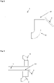
- the screen plate 1 comprises a feed area 2 in which the polysilicon is fed.
- the polysilicon can, for example, be conveyed to the screening plant by means of a conveyor trough and delivered to the feed area 2 of the screen plate 1 .
- the screen plate 1 also includes a profiled area 3.
- This profiled area 3 provides grooves or other types of depressions, so that the profiled area 3 has depressions 31 and peaks 32 .
- the fine fraction contained in the polysilicon collects during the movement of the polysilicon on the profiled area 3 in the depressions 31 of the profiled area 3.
- the screen plate 1 comprises— adjoining the profiled area 3 —an area 4 with screen openings 41 .
- the fine fractions of the polysilicon located in the depressions 31 of the profiled area 3 are guided to the screen openings 41 of the area 4 in a targeted manner.
- the peaks 32 of the profiled area 3 preferably also continue in area 4 , so that the entire screen plate 1 is profiled, but has screen openings 41 in area 4 instead of depressions 31 .
- the fines are thus separated off via the sieve openings 41 of the sieve plate 1 .
- the separated fines can be received, for example, by a collecting container arranged below the sieve openings 41 of the sieve plate 1 .
- the screen openings 41 widen in the conveying direction by an opening angle a1.
- the screen openings 41 have a further widening 6 at the end of the area 4 , characterized by an opening angle a2.
- a suction device 8 is fitted below the screen openings 41 , which is positioned in such a way that the suction device 8 is preferably located between the start of the screen openings 41 and the separating plate 7 .
- Another preferred embodiment of the separation according to the invention is the installation of a gas flow 9 above the screen openings 41.
- the bagged polysilicon material supplied by the polysilicon manufacturer also contains smaller fragments and fines.
- the fine material especially with grain sizes smaller than 4 mm, has a negative impact on the drawing process and must therefore be removed before use. Poly break size 2 was used for the test.
- test polysilicon material 10 kg were placed on a conveyor unit.
- the loading of the test polysilicon material is preferably done via a hopper.
- the container to be filled is positioned at the end of the screening section above the first conveyor unit so that the test polysilicon material can be conveyed into the container without any problems.
- the fines separated in advance for the test are used for this test.
- 2 g of separated fine material are added after each 2 kg of test polymer material, so that at the end a total of 10 g of fine material was added for this test.
- a conveyor unit plus a screening section without suction and without gas flow from above was used for this.
- a conveyor unit plus a screening section with suction but without gas flow from above was used for this.
- a conveyor unit plus a screening section with suction and a gas stream from above was used for this.
- a further improvement in the removal rate is possible if two screen sections are used and suction is provided.
- the separating device therefore comprises two screen plates, each comprising a feed area for polysilicon, a profiled area with peaks and valleys, an area adjoining the profiled area with screen openings, and a removal area, with the screen openings in Widen in the direction of the removal area, and a separating plate arranged below the screen openings, which can be moved horizontally and vertically, and a suction device below the screen openings.
- the removal area of the first screen plate connects to the feed area of the second screen plate, ie polysilicon that was not separated in the first screen section is fed to the second screen section. In both screen sections, suction is provided below the screen openings.
Landscapes
- Engineering & Computer Science (AREA)
- Mechanical Engineering (AREA)
- Silicon Compounds (AREA)
- Combined Means For Separation Of Solids (AREA)
Claims (10)
- Appareil de séparation pour le polysilicium avec au moins une plaque de tamisage (1), comprenant une zone d'alimentation (2) pour le polysilicium, une zone profilée (3) avec des crêtes (32) et des creux (31), une zone (4) adjacente à la zone profilée (3) et présentant des ouvertures de tamisage (41), et une zone de prélèvement (5), les ouvertures de tamisage (41) s'élargissant en direction de la zone de prélèvement (5), caractérisé en ce qu'une plaque de séparation (7) est disposée sous les ouvertures de tamisage, laquelle plaque de séparation (7) peut être déplacée horizontalement afin de régler la position de la zone profilée (3). plaque de séparation dans la direction de la zone d'enlèvement, et qui peut être déplacée verticalement pour faire varier la distance aux ouvertures du tamis.
- Appareil de séparation de la revendication 1, dans lequel un angle d'ouverture de l'élargissement des ouvertures de tamis (41) est supérieur ou égal à 1° et inférieur ou égal à 20°.
- Appareil de séparation selon la revendication 2, dans lequel un angle d'ouverture de l'élargissement des ouvertures du tamis (41) est supérieur ou égal à 5° et inférieur ou égal à 15°.
- Appareil de séparation selon l'une quelconque des revendications 1 à 3, dans lequel lesdites ouvertures de tamisage sont (41) ont une longueur de 5 mm à 50 mm.
- Appareil de séparation selon la revendication 4, dans lequel les ouvertures du tamis (41) ont une longueur de 20 mm à 40 mm.
- Appareil de séparation selon l'une quelconque des revendications 1 à 5, dans lequel les ouvertures du tamis (41) s'élargissent une deuxième fois en direction de la zone de prélèvement après un premier élargissement, dans lequel un angle d'ouverture de ce deuxième élargissement est de 40 à 150°.
- Appareil de séparation selon la revendication 6, dans lequel un angle d'ouverture de la seconde expansion est de 60 à 120°.
- Appareil de séparation selon l'une quelconque des revendications 1 à 7, comprenant un dispositif d'aspiration (8) sous les ouvertures du tamis (41).
- Appareil de séparation selon l'une quelconque des revendications 1 à 8, comprenant des moyens pour diriger un courant gazeux (9) depuis le haut sur les ouvertures du tamis (41).
- Procédé dans lequel du polysilicium est appliqué sur la plaque de tamisage (1) d'un appareil de séparation selon l'une quelconque des revendications 1 à 9, qui est mise en vibration de telle sorte que le polysilicium soit amené à se déplacer dans la direction de l'axe de rotation. une zone d'enlèvement (5), dans laquelle du polysilicium en petites particules s'accumule dans les creux (31) de la plaque de tamisage (1) et tombe à travers les ouvertures de tamisage (41) de la plaque de tamisage (1) via la plaque de séparation (7) dans un récipient collecteur et est ainsi séparé du polysilicium d'alimentation, le polysilicium d'alimentation étant ensuite traité sans le polysilicium en petites particules séparé.
Applications Claiming Priority (2)
| Application Number | Priority Date | Filing Date | Title |
|---|---|---|---|
| DE102016225248.8A DE102016225248A1 (de) | 2016-12-16 | 2016-12-16 | Abscheidevorrichtung für Polysilicium |
| PCT/EP2017/069199 WO2018108334A1 (fr) | 2016-12-16 | 2017-07-28 | Dispositif de séparation pour du polysilicium |
Publications (2)
| Publication Number | Publication Date |
|---|---|
| EP3554723A1 EP3554723A1 (fr) | 2019-10-23 |
| EP3554723B1 true EP3554723B1 (fr) | 2022-11-30 |
Family
ID=59501437
Family Applications (1)
| Application Number | Title | Priority Date | Filing Date |
|---|---|---|---|
| EP17746082.1A Active EP3554723B1 (fr) | 2016-12-16 | 2017-07-28 | Dispositif de séparation pour du polysilicium |
Country Status (9)
| Country | Link |
|---|---|
| US (1) | US11154908B2 (fr) |
| EP (1) | EP3554723B1 (fr) |
| JP (1) | JP7005627B2 (fr) |
| KR (1) | KR102330224B1 (fr) |
| CN (1) | CN110072638B (fr) |
| DE (1) | DE102016225248A1 (fr) |
| FI (1) | FI3554723T3 (fr) |
| TW (1) | TWI660793B (fr) |
| WO (1) | WO2018108334A1 (fr) |
Cited By (1)
| Publication number | Priority date | Publication date | Assignee | Title |
|---|---|---|---|---|
| US12318814B2 (en) | 2023-02-06 | 2025-06-03 | Alztec GmbH | Apparatus and method for flexible classification of polyand/ or monocrystalline silicon |
Families Citing this family (3)
| Publication number | Priority date | Publication date | Assignee | Title |
|---|---|---|---|---|
| KR102800362B1 (ko) * | 2020-08-24 | 2025-04-23 | 와커 헤미 아게 | 벌크 재료 분류를 위한 분리 장치용 스크린 플레이트 |
| US20230392784A1 (en) * | 2020-11-02 | 2023-12-07 | E.On Energiinfrastruktur Ab | Device and method for sorting a particulate stream |
| CN117430119B (zh) * | 2023-12-20 | 2024-02-20 | 四川优赛思智能科技有限公司 | 一种具备自动堵眼功能的工业硅冶炼系统 |
Citations (9)
| Publication number | Priority date | Publication date | Assignee | Title |
|---|---|---|---|---|
| DE826211C (de) * | 1950-06-13 | 1951-12-27 | Dr Albert Remien | Vorrichtung zum Sortieren von Obst u. dgl. |
| EP0139783A1 (fr) * | 1983-11-01 | 1985-05-08 | Ventilatorenfabrik Oelde Gmbh | Appareil pour le traitement de rebuts, déchets ou analogues |
| DE4307138A1 (de) * | 1993-03-06 | 1994-09-08 | Seichter Gmbh | Fördereinrichtung für Schüttgut |
| WO1997026495A2 (fr) * | 1996-01-18 | 1997-07-24 | Siemens Aktiengesellschaft | Dispositif de dechargement |
| US5819951A (en) * | 1996-10-29 | 1998-10-13 | A.S.T. Advanced Screening Technologies Ltd. | Separator plate for the screening of a particulate material and a sorting apparatus comprising same |
| DE19822996C1 (de) * | 1998-05-22 | 1999-04-22 | Siemens Ag | Abscheidevorrichtung für langgestreckte Feststoffteile |
| EP0982081A1 (fr) * | 1998-08-27 | 2000-03-01 | Wacker-Chemie GmbH | Classification pneumatique de polysilicium |
| EP1043249A1 (fr) * | 1999-04-01 | 2000-10-11 | Wacker-Chemie GmbH | Convoyeur vibrant et procédé pour le transport de silicium en vrac |
| US20150090178A1 (en) * | 2002-02-20 | 2015-04-02 | Arvid Neil Arvidson | Flowable Chips and Methods for the Preparation and Use of Same, and Apparatus for Use in the Methods |
Family Cites Families (13)
| Publication number | Priority date | Publication date | Assignee | Title |
|---|---|---|---|---|
| US2074515A (en) * | 1934-08-11 | 1937-03-23 | Valdis M Pyatt | Separator |
| WO1990009246A1 (fr) * | 1989-02-15 | 1990-08-23 | Resource Trend Pty. Ltd. | Concentrateur pneumatique |
| JPH05168450A (ja) | 1991-12-24 | 1993-07-02 | Mitsuwa:Kk | 枝豆選別機 |
| AUPO638997A0 (en) * | 1997-04-23 | 1997-05-22 | Unisearch Limited | Metal contact scheme using selective silicon growth |
| JP2002011408A (ja) | 2000-06-30 | 2002-01-15 | Sumitomo Heavy Ind Ltd | 振動ふるい装置 |
| US6889846B2 (en) * | 2002-03-15 | 2005-05-10 | Johnson Crushers International | Hybrid screen |
| DE102006035081A1 (de) | 2006-07-28 | 2008-01-31 | Wacker Chemie Ag | Verfahren und Vorrichtung zur Herstellung von klassiertem polykristallinen Siliciumbruch in hoher Reinheit |
| KR100882556B1 (ko) * | 2007-06-21 | 2009-02-17 | 주식회사 블루웨일스크린 | 폐수처리용 스크린장치의 스크린바 고정구조 |
| CN202799718U (zh) * | 2012-01-07 | 2013-03-20 | 阿不都克友木·哈地尔 | 一种脱粒清选机 |
| CN104944069A (zh) * | 2014-03-24 | 2015-09-30 | 湖北国煤煤矿机械有限公司 | 一种可调节的筛选中部槽 |
| DE102015206849A1 (de) | 2015-04-16 | 2016-10-20 | Wacker Chemie Ag | Vorrichtung und Verfahren zur Klassierung und Entstaubung von Polysiliciumgranulat |
| DE102015211351A1 (de) | 2015-06-19 | 2016-12-22 | Siltronic Ag | Siebplatte für Siebanlagen zum mechanischen Klassieren von Polysilicium |
| CN205161144U (zh) * | 2015-12-02 | 2016-04-20 | 蒋和忠 | 一种设有链式振动分离筛装置的收割机 |
-
2016
- 2016-12-16 DE DE102016225248.8A patent/DE102016225248A1/de not_active Withdrawn
-
2017
- 2017-07-28 KR KR1020197020447A patent/KR102330224B1/ko active Active
- 2017-07-28 US US16/470,006 patent/US11154908B2/en active Active
- 2017-07-28 WO PCT/EP2017/069199 patent/WO2018108334A1/fr not_active Ceased
- 2017-07-28 JP JP2019531776A patent/JP7005627B2/ja active Active
- 2017-07-28 FI FIEP17746082.1T patent/FI3554723T3/fi active
- 2017-07-28 EP EP17746082.1A patent/EP3554723B1/fr active Active
- 2017-07-28 CN CN201780077025.3A patent/CN110072638B/zh active Active
- 2017-12-12 TW TW106143595A patent/TWI660793B/zh active
Patent Citations (9)
| Publication number | Priority date | Publication date | Assignee | Title |
|---|---|---|---|---|
| DE826211C (de) * | 1950-06-13 | 1951-12-27 | Dr Albert Remien | Vorrichtung zum Sortieren von Obst u. dgl. |
| EP0139783A1 (fr) * | 1983-11-01 | 1985-05-08 | Ventilatorenfabrik Oelde Gmbh | Appareil pour le traitement de rebuts, déchets ou analogues |
| DE4307138A1 (de) * | 1993-03-06 | 1994-09-08 | Seichter Gmbh | Fördereinrichtung für Schüttgut |
| WO1997026495A2 (fr) * | 1996-01-18 | 1997-07-24 | Siemens Aktiengesellschaft | Dispositif de dechargement |
| US5819951A (en) * | 1996-10-29 | 1998-10-13 | A.S.T. Advanced Screening Technologies Ltd. | Separator plate for the screening of a particulate material and a sorting apparatus comprising same |
| DE19822996C1 (de) * | 1998-05-22 | 1999-04-22 | Siemens Ag | Abscheidevorrichtung für langgestreckte Feststoffteile |
| EP0982081A1 (fr) * | 1998-08-27 | 2000-03-01 | Wacker-Chemie GmbH | Classification pneumatique de polysilicium |
| EP1043249A1 (fr) * | 1999-04-01 | 2000-10-11 | Wacker-Chemie GmbH | Convoyeur vibrant et procédé pour le transport de silicium en vrac |
| US20150090178A1 (en) * | 2002-02-20 | 2015-04-02 | Arvid Neil Arvidson | Flowable Chips and Methods for the Preparation and Use of Same, and Apparatus for Use in the Methods |
Cited By (1)
| Publication number | Priority date | Publication date | Assignee | Title |
|---|---|---|---|---|
| US12318814B2 (en) | 2023-02-06 | 2025-06-03 | Alztec GmbH | Apparatus and method for flexible classification of polyand/ or monocrystalline silicon |
Also Published As
| Publication number | Publication date |
|---|---|
| TWI660793B (zh) | 2019-06-01 |
| FI3554723T3 (fi) | 2023-03-21 |
| DE102016225248A1 (de) | 2018-06-21 |
| US11154908B2 (en) | 2021-10-26 |
| TW201838726A (zh) | 2018-11-01 |
| JP7005627B2 (ja) | 2022-01-21 |
| EP3554723A1 (fr) | 2019-10-23 |
| KR102330224B1 (ko) | 2021-11-22 |
| JP2020513313A (ja) | 2020-05-14 |
| CN110072638B (zh) | 2022-08-26 |
| CN110072638A (zh) | 2019-07-30 |
| WO2018108334A1 (fr) | 2018-06-21 |
| KR20190097152A (ko) | 2019-08-20 |
| US20200086348A1 (en) | 2020-03-19 |
Similar Documents
| Publication | Publication Date | Title |
|---|---|---|
| EP3310499B1 (fr) | Procédé pour le calibrage mécanique du polysilicium | |
| EP2055395B1 (fr) | Procédé et dispositif destinés au criblage de particules | |
| EP0982081B1 (fr) | Classification pneumatique de polysilicium | |
| EP3554723B1 (fr) | Dispositif de séparation pour du polysilicium | |
| EP0876851B1 (fr) | Dispositif de classement optoélectronique | |
| EP0332929B2 (fr) | Procédé et dispositif pour la granulation dans un lit fluidisé | |
| EP3043929B1 (fr) | Classification de silicium polycristallin | |
| EP2666750B1 (fr) | Silicium polycristallin | |
| DE112010005677B4 (de) | Vorrichtung zur pneumatischen Vakuumsichtung von Schüttgut | |
| EP2730510B1 (fr) | Méthode pour emballer du silicium polycristallin | |
| EP0636322B1 (fr) | Dispositif de transport pour la formation d'une couche uniforme | |
| WO2016165959A1 (fr) | Dispositif et procédé de criblage et de dépoussiérage de granulat de polysilicium | |
| DE68911533T2 (de) | Windsichter für produktteilchen. | |
| EP3115151A1 (fr) | Recuperation d'agent abrasif a partir d'installations de decoupe au jet abrasif | |
| DE102005062090B4 (de) | Sichtvorrichtung und Verfahren zum Trennen von schweren und leichten Partikeln von Tabakmaterial | |
| DE102008058998B4 (de) | Verfahren zur Sichtung bzw. Klassifizierung von geschnittenem, pflanzlichen Schüttgut, insbesondere Tabak, sowie Vorrichtung zur Durchführung des Verfahrens | |
| EP4200085B1 (fr) | Plaque de tamis de dispositif de séparation pour classer des matériaux en vrac | |
| EP3403731A1 (fr) | Dispositif d'homogénéisation et de séparation de mélanges de particules | |
| DE3804190A1 (de) | Vorrichtung zum klassieren eines stroms von partikeln und verwendung der vorrichtung | |
| DE872304C (de) | Verfahren und Vorrichtung zum Sichten von pulverfoermigem Material | |
| DE19915122A1 (de) | Steigrohrsichter für die Wirbelschichtgranulation | |
| DE1507735B1 (de) | Vorrichtung zum Querstromsichten von koernigem Gut bei Trenngrenzen unterhalb 1 mm und Verfahren zu deren Betrieb |
Legal Events
| Date | Code | Title | Description |
|---|---|---|---|
| STAA | Information on the status of an ep patent application or granted ep patent |
Free format text: STATUS: UNKNOWN |
|
| STAA | Information on the status of an ep patent application or granted ep patent |
Free format text: STATUS: THE INTERNATIONAL PUBLICATION HAS BEEN MADE |
|
| PUAI | Public reference made under article 153(3) epc to a published international application that has entered the european phase |
Free format text: ORIGINAL CODE: 0009012 |
|
| STAA | Information on the status of an ep patent application or granted ep patent |
Free format text: STATUS: REQUEST FOR EXAMINATION WAS MADE |
|
| 17P | Request for examination filed |
Effective date: 20190603 |
|
| AK | Designated contracting states |
Kind code of ref document: A1 Designated state(s): AL AT BE BG CH CY CZ DE DK EE ES FI FR GB GR HR HU IE IS IT LI LT LU LV MC MK MT NL NO PL PT RO RS SE SI SK SM TR |
|
| AX | Request for extension of the european patent |
Extension state: BA ME |
|
| DAV | Request for validation of the european patent (deleted) | ||
| DAX | Request for extension of the european patent (deleted) | ||
| STAA | Information on the status of an ep patent application or granted ep patent |
Free format text: STATUS: EXAMINATION IS IN PROGRESS |
|
| 17Q | First examination report despatched |
Effective date: 20200715 |
|
| RAP1 | Party data changed (applicant data changed or rights of an application transferred) |
Owner name: SILTRONIC AG |
|
| GRAP | Despatch of communication of intention to grant a patent |
Free format text: ORIGINAL CODE: EPIDOSNIGR1 |
|
| STAA | Information on the status of an ep patent application or granted ep patent |
Free format text: STATUS: GRANT OF PATENT IS INTENDED |
|
| INTG | Intention to grant announced |
Effective date: 20220623 |
|
| GRAS | Grant fee paid |
Free format text: ORIGINAL CODE: EPIDOSNIGR3 |
|
| GRAA | (expected) grant |
Free format text: ORIGINAL CODE: 0009210 |
|
| STAA | Information on the status of an ep patent application or granted ep patent |
Free format text: STATUS: THE PATENT HAS BEEN GRANTED |
|
| AK | Designated contracting states |
Kind code of ref document: B1 Designated state(s): AL AT BE BG CH CY CZ DE DK EE ES FI FR GB GR HR HU IE IS IT LI LT LU LV MC MK MT NL NO PL PT RO RS SE SI SK SM TR |
|
| REG | Reference to a national code |
Ref country code: CH Ref legal event code: EP Ref country code: GB Ref legal event code: FG4D Free format text: NOT ENGLISH |
|
| REG | Reference to a national code |
Ref country code: AT Ref legal event code: REF Ref document number: 1534277 Country of ref document: AT Kind code of ref document: T Effective date: 20221215 |
|
| REG | Reference to a national code |
Ref country code: IE Ref legal event code: FG4D Free format text: LANGUAGE OF EP DOCUMENT: GERMAN |
|
| REG | Reference to a national code |
Ref country code: DE Ref legal event code: R096 Ref document number: 502017014160 Country of ref document: DE |
|
| REG | Reference to a national code |
Ref country code: LT Ref legal event code: MG9D |
|
| REG | Reference to a national code |
Ref country code: NL Ref legal event code: MP Effective date: 20221130 |
|
| PG25 | Lapsed in a contracting state [announced via postgrant information from national office to epo] |
Ref country code: SE Free format text: LAPSE BECAUSE OF FAILURE TO SUBMIT A TRANSLATION OF THE DESCRIPTION OR TO PAY THE FEE WITHIN THE PRESCRIBED TIME-LIMIT Effective date: 20221130 Ref country code: PT Free format text: LAPSE BECAUSE OF FAILURE TO SUBMIT A TRANSLATION OF THE DESCRIPTION OR TO PAY THE FEE WITHIN THE PRESCRIBED TIME-LIMIT Effective date: 20230331 Ref country code: NO Free format text: LAPSE BECAUSE OF FAILURE TO SUBMIT A TRANSLATION OF THE DESCRIPTION OR TO PAY THE FEE WITHIN THE PRESCRIBED TIME-LIMIT Effective date: 20230228 Ref country code: LT Free format text: LAPSE BECAUSE OF FAILURE TO SUBMIT A TRANSLATION OF THE DESCRIPTION OR TO PAY THE FEE WITHIN THE PRESCRIBED TIME-LIMIT Effective date: 20221130 Ref country code: ES Free format text: LAPSE BECAUSE OF FAILURE TO SUBMIT A TRANSLATION OF THE DESCRIPTION OR TO PAY THE FEE WITHIN THE PRESCRIBED TIME-LIMIT Effective date: 20221130 |
|
| PG25 | Lapsed in a contracting state [announced via postgrant information from national office to epo] |
Ref country code: RS Free format text: LAPSE BECAUSE OF FAILURE TO SUBMIT A TRANSLATION OF THE DESCRIPTION OR TO PAY THE FEE WITHIN THE PRESCRIBED TIME-LIMIT Effective date: 20221130 Ref country code: PL Free format text: LAPSE BECAUSE OF FAILURE TO SUBMIT A TRANSLATION OF THE DESCRIPTION OR TO PAY THE FEE WITHIN THE PRESCRIBED TIME-LIMIT Effective date: 20221130 Ref country code: LV Free format text: LAPSE BECAUSE OF FAILURE TO SUBMIT A TRANSLATION OF THE DESCRIPTION OR TO PAY THE FEE WITHIN THE PRESCRIBED TIME-LIMIT Effective date: 20221130 Ref country code: IS Free format text: LAPSE BECAUSE OF FAILURE TO SUBMIT A TRANSLATION OF THE DESCRIPTION OR TO PAY THE FEE WITHIN THE PRESCRIBED TIME-LIMIT Effective date: 20230330 Ref country code: HR Free format text: LAPSE BECAUSE OF FAILURE TO SUBMIT A TRANSLATION OF THE DESCRIPTION OR TO PAY THE FEE WITHIN THE PRESCRIBED TIME-LIMIT Effective date: 20221130 Ref country code: GR Free format text: LAPSE BECAUSE OF FAILURE TO SUBMIT A TRANSLATION OF THE DESCRIPTION OR TO PAY THE FEE WITHIN THE PRESCRIBED TIME-LIMIT Effective date: 20230301 |
|
| PG25 | Lapsed in a contracting state [announced via postgrant information from national office to epo] |
Ref country code: NL Free format text: LAPSE BECAUSE OF FAILURE TO SUBMIT A TRANSLATION OF THE DESCRIPTION OR TO PAY THE FEE WITHIN THE PRESCRIBED TIME-LIMIT Effective date: 20221130 |
|
| PG25 | Lapsed in a contracting state [announced via postgrant information from national office to epo] |
Ref country code: SM Free format text: LAPSE BECAUSE OF FAILURE TO SUBMIT A TRANSLATION OF THE DESCRIPTION OR TO PAY THE FEE WITHIN THE PRESCRIBED TIME-LIMIT Effective date: 20221130 Ref country code: RO Free format text: LAPSE BECAUSE OF FAILURE TO SUBMIT A TRANSLATION OF THE DESCRIPTION OR TO PAY THE FEE WITHIN THE PRESCRIBED TIME-LIMIT Effective date: 20221130 Ref country code: EE Free format text: LAPSE BECAUSE OF FAILURE TO SUBMIT A TRANSLATION OF THE DESCRIPTION OR TO PAY THE FEE WITHIN THE PRESCRIBED TIME-LIMIT Effective date: 20221130 Ref country code: DK Free format text: LAPSE BECAUSE OF FAILURE TO SUBMIT A TRANSLATION OF THE DESCRIPTION OR TO PAY THE FEE WITHIN THE PRESCRIBED TIME-LIMIT Effective date: 20221130 Ref country code: CZ Free format text: LAPSE BECAUSE OF FAILURE TO SUBMIT A TRANSLATION OF THE DESCRIPTION OR TO PAY THE FEE WITHIN THE PRESCRIBED TIME-LIMIT Effective date: 20221130 |
|
| PG25 | Lapsed in a contracting state [announced via postgrant information from national office to epo] |
Ref country code: SK Free format text: LAPSE BECAUSE OF FAILURE TO SUBMIT A TRANSLATION OF THE DESCRIPTION OR TO PAY THE FEE WITHIN THE PRESCRIBED TIME-LIMIT Effective date: 20221130 Ref country code: AL Free format text: LAPSE BECAUSE OF FAILURE TO SUBMIT A TRANSLATION OF THE DESCRIPTION OR TO PAY THE FEE WITHIN THE PRESCRIBED TIME-LIMIT Effective date: 20221130 |
|
| REG | Reference to a national code |
Ref country code: DE Ref legal event code: R097 Ref document number: 502017014160 Country of ref document: DE |
|
| PLBE | No opposition filed within time limit |
Free format text: ORIGINAL CODE: 0009261 |
|
| STAA | Information on the status of an ep patent application or granted ep patent |
Free format text: STATUS: NO OPPOSITION FILED WITHIN TIME LIMIT |
|
| 26N | No opposition filed |
Effective date: 20230831 |
|
| PG25 | Lapsed in a contracting state [announced via postgrant information from national office to epo] |
Ref country code: SI Free format text: LAPSE BECAUSE OF FAILURE TO SUBMIT A TRANSLATION OF THE DESCRIPTION OR TO PAY THE FEE WITHIN THE PRESCRIBED TIME-LIMIT Effective date: 20221130 |
|
| PG25 | Lapsed in a contracting state [announced via postgrant information from national office to epo] |
Ref country code: MC Free format text: LAPSE BECAUSE OF FAILURE TO SUBMIT A TRANSLATION OF THE DESCRIPTION OR TO PAY THE FEE WITHIN THE PRESCRIBED TIME-LIMIT Effective date: 20221130 |
|
| PG25 | Lapsed in a contracting state [announced via postgrant information from national office to epo] |
Ref country code: MC Free format text: LAPSE BECAUSE OF FAILURE TO SUBMIT A TRANSLATION OF THE DESCRIPTION OR TO PAY THE FEE WITHIN THE PRESCRIBED TIME-LIMIT Effective date: 20221130 |
|
| REG | Reference to a national code |
Ref country code: CH Ref legal event code: PL |
|
| REG | Reference to a national code |
Ref country code: BE Ref legal event code: MM Effective date: 20230731 |
|
| PG25 | Lapsed in a contracting state [announced via postgrant information from national office to epo] |
Ref country code: LU Free format text: LAPSE BECAUSE OF NON-PAYMENT OF DUE FEES Effective date: 20230728 |
|
| GBPC | Gb: european patent ceased through non-payment of renewal fee |
Effective date: 20230728 |
|
| PG25 | Lapsed in a contracting state [announced via postgrant information from national office to epo] |
Ref country code: LU Free format text: LAPSE BECAUSE OF NON-PAYMENT OF DUE FEES Effective date: 20230728 |
|
| REG | Reference to a national code |
Ref country code: IE Ref legal event code: MM4A |
|
| PG25 | Lapsed in a contracting state [announced via postgrant information from national office to epo] |
Ref country code: GB Free format text: LAPSE BECAUSE OF NON-PAYMENT OF DUE FEES Effective date: 20230728 Ref country code: CH Free format text: LAPSE BECAUSE OF NON-PAYMENT OF DUE FEES Effective date: 20230731 |
|
| PG25 | Lapsed in a contracting state [announced via postgrant information from national office to epo] |
Ref country code: FR Free format text: LAPSE BECAUSE OF NON-PAYMENT OF DUE FEES Effective date: 20230731 Ref country code: BE Free format text: LAPSE BECAUSE OF NON-PAYMENT OF DUE FEES Effective date: 20230731 |
|
| PG25 | Lapsed in a contracting state [announced via postgrant information from national office to epo] |
Ref country code: IE Free format text: LAPSE BECAUSE OF NON-PAYMENT OF DUE FEES Effective date: 20230728 |
|
| PG25 | Lapsed in a contracting state [announced via postgrant information from national office to epo] |
Ref country code: IE Free format text: LAPSE BECAUSE OF NON-PAYMENT OF DUE FEES Effective date: 20230728 |
|
| REG | Reference to a national code |
Ref country code: AT Ref legal event code: MM01 Ref document number: 1534277 Country of ref document: AT Kind code of ref document: T Effective date: 20230728 |
|
| PG25 | Lapsed in a contracting state [announced via postgrant information from national office to epo] |
Ref country code: AT Free format text: LAPSE BECAUSE OF NON-PAYMENT OF DUE FEES Effective date: 20230728 |
|
| PG25 | Lapsed in a contracting state [announced via postgrant information from national office to epo] |
Ref country code: AT Free format text: LAPSE BECAUSE OF NON-PAYMENT OF DUE FEES Effective date: 20230728 |
|
| PG25 | Lapsed in a contracting state [announced via postgrant information from national office to epo] |
Ref country code: BG Free format text: LAPSE BECAUSE OF FAILURE TO SUBMIT A TRANSLATION OF THE DESCRIPTION OR TO PAY THE FEE WITHIN THE PRESCRIBED TIME-LIMIT Effective date: 20221130 |
|
| PG25 | Lapsed in a contracting state [announced via postgrant information from national office to epo] |
Ref country code: BG Free format text: LAPSE BECAUSE OF FAILURE TO SUBMIT A TRANSLATION OF THE DESCRIPTION OR TO PAY THE FEE WITHIN THE PRESCRIBED TIME-LIMIT Effective date: 20221130 |
|
| PG25 | Lapsed in a contracting state [announced via postgrant information from national office to epo] |
Ref country code: CY Free format text: LAPSE BECAUSE OF FAILURE TO SUBMIT A TRANSLATION OF THE DESCRIPTION OR TO PAY THE FEE WITHIN THE PRESCRIBED TIME-LIMIT; INVALID AB INITIO Effective date: 20170728 |
|
| PG25 | Lapsed in a contracting state [announced via postgrant information from national office to epo] |
Ref country code: HU Free format text: LAPSE BECAUSE OF FAILURE TO SUBMIT A TRANSLATION OF THE DESCRIPTION OR TO PAY THE FEE WITHIN THE PRESCRIBED TIME-LIMIT; INVALID AB INITIO Effective date: 20170728 |
|
| PGFP | Annual fee paid to national office [announced via postgrant information from national office to epo] |
Ref country code: FI Payment date: 20250725 Year of fee payment: 9 |
|
| PGFP | Annual fee paid to national office [announced via postgrant information from national office to epo] |
Ref country code: DE Payment date: 20250722 Year of fee payment: 9 |
|
| PGFP | Annual fee paid to national office [announced via postgrant information from national office to epo] |
Ref country code: IT Payment date: 20250724 Year of fee payment: 9 |
|
| PG25 | Lapsed in a contracting state [announced via postgrant information from national office to epo] |
Ref country code: TR Free format text: LAPSE BECAUSE OF FAILURE TO SUBMIT A TRANSLATION OF THE DESCRIPTION OR TO PAY THE FEE WITHIN THE PRESCRIBED TIME-LIMIT Effective date: 20221130 |