EP3554723B1 - Separating device for polycrystalline silicon - Google Patents
Separating device for polycrystalline silicon Download PDFInfo
- Publication number
- EP3554723B1 EP3554723B1 EP17746082.1A EP17746082A EP3554723B1 EP 3554723 B1 EP3554723 B1 EP 3554723B1 EP 17746082 A EP17746082 A EP 17746082A EP 3554723 B1 EP3554723 B1 EP 3554723B1
- Authority
- EP
- European Patent Office
- Prior art keywords
- screen
- polysilicon
- area
- plate
- openings
- Prior art date
- Legal status (The legal status is an assumption and is not a legal conclusion. Google has not performed a legal analysis and makes no representation as to the accuracy of the status listed.)
- Active
Links
Images

Classifications
-
- B—PERFORMING OPERATIONS; TRANSPORTING
- B07—SEPARATING SOLIDS FROM SOLIDS; SORTING
- B07B—SEPARATING SOLIDS FROM SOLIDS BY SIEVING, SCREENING, SIFTING OR BY USING GAS CURRENTS; SEPARATING BY OTHER DRY METHODS APPLICABLE TO BULK MATERIAL, e.g. LOOSE ARTICLES FIT TO BE HANDLED LIKE BULK MATERIAL
- B07B13/00—Grading or sorting solid materials by dry methods, not otherwise provided for; Sorting articles otherwise than by indirectly controlled devices
- B07B13/04—Grading or sorting solid materials by dry methods, not otherwise provided for; Sorting articles otherwise than by indirectly controlled devices according to size
- B07B13/07—Apparatus in which aggregates or articles are moved along or past openings which increase in size in the direction of movement
-
- B—PERFORMING OPERATIONS; TRANSPORTING
- B07—SEPARATING SOLIDS FROM SOLIDS; SORTING
- B07B—SEPARATING SOLIDS FROM SOLIDS BY SIEVING, SCREENING, SIFTING OR BY USING GAS CURRENTS; SEPARATING BY OTHER DRY METHODS APPLICABLE TO BULK MATERIAL, e.g. LOOSE ARTICLES FIT TO BE HANDLED LIKE BULK MATERIAL
- B07B1/00—Sieving, screening, sifting, or sorting solid materials using networks, gratings, grids, or the like
- B07B1/46—Constructional details of screens in general; Cleaning or heating of screens
- B07B1/4609—Constructional details of screens in general; Cleaning or heating of screens constructional details of screening surfaces or meshes
- B07B1/4654—Corrugated Screening surfaces
-
- B—PERFORMING OPERATIONS; TRANSPORTING
- B07—SEPARATING SOLIDS FROM SOLIDS; SORTING
- B07B—SEPARATING SOLIDS FROM SOLIDS BY SIEVING, SCREENING, SIFTING OR BY USING GAS CURRENTS; SEPARATING BY OTHER DRY METHODS APPLICABLE TO BULK MATERIAL, e.g. LOOSE ARTICLES FIT TO BE HANDLED LIKE BULK MATERIAL
- B07B13/00—Grading or sorting solid materials by dry methods, not otherwise provided for; Sorting articles otherwise than by indirectly controlled devices
- B07B13/14—Details or accessories
- B07B13/16—Feed or discharge arrangements
-
- B—PERFORMING OPERATIONS; TRANSPORTING
- B07—SEPARATING SOLIDS FROM SOLIDS; SORTING
- B07B—SEPARATING SOLIDS FROM SOLIDS BY SIEVING, SCREENING, SIFTING OR BY USING GAS CURRENTS; SEPARATING BY OTHER DRY METHODS APPLICABLE TO BULK MATERIAL, e.g. LOOSE ARTICLES FIT TO BE HANDLED LIKE BULK MATERIAL
- B07B4/00—Separating solids from solids by subjecting their mixture to gas currents
- B07B4/08—Separating solids from solids by subjecting their mixture to gas currents while the mixtures are supported by sieves, screens, or like mechanical elements
Definitions
- the subject matter of the invention is a deposition device for polysilicon.
- Polycrystalline silicon (polysilicon for short) is used as a starting material for the production of monocrystalline silicon for semiconductors using the Czochralski (CZ) or zone melting (FZ) process, as well as for the production of monocrystalline or multicrystalline silicon using various drawing and casting processes Production of solar cells for photovoltaics.
- CZ Czochralski
- FZ zone melting
- Polycrystalline silicon is usually manufactured using the Siemens process. For most applications, the polycrystalline silicon rods produced in this way are broken up into small fragments, which are then usually classified according to size. Usually, screening machines are used to sort or classify polycrystalline silicon into different size classes after comminution.
- polycrystalline silicon granules are produced in a fluidized bed reactor. After it has been produced, the polysilicon granules are usually divided into two or more fractions or classes (classification) by means of a screening plant.
- a screening machine is generally a machine for screening, i.e. the separation (separation) of solid mixtures according to grain sizes.
- the screening machines are usually driven electromagnetically or by unbalance motors or gears.
- the movement of the screen lining serves to transport the feed material further in the longitudinal direction of the screen and to allow the fine fraction to pass through the screen openings.
- throw screens experience not only horizontal but also vertical screen acceleration.
- DE 43 07 138 A1 discloses a separating device with at least one screen plate, comprising a feed area for polysilicon, a profiled V-shaped area and a sink, an area adjoining the profiled area with screen openings, and a removal area, with the screen openings widening in the direction of the removal area, and a Separation plate arranged below the screen openings.
- EP 0 982 081 A1 discloses a device for classifying which has at least one blowing device (5) and at least one deflection device (3).
- WO 97/26495 A2 discloses a conveying device made of a profiled separating base, on which a bar rake is formed at the end facing away from the opening of the residue conveying chute.
- the bar screen covers a fine debris discharge port and terminates at a coarse debris outlet.
- EP 0 139 783 A1 discloses a device for processing scrap, waste or the like, e.g. non-ferrous scrap, by dividing it into at least two components, consisting of at least one sorting plate arranged inclined to the horizontal and an input device arranged above the sorting plate, from which the material to be processed falls freely onto the Sorting plate can be brought, wherein the sorting plate can be moved both horizontally and vertically by means of at least one drive unit.
- DE 826 211 C discloses a device for sorting fruit, characterized in that a carrier conveyor belt and a wall made of individual circulating conveying means conveying in the same direction are arranged in the form of a trough and a passage opening of a specific cross-section is provided between every two of these conveying means, with the conveying means forming the conveying wall having a higher speed as the conveyor belt circulate
- Out of DE 198 22 996 C1 is a separating device for elongate solid parts, which has a vibrating base with a number of longitudinal grooves extending in the conveying direction, which are followed by screen openings for separating the elongate solid parts, the groove depth of the longitudinal grooves decreasing in the conveying direction.
- the screen openings In order to avoid blockages and to ensure that the flow of solids is as liquid as possible, one embodiment provides for the screen openings to widen in the conveying direction. On jammed in the screen opening solid parts, a force is exerted in the conveying direction by the following solid. The jammed solid part can be moved in the conveying direction and then falls through the widening screen opening.
- U.S. 2015/090178 A1 discloses a separating device for polysilicon with at least one screen plate, comprising a feed area for polysilicon, a profiled area with peaks and valleys, an area adjoining the profiled area with screen openings, and a removal area, with the screen openings widening in the direction of the removal area, and a Separating plate arranged below the screen openings, which is horizontally displaceable.
- a separating device for polysilicon with at least one screen plate comprising a feed area for polysilicon, a profiled area with peaks and valleys, an area adjoining the profiled area with screen openings, and a removal area, with the screen openings in the direction of the removal area, characterized in that below the screen openings there is a separating plate which can be displaced horizontally in order to vary the position of the separating plate in the direction of the removal area and which can be displaced vertically in order to vary the distance to the screen openings.
- the screen plate according to the invention provides a separating plate which is arranged below the screen openings or the area with screen openings.
- the effective size of the screen openings can be varied by shifting the separating plate in the conveying direction.
- the separating plate can be arranged in such a way that polysilicon with a size of less than or equal to 4 mm falls through the screen opening and is separated from the remaining polysilicon via the separating plate.
- the separating plate may be inclined from the vertical such that the separated polysilicon is received in a catch bin, while larger polysilicon, although also falling through the screen openings, is received in another catch bin located downstream of the separating plate.
- two fractions can also be separated from the polysilicon fed in by the sieve plate in conjunction with the separating plate.
- the partition plate can therefore fulfill very different functions.
- the object is also achieved by a method in which polysilicon is placed on the screen plate of a separating device according to the invention, which is made to vibrate in such a way that the polysilicon moves in the direction of the removal area, with small-sized polysilicon collecting in the depressions of the screen plate and through the screen openings of the screen plate falls over the separating plate into a collection container and is thereby separated from the polysilicon that has been fed in, with the polysilicon that has been fed in being processed further without the separated, small-sized polysilicon.
- the position and height of the separator plate is chosen depending on how much the polysilicon has been vibrated.
- the separating plate is preferably at a distance from the screen section of 5 mm to 20 mm, a distance of 1 mm to 5 mm being particularly preferred.
- Small-scale polysilicon is to be understood as meaning a subset of the quantity of polysilicon that is to be separated off by means of the screening plant.
- the small-scale polysilicon thus corresponds to the fraction to be separated.
- the screen plate includes a feed area where the polysilicon is fed.
- the polysilicon is conveyed to the screening plant by means of a conveyor trough and delivered to the feed area of the screen plate.
- the screen plate also includes a profiled area with ridges or grooves or generally indentations and elevations, so that the profiled area has depressions and peaks.
- the screen plate includes - adjoining the profiled area - an area with screen openings.
- the screen openings are arranged in the conveying direction directly behind the sinks of the profiled area.
- the peaks of the profiled area also continue into the area with screen openings, so that the entire screen plate is profiled, but the screen plate has screen openings instead of depressions at its rear end in the conveying direction.
- the profile of the profiled area can deviate from the profile in the area of the screen openings in terms of cross section and angle. The latter can be advantageous in particular when the screen section or the parts of the screen section that come into contact with the polysilicon are made of plastic.
- the fines or small fragments/particles are separated via the screen openings of the screen plate in connection with the separating plate.
- the separated fines or small fragments/particles are collected by a collection container arranged below the screen openings of the screen plate.
- the removal area is connected to a conveyor trough, via which the larger fragments are removed.
- Another sieve plate can also follow in order to separate another fraction from the polysilicon.
- the invention therefore provides a screen plate that can be used in all types of screening plants, in which the fines or small-sized silicon collects in depressions in the first area of the screen plate and is selectively separated in the last area of the screen plate by widening screen openings.
- the design of the profiled area of the screen plate depends on the fraction to be separated.
- the depth and angle of the depressions in the profiled area must be designed in such a way that the fraction to be separated, e.g. the fine fraction, collects there.
- the invention thus relates to a screening section in which the fine fraction collects in sinks in the first area of the device and is selectively separated in the last area of the device by widening screen openings. Thus, not the entire fraction is fed to the screen slot.
- the separating device essentially consists of a screening section which can be divided into two areas.
- the first area is the entry area. In this area, the fines collect in the sinks and are thus fed to the screen openings (which are located in the second area, at the end of the screening section).
- the separating cut for the separation takes place in the second area of the screening section via the screen openings introduced there, which widen in the conveying direction.
- the desired Si fraction is separated off through these screen openings or the fines. Due to the fact that the screen openings widen in the conveying direction, this system does not tend to clog.
- the screen openings extend as far as the end of the separating device located in the conveying direction.
- the screen openings are therefore designed to be open towards the end. This is an essential feature to ensure that no silicon fragments accumulate in the separator or the screen opening becomes blocked.
- the screen openings preferably have an opening angle of 1 to 20° and particularly preferably 5-15°.
- the screen openings preferably have a length of 5 mm to 50 mm, particularly preferably a length of 20 to 40 mm.
- a further advantageous embodiment provides that the screen openings widen further at the end in the conveying direction.
- the opening angle of this second widening is preferably 40-150°, particularly preferably 60 to 120°.
- the angle of the screen openings can be changed using suitable devices.
- elements made of an elastic material can be used for this purpose. It has been shown that this is advantageous for avoiding clogging.
- a suction device is attached below the screen openings, which is positioned in such a way that the suction device is preferably located between the start of the screen openings and the separating plate.
- the suction is preferably at a distance from the lower sieve plate of 1 mm to 50 mm, a distance of 5 mm to 20 mm is particularly preferred.
- a further preferred embodiment of the separation according to the invention is the installation of a gas stream above the screen openings.
- the gas jet can be soft or hard.
- a soft jet is particularly suitable for supporting the separation of dust.
- a hard jet is particularly suitable for depositing the smaller polysilicon fragments, 0.1mm to 4mm.
- the gas flow can also be designed as a laminar flow.
- Clean room air according to DIN EN ISO 14644-1 (ISO1 to ISO6), clean dry air, nitrogen and argon can be considered as gases.
- the gas flow should preferably be positioned between the start of the screen openings and the separating plate.
- the removal area is connected to a conveyor trough, via which the larger fragments are removed.
- Another sieve plate can also follow in order to separate another fraction from the polysilicon.
- the screen path consists of one or more materials selected from the group consisting of plastic, ceramic, glass, diamond, amorphous carbon, silicon or metal, fused silica lined metal and silicon lined metal
- the screen section is lined or coated with one or more materials selected from the group consisting of plastic, ceramic, glass, diamond, amorphous carbon, and silicon.
- the portions of the screen that come into contact with the polysilicon are lined or coated with one or more materials selected from the group consisting of plastic, ceramic, glass, diamond, amorphous carbon, and silicon.
- the screening section comprises a metallic base body and a coating or lining made from one or more materials selected from the group consisting of plastic, ceramic, glass, diamond, amorphous carbon and silicon.
- the screening section comprises a base body made of plastic and a coating or lining made of one or more materials selected from the group consisting of ceramic, glass, diamond, amorphous carbon and silicon.
- the plastic used in the aforementioned versions is selected from the group consisting of PVC (polyvinyl chloride), PP (polypropylene), PE (polyethylene), PU (polyurethane), PFA (perfluoroalkoxy), PVDF (polyvinylidene fluoride) and PTFE (polytetrafluoroethylene).
- PVC polyvinyl chloride
- PP polypropylene
- PE polyethylene
- PU polyurethane
- PFA perfluoroalkoxy
- PVDF polyvinylidene fluoride
- PTFE polytetrafluoroethylene
- the screening section includes a coating of titanium nitride, titanium carbide, aluminum titanium nitride, DLC (Diamond Like Carbon), silicon carbide, nitride-bonded silicon carbide, or tungsten carbide.
- fraction sizes (BG) 1, 2, 3 can preferably be used via this screening device. Typically, these fractional sizes have the following dimensions. Fraction size 1 3 to 15mm Fraction size 2 10 to 40mm fraction size 3 20 to 60mm
- the individual fragment size classes have small and larger fragments.
- the proportion of larger and smaller fragments can each be up to 5%.
- the screening device is suitable for separating small pieces of polysilicon, which have a diameter of about 0.05 to 2 mm and typically a length of up to 4 mm.
- the separating device comprises a hopper for feeding in the polysilicon material, two conveyor units and two screening sections, with a screening section following each conveyor unit.
- a conveyor unit and a screening section form one unit.
- the first unit is called unit 1 and the second unit is called unit 2.
- the polysilicon delivery rate in kg/min can be set separately for each unit.
- the flow rate of unit 1 is preferably the same as that of unit 2.
- the delivery rate of unit 1 is particularly preferably smaller than the delivery rate of unit 2, because this can result in the polysilicon fragments being isolated on unit 2, with the result that the small polysilicon fragments and the dust can be separated off better.
- the removal area is designed in such a way that the polysilicon material slides into the container provided.
- This extraction area can also be vibrated to ensure that no polysilicon material is left behind.
- the angle of this outlet is preferably 5 to 45° and more preferably 15 to 25°.
- the screen plate 1 comprises a feed area 2 in which the polysilicon is fed.
- the polysilicon can, for example, be conveyed to the screening plant by means of a conveyor trough and delivered to the feed area 2 of the screen plate 1 .
- the screen plate 1 also includes a profiled area 3.
- This profiled area 3 provides grooves or other types of depressions, so that the profiled area 3 has depressions 31 and peaks 32 .
- the fine fraction contained in the polysilicon collects during the movement of the polysilicon on the profiled area 3 in the depressions 31 of the profiled area 3.
- the screen plate 1 comprises— adjoining the profiled area 3 —an area 4 with screen openings 41 .
- the fine fractions of the polysilicon located in the depressions 31 of the profiled area 3 are guided to the screen openings 41 of the area 4 in a targeted manner.
- the peaks 32 of the profiled area 3 preferably also continue in area 4 , so that the entire screen plate 1 is profiled, but has screen openings 41 in area 4 instead of depressions 31 .
- the fines are thus separated off via the sieve openings 41 of the sieve plate 1 .
- the separated fines can be received, for example, by a collecting container arranged below the sieve openings 41 of the sieve plate 1 .
- the screen openings 41 widen in the conveying direction by an opening angle a1.
- the screen openings 41 have a further widening 6 at the end of the area 4 , characterized by an opening angle a2.
- a suction device 8 is fitted below the screen openings 41 , which is positioned in such a way that the suction device 8 is preferably located between the start of the screen openings 41 and the separating plate 7 .
- Another preferred embodiment of the separation according to the invention is the installation of a gas flow 9 above the screen openings 41.
- the bagged polysilicon material supplied by the polysilicon manufacturer also contains smaller fragments and fines.
- the fine material especially with grain sizes smaller than 4 mm, has a negative impact on the drawing process and must therefore be removed before use. Poly break size 2 was used for the test.
- test polysilicon material 10 kg were placed on a conveyor unit.
- the loading of the test polysilicon material is preferably done via a hopper.
- the container to be filled is positioned at the end of the screening section above the first conveyor unit so that the test polysilicon material can be conveyed into the container without any problems.
- the fines separated in advance for the test are used for this test.
- 2 g of separated fine material are added after each 2 kg of test polymer material, so that at the end a total of 10 g of fine material was added for this test.
- a conveyor unit plus a screening section without suction and without gas flow from above was used for this.
- a conveyor unit plus a screening section with suction but without gas flow from above was used for this.
- a conveyor unit plus a screening section with suction and a gas stream from above was used for this.
- a further improvement in the removal rate is possible if two screen sections are used and suction is provided.
- the separating device therefore comprises two screen plates, each comprising a feed area for polysilicon, a profiled area with peaks and valleys, an area adjoining the profiled area with screen openings, and a removal area, with the screen openings in Widen in the direction of the removal area, and a separating plate arranged below the screen openings, which can be moved horizontally and vertically, and a suction device below the screen openings.
- the removal area of the first screen plate connects to the feed area of the second screen plate, ie polysilicon that was not separated in the first screen section is fed to the second screen section. In both screen sections, suction is provided below the screen openings.
Landscapes
- Engineering & Computer Science (AREA)
- Mechanical Engineering (AREA)
- Silicon Compounds (AREA)
- Combined Means For Separation Of Solids (AREA)
Description
Gegenstand der Erfindung ist eine Abscheidevorrichtung für Polysilicium.The subject matter of the invention is a deposition device for polysilicon.
Polykristallines Silicium (kurz: Polysilicium) dient als Ausgangsmaterial zur Herstellung von einkristallinem Silicium für Halbleiter nach dem Czochralski(CZ)- oder Zonenschmelz(FZ)-Verfahren, sowie zur Herstellung von ein- oder multikristallinem Silicium nach verschiedenen Zieh- und Gieß-Verfahren zur Produktion von Solarzellen für die Photovoltaik.Polycrystalline silicon (polysilicon for short) is used as a starting material for the production of monocrystalline silicon for semiconductors using the Czochralski (CZ) or zone melting (FZ) process, as well as for the production of monocrystalline or multicrystalline silicon using various drawing and casting processes Production of solar cells for photovoltaics.
Polykristallines Silicium wird in der Regel mittels des Siemens-Verfahrens hergestellt. Für die meisten Anwendungen werden die derart hergestellten polykristallinen Siliciumstäbe auf kleine Bruchstücke gebrochen, welche üblicherweise anschließend nach Größen klassiert werden. Üblicherweise werden Siebmaschinen eingesetzt, um polykristallines Silicium nach der Zerkleinerung in unterschiedliche Größenklassen zu sortieren bzw. zu klassieren.Polycrystalline silicon is usually manufactured using the Siemens process. For most applications, the polycrystalline silicon rods produced in this way are broken up into small fragments, which are then usually classified according to size. Usually, screening machines are used to sort or classify polycrystalline silicon into different size classes after comminution.
Alternativ wird polykristallines Siliciumgranulat in einem Wirbelschichtreaktor produziert. Das Polysiliciumgranulat wird üblicherweise nach dessen Herstellung mittels einer Siebanlage in zwei oder mehr Fraktionen oder Klassen geteilt (Klassierung).Alternatively, polycrystalline silicon granules are produced in a fluidized bed reactor. After it has been produced, the polysilicon granules are usually divided into two or more fractions or classes (classification) by means of a screening plant.
Eine Siebmaschine ist allgemein eine Maschine zum Sieben, also der Trennung (Separation) von Feststoffgemischen nach Korngrößen. Nach Bewegungscharakteristik wird zwischen Planschwingsiebmaschinen und Wurfsiebmaschinen unterschieden. Der Antrieb der Siebmaschinen erfolgt meist elektromagnetisch bzw. durch Unwuchtmotoren oder -getriebe. Die Bewegung des Siebbelags dient dem Weitertransport des Aufgabeguts in Sieblängsrichtung und dem Durchtritt der Feinfraktion durch die Sieböffnungen. Im Gegensatz zu Planschwingsiebmaschinen tritt bei Wurfsiebmaschinen neben der horizontalen auch eine vertikale Siebbeschleunigung auf.A screening machine is generally a machine for screening, i.e. the separation (separation) of solid mixtures according to grain sizes. Depending on the movement characteristics, a distinction is made between plan vibratory screens and throw screens. The screening machines are usually driven electromagnetically or by unbalance motors or gears. The movement of the screen lining serves to transport the feed material further in the longitudinal direction of the screen and to allow the fine fraction to pass through the screen openings. In contrast to plane vibratory screens, throw screens experience not only horizontal but also vertical screen acceleration.
Beim Brechen von Polysilicium, bei dessen Verpackung sowie beim Transport entstehen Staubpartikel und Feinanteile in so signifikanten Mengen, das ohne weitere Aussiebung oder Abscheidung ein Ausbeuteverlust beim Kristallziehen entsteht.When polysilicon is crushed, packaged and transported, dust particles and fines are produced in such significant quantities that without further screening or separation, there is a loss of yield during crystal pulling.
Daher besteht das Bedürfnis, vor dem Kristallziehen kleine Partikel und Staub vom Polysilicium zu trennen.Therefore, there is a need to separate small particles and dust from the polysilicon prior to crystal growth.
Abtrennvorrichtungen nach dem Stand der Technik wie Stangensiebe neigen aber bei der Feinanteilabtrennung zum Verstopfen. Dies hat zur Folge, dass diese Abtrennvorrichtungen zyklisch gereinigt werden müssen und dadurch keine kontinuierliche, gleichbleibende Trenngenauigkeit erreichen. Zudem erfordert dies Anlagenstillstände und zusätzlichen Aufwand für die Reinigung.Separating devices according to the prior art, such as bar screens, however, tend to become clogged when separating fines. The consequence of this is that these separating devices have to be cleaned cyclically and thus do not achieve a continuous, consistent separation accuracy. In addition, this requires plant downtimes and additional effort for cleaning.
Aus
Allerdings kann durch die in
Aus der beschriebenen Problematik ergab sich die Aufgabenstellung der Erfindung.The task of the invention arose from the problems described.
Die Aufgabe der Erfindung wird gemäß Anspruch 1 gelöst durch eine Abscheidevorrichtung für Polysilicium mit wenigstens einer Siebplatte umfassend einen Aufgabebereich für Polysilicium, einen profilierten Bereich mit Spitzen und Senken, einen an den profilierten Bereich anschließenden Bereich mit Sieböffnungen, und einen Entnahmebereich, wobei sich die Sieböffnungen in Richtung des Entnahmebereichs aufweiten, dadurch gekennzeichnet, dass unterhalb der Sieböffnungen eine Trennplatte angeordnet ist, die horizontal verschiebbar ist, um die Position der Trennplatte in Richtung des Entnahmebereichs zu variieren, und die vertikal verschiebbar ist, um den Abstand zu den Sieböffnungen zu variieren.The object of the invention is achieved according to
Die erfindungsgemäße Siebplatte sieht eine Trennplatte vor, die unterhalb der Sieböffnungen bzw. des Bereiches mit Sieböffnungen angeordnet ist.The screen plate according to the invention provides a separating plate which is arranged below the screen openings or the area with screen openings.
Es hat sich gezeigt, dass dies zur Erhöhung der Trennschärfe und zur Gewährleistung einer möglichst gleichbleibenden Abscheiderate erforderlich ist. Durch eine Verschiebung der Trennplatte in Förderrichtung kann die effektive Größe der Sieböffnungen variiert werden. Beispielsweise kann die Trennplatte so angeordnet werden, dass Polysilicium einer Größe von kleiner oder gleich 4 mm durch die Sieböffnung fällt und über die Trennplatte vom restlichen Polysilicium abgetrennt wird.It has been shown that this is necessary to increase the selectivity and to ensure a separation rate that is as constant as possible. The effective size of the screen openings can be varied by shifting the separating plate in the conveying direction. For example, the separating plate can be arranged in such a way that polysilicon with a size of less than or equal to 4 mm falls through the screen opening and is separated from the remaining polysilicon via the separating plate.
Außerdem kann die Trennplatte so gegen die Vertikale geneigt sein, dass das abgetrennte Polysilicium in einem Auffangbehälter aufgenommen wird, während größeres Polysilicium zwar ebenfalls durch die Sieböffnungen fällt, jedoch in einen anderen Auffangbehälter aufgenommen wird, der in Förderrichtung hinter der Trennplatte angeordnet ist.In addition, the separating plate may be inclined from the vertical such that the separated polysilicon is received in a catch bin, while larger polysilicon, although also falling through the screen openings, is received in another catch bin located downstream of the separating plate.
Somit können durch die Siebplatte in Verbindung mit der Trennplatte auch zwei Fraktionen vom aufgegebenen Polysilicium abgetrennt werden.Thus, two fractions can also be separated from the polysilicon fed in by the sieve plate in conjunction with the separating plate.
Durch Variation des vertikalen Abstands der Trennplatte zu den Sieböffnungen kann sichergestellt werden, dass längliche Polysiliciumbruchstücke nicht mit abgetrennt werden.By varying the vertical distance between the separating plate and the screen openings, it can be ensured that oblong polysilicon fragments are not also separated off.
Die Trennplatte kann also ganz unterschiedliche Funktionen erfüllen.The partition plate can therefore fulfill very different functions.
Die Aufgabe wird auch gelöst durch ein Verfahren, wobei Polysilicium auf die Siebplatte einer erfindungsgemäßen Abscheidevorrichtung aufgegeben wird, die derart in Schwingungen versetzt wird, dass das Polysilicium eine Bewegung in Richtung des Entnahmebereichs ausführt, wobei sich kleinteiliges Polysilicium in den Senken der Siebplatte sammelt und durch die Sieböffnungen der Siebplatte über die Trennplatte in einen Auffangbehälter fällt und dadurch vom aufgegebenen Polysilicium getrennt wird, wobei das aufgegebene Polysilicium ohne das abgetrennte kleinteilige Polysilicium weiterverarbeitet wird.The object is also achieved by a method in which polysilicon is placed on the screen plate of a separating device according to the invention, which is made to vibrate in such a way that the polysilicon moves in the direction of the removal area, with small-sized polysilicon collecting in the depressions of the screen plate and through the screen openings of the screen plate falls over the separating plate into a collection container and is thereby separated from the polysilicon that has been fed in, with the polysilicon that has been fed in being processed further without the separated, small-sized polysilicon.
Die Position und Höhe der Trennplatte wird in einer Ausführungsform abhängig davon gewählt, wie stark das Polysilicium in Schwingungen versetzt wurde. Die Trennplatte hat bevorzugt einen Abstand zur Siebstrecke von 5 mm bis 20 mm, besonders bevorzugt ist ein Abstand von 1 mm bis 5 mm.In one embodiment, the position and height of the separator plate is chosen depending on how much the polysilicon has been vibrated. The separating plate is preferably at a distance from the screen section of 5 mm to 20 mm, a distance of 1 mm to 5 mm being particularly preferred.
Unter kleinteiligem Polysilicium ist eine Teilmenge aus der aufgegebenen Menge an Polysilicium zu verstehen, die mittels der Siebanlage abgetrennt werden soll. Das kleinteilige Polysilicium entspricht also der abzutrennenden Fraktion.Small-scale polysilicon is to be understood as meaning a subset of the quantity of polysilicon that is to be separated off by means of the screening plant. The small-scale polysilicon thus corresponds to the fraction to be separated.
Nachfolgend sollen unter kleinteiligem Polysilicium polykristalline Bruchstücke verstanden werden, deren längste Entfernung zweier Punkte auf der Oberfläche eines Siliciumbruchstücks (=max. Länge) kleiner oder gleich 4 mm beträgt. Dies soll auch Feinanteil, kleine Siliciumpartikel und Siliciumstaub (Größe kleiner oder gleich 100 µm) umfassen.In the following, small-scale polysilicon should be understood to mean polycrystalline fragments whose longest distance between two points on the surface of a silicon fragment (=max. length) is less than or equal to 4 mm. This should also include fines, small silicon particles and silicon dust (size less than or equal to 100 μm).
Die Siebplatte umfasst einen Aufgabebereich, in dem das Polysilicium aufgegeben wird.The screen plate includes a feed area where the polysilicon is fed.
In einer Ausführungsform wird das Polysilicium mittels einer Förderrinne zur Siebanlage befördert und an den Aufgabebereich der Siebplatte abgegeben.In one embodiment, the polysilicon is conveyed to the screening plant by means of a conveyor trough and delivered to the feed area of the screen plate.
Die Siebplatte umfasst zudem einen profilierten Bereich mit Rillen oder Nuten oder allgemein Vertiefungen und Erhebungen, so dass der profilierte Bereich Senken und Spitzen aufweist.The screen plate also includes a profiled area with ridges or grooves or generally indentations and elevations, so that the profiled area has depressions and peaks.
Während der Bewegung des Polysiliciums auf dem profilierten Bereich sammeln sich kleine Bruchstücke oder kleine Siliciumpartikel (klein in Bezug auf die Zielfraktion) oder Feinanteil in den Senken des profilierten Bereichs.During the movement of the polysilicon on the profiled area, small fragments or silicon particles (small in relation to the target fraction) or fines accumulate in the depressions of the profiled area.
Die Siebplatte umfasst - an den profilierten Bereich anschließend - einen Bereich mit Sieböffnungen. Die Sieböffnungen sind in Förderrichtung unmittelbar hinter den Senken des profilierten Bereichs angeordnet. Dadurch werden die in den Senken des profilierten Bereichs befindlichen Feinanteile des Polysiliciums gezielt zu den Sieböffnungen geführt.The screen plate includes - adjoining the profiled area - an area with screen openings. The screen openings are arranged in the conveying direction directly behind the sinks of the profiled area. As a result, the fine fractions of the polysilicon located in the depressions of the profiled area are guided to the screen openings in a targeted manner.
In einer Ausführungsform setzen sich die Spitzen des profilierten Bereichs auch in den Bereich mit Sieböffnungen fort, so dass die gesamte Siebplatte profiliert ist, wobei die Siebplatte jedoch an seinem in Förderrichtung hinteren Ende Sieböffnungen statt Senken aufweist.In one embodiment, the peaks of the profiled area also continue into the area with screen openings, so that the entire screen plate is profiled, but the screen plate has screen openings instead of depressions at its rear end in the conveying direction.
Dabei kann hinsichtlich Querschnitt und Winkel das Profil des profilierten Bereichs vom Profil im Bereich der Sieböffnungen abweichen. Letzteres kann insbesondere dann von Vorteil sein, wenn die Siebstrecke oder die mit dem Polysilicium in Berührung kommenden Teile der Siebstrecke aus Kunststoff bestehen.The profile of the profiled area can deviate from the profile in the area of the screen openings in terms of cross section and angle. The latter can be advantageous in particular when the screen section or the parts of the screen section that come into contact with the polysilicon are made of plastic.
Die Abtrennung des Feinanteils oder kleiner Bruchstücke/Partikel erfolgt somit über die Sieböffnungen der Siebplatte in Verbindung mit der Trennplatte.The fines or small fragments/particles are separated via the screen openings of the screen plate in connection with the separating plate.
In einer Ausführungsform werden die abgetrennten Feinanteile oder kleinen Bruchstücke/Partikel durch einen unterhalb der Sieböffnungen der Siebplatte angeordneten Auffangbehälter aufgenommen.In one embodiment, the separated fines or small fragments/particles are collected by a collection container arranged below the screen openings of the screen plate.
Größere Bruchstücke werden im profilierten Bereich über die Spitzen zum Entnahmebereich geführt.Larger fragments are guided in the profiled area over the tips to the removal area.
In einer Ausführungsform ist der Entnahmebereich mit einer Förderrinne verbunden, über die die größeren Bruchstücke abgeführt werden. Ebenso kann sich eine weitere Siebplatte anschließen, um eine weitere Fraktion vom Polysilicium abzutrennen.In one embodiment, the removal area is connected to a conveyor trough, via which the larger fragments are removed. Another sieve plate can also follow in order to separate another fraction from the polysilicon.
Die Erfindung sieht also eine Siebplatte vor, die in allen Arten von Siebanlagen eingesetzt werden kann, bei welcher sich im ersten Bereich der Siebplatte der Feinanteil oder kleinteiliges Silicium in Senken sammelt und im letzten Bereich der Siebplatte gezielt durch sich weitende Sieböffnungen abgetrennt wird.The invention therefore provides a screen plate that can be used in all types of screening plants, in which the fines or small-sized silicon collects in depressions in the first area of the screen plate and is selectively separated in the last area of the screen plate by widening screen openings.
Die Ausführung des profilierten Bereichs der Siebplatte ist abhängig von der abzutrennenden Fraktion. Tiefe und Winkel der Senken des profilierten Bereichs sind so auszugestalten, dass sich die abzutrennende Fraktion, also z.B. der Feinanteil dort sammelt.The design of the profiled area of the screen plate depends on the fraction to be separated. The depth and angle of the depressions in the profiled area must be designed in such a way that the fraction to be separated, e.g. the fine fraction, collects there.
Bei der Erfindung handelt sich also um eine Siebstrecke, bei welcher sich im ersten Bereich der Vorrichtung der Feinanteil in Senken sammelt und im letzten Bereich der Vorrichtung gezielt durch sich weitenden Sieböffnungen abgetrennt wird. Somit wird dem Siebschlitz nicht die ganze Fraktion zugeführt.The invention thus relates to a screening section in which the fine fraction collects in sinks in the first area of the device and is selectively separated in the last area of the device by widening screen openings. Thus, not the entire fraction is fed to the screen slot.
Die Abtrennvorrichtung besteht im Wesentlichen aus einer Siebstrecke welche in zwei Bereiche eingeteilt werden kann. Der erste Bereich ist der Einlaufbereich. In diesem Bereich sammelt sich der Feinanteil in den Senken und wird somit gezielt den Sieböffnungen (welche sich im zweiten Bereich, am Ende der Siebstrecke befinden) zugeführt. Der Trennschnitt für die Abtrennung erfolgt im zweiten Bereich der Siebstrecke über dort eingebrachte Sieböffnungen welche sich in Förderrichtung weiten. Durch diese Sieböffnungen erfolgt die Abtrennung der gewollten Si-Fraktion bzw. des Feinanteils. Dadurch dass sich die Sieböffnungen in Förderrichtung weiten neigt dieses System nicht zum Verstopfen.The separating device essentially consists of a screening section which can be divided into two areas. The first area is the entry area. In this area, the fines collect in the sinks and are thus fed to the screen openings (which are located in the second area, at the end of the screening section). The separating cut for the separation takes place in the second area of the screening section via the screen openings introduced there, which widen in the conveying direction. The desired Si fraction is separated off through these screen openings or the fines. Due to the fact that the screen openings widen in the conveying direction, this system does not tend to clog.
In einer vorteilhaften Ausgestaltung erstrecken sich die Sieböffnungen bis zu dem in Förderrichtung gelegenen Ende der Abscheidevorrichtung. Die Sieböffnungen sind daher zum Ende hin offen ausgebildet. Dies ist ein wesentliches Merkmal, um sicherzustellen, dass sich in der Abscheidevorrichtung keine Siliciumbruchstücke ansammeln oder die Sieböffnung verblockt.In an advantageous embodiment, the screen openings extend as far as the end of the separating device located in the conveying direction. The screen openings are therefore designed to be open towards the end. This is an essential feature to ensure that no silicon fragments accumulate in the separator or the screen opening becomes blocked.
Die Sieböffnungen haben bevorzugt einen Öffnungswinkel von 1 bis 20° und besonders bevorzugt von 5-15°.The screen openings preferably have an opening angle of 1 to 20° and particularly preferably 5-15°.
Die Sieböffnungen haben bevorzugt eine Länge von 5 mm bis 50mm besonders bevorzugt eine Länge von 20 bis 40mm.The screen openings preferably have a length of 5 mm to 50 mm, particularly preferably a length of 20 to 40 mm.
Zur Vermeidung von Verstopfungen ist eine weitere vorteilhafte Ausgestaltung vorgesehen, dass sich die Sieböffnungen am Ende in Förderrichtung weiter aufweiten.In order to avoid blockages, a further advantageous embodiment provides that the screen openings widen further at the end in the conveying direction.
Der Öffnungswinkel dieser zweiten Aufweitung beträgt vorzugsweise 40- 150°, besonders bevorzugt sind 60 bis 120°.The opening angle of this second widening is preferably 40-150°, particularly preferably 60 to 120°.
In einer Ausführungsform lässt sich der Winkel der Sieböffnungen durch geeignete Vorrichtungen verändern. Beispielsweise können dazu Elemente aus einem elastischen Material verwendet werden. Es hat sich gezeigt, dass dies zur Vermeidung von Steckkorn vorteilhaft ist.In one embodiment, the angle of the screen openings can be changed using suitable devices. For example, elements made of an elastic material can be used for this purpose. It has been shown that this is advantageous for avoiding clogging.
Bei der Abscheidevorrichtung ist in einer bevorzugten Ausführungsform eine Absaugung unterhalb der Sieböffnungen angebracht, die so positioniert ist, dass die Absaugung bevorzugt zwischen Anfang der Sieböffnungen und der Trennplatte sich befindet.In a preferred embodiment of the separating device, a suction device is attached below the screen openings, which is positioned in such a way that the suction device is preferably located between the start of the screen openings and the separating plate.
Die Absaugung hat bevorzugt einen Abstand zur unteren Siebplatte von 1mm bis 50 mm, besonders bevorzugt ist ein Abstand von 5mm bis 20 mm.The suction is preferably at a distance from the lower sieve plate of 1 mm to 50 mm, a distance of 5 mm to 20 mm is particularly preferred.
Eine weitere bevorzugte Ausführungsform der erfindungsgemäßen Abscheidung ist die Installation eines Gasstromes oberhalb der Sieböffnungen.A further preferred embodiment of the separation according to the invention is the installation of a gas stream above the screen openings.
Diese umfasst eine oder mehrere Gasdüsen, welche auf die Sieböffnungen gerichtet sind.This includes one or more gas nozzles which are directed towards the screen openings.
Je nach Konfiguration der Gasdüsen kann der Gasstrahl eher weich oder hart ausfallen.Depending on the configuration of the gas nozzles, the gas jet can be soft or hard.
Ein weicher Strahl eignet sich dabei bevorzugt zur Unterstützung der Abscheidung vom Staub. Ein harter Strahl eignet sich hingegen bevorzugt zur Abscheidung von den kleineren Polysiliciumbruchstücken, 0,1mm bis 4mm. Der Gasstrom kann auch als Laminarfluss ausgebildet werden.A soft jet is particularly suitable for supporting the separation of dust. A hard jet, on the other hand, is particularly suitable for depositing the smaller polysilicon fragments, 0.1mm to 4mm. The gas flow can also be designed as a laminar flow.
Als Gase kommen Reinraumluft nach DIN EN ISO 14644-1 (ISO1 bis ISO6), saubere Trockenluft, Stickstoff und Argon in Betracht.Clean room air according to DIN EN ISO 14644-1 (ISO1 to ISO6), clean dry air, nitrogen and argon can be considered as gases.
Der Gasstrom ist bevorzugt zwischen Anfang der Sieböffnungen und der Trennplatte zu positionieren.The gas flow should preferably be positioned between the start of the screen openings and the separating plate.
In einer Ausführungsform ist der Entnahmebereich mit einer Förderrinne verbunden, über die die größeren Bruchstücke abgeführt werden. Ebenso kann sich eine weitere Siebplatte anschließend, um einen weitere Fraktion vom Polysilicium abzutrennen.In one embodiment, the removal area is connected to a conveyor trough, via which the larger fragments are removed. Another sieve plate can also follow in order to separate another fraction from the polysilicon.
In einer Ausführungsform besteht die Siebstrecke aus einem oder mehreren Materialien ausgewählt aus der Gruppe bestehend aus Kunststoff, Keramik, Glas, Diamant, amorpher Kohlenstoff, Silicium oder Metall, Metall mit Quarzglas ausgekleidet und Metall mit Silicium ausgekleidetIn one embodiment, the screen path consists of one or more materials selected from the group consisting of plastic, ceramic, glass, diamond, amorphous carbon, silicon or metal, fused silica lined metal and silicon lined metal
In einer Ausführungsform ist die Siebstrecke mit einem oder mehreren Materialien ausgewählt aus der Gruppe bestehend aus Kunststoff, Keramik, Glas, Diamant, amorpher Kohlenstoff und Silicium ausgekleidet oder beschichtet.In one embodiment, the screen section is lined or coated with one or more materials selected from the group consisting of plastic, ceramic, glass, diamond, amorphous carbon, and silicon.
In einer Ausführungsform sind die mit dem Polysilicium in Berührung kommenden Teile der Siebstrecke mit einem oder mehreren Materialien ausgewählt aus der Gruppe bestehend aus Kunststoff, Keramik, Glas, Diamant, amorpher Kohlenstoff und Silicium ausgekleidet oder beschichtet.In one embodiment, the portions of the screen that come into contact with the polysilicon are lined or coated with one or more materials selected from the group consisting of plastic, ceramic, glass, diamond, amorphous carbon, and silicon.
In einer Ausführungsform umfasst die Siebstrecke einen metallischen Grundkörper sowie eine Beschichtung oder Auskleidung aus einem oder mehreren Materialien ausgewählt aus der Gruppe bestehend aus Kunststoff, Keramik, Glas, Diamant, amorpher Kohlenstoff und Silicium.In one embodiment, the screening section comprises a metallic base body and a coating or lining made from one or more materials selected from the group consisting of plastic, ceramic, glass, diamond, amorphous carbon and silicon.
In einer Ausführungsform umfasst die Siebstrecke einen aus Kunststoff bestehenden Grundkörper sowie eine Beschichtung oder Auskleidung aus einem oder mehreren Materialien ausgewählt aus der Gruppe bestehend aus Keramik, Glas, Diamant, amorpher Kohlenstoff und Silicium.In one embodiment, the screening section comprises a base body made of plastic and a coating or lining made of one or more materials selected from the group consisting of ceramic, glass, diamond, amorphous carbon and silicon.
In einer Ausführungsform der Erfindung wird der bei den zuvor genannten Ausführungen verwendete Kunststoff ausgewählt aus der Gruppe bestehend aus PVC (Polyvinylchlorid), PP (Polypropylen), PE (Polyethylen), PU (Polyurethan), PFA (Perfluoralkoxy), PVDF (Polyvinylidenfluorid) und PTFE (Polytetrafluorethylen).In one embodiment of the invention, the plastic used in the aforementioned versions is selected from the group consisting of PVC (polyvinyl chloride), PP (polypropylene), PE (polyethylene), PU (polyurethane), PFA (perfluoroalkoxy), PVDF (polyvinylidene fluoride) and PTFE (polytetrafluoroethylene).
In einer Ausführungsform umfasst die Siebstrecke eine Beschichtung aus Titannitrid, Titancarbid, Aluminiumtitannitrid, DLC (Diamond Like Carbon), Siliciumcarbid, nitridgebundenes Siliciumcarbid oder Wolframcarbid.In one embodiment, the screening section includes a coating of titanium nitride, titanium carbide, aluminum titanium nitride, DLC (Diamond Like Carbon), silicon carbide, nitride-bonded silicon carbide, or tungsten carbide.
Bevorzugt können über diese Siebvorrichtung die Bruchgrößen (BG) 1, 2, 3 eingesetzt werden. Typischer weise haben diese Bruchgrößen folgende Abmessungen.
Typischerweise weisen die einzelnen Bruchgrößenklassen kleine und größere Bruchstücke auf. Der Anteil von größeren und kleineren Bruchstücken kann jeweils bis zu 5 % betragen.Typically, the individual fragment size classes have small and larger fragments. The proportion of larger and smaller fragments can each be up to 5%.
Insbesondere eignet sich die Siebvorrichtung zur Abscheidung von kleinen Polysiliciumstücken, die etwa einen Durchmesser von 0,05 bis 2 mm sowie typischerweise eine Länge von bis zu 4 mm aufweisen.In particular, the screening device is suitable for separating small pieces of polysilicon, which have a diameter of about 0.05 to 2 mm and typically a length of up to 4 mm.
In einer weiteren Ausführungsform umfasst die Abscheidevorrichtung einen Trichter für das Aufgeben vom Polysiliciummaterial, zwei Fördereinheiten und zwei Siebstrecken, wobei nach jeder Fördereinheit eine Siebstrecke folgt. Dabei bildet eine Fördereinheit und eine Siebstrecke eine Einheit. Die erste Einheit wird als Einheit 1 und die zweite Einheit als Einheit 2 bezeichnet. Die Fördermenge von Polysilicium in kg/min kann für jede Einheit separat eingestellt werden. Vorzugsweise ist die Fördermenge der Einheit 1 gleich der Einheit 2.In a further embodiment, the separating device comprises a hopper for feeding in the polysilicon material, two conveyor units and two screening sections, with a screening section following each conveyor unit. A conveyor unit and a screening section form one unit. The first unit is called
Besonders bevorzugt ist die Fördermenge der Einheit 1 kleiner ist als die Fördermenge der Einheit 2, weil sich dadurch eine Vereinzelung der Polysiliciumbruchstücke auf der Einheit 2 einstellen kann mit dem Ergebnis, dass die kleinen Polysiliciumbruchstücke und der Staub besser abgeschieden werden können.The delivery rate of
Natürlich können auch noch mehrere Einheiten hintereinander angebracht werden.Of course, several units can also be attached one after the other.
Durch eine solche Maßnahme verbessert sich die Abscheidung kleiner Polysiliciumstücke und von Staub.Such a measure improves the separation of small pieces of polysilicon and dust.
Am Ende der letzten Siebstrecke befindet sich ein Entnahmebereich.At the end of the last screening section there is a removal area.
Der Entnahmebereich ist so gestaltet, dass das Polysiliciummaterial in den vorgesehen Behälter hineingleitet.The removal area is designed in such a way that the polysilicon material slides into the container provided.
Dieser Entnahmebereich kann ebenfalls in Schwingung gebracht werden, damit sichergestellt ist, dass kein Polysiliciummaterial liegen bleibt.This extraction area can also be vibrated to ensure that no polysilicon material is left behind.
Der Winkel von diesem Auslass beträgt vorzugsweise 5 bis 45° und besonders bevorzugt 15 bis 25°.The angle of this outlet is preferably 5 to 45° and more preferably 15 to 25°.
Es kommt zu keinem Verstopfen des Siebes womit eine gleichbleibende Absiebqualität erreicht wird. Dadurch entfallen die Reinigungsschritte (steigende Anlagenlaufzeiten, sinkende Personalkosten). Ebenso ist die Trenngenauigkeit deutlich höher als bei Stangensieben womit deutlich weniger Fehlkorn abgetrennt. Die bezüglich der vorstehend aufgeführten Ausführungsformen des erfindungsgemäßen Verfahrens angegebenen Merkmale können entsprechend auf die erfindungsgemäße Vorrichtung übertragen werden. Umgekehrt können die bezüglich der vorstehend ausgeführten Ausführungsformen der erfindungsgemäßen Vorrichtung angegebenen Merkmale entsprechend auf das erfindungsgemäße Verfahren übertragen werden.There is no clogging of the sieve, which means that a consistent sieving quality is achieved. This eliminates the cleaning steps (increasing system runtimes, falling personnel costs). The separation accuracy is also significantly higher than with bar screens, which means that significantly less defective grain is separated. The features specified with regard to the above-mentioned embodiments of the method according to the invention can be correspondingly transferred to the device according to the invention. Conversely, the features specified with regard to the above-described embodiments of the device according to the invention can be correspondingly transferred to the method according to the invention.
-
Fig. 1 zeigt den schematischen Aufbau einer Siebplatte einer erfindungsgemäßen Abscheidevorrichtung.1 shows the schematic structure of a screen plate of a separating device according to the invention. -
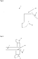
Fig. 2 zeigt schematisch eine Abscheidevorrichtung mit Absaugung und Trennplatte.2 shows schematically a separating device with suction and separating plate. -
Fig. 3 zeigt schematisch eine Abscheidevorrichtung mit Absaugung und Gasstrom.3 shows schematically a separating device with suction and gas flow.
- 11
- Siebplattesieve plate
- 22
- Aufgabebereichtask area
- 33
- Profilierter Bereich der SiebplatteProfiled area of the sieve plate
- 3131
- Senken des profilierten BereichsLowering of the profiled area
- 3232
- Spitzen des profilierten BereichsPeaks of the profiled area
- 44
- Bereich mit SieböffnungenArea with sieve openings
- 4141
- Sieböffnung mit Öffnungswinkel a1Sieve opening with opening angle a1
- 55
- Entnahmebereichpicking area
- 66
- Aufweitung mit Öffnungswinkel a2Widening with opening angle a2
- 77
- Trennplattepartition plate
- 88th
- Absaugungsuction
- 99
- Zuführung Gasstromsupply of gas flow
Die Siebplatte 1 umfasst einen Aufgabebereich 2, in dem das Polysilicium aufgegeben wird. Das Polysilicium kann beispielsweise mittels einer Förderrinne zur Siebanlage befördert und an den Aufgabebereich 2 der Siebplatte 1 abgegeben werden.The
Die Siebplatte 1 umfasst zudem einen profilierten Bereich 3. Dieser profilierte Bereich 3 sieht Rillen oder Nuten oder Vertiefungen anderer Art vor, so dass der profilierte Bereich 3 Senken 31 und Spitzen 32 aufweist.The
Der im Polysilicium enthaltene Feinanteil sammelt sich während der Bewegung des Polysiliciums auf dem profilierten Bereich 3 in den Senken 31 des profilierten Bereichs 3. The fine fraction contained in the polysilicon collects during the movement of the polysilicon on the profiled
Die Siebplatte 1 umfasst - an den profilierten Bereich 3 anschließend - einen Bereich 4 mit Sieböffnungen 41. Die Sieböffnungen 41 sind unmittelbar hinter (In Förderrichtung) den Senken 31 des profilierten Bereichs 3 angeordnet. Dadurch werden die in den Senken 31 des profilierten Bereichs 3 befindlichen Feinanteile des Polysiliciums gezielt zu den Sieböffnungen 41 des Bereichs 4 geführt.The
Die Spitzen 32 des profilierten Bereichs 3 setzen sich vorzugweise auch im Bereich 4 fort, so dass die gesamte Siebplatte 1 profiliert ist, jedoch im Bereich 4 statt Senken 31 Sieböffnungen 41 aufweist.The
Die Abtrennung des Feinanteils erfolgt somit über die Sieböffnungen 41 der Siebplatte 1. Die abgetrennten Feinanteile können beispielsweise durch einen unterhalb der Sieböffnungen 41 der Siebplatte 1 angeordneten Auffangbehälter aufgenommen werden.The fines are thus separated off via the
Größere Bruchstücke werden im profilierten Bereich über die Spitzen 32 zum Entnahmebereich 5 geführt.Larger fragments are guided to the
Die Sieböffnungen 41 weiten sich in Förderrichtung um einen Öffnungswinkel a1. Die Sieböffnungen 41 weisen am Ende des Bereichs 4 eine weitere Aufweitung 6 auf, gekennzeichnet durch einen Öffnungswinkel a2. The
Bei der Abscheidevorrichtung ist in einer bevorzugten Ausführungsform eine Absaugung 8 unterhalb der Sieböffnungen 41 angebracht, die so positioniert ist, dass sich die Absaugung 8 bevorzugt zwischen Anfang der Sieböffnungen 41 und der Trennplatte 7 befindet.In a preferred embodiment of the separating device, a
Eine weitere bevorzugte Ausführungsform der erfindungsgemäßen Abscheidung ist die Installation eines Gasstromes 9 oberhalb der Sieböffnungen 41. Another preferred embodiment of the separation according to the invention is the installation of a
Das vom Polysiliziumhersteller im Beutel angelieferte Polysiliziummaterial enthält auch kleinere Bruchstücke und Feinmaterialien. Das Feinmaterial, insbesondere mit Korngrößen kleiner als 4 mm, hat einen negativen Einfluss auf den Ziehprozess und muss aus diesem Grund vor der Verwendung entfernt werden. Für den Test wurde die Polybruchgröße 2 eingesetzt.The bagged polysilicon material supplied by the polysilicon manufacturer also contains smaller fragments and fines. The fine material, especially with grain sizes smaller than 4 mm, has a negative impact on the drawing process and must therefore be removed before use.
Das für den Test verwendete Polysiliziummaterial mit Polybruchgrößen 2 wurde mit einem Analysesieb (DIN ISO 3310-2) mit einer Nennlochweite W = 4mm (Quadratlochung) abgesiebt und für die Tests zur Verfügung gestellt. Das abgetrennte Feinmaterial wurde aufgefangen und verwogen.The polysilicon material used for the test with fractional poly fractions of 2 was sieved using an analysis sieve (DIN ISO 3310-2) with a nominal hole width W = 4 mm (square holes) and made available for the tests. The separated fine material was collected and weighed.
Auf einer Fördereinheit wurden 10 kg Testpoylsiliciummaterial von der Bruchgröße 2 (ohne Feinmaterial < 4 mm) gegeben. Das Aufgeben des Testpolysiliciummaterials wird bevorzugt über einen Trichter vorgenommen. Der zu befüllende Behälter wird am Ende der Siebstrecke über der ersten Fördereinheit positioniert, so dass das Testpolysiliziummaterial in den Behälter ohne Probleme gefördert werden kann.10 kg of test polysilicon material of fragment size 2 (without fines <4 mm) were placed on a conveyor unit. The loading of the test polysilicon material is preferably done via a hopper. The container to be filled is positioned at the end of the screening section above the first conveyor unit so that the test polysilicon material can be conveyed into the container without any problems.
Das im Vorfeld für den Test abgetrennte Feinmaterial wird für diesen Test verwendet. Beim Befüllen der Fördereinheit werden jeweils nach 2 kg Testpolymaterial 2g abgetrenntes Feinmaterial zugegeben, so dass am Ende in Summe 10g Feinmaterial für diesen Test zugegeben wurde.The fines separated in advance for the test are used for this test. When filling the conveyor unit, 2 g of separated fine material are added after each 2 kg of test polymer material, so that at the end a total of 10 g of fine material was added for this test.
Danach wurden die Fördereinheit und die Siebstrecke gestartet. Die Fördermenge wurde vor dem Test auf 3kg +/- 0,5kg pro Minute eingestellt. Das entfernte Feinmaterial wurde aufgefangen und zurückgewogen. Pro Einstellung wurden die Versuche fünfmal vorgenommen.Then the conveyor unit and the screening section were started. The flow rate was set to 3kg +/- 0.5kg per minute before the test. The fines removed were collected and reweighed. The experiments were carried out five times per setting.
Tabelle 1 zeigt die mittleren Ergebnisse: Table 1 shows the mean results:
Hierfür wurde eine Fördereinheit plus eine Siebstrecke ohne Absaugung und ohne Gasstrom von oben verwendet.A conveyor unit plus a screening section without suction and without gas flow from above was used for this.
Hierfür wurde eine Fördereinheit plus eine Siebstrecke mit Absaugung, aber ohne Gasstrom von oben verwendet.A conveyor unit plus a screening section with suction but without gas flow from above was used for this.
Hierfür wurde eine Fördereinheit plus eine Siebstrecke mit Absaugung und mit einem Gasstrom von oben verwendet.A conveyor unit plus a screening section with suction and a gas stream from above was used for this.
Hierfür wurden zwei Fördereinheiten plus zwei Siebstrecken ohne Absaugung und ohne Gasstrom von oben verwendet, wobei nach jeder Fördereinheit eine Siebstrecke folgte.Two conveyor units plus two screening sections without suction and without gas flow from above were used for this, with a screening section following each conveyor unit.
Hierfür wurden zwei Fördereinheiten plus zwei Siebstrecken mit Absaugung und ohne Gasstrom von oben verwendet, wobei nach jeder Fördereinheit eine Siebstrecke folgte-
Die Ergebnisse zeigen, dass die Verwendung von Absaugung und Gasstrom von oben zu einer Verbesserung der Entfernungsrate um 8% führen.The results show that the use of suction and top gas flow resulted in an 8% improvement in removal rate.
Eine weitere Verbesserung der Entfernungsrate ist möglich, wenn zwei Siebstrecken zum Einsatz kommen und eine Absaugung vorgesehen ist.A further improvement in the removal rate is possible if two screen sections are used and suction is provided.
In einer Ausführungsform umfasst die Abscheidevorrichtung daher zwei Siebplatten, umfassend jeweils einen Aufgabebereich für Polysilicium, einen profilierten Bereich mit Spitzen und Senken, einen an den profilierten Bereich anschließenden Bereich mit Sieböffnungen, und einen Entnahmebereich, wobei sich die Sieböffnungen in Richtung des Entnahmebereichs auf weiten, und eine unterhalb der Sieböffnungen angeordnete Trennplatte, die horizontal und vertikal verschiebbar ist, sowie eine Absaugung unterhalb der Sieböffnungen. Der Entnahmebereich der ersten Siebplatte schließt an den Aufgabebereich der zweiten Siebplatte an, d.h. Polysilicium, das in der ersten Siebstrecke nicht abgetrennt wurde, wird auf die zweite Siebstrecke gegeben. Bei beiden Siebstrecken sind Absaugungen unterhalb der Sieböffnungen vorgesehen.In one embodiment, the separating device therefore comprises two screen plates, each comprising a feed area for polysilicon, a profiled area with peaks and valleys, an area adjoining the profiled area with screen openings, and a removal area, with the screen openings in Widen in the direction of the removal area, and a separating plate arranged below the screen openings, which can be moved horizontally and vertically, and a suction device below the screen openings. The removal area of the first screen plate connects to the feed area of the second screen plate, ie polysilicon that was not separated in the first screen section is fed to the second screen section. In both screen sections, suction is provided below the screen openings.
Die vorstehende Beschreibung beispielhafter Ausführungsformen ist exemplarisch zu verstehen. Die damit erfolgte Offenbarung ermöglicht es dem Fachmann einerseits, die vorliegende Erfindung und die damit verbundenen Vorteile zu verstehen, und umfasst andererseits im Verständnis des Fachmanns auch offensichtliche Abänderungen und Modifikationen der beschriebenen Strukturen und Verfahren.The foregoing description of exemplary embodiments is to be understood as an example. The disclosure thus made will enable those skilled in the art to understand the present invention and the advantages attendant thereto, while also encompassing variations and modifications to the described structures and methods that would become apparent to those skilled in the art.
Der Schutzbereich der Erfindung wird durch die beigefügten Ansprüche begrenzt.The scope of the invention is limited by the appended claims.
Claims (10)
- Separating apparatus for polysilicon with at least one screen plate (1), comprising a feed area (2) for polysilicon, a profiled area (3) with peaks (32) and depressions (31), a region (4) adjoining the profiled region (3) and having sieve openings (41), and a removal region (5), the sieve openings (41) widening in the direction of the removal region (5), characterized in that a separating plate (7) is arranged below the sieve openings, which separating plate (7) can be displaced horizontally in order to adjust the position of the separating plate in the direction of the removal area, and which can be moved vertically to vary the distance to the screen openings.
- The separating apparatus of claim 1, wherein an opening angle of the widening of the screen openings (41) is greater than or equal to 1° and less than or equal to 20°.
- The separating apparatus of claim 2, wherein an opening angle of the widening of the screen openings (41) is greater than or equal to 5° and less than or equal to 15°.
- The separating apparatus according to any one of claims 1 to 3, wherein said screen openings are (41) have a length of 5 mm to 50 mm.
- The separating apparatus according to claim 4, wherein the screen openings (41) have a length of 20 mm to 40 mm.
- The separating apparatus according to any one of claims 1 to 5, wherein the screen openings (41) widen a second time in the direction of the removal region after a first widening, wherein an opening angle of this second widening is 40- 150°.
- The separating apparatus according to claim 6, wherein an opening angle of the second expansion is 60 to 120°.
- The separating apparatus according to any one of claims 1 to 7, comprising a suction device (8) below the screen openings (41).
- The separating apparatus according to any one of claims 1 to 8, comprising means for directing a gas stream (9) from above onto the screen openings (41).
- A method wherein polysilicon is applied to the screen plate (1) of a separating apparatus according to any one of claims 1 to 9, which is vibrated such that the polysilicon is caused to move in the direction of the removal region (5), whereby small-particle polysilicon collects in the depressions (31) of the screen plate (1) and falls through the screen openings (41) of the screen plate (1) via the separating plate (7) into a collecting container and is thereby separated from the fed polysilicon, whereby the fed polysilicon is further processed without the separated small-particle polysilicon.
Applications Claiming Priority (2)
| Application Number | Priority Date | Filing Date | Title |
|---|---|---|---|
| DE102016225248.8A DE102016225248A1 (en) | 2016-12-16 | 2016-12-16 | Separator for polysilicon |
| PCT/EP2017/069199 WO2018108334A1 (en) | 2016-12-16 | 2017-07-28 | Separating device for polycrystalline silicon |
Publications (2)
| Publication Number | Publication Date |
|---|---|
| EP3554723A1 EP3554723A1 (en) | 2019-10-23 |
| EP3554723B1 true EP3554723B1 (en) | 2022-11-30 |
Family
ID=59501437
Family Applications (1)
| Application Number | Title | Priority Date | Filing Date |
|---|---|---|---|
| EP17746082.1A Active EP3554723B1 (en) | 2016-12-16 | 2017-07-28 | Separating device for polycrystalline silicon |
Country Status (9)
| Country | Link |
|---|---|
| US (1) | US11154908B2 (en) |
| EP (1) | EP3554723B1 (en) |
| JP (1) | JP7005627B2 (en) |
| KR (1) | KR102330224B1 (en) |
| CN (1) | CN110072638B (en) |
| DE (1) | DE102016225248A1 (en) |
| FI (1) | FI3554723T3 (en) |
| TW (1) | TWI660793B (en) |
| WO (1) | WO2018108334A1 (en) |
Cited By (1)
| Publication number | Priority date | Publication date | Assignee | Title |
|---|---|---|---|---|
| US12318814B2 (en) | 2023-02-06 | 2025-06-03 | Alztec GmbH | Apparatus and method for flexible classification of polyand/ or monocrystalline silicon |
Families Citing this family (3)
| Publication number | Priority date | Publication date | Assignee | Title |
|---|---|---|---|---|
| KR102800362B1 (en) * | 2020-08-24 | 2025-04-23 | 와커 헤미 아게 | Screen plates for separating devices for bulk material classification |
| US20230392784A1 (en) * | 2020-11-02 | 2023-12-07 | E.On Energiinfrastruktur Ab | Device and method for sorting a particulate stream |
| CN117430119B (en) * | 2023-12-20 | 2024-02-20 | 四川优赛思智能科技有限公司 | An industrial silicon smelting system with automatic eye plugging function |
Citations (9)
| Publication number | Priority date | Publication date | Assignee | Title |
|---|---|---|---|---|
| DE826211C (en) * | 1950-06-13 | 1951-12-27 | Dr Albert Remien | Device for sorting fruit u. like |
| EP0139783A1 (en) * | 1983-11-01 | 1985-05-08 | Ventilatorenfabrik Oelde Gmbh | Device for processing scrap, waste or the like |
| DE4307138A1 (en) * | 1993-03-06 | 1994-09-08 | Seichter Gmbh | Conveyor for bulk goods |
| WO1997026495A2 (en) * | 1996-01-18 | 1997-07-24 | Siemens Aktiengesellschaft | Delivery device |
| US5819951A (en) * | 1996-10-29 | 1998-10-13 | A.S.T. Advanced Screening Technologies Ltd. | Separator plate for the screening of a particulate material and a sorting apparatus comprising same |
| DE19822996C1 (en) * | 1998-05-22 | 1999-04-22 | Siemens Ag | Temperature-resistant gradient material for heat shield or gas turbine blade |
| EP0982081A1 (en) * | 1998-08-27 | 2000-03-01 | Wacker-Chemie GmbH | Pneumatic classification for polysilicon |
| EP1043249A1 (en) * | 1999-04-01 | 2000-10-11 | Wacker-Chemie GmbH | Vibratory conveyor and method for feeding bulk silicium |
| US20150090178A1 (en) * | 2002-02-20 | 2015-04-02 | Arvid Neil Arvidson | Flowable Chips and Methods for the Preparation and Use of Same, and Apparatus for Use in the Methods |
Family Cites Families (13)
| Publication number | Priority date | Publication date | Assignee | Title |
|---|---|---|---|---|
| US2074515A (en) * | 1934-08-11 | 1937-03-23 | Valdis M Pyatt | Separator |
| WO1990009246A1 (en) * | 1989-02-15 | 1990-08-23 | Resource Trend Pty. Ltd. | Air concentrator |
| JPH05168450A (en) | 1991-12-24 | 1993-07-02 | Mitsuwa:Kk | Unmatured soybean sorting machine |
| AUPO638997A0 (en) * | 1997-04-23 | 1997-05-22 | Unisearch Limited | Metal contact scheme using selective silicon growth |
| JP2002011408A (en) | 2000-06-30 | 2002-01-15 | Sumitomo Heavy Ind Ltd | Vibration sieving device |
| US6889846B2 (en) * | 2002-03-15 | 2005-05-10 | Johnson Crushers International | Hybrid screen |
| DE102006035081A1 (en) | 2006-07-28 | 2008-01-31 | Wacker Chemie Ag | Method and apparatus for producing classified polycrystalline silicon fracture in high purity |
| KR100882556B1 (en) * | 2007-06-21 | 2009-02-17 | 주식회사 블루웨일스크린 | Screen bar fixing structure of waste water treatment screen device |
| CN202799718U (en) * | 2012-01-07 | 2013-03-20 | 阿不都克友木·哈地尔 | A threshing and cleaning machine |
| CN104944069A (en) * | 2014-03-24 | 2015-09-30 | 湖北国煤煤矿机械有限公司 | Adjustable screening middle trough |
| DE102015206849A1 (en) | 2015-04-16 | 2016-10-20 | Wacker Chemie Ag | Apparatus and method for classifying and dedusting polysilicon granules |
| DE102015211351A1 (en) | 2015-06-19 | 2016-12-22 | Siltronic Ag | Sieve plate for screening equipment for the mechanical classification of polysilicon |
| CN205161144U (en) * | 2015-12-02 | 2016-04-20 | 蒋和忠 | Harvester with chain vibration isolation sieves device |
-
2016
- 2016-12-16 DE DE102016225248.8A patent/DE102016225248A1/en not_active Withdrawn
-
2017
- 2017-07-28 KR KR1020197020447A patent/KR102330224B1/en active Active
- 2017-07-28 US US16/470,006 patent/US11154908B2/en active Active
- 2017-07-28 WO PCT/EP2017/069199 patent/WO2018108334A1/en not_active Ceased
- 2017-07-28 JP JP2019531776A patent/JP7005627B2/en active Active
- 2017-07-28 FI FIEP17746082.1T patent/FI3554723T3/en active
- 2017-07-28 EP EP17746082.1A patent/EP3554723B1/en active Active
- 2017-07-28 CN CN201780077025.3A patent/CN110072638B/en active Active
- 2017-12-12 TW TW106143595A patent/TWI660793B/en active
Patent Citations (9)
| Publication number | Priority date | Publication date | Assignee | Title |
|---|---|---|---|---|
| DE826211C (en) * | 1950-06-13 | 1951-12-27 | Dr Albert Remien | Device for sorting fruit u. like |
| EP0139783A1 (en) * | 1983-11-01 | 1985-05-08 | Ventilatorenfabrik Oelde Gmbh | Device for processing scrap, waste or the like |
| DE4307138A1 (en) * | 1993-03-06 | 1994-09-08 | Seichter Gmbh | Conveyor for bulk goods |
| WO1997026495A2 (en) * | 1996-01-18 | 1997-07-24 | Siemens Aktiengesellschaft | Delivery device |
| US5819951A (en) * | 1996-10-29 | 1998-10-13 | A.S.T. Advanced Screening Technologies Ltd. | Separator plate for the screening of a particulate material and a sorting apparatus comprising same |
| DE19822996C1 (en) * | 1998-05-22 | 1999-04-22 | Siemens Ag | Temperature-resistant gradient material for heat shield or gas turbine blade |
| EP0982081A1 (en) * | 1998-08-27 | 2000-03-01 | Wacker-Chemie GmbH | Pneumatic classification for polysilicon |
| EP1043249A1 (en) * | 1999-04-01 | 2000-10-11 | Wacker-Chemie GmbH | Vibratory conveyor and method for feeding bulk silicium |
| US20150090178A1 (en) * | 2002-02-20 | 2015-04-02 | Arvid Neil Arvidson | Flowable Chips and Methods for the Preparation and Use of Same, and Apparatus for Use in the Methods |
Cited By (1)
| Publication number | Priority date | Publication date | Assignee | Title |
|---|---|---|---|---|
| US12318814B2 (en) | 2023-02-06 | 2025-06-03 | Alztec GmbH | Apparatus and method for flexible classification of polyand/ or monocrystalline silicon |
Also Published As
| Publication number | Publication date |
|---|---|
| TWI660793B (en) | 2019-06-01 |
| FI3554723T3 (en) | 2023-03-21 |
| DE102016225248A1 (en) | 2018-06-21 |
| US11154908B2 (en) | 2021-10-26 |
| TW201838726A (en) | 2018-11-01 |
| JP7005627B2 (en) | 2022-01-21 |
| EP3554723A1 (en) | 2019-10-23 |
| KR102330224B1 (en) | 2021-11-22 |
| JP2020513313A (en) | 2020-05-14 |
| CN110072638B (en) | 2022-08-26 |
| CN110072638A (en) | 2019-07-30 |
| WO2018108334A1 (en) | 2018-06-21 |
| KR20190097152A (en) | 2019-08-20 |
| US20200086348A1 (en) | 2020-03-19 |
Similar Documents
| Publication | Publication Date | Title |
|---|---|---|
| EP3310499B1 (en) | Process for the mechanical classifying of polysilicon | |
| EP2055395B1 (en) | Method and device for sieving out particles | |
| EP0982081B1 (en) | Pneumatic classification for polysilicon | |
| EP3554723B1 (en) | Separating device for polycrystalline silicon | |
| EP0876851B1 (en) | Optoelectronic grading device | |
| EP0332929B2 (en) | Process and apparatus for fluidized-bed granulation | |
| EP3043929B1 (en) | Classification of polycrystalline silicon | |
| EP2666750B1 (en) | Polycrystalline silicon | |
| DE112010005677B4 (en) | Device for the pneumatic vacuum sifting of bulk goods | |
| EP2730510B1 (en) | Method for packaging of polycrystalline silicon | |
| EP0636322B1 (en) | Feeding device for producing an uniform layer | |
| WO2016165959A1 (en) | Device and method for classifying and dedusting polysilicon granular material | |
| DE68911533T2 (en) | WINIFIFIER FOR PRODUCT PARTICLES. | |
| EP3115151A1 (en) | Recovery of abrasive from abrasive - water jet - cutting installations | |
| DE102005062090B4 (en) | Visual device and method for separating heavy and light particles of tobacco material | |
| DE102008058998B4 (en) | Process for the screening or classification of cut, vegetable bulk material, in particular tobacco, and apparatus for carrying out the process | |
| EP4200085B1 (en) | Screen plate for a separating device for classifying bulk material | |
| EP3403731A1 (en) | Device for homogenizing and separating mixtures of particles | |
| DE3804190A1 (en) | Apparatus for classifying a flow of particles and use of the apparatus | |
| DE872304C (en) | Method and device for classifying powdery material | |
| DE19915122A1 (en) | Riser pipe separator for fluidized bed granulation has a return shaft arranged above the separator | |
| DE1507735B1 (en) | Device for cross-flow sifting of granular material with separation limits below 1 mm and process for their operation |
Legal Events
| Date | Code | Title | Description |
|---|---|---|---|
| STAA | Information on the status of an ep patent application or granted ep patent |
Free format text: STATUS: UNKNOWN |
|
| STAA | Information on the status of an ep patent application or granted ep patent |
Free format text: STATUS: THE INTERNATIONAL PUBLICATION HAS BEEN MADE |
|
| PUAI | Public reference made under article 153(3) epc to a published international application that has entered the european phase |
Free format text: ORIGINAL CODE: 0009012 |
|
| STAA | Information on the status of an ep patent application or granted ep patent |
Free format text: STATUS: REQUEST FOR EXAMINATION WAS MADE |
|
| 17P | Request for examination filed |
Effective date: 20190603 |
|
| AK | Designated contracting states |
Kind code of ref document: A1 Designated state(s): AL AT BE BG CH CY CZ DE DK EE ES FI FR GB GR HR HU IE IS IT LI LT LU LV MC MK MT NL NO PL PT RO RS SE SI SK SM TR |
|
| AX | Request for extension of the european patent |
Extension state: BA ME |
|
| DAV | Request for validation of the european patent (deleted) | ||
| DAX | Request for extension of the european patent (deleted) | ||
| STAA | Information on the status of an ep patent application or granted ep patent |
Free format text: STATUS: EXAMINATION IS IN PROGRESS |
|
| 17Q | First examination report despatched |
Effective date: 20200715 |
|
| RAP1 | Party data changed (applicant data changed or rights of an application transferred) |
Owner name: SILTRONIC AG |
|
| GRAP | Despatch of communication of intention to grant a patent |
Free format text: ORIGINAL CODE: EPIDOSNIGR1 |
|
| STAA | Information on the status of an ep patent application or granted ep patent |
Free format text: STATUS: GRANT OF PATENT IS INTENDED |
|
| INTG | Intention to grant announced |
Effective date: 20220623 |
|
| GRAS | Grant fee paid |
Free format text: ORIGINAL CODE: EPIDOSNIGR3 |
|
| GRAA | (expected) grant |
Free format text: ORIGINAL CODE: 0009210 |
|
| STAA | Information on the status of an ep patent application or granted ep patent |
Free format text: STATUS: THE PATENT HAS BEEN GRANTED |
|
| AK | Designated contracting states |
Kind code of ref document: B1 Designated state(s): AL AT BE BG CH CY CZ DE DK EE ES FI FR GB GR HR HU IE IS IT LI LT LU LV MC MK MT NL NO PL PT RO RS SE SI SK SM TR |
|
| REG | Reference to a national code |
Ref country code: CH Ref legal event code: EP Ref country code: GB Ref legal event code: FG4D Free format text: NOT ENGLISH |
|
| REG | Reference to a national code |
Ref country code: AT Ref legal event code: REF Ref document number: 1534277 Country of ref document: AT Kind code of ref document: T Effective date: 20221215 |
|
| REG | Reference to a national code |
Ref country code: IE Ref legal event code: FG4D Free format text: LANGUAGE OF EP DOCUMENT: GERMAN |
|
| REG | Reference to a national code |
Ref country code: DE Ref legal event code: R096 Ref document number: 502017014160 Country of ref document: DE |
|
| REG | Reference to a national code |
Ref country code: LT Ref legal event code: MG9D |
|
| REG | Reference to a national code |
Ref country code: NL Ref legal event code: MP Effective date: 20221130 |
|
| PG25 | Lapsed in a contracting state [announced via postgrant information from national office to epo] |
Ref country code: SE Free format text: LAPSE BECAUSE OF FAILURE TO SUBMIT A TRANSLATION OF THE DESCRIPTION OR TO PAY THE FEE WITHIN THE PRESCRIBED TIME-LIMIT Effective date: 20221130 Ref country code: PT Free format text: LAPSE BECAUSE OF FAILURE TO SUBMIT A TRANSLATION OF THE DESCRIPTION OR TO PAY THE FEE WITHIN THE PRESCRIBED TIME-LIMIT Effective date: 20230331 Ref country code: NO Free format text: LAPSE BECAUSE OF FAILURE TO SUBMIT A TRANSLATION OF THE DESCRIPTION OR TO PAY THE FEE WITHIN THE PRESCRIBED TIME-LIMIT Effective date: 20230228 Ref country code: LT Free format text: LAPSE BECAUSE OF FAILURE TO SUBMIT A TRANSLATION OF THE DESCRIPTION OR TO PAY THE FEE WITHIN THE PRESCRIBED TIME-LIMIT Effective date: 20221130 Ref country code: ES Free format text: LAPSE BECAUSE OF FAILURE TO SUBMIT A TRANSLATION OF THE DESCRIPTION OR TO PAY THE FEE WITHIN THE PRESCRIBED TIME-LIMIT Effective date: 20221130 |
|
| PG25 | Lapsed in a contracting state [announced via postgrant information from national office to epo] |
Ref country code: RS Free format text: LAPSE BECAUSE OF FAILURE TO SUBMIT A TRANSLATION OF THE DESCRIPTION OR TO PAY THE FEE WITHIN THE PRESCRIBED TIME-LIMIT Effective date: 20221130 Ref country code: PL Free format text: LAPSE BECAUSE OF FAILURE TO SUBMIT A TRANSLATION OF THE DESCRIPTION OR TO PAY THE FEE WITHIN THE PRESCRIBED TIME-LIMIT Effective date: 20221130 Ref country code: LV Free format text: LAPSE BECAUSE OF FAILURE TO SUBMIT A TRANSLATION OF THE DESCRIPTION OR TO PAY THE FEE WITHIN THE PRESCRIBED TIME-LIMIT Effective date: 20221130 Ref country code: IS Free format text: LAPSE BECAUSE OF FAILURE TO SUBMIT A TRANSLATION OF THE DESCRIPTION OR TO PAY THE FEE WITHIN THE PRESCRIBED TIME-LIMIT Effective date: 20230330 Ref country code: HR Free format text: LAPSE BECAUSE OF FAILURE TO SUBMIT A TRANSLATION OF THE DESCRIPTION OR TO PAY THE FEE WITHIN THE PRESCRIBED TIME-LIMIT Effective date: 20221130 Ref country code: GR Free format text: LAPSE BECAUSE OF FAILURE TO SUBMIT A TRANSLATION OF THE DESCRIPTION OR TO PAY THE FEE WITHIN THE PRESCRIBED TIME-LIMIT Effective date: 20230301 |
|
| PG25 | Lapsed in a contracting state [announced via postgrant information from national office to epo] |
Ref country code: NL Free format text: LAPSE BECAUSE OF FAILURE TO SUBMIT A TRANSLATION OF THE DESCRIPTION OR TO PAY THE FEE WITHIN THE PRESCRIBED TIME-LIMIT Effective date: 20221130 |
|
| PG25 | Lapsed in a contracting state [announced via postgrant information from national office to epo] |
Ref country code: SM Free format text: LAPSE BECAUSE OF FAILURE TO SUBMIT A TRANSLATION OF THE DESCRIPTION OR TO PAY THE FEE WITHIN THE PRESCRIBED TIME-LIMIT Effective date: 20221130 Ref country code: RO Free format text: LAPSE BECAUSE OF FAILURE TO SUBMIT A TRANSLATION OF THE DESCRIPTION OR TO PAY THE FEE WITHIN THE PRESCRIBED TIME-LIMIT Effective date: 20221130 Ref country code: EE Free format text: LAPSE BECAUSE OF FAILURE TO SUBMIT A TRANSLATION OF THE DESCRIPTION OR TO PAY THE FEE WITHIN THE PRESCRIBED TIME-LIMIT Effective date: 20221130 Ref country code: DK Free format text: LAPSE BECAUSE OF FAILURE TO SUBMIT A TRANSLATION OF THE DESCRIPTION OR TO PAY THE FEE WITHIN THE PRESCRIBED TIME-LIMIT Effective date: 20221130 Ref country code: CZ Free format text: LAPSE BECAUSE OF FAILURE TO SUBMIT A TRANSLATION OF THE DESCRIPTION OR TO PAY THE FEE WITHIN THE PRESCRIBED TIME-LIMIT Effective date: 20221130 |
|
| PG25 | Lapsed in a contracting state [announced via postgrant information from national office to epo] |
Ref country code: SK Free format text: LAPSE BECAUSE OF FAILURE TO SUBMIT A TRANSLATION OF THE DESCRIPTION OR TO PAY THE FEE WITHIN THE PRESCRIBED TIME-LIMIT Effective date: 20221130 Ref country code: AL Free format text: LAPSE BECAUSE OF FAILURE TO SUBMIT A TRANSLATION OF THE DESCRIPTION OR TO PAY THE FEE WITHIN THE PRESCRIBED TIME-LIMIT Effective date: 20221130 |
|
| REG | Reference to a national code |
Ref country code: DE Ref legal event code: R097 Ref document number: 502017014160 Country of ref document: DE |
|
| PLBE | No opposition filed within time limit |
Free format text: ORIGINAL CODE: 0009261 |
|
| STAA | Information on the status of an ep patent application or granted ep patent |
Free format text: STATUS: NO OPPOSITION FILED WITHIN TIME LIMIT |
|
| 26N | No opposition filed |
Effective date: 20230831 |
|
| PG25 | Lapsed in a contracting state [announced via postgrant information from national office to epo] |
Ref country code: SI Free format text: LAPSE BECAUSE OF FAILURE TO SUBMIT A TRANSLATION OF THE DESCRIPTION OR TO PAY THE FEE WITHIN THE PRESCRIBED TIME-LIMIT Effective date: 20221130 |
|
| PG25 | Lapsed in a contracting state [announced via postgrant information from national office to epo] |
Ref country code: MC Free format text: LAPSE BECAUSE OF FAILURE TO SUBMIT A TRANSLATION OF THE DESCRIPTION OR TO PAY THE FEE WITHIN THE PRESCRIBED TIME-LIMIT Effective date: 20221130 |
|
| PG25 | Lapsed in a contracting state [announced via postgrant information from national office to epo] |
Ref country code: MC Free format text: LAPSE BECAUSE OF FAILURE TO SUBMIT A TRANSLATION OF THE DESCRIPTION OR TO PAY THE FEE WITHIN THE PRESCRIBED TIME-LIMIT Effective date: 20221130 |
|
| REG | Reference to a national code |
Ref country code: CH Ref legal event code: PL |
|
| REG | Reference to a national code |
Ref country code: BE Ref legal event code: MM Effective date: 20230731 |
|
| PG25 | Lapsed in a contracting state [announced via postgrant information from national office to epo] |
Ref country code: LU Free format text: LAPSE BECAUSE OF NON-PAYMENT OF DUE FEES Effective date: 20230728 |
|
| GBPC | Gb: european patent ceased through non-payment of renewal fee |
Effective date: 20230728 |
|
| PG25 | Lapsed in a contracting state [announced via postgrant information from national office to epo] |
Ref country code: LU Free format text: LAPSE BECAUSE OF NON-PAYMENT OF DUE FEES Effective date: 20230728 |
|
| REG | Reference to a national code |
Ref country code: IE Ref legal event code: MM4A |
|
| PG25 | Lapsed in a contracting state [announced via postgrant information from national office to epo] |
Ref country code: GB Free format text: LAPSE BECAUSE OF NON-PAYMENT OF DUE FEES Effective date: 20230728 Ref country code: CH Free format text: LAPSE BECAUSE OF NON-PAYMENT OF DUE FEES Effective date: 20230731 |
|
| PG25 | Lapsed in a contracting state [announced via postgrant information from national office to epo] |
Ref country code: FR Free format text: LAPSE BECAUSE OF NON-PAYMENT OF DUE FEES Effective date: 20230731 Ref country code: BE Free format text: LAPSE BECAUSE OF NON-PAYMENT OF DUE FEES Effective date: 20230731 |
|
| PG25 | Lapsed in a contracting state [announced via postgrant information from national office to epo] |
Ref country code: IE Free format text: LAPSE BECAUSE OF NON-PAYMENT OF DUE FEES Effective date: 20230728 |
|
| PG25 | Lapsed in a contracting state [announced via postgrant information from national office to epo] |
Ref country code: IE Free format text: LAPSE BECAUSE OF NON-PAYMENT OF DUE FEES Effective date: 20230728 |
|
| REG | Reference to a national code |
Ref country code: AT Ref legal event code: MM01 Ref document number: 1534277 Country of ref document: AT Kind code of ref document: T Effective date: 20230728 |
|
| PG25 | Lapsed in a contracting state [announced via postgrant information from national office to epo] |
Ref country code: AT Free format text: LAPSE BECAUSE OF NON-PAYMENT OF DUE FEES Effective date: 20230728 |
|
| PG25 | Lapsed in a contracting state [announced via postgrant information from national office to epo] |
Ref country code: AT Free format text: LAPSE BECAUSE OF NON-PAYMENT OF DUE FEES Effective date: 20230728 |
|
| PG25 | Lapsed in a contracting state [announced via postgrant information from national office to epo] |
Ref country code: BG Free format text: LAPSE BECAUSE OF FAILURE TO SUBMIT A TRANSLATION OF THE DESCRIPTION OR TO PAY THE FEE WITHIN THE PRESCRIBED TIME-LIMIT Effective date: 20221130 |
|
| PG25 | Lapsed in a contracting state [announced via postgrant information from national office to epo] |
Ref country code: BG Free format text: LAPSE BECAUSE OF FAILURE TO SUBMIT A TRANSLATION OF THE DESCRIPTION OR TO PAY THE FEE WITHIN THE PRESCRIBED TIME-LIMIT Effective date: 20221130 |
|
| PG25 | Lapsed in a contracting state [announced via postgrant information from national office to epo] |
Ref country code: CY Free format text: LAPSE BECAUSE OF FAILURE TO SUBMIT A TRANSLATION OF THE DESCRIPTION OR TO PAY THE FEE WITHIN THE PRESCRIBED TIME-LIMIT; INVALID AB INITIO Effective date: 20170728 |
|
| PG25 | Lapsed in a contracting state [announced via postgrant information from national office to epo] |
Ref country code: HU Free format text: LAPSE BECAUSE OF FAILURE TO SUBMIT A TRANSLATION OF THE DESCRIPTION OR TO PAY THE FEE WITHIN THE PRESCRIBED TIME-LIMIT; INVALID AB INITIO Effective date: 20170728 |
|
| PGFP | Annual fee paid to national office [announced via postgrant information from national office to epo] |
Ref country code: FI Payment date: 20250725 Year of fee payment: 9 |
|
| PGFP | Annual fee paid to national office [announced via postgrant information from national office to epo] |
Ref country code: DE Payment date: 20250722 Year of fee payment: 9 |
|
| PGFP | Annual fee paid to national office [announced via postgrant information from national office to epo] |
Ref country code: IT Payment date: 20250724 Year of fee payment: 9 |
|
| PG25 | Lapsed in a contracting state [announced via postgrant information from national office to epo] |
Ref country code: TR Free format text: LAPSE BECAUSE OF FAILURE TO SUBMIT A TRANSLATION OF THE DESCRIPTION OR TO PAY THE FEE WITHIN THE PRESCRIBED TIME-LIMIT Effective date: 20221130 |