EP3553890B1 - Procédé de fabrication d'une connexion entre un terminal de sertissage électromagnétique et un fil électrique - Google Patents
Procédé de fabrication d'une connexion entre un terminal de sertissage électromagnétique et un fil électrique Download PDFInfo
- Publication number
- EP3553890B1 EP3553890B1 EP19167510.7A EP19167510A EP3553890B1 EP 3553890 B1 EP3553890 B1 EP 3553890B1 EP 19167510 A EP19167510 A EP 19167510A EP 3553890 B1 EP3553890 B1 EP 3553890B1
- Authority
- EP
- European Patent Office
- Prior art keywords
- electric wire
- cylindrical portion
- electromagnetic
- side edge
- crimped
- Prior art date
- Legal status (The legal status is an assumption and is not a legal conclusion. Google has not performed a legal analysis and makes no representation as to the accuracy of the status listed.)
- Active
Links
Images


Classifications
-
- H—ELECTRICITY
- H01—ELECTRIC ELEMENTS
- H01R—ELECTRICALLY-CONDUCTIVE CONNECTIONS; STRUCTURAL ASSOCIATIONS OF A PLURALITY OF MUTUALLY-INSULATED ELECTRICAL CONNECTING ELEMENTS; COUPLING DEVICES; CURRENT COLLECTORS
- H01R43/00—Apparatus or processes specially adapted for manufacturing, assembling, maintaining, or repairing of line connectors or current collectors or for joining electric conductors
- H01R43/04—Apparatus or processes specially adapted for manufacturing, assembling, maintaining, or repairing of line connectors or current collectors or for joining electric conductors for forming connections by deformation, e.g. crimping tool
- H01R43/048—Crimping apparatus or processes
-
- B—PERFORMING OPERATIONS; TRANSPORTING
- B21—MECHANICAL METAL-WORKING WITHOUT ESSENTIALLY REMOVING MATERIAL; PUNCHING METAL
- B21D—WORKING OR PROCESSING OF SHEET METAL OR METAL TUBES, RODS OR PROFILES WITHOUT ESSENTIALLY REMOVING MATERIAL; PUNCHING METAL
- B21D26/00—Shaping without cutting otherwise than using rigid devices or tools or yieldable or resilient pads, i.e. applying fluid pressure or magnetic forces
- B21D26/14—Shaping without cutting otherwise than using rigid devices or tools or yieldable or resilient pads, i.e. applying fluid pressure or magnetic forces applying magnetic forces
-
- B—PERFORMING OPERATIONS; TRANSPORTING
- B21—MECHANICAL METAL-WORKING WITHOUT ESSENTIALLY REMOVING MATERIAL; PUNCHING METAL
- B21D—WORKING OR PROCESSING OF SHEET METAL OR METAL TUBES, RODS OR PROFILES WITHOUT ESSENTIALLY REMOVING MATERIAL; PUNCHING METAL
- B21D35/00—Combined processes according to or processes combined with methods covered by groups B21D1/00 - B21D31/00
- B21D35/002—Processes combined with methods covered by groups B21D1/00 - B21D31/00
-
- B—PERFORMING OPERATIONS; TRANSPORTING
- B21—MECHANICAL METAL-WORKING WITHOUT ESSENTIALLY REMOVING MATERIAL; PUNCHING METAL
- B21D—WORKING OR PROCESSING OF SHEET METAL OR METAL TUBES, RODS OR PROFILES WITHOUT ESSENTIALLY REMOVING MATERIAL; PUNCHING METAL
- B21D41/00—Application of procedures in order to alter the diameter of tube ends
- B21D41/04—Reducing; Closing
-
- B—PERFORMING OPERATIONS; TRANSPORTING
- B23—MACHINE TOOLS; METAL-WORKING NOT OTHERWISE PROVIDED FOR
- B23K—SOLDERING OR UNSOLDERING; WELDING; CLADDING OR PLATING BY SOLDERING OR WELDING; CUTTING BY APPLYING HEAT LOCALLY, e.g. FLAME CUTTING; WORKING BY LASER BEAM
- B23K20/00—Non-electric welding by applying impact or other pressure, with or without the application of heat, e.g. cladding or plating
- B23K20/06—Non-electric welding by applying impact or other pressure, with or without the application of heat, e.g. cladding or plating by means of high energy impulses, e.g. magnetic energy
-
- B—PERFORMING OPERATIONS; TRANSPORTING
- B23—MACHINE TOOLS; METAL-WORKING NOT OTHERWISE PROVIDED FOR
- B23K—SOLDERING OR UNSOLDERING; WELDING; CLADDING OR PLATING BY SOLDERING OR WELDING; CUTTING BY APPLYING HEAT LOCALLY, e.g. FLAME CUTTING; WORKING BY LASER BEAM
- B23K20/00—Non-electric welding by applying impact or other pressure, with or without the application of heat, e.g. cladding or plating
- B23K20/22—Non-electric welding by applying impact or other pressure, with or without the application of heat, e.g. cladding or plating taking account of the properties of the materials to be welded
-
- B—PERFORMING OPERATIONS; TRANSPORTING
- B23—MACHINE TOOLS; METAL-WORKING NOT OTHERWISE PROVIDED FOR
- B23K—SOLDERING OR UNSOLDERING; WELDING; CLADDING OR PLATING BY SOLDERING OR WELDING; CUTTING BY APPLYING HEAT LOCALLY, e.g. FLAME CUTTING; WORKING BY LASER BEAM
- B23K20/00—Non-electric welding by applying impact or other pressure, with or without the application of heat, e.g. cladding or plating
- B23K20/24—Preliminary treatment
-
- H—ELECTRICITY
- H01—ELECTRIC ELEMENTS
- H01R—ELECTRICALLY-CONDUCTIVE CONNECTIONS; STRUCTURAL ASSOCIATIONS OF A PLURALITY OF MUTUALLY-INSULATED ELECTRICAL CONNECTING ELEMENTS; COUPLING DEVICES; CURRENT COLLECTORS
- H01R13/00—Details of coupling devices of the kinds covered by groups H01R12/70 or H01R24/00 - H01R33/00
- H01R13/02—Contact members
-
- H—ELECTRICITY
- H01—ELECTRIC ELEMENTS
- H01R—ELECTRICALLY-CONDUCTIVE CONNECTIONS; STRUCTURAL ASSOCIATIONS OF A PLURALITY OF MUTUALLY-INSULATED ELECTRICAL CONNECTING ELEMENTS; COUPLING DEVICES; CURRENT COLLECTORS
- H01R4/00—Electrically-conductive connections between two or more conductive members in direct contact, i.e. touching one another; Means for effecting or maintaining such contact; Electrically-conductive connections having two or more spaced connecting locations for conductors and using contact members penetrating insulation
- H01R4/10—Electrically-conductive connections between two or more conductive members in direct contact, i.e. touching one another; Means for effecting or maintaining such contact; Electrically-conductive connections having two or more spaced connecting locations for conductors and using contact members penetrating insulation effected solely by twisting, wrapping, bending, crimping, or other permanent deformation
- H01R4/18—Electrically-conductive connections between two or more conductive members in direct contact, i.e. touching one another; Means for effecting or maintaining such contact; Electrically-conductive connections having two or more spaced connecting locations for conductors and using contact members penetrating insulation effected solely by twisting, wrapping, bending, crimping, or other permanent deformation by crimping
- H01R4/183—Electrically-conductive connections between two or more conductive members in direct contact, i.e. touching one another; Means for effecting or maintaining such contact; Electrically-conductive connections having two or more spaced connecting locations for conductors and using contact members penetrating insulation effected solely by twisting, wrapping, bending, crimping, or other permanent deformation by crimping for cylindrical elongated bodies, e.g. cables having circular cross-section
-
- H—ELECTRICITY
- H01—ELECTRIC ELEMENTS
- H01R—ELECTRICALLY-CONDUCTIVE CONNECTIONS; STRUCTURAL ASSOCIATIONS OF A PLURALITY OF MUTUALLY-INSULATED ELECTRICAL CONNECTING ELEMENTS; COUPLING DEVICES; CURRENT COLLECTORS
- H01R4/00—Electrically-conductive connections between two or more conductive members in direct contact, i.e. touching one another; Means for effecting or maintaining such contact; Electrically-conductive connections having two or more spaced connecting locations for conductors and using contact members penetrating insulation
- H01R4/10—Electrically-conductive connections between two or more conductive members in direct contact, i.e. touching one another; Means for effecting or maintaining such contact; Electrically-conductive connections having two or more spaced connecting locations for conductors and using contact members penetrating insulation effected solely by twisting, wrapping, bending, crimping, or other permanent deformation
- H01R4/18—Electrically-conductive connections between two or more conductive members in direct contact, i.e. touching one another; Means for effecting or maintaining such contact; Electrically-conductive connections having two or more spaced connecting locations for conductors and using contact members penetrating insulation effected solely by twisting, wrapping, bending, crimping, or other permanent deformation by crimping
- H01R4/20—Electrically-conductive connections between two or more conductive members in direct contact, i.e. touching one another; Means for effecting or maintaining such contact; Electrically-conductive connections having two or more spaced connecting locations for conductors and using contact members penetrating insulation effected solely by twisting, wrapping, bending, crimping, or other permanent deformation by crimping using a crimping sleeve
-
- H—ELECTRICITY
- H01—ELECTRIC ELEMENTS
- H01R—ELECTRICALLY-CONDUCTIVE CONNECTIONS; STRUCTURAL ASSOCIATIONS OF A PLURALITY OF MUTUALLY-INSULATED ELECTRICAL CONNECTING ELEMENTS; COUPLING DEVICES; CURRENT COLLECTORS
- H01R43/00—Apparatus or processes specially adapted for manufacturing, assembling, maintaining, or repairing of line connectors or current collectors or for joining electric conductors
- H01R43/16—Apparatus or processes specially adapted for manufacturing, assembling, maintaining, or repairing of line connectors or current collectors or for joining electric conductors for manufacturing contact members, e.g. by punching and by bending
-
- H—ELECTRICITY
- H01—ELECTRIC ELEMENTS
- H01R—ELECTRICALLY-CONDUCTIVE CONNECTIONS; STRUCTURAL ASSOCIATIONS OF A PLURALITY OF MUTUALLY-INSULATED ELECTRICAL CONNECTING ELEMENTS; COUPLING DEVICES; CURRENT COLLECTORS
- H01R43/00—Apparatus or processes specially adapted for manufacturing, assembling, maintaining, or repairing of line connectors or current collectors or for joining electric conductors
- H01R43/20—Apparatus or processes specially adapted for manufacturing, assembling, maintaining, or repairing of line connectors or current collectors or for joining electric conductors for assembling or disassembling contact members with insulating base, case or sleeve
- H01R43/24—Assembling by moulding on contact members
-
- B—PERFORMING OPERATIONS; TRANSPORTING
- B23—MACHINE TOOLS; METAL-WORKING NOT OTHERWISE PROVIDED FOR
- B23K—SOLDERING OR UNSOLDERING; WELDING; CLADDING OR PLATING BY SOLDERING OR WELDING; CUTTING BY APPLYING HEAT LOCALLY, e.g. FLAME CUTTING; WORKING BY LASER BEAM
- B23K2101/00—Articles made by soldering, welding or cutting
- B23K2101/32—Wires
-
- B—PERFORMING OPERATIONS; TRANSPORTING
- B23—MACHINE TOOLS; METAL-WORKING NOT OTHERWISE PROVIDED FOR
- B23K—SOLDERING OR UNSOLDERING; WELDING; CLADDING OR PLATING BY SOLDERING OR WELDING; CUTTING BY APPLYING HEAT LOCALLY, e.g. FLAME CUTTING; WORKING BY LASER BEAM
- B23K2101/00—Articles made by soldering, welding or cutting
- B23K2101/36—Electric or electronic devices
- B23K2101/38—Conductors
Definitions
- the present disclosure relates to a manufacturing method for a connection between an electromagnetic crimp terminal and an electric wire.
- a terminal plate is crimped onto an end portion of an electric wire of a connecting terminal for transmitting a power supply current and an electric signal.
- Such crimping is known as crimping by mechanical caulking or crimping by metallurgical welding.
- crimping by mechanical caulking a part of the terminal plate bites into an electric conductor forming the electric wire and a periphery of the electric conductor may not be uniformly pressed.
- Reference Document 1 discloses a technique that enables uniform welding is disclosed.
- US 5 824 998 A discloses a method of manufacturing a connection between a terminal and an electric wire by means of a pulsed magnetic force induced by passing a current pulse through a coil.
- an electric wire is crimped to a flat plate portion of a terminal plate, and core wires of the electric wire are loosened and aligned uniformly on the terminal plate. Therefore, the work is complicated and it is difficult to crimp the electric wire (power transmission body) onto a substantially cylindrical portion of the terminal plate while maintaining a substantially columnar shape in a cross section of the electric wire.
- An object of the invention is to provide a method for manufacturing the electromagnetic crimp terminal for lowering the manufacturing cost.
- crimped portions with various diameters are formed from a common terminal plate.
- the cost of the electromagnetic crimp terminal is lowered by promoting common use of members.
- the cylindrical portion can be increased and reduced to various diameters by increasing or reducing the overlapped area in the method for manufacturing the electromagnetic crimp terminal according to the present disclosure
- a common terminal plate can be crimped onto the electric wire having conductor portions with various outer diameters. Therefore, since the types of terminal plate can be reduced and the conductor portions with various diameters can be crimped onto the common terminal plate, the common use of members is promoted, and the manufacturing cost of the electromagnetic crimp terminal can be reduced.
- the crimped portion crimps the exposed portion uniformly in the circumferential direction.
- conductivity between the electric wire and the terminal plate is improved.
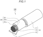
- FIG. 1 is a partial perspective view
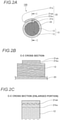
- Fig. 2A is a cross sectional view of a part of a front view
- Fig. 2B is a cross sectional view of a part of side view
- Fig. 2C is an enlarged cross sectional view of the side view showing a part of Fig. 2B .
- an electromagnetic crimp terminal 100 includes: an electric wire 10 including a conductor portion 12 whose periphery is covered with an insulation portion 11; and a terminal plate 20 including a crimped portion 23.
- the crimped portion 23 is electromagnetically crimped (electromagnetic crimping will be described separately in detail) onto a range (hereinafter referred to as "exposed portion") 13 where a part of the insulation portion 11 is peeled off and the conductor portion 12 is exposed.
- a plate-shaped portion 21 (see Fig. 3 ) corresponding to a front foot barrel portion of the terminal plate 20 which is originally a flat plate is formed to have a substantially ⁇ (sigma)-shaped cross section. That is, a vicinity of one side edge 21a (an upper oblique line portion in Fig. 2B ) and a vicinity of the other side edge 21b (a middle oblique line portion in Fig. 2B ) overlap with each other to form a joining boundary 21ab between terminals, and the vicinity of the other side edge 21b and the conductor portion 12 overlap with each other to form a joining boundary 21bc between the terminal and the electric wire.
- both the joining boundary 21ab between the terminals and the joining boundary 21bc between the terminal and the electric wire have wave shapes (see Fig. 2C ).
- the joining boundary 21ab, the joining boundary 21bc and the electric wire are schematically shown by regular wavy lines, but are normally irregularly repeating smooth uneven surfaces.
- the "substantially ⁇ -shaped cross section” not refers to a circular ring having a substantially circular cross section, but refers to a shape having end surfaces spaced apart from each other at one position in a circumferential direction and having one end vicinity and the other end vicinity overlapping each other.
- the crimped portion 23 is formed by a manufacturing method (electromagnetic crimping) described later in a second embodiment, and the one side edge 21a and the other side edge 21b overlap with each other, so that the crimped portion 23 is formed with various inner diameters from the common terminal plate 20 where a shape of the plate-shaped portion 21 is unified. That is, since the common terminal plate 20 is electromagnetically crimped onto the electric wire 10 having the conductor portion 12 with various outer diameters, the types of the terminal plate 20 can be reduced, and thus the manufacturing cost and inventory cost of the member are lowered.
- a shape of the portion of the terminal plate 20 excluding the crimped portion 23 is not limited.
- a portion corresponding to a rear foot barrel portion (see Fig. 3 ) which holds an outer periphery of the insulation portion 11 close to the exposed portion 13 may also has the same form as the crimped portion 23.
- FIG. 3 to Fig. 9 schematically illustrate a method for manufacturing a connection between an electromagnetic crimp terminal and an electric wire according to the invention
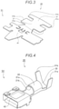
- Fig. 3 is a perspective view of a step (S1) of forming the terminal plate
- Fig. 4 is perspective view of a step (S2) of pressing, bending and forming a part of the terminal plate
- Fig. 5 is a front view showing a part of Fig. 4
- Fig. 6 and Fig. 7 are respectively perspective views during performing and of after completing a step (S3) of inserting a part of the electric wire into a part of the bent and formed terminal plate
- Fig. 3 is a perspective view of a step (S1) of forming the terminal plate
- Fig. 4 is perspective view of a step (S2) of pressing, bending and forming a part of the terminal plate
- Fig. 5 is a front view showing a part of Fig. 4
- Fig. 6 and Fig. 7 are respectively perspective views during performing and of after
- Fig. 8 is a perspective view of a partial cross section of a step (S4) of inserting a part of the terminal plate into a discharge coil
- Fig. 9 is a cross sectional view of a front view of a step (S5) of instantaneously flowing a discharge current.
- the method for manufacturing a connection between an electromagnetic crimp terminal and an electric wire is to manufacture the connection between the electromagnetic crimp terminal 100 and the electric wire 10 by the following steps.
- the terminal plate 20 including a rectangular plate-shaped portion 21 forming the crimped portion 23 is formed (S1).
- the terminal plate 20 includes the plate-shaped portion 21 corresponding to the front foot barrel portion, a rear plate-shaped portion 31 corresponding to the rear foot barrel portion, and a tip plate-shaped portion 41 corresponding to a box-shaped female terminal.
- the form (such as size and shape) of the terminal plate 20 is not limited, and grooves and irregularities may be provided in the plate-shaped portion 21.
- Fig. 4 and Fig. 5 at least the plate-shaped portion 21 is pressed, bent and formed to form a cylindrical portion 22 having a substantially ⁇ -shaped cross section, and the vicinity of the one side edge 21a and the vicinity of the other side edge 21b of the plate-shaped portion 21 overlap with each other (S2).
- the one side edge 21a disposed on an outer side (precisely, an angle portion between the one side edge 21a and an inner surface) is brought into contact (indicated by "contact A" in Fig. 5 ) an outer surface slightly away from the other side edge 21b disposed on an inner side, so that an annular conductive circuit can be formed.
- the contact A may be a single continuous line (having a uniform or non-uniform width) over the entire length of the one side edge 21a, or may be a plurality of intermittent and intermittent lines or a point.
- the rear plate-shaped portion 31 is formed into a substantially U-shaped groove portion 32, and the tip plate-shaped portion 41 is formed into a box-shaped portion 42 having a rectangular cross section.
- the exposed portion 13, which is a part of the conductor portion 12 of the electric wire 10, is inserted into the cylindrical portion 22 (see Figs. 6 and 7 ; S3).
- the cylindrical portion 22, into which the exposed portion 13 is inserted is inserted into a discharge coil 90 having a substantially C-shaped cross section (see Fig. 8 ; S4), and an discharge current i9 instantaneously flows through the discharge coil 90 (see Fig. 9 ; S5).
- the electromagnetic crimp terminal 100 is completed by the electromagnetic force (this will be separately described in detail).
- the cylindrical portion 22 reduced in diameter ( same as the "crimped portion 23") is conductively crimped onto the exposed portion 13 of the electric wire 10, and thus the electromagnetic crimp terminal 100 is manufactured (see Figs. 1 and 2 ).
- the crimped portion 23 is formed into the cylindrical portion 22 having a substantially ⁇ -shaped cross section by pressing, bending and forming the plate-shaped portion 21 which is originally a rectangular plate and then reduced in diameter, the vicinity of the one side edge 21a and the vicinity of the other side edge 21b overlap with each other. Therefore, various diameters can be obtained by increasing or decreasing the overlapped area.
- the common terminal plate 20 having a plate-shaped portion with a uniform shape can be crimped onto the electric wire 10 having the conductor portions 12 with various outer diameters, the types of the terminal plate 20 can be reduced and the manufacturing cost and inventory cost of the member can be reduced.
- the crimped portion 23 and the exposed portion 13 are crimped uniformly in the circumferential direction in electromagnetic crimping.
- the conductivity between the electric wire 10 and the terminal plate 20 is improved.
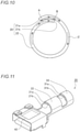
- Fig. 10 and Fig. 11 schematically illustrate the method for manufacturing a connection between an electromagnetic crimp terminal and an electric wire, in which Fig. 10 is a front view of a part of a step (S2) of pressing, bending and forming a part of the terminal plate according to a first modification, and Fig. 11 is a perspective view of a step (S2) of pressing, bending and forming a part of the terminal plate according to a second modification.
- the one side edge 21a disposed on the outer side (precisely, the angle portion between the one side edge 21a and the inner surface) is brought into contact the outer surface slightly away from the other side edge 21b disposed on the inner side
- the other side edge 21b (precisely, an angle portion between the other side edge 21b and the outer surface) is brought into contact with the inner surface slightly away from the one side edge 21a. That is, since the one side edge 21a and the other side edge 21b contact with each other at two positions in the circumferential direction to increase the contact area, the electric resistance with respect to the induced current i2 is lowered, and as a result, the electromagnetic force F is increased.
- the contact in an axial direction of the electromagnetic crimp terminal 100 may be a continuous linear shape or an intermittent linear or dot shape.
- the rear plate-shaped portion 31 in pressing, bending and forming the plate-shaped portion 21 (S2) or before and after pressing, bending and forming the plate-shaped portion 21 (S2), the rear plate-shaped portion 31 is pressed, bent and formed to into a rear cylindrical portion 33 having substantially ⁇ -shaped cross section, and a vicinity of one side edge 31a and a vicinity of the other side edge 31b in the rear plate-shaped portion 31 overlap with each other. That is, in steps same as the above steps (S3 to S5) in the front foot barrel portion, the rear foot barrel portion is also formed to hold the insulation portion 11 of the electric wire 10 by the electromagnetic force.
- a discharge coil (not shown) for the rear cylindrical portion 33 may be provided, or the discharge coil 90 for the cylindrical portion 22 may be used for electromagnetically forming the rear cylindrical portion 33.
- the front foot barrel portion and the rear foot barrel portion can be formed by a processing device using same principle, the working process and working device are simplified, and the manufacturing cost is lowered.
- the crimped portion 23 is formed into the cylindrical portion 22 having a substantially ⁇ -shaped cross section by pressing, bending and forming the plate-shaped portion 21 which is originally a rectangular plate and then reduced in diameter, the vicinity of the one side edge 21a and the vicinity of the other side edge 21b overlap with each other. Therefore, various diameters can be obtained by increasing or decreasing the overlapped area.
- the common terminal plate 20 having a plate-shaped portion with a uniform shape can be crimped onto the electric wire 10 having the conductor portions 12 with various outer diameters, the types of the terminal plate 20 can be reduced and the manufacturing cost and inventory cost of the member can be reduced.
- the crimped portion 23 and the exposed portion 13 are crimped uniformly in the circumferential direction in electromagnetic crimping.
- the conductivity between the electric wire 10 and the terminal plate 20 is improved.
- the diameter reduction of the cylindrical portion 22 formed to have a substantially ⁇ -shaped cross section is not the only means of electromagnetic crimping.
- the types of the terminal plate 20 can be reduced and the manufacturing cost and inventory cost of the member can be lowered by providing the cylindrical portion 22 formed to have a substantially ⁇ -shaped cross section.
- the present invention can be widely used as various crimp terminals, various methods for manufacturing a crimp terminal, and various connecting terminals.
Landscapes
- Engineering & Computer Science (AREA)
- Mechanical Engineering (AREA)
- Manufacturing & Machinery (AREA)
- Physics & Mathematics (AREA)
- Fluid Mechanics (AREA)
- Connections Effected By Soldering, Adhesion, Or Permanent Deformation (AREA)
- Manufacturing Of Electrical Connectors (AREA)
Claims (2)
- Procédé de fabrication d'une connexion entre un terminal de sertissage électromagnétique (100) et un fil électrique (10), le fil électrique (10) incluant une partie conductrice (12) dont une périphérie est couverte d'une partie isolante (11), et le terminal de sertissage électromagnétique (100) présente une plaque de terminal (20) incluant une partie sertie (23) qui peut être sertie sur la partie conductrice (12) du fil électrique (10), le procédé de fabrication comprenant :préparation de la plaque de terminal (20) incluant une partie de plaque plate rectangulaire pour constituer la partie sertie (23) ;constitution de la partie de plaque plate dans une partie cylindrique (22), et chevauchement d'une proximité d'une première arête latérale (21a) de la partie cylindrique (22) et d'une proximité d'une deuxième arête latérale (21b) de la partie cylindrique (22) l'une sur l'autre, de sorte que la partie cylindrique (22) configure un circuit conducteur annulaire avant une diminution d'un diamètre de la partie cylindrique (22) ;insertion d'une partie exposée (13), qui constitue une partie de la partie conductrice (12) du fil électrique (10) exposée par retrait par pelage d'une partie de la partie isolante (11), dans la partie cylindrique (22) ;insertion de la partie cylindrique (22) dans laquelle la partie exposée (13) est insérée dans une bobine de décharge (90) présentant une section transversale substantiellement en forme de C ;déclenchement d'un écoulement instantané d'un courant de décharge à travers la bobine de décharge (90), et diminution du diamètre de la partie cylindrique (22) par une force électromagnétique fondée sur un courant induit et un champ magnétique induit, et sertissage par conduction de la partie sertie (23) sur la partie exposée (13), dans lequel le courant induit est généré dans la partie cylindrique (22) du fait du courant de décharge, et le champ magnétique induit est généré entre la bobine de décharge (90) et la partie cylindrique (22) du fait du courant induit,dans lequel la première arête latérale (21a) est en contact avec une surface extérieure de la partie cylindrique (22) proche de la deuxième arête latérale (21b), avant une diminution du diamètre de la partie cylindrique (22), et/oula deuxième arête latérale (21b) est en contact avec une surface intérieure de la partie cylindrique (22) proche de la première arête latérale (21a), avant une diminution du diamètre de la partie cylindrique (22).
- Le procédé de fabrication selon la revendication 1, dans lequel la partie sertie (23) présente une section transversale substantiellement en forme de σ dans une section transversale perpendiculaire à une direction dans laquelle le fil électrique (10) s'étend.
Applications Claiming Priority (1)
| Application Number | Priority Date | Filing Date | Title |
|---|---|---|---|
| JP2018076927A JP6793148B2 (ja) | 2018-04-12 | 2018-04-12 | 電磁圧接端子の製造方法 |
Publications (2)
| Publication Number | Publication Date |
|---|---|
| EP3553890A1 EP3553890A1 (fr) | 2019-10-16 |
| EP3553890B1 true EP3553890B1 (fr) | 2022-01-19 |
Family
ID=66101905
Family Applications (1)
| Application Number | Title | Priority Date | Filing Date |
|---|---|---|---|
| EP19167510.7A Active EP3553890B1 (fr) | 2018-04-12 | 2019-04-05 | Procédé de fabrication d'une connexion entre un terminal de sertissage électromagnétique et un fil électrique |
Country Status (4)
| Country | Link |
|---|---|
| US (1) | US10958029B2 (fr) |
| EP (1) | EP3553890B1 (fr) |
| JP (1) | JP6793148B2 (fr) |
| CN (1) | CN110380239B (fr) |
Families Citing this family (1)
| Publication number | Priority date | Publication date | Assignee | Title |
|---|---|---|---|---|
| CN117015908A (zh) * | 2021-03-25 | 2023-11-07 | 株式会社自动网络技术研究所 | 带端子电线、带端子电线的制造方法 |
Citations (1)
| Publication number | Priority date | Publication date | Assignee | Title |
|---|---|---|---|---|
| JP3207597U (ja) * | 2016-09-08 | 2016-11-17 | 株式会社三英社製作所 | 圧縮端子 |
Family Cites Families (24)
| Publication number | Priority date | Publication date | Assignee | Title |
|---|---|---|---|---|
| US3404368A (en) * | 1965-08-04 | 1968-10-01 | Amp Inc | Electrical connector of the plug or socket variety |
| JP3096804B2 (ja) * | 1995-11-20 | 2000-10-10 | 日本航空電子工業株式会社 | ケーブルコネクタ用コンタクト、コンタクトアセンブリ、多芯ケーブルコネクタおよび圧着工具 |
| JP2000507159A (ja) * | 1995-12-20 | 2000-06-13 | パルサー・ウェルディング・リミテッド | 金属対象物の電磁気的一体化または結合 |
| US5824998A (en) * | 1995-12-20 | 1998-10-20 | Pulsar Welding Ltd. | Joining or welding of metal objects by a pulsed magnetic force |
| IL119679A (en) * | 1996-11-24 | 2001-08-08 | Pulsar Welding Ltd | Electromagnetic forming apparatus |
| US5966813A (en) * | 1997-12-23 | 1999-10-19 | Dana Corporation | Method for joining vehicle frame components |
| US6137094A (en) * | 1998-09-29 | 2000-10-24 | Kistersky; Ludmila | External inductor for magnetic-pulse welding and forming |
| DE60111935T2 (de) * | 2000-04-26 | 2006-04-20 | Cosma International Inc., Concord | Verfahren zum hydroformen einer rohrförmigen struktur mit unterschiedlichen durchmessern aus einem rohrförmigen rohling, beim magnetimpuls-schweissen |
| IL149873A0 (en) * | 2001-05-31 | 2002-11-10 | Dana Corp | Method for performing a magnetic pulse welding operation |
| US6875964B2 (en) * | 2002-05-07 | 2005-04-05 | Ford Motor Company | Apparatus for electromagnetic forming, joining and welding |
| EP2472675B1 (fr) * | 2003-07-30 | 2020-09-30 | The Furukawa Electric Co., Ltd. | Structure de sertissage de borne et procédé de sertissage de borne sur un fil électrique en aluminium |
| IL163974A0 (en) * | 2003-09-10 | 2005-12-18 | Dana Corp | Method for monitoring the performance of a magnetic pulse forming or welding process |
| KR20070001105A (ko) * | 2004-01-26 | 2007-01-03 | 펄사르 웰딩 엘티디. | 드라이브 샤프트 제조 방법 및 장치 |
| US7127816B2 (en) * | 2004-03-04 | 2006-10-31 | Dana Corporation | Method of permanently joining first and second metallic components |
| US7364062B2 (en) * | 2004-10-19 | 2008-04-29 | American Axle & Manufacturing, Inc. | Magnetic pulse welding of steel propshafts |
| US7513025B2 (en) * | 2004-12-28 | 2009-04-07 | The Boeing Company | Magnetic field concentrator for electromagnetic forming |
| JP4644559B2 (ja) | 2005-08-08 | 2011-03-02 | 矢崎総業株式会社 | 電磁溶接方法 |
| JP5103137B2 (ja) * | 2007-11-01 | 2012-12-19 | 株式会社オートネットワーク技術研究所 | 圧着端子、端子付電線及びその製造方法 |
| JP2010021015A (ja) * | 2008-07-10 | 2010-01-28 | Sumitomo Wiring Syst Ltd | 端子金具及び端子付き電線 |
| JP5717395B2 (ja) | 2010-10-14 | 2015-05-13 | 矢崎総業株式会社 | 防水型圧着端子の圧着方法 |
| JP6060015B2 (ja) * | 2013-03-19 | 2017-01-11 | 矢崎総業株式会社 | 圧着端子の電線に対する圧着構造 |
| JP6454062B2 (ja) * | 2013-03-21 | 2019-01-16 | 矢崎総業株式会社 | 圧着端子 |
| JP5462394B2 (ja) | 2013-05-13 | 2014-04-02 | 株式会社三英社製作所 | 圧縮スリーブを用いた電線の接続方法及び当該圧縮スリーブ |
| CN104201535B (zh) * | 2014-08-04 | 2018-10-16 | 重庆市光学机械研究所 | 电缆线导体与接线端子焊接的方法 |
-
2018
- 2018-04-12 JP JP2018076927A patent/JP6793148B2/ja active Active
-
2019
- 2019-04-04 US US16/375,205 patent/US10958029B2/en active Active
- 2019-04-05 EP EP19167510.7A patent/EP3553890B1/fr active Active
- 2019-04-12 CN CN201910293264.3A patent/CN110380239B/zh active Active
Patent Citations (1)
| Publication number | Priority date | Publication date | Assignee | Title |
|---|---|---|---|---|
| JP3207597U (ja) * | 2016-09-08 | 2016-11-17 | 株式会社三英社製作所 | 圧縮端子 |
Also Published As
| Publication number | Publication date |
|---|---|
| CN110380239B (zh) | 2021-08-24 |
| US20190319418A1 (en) | 2019-10-17 |
| JP2019186082A (ja) | 2019-10-24 |
| US10958029B2 (en) | 2021-03-23 |
| EP3553890A1 (fr) | 2019-10-16 |
| JP6793148B2 (ja) | 2020-12-02 |
| CN110380239A (zh) | 2019-10-25 |
Similar Documents
| Publication | Publication Date | Title |
|---|---|---|
| JP5654242B2 (ja) | 電線の端末処理方法 | |
| CN107453182B (zh) | 具有端子的电线的制造方法 | |
| CN106849553A (zh) | 定子线圈形成方法 | |
| EP2485330A1 (fr) | Pose de terminal et son procédé de connexion | |
| JP6652583B2 (ja) | 端子付き電線 | |
| US20210050677A1 (en) | Terminal and wire with terminal | |
| US20090011663A1 (en) | Coaxial cable end-processing structure, coaxial cable shielding terminal and press-fastening apparatus | |
| KR20150121013A (ko) | 통 형상체, 압착 단자, 및 이들의 제조 방법, 그리고 압착 단자의 제조 장치 | |
| US20200287300A1 (en) | Connection Terminal, Method Of Connecting Wires Using The Same And Pressing Die | |
| CN106532308A (zh) | 具有改进的连接凸部几何形状的金属片材零件 | |
| CN110323581A (zh) | 带端子的电线 | |
| US10038292B2 (en) | Method for connecting insulated wires | |
| JP2015041509A (ja) | 導電路及び電線 | |
| EP3553890B1 (fr) | Procédé de fabrication d'une connexion entre un terminal de sertissage électromagnétique et un fil électrique | |
| US10644415B2 (en) | Terminal-equipped wire and method for crimping terminal onto wire | |
| JP2017204355A (ja) | 端子付き電線及び端子 | |
| WO2017141866A1 (fr) | Dispositif de sertissage de borne, outil de sertissage de borne, et procédé de fabrication de fil électrique à borne sertie | |
| JPH09139238A (ja) | 電線接続方法 | |
| KR20160119689A (ko) | 코일단말의 접속구조 | |
| US6287158B1 (en) | Contact element | |
| JP2012059440A (ja) | シールド電線の端末構造 | |
| CN115117647A (zh) | 带端子的电线 | |
| JP5151936B2 (ja) | 端子金具及びその製造方法 | |
| JP6560695B2 (ja) | 接続方法 | |
| JP6609136B2 (ja) | 圧着接続構造、圧着接続装置及び圧着接続方法 |
Legal Events
| Date | Code | Title | Description |
|---|---|---|---|
| PUAI | Public reference made under article 153(3) epc to a published international application that has entered the european phase |
Free format text: ORIGINAL CODE: 0009012 |
|
| STAA | Information on the status of an ep patent application or granted ep patent |
Free format text: STATUS: REQUEST FOR EXAMINATION WAS MADE |
|
| 17P | Request for examination filed |
Effective date: 20190405 |
|
| AK | Designated contracting states |
Kind code of ref document: A1 Designated state(s): AL AT BE BG CH CY CZ DE DK EE ES FI FR GB GR HR HU IE IS IT LI LT LU LV MC MK MT NL NO PL PT RO RS SE SI SK SM TR |
|
| AX | Request for extension of the european patent |
Extension state: BA ME |
|
| STAA | Information on the status of an ep patent application or granted ep patent |
Free format text: STATUS: EXAMINATION IS IN PROGRESS |
|
| 17Q | First examination report despatched |
Effective date: 20200923 |
|
| GRAP | Despatch of communication of intention to grant a patent |
Free format text: ORIGINAL CODE: EPIDOSNIGR1 |
|
| STAA | Information on the status of an ep patent application or granted ep patent |
Free format text: STATUS: GRANT OF PATENT IS INTENDED |
|
| RIC1 | Information provided on ipc code assigned before grant |
Ipc: B23K 101/38 20060101ALN20211018BHEP Ipc: B23K 101/32 20060101ALN20211018BHEP Ipc: B21D 26/14 20060101ALN20211018BHEP Ipc: B23K 20/22 20060101ALI20211018BHEP Ipc: B23K 20/24 20060101ALI20211018BHEP Ipc: B23K 20/06 20060101ALI20211018BHEP Ipc: H01R 43/048 20060101ALI20211018BHEP Ipc: H01R 4/18 20060101AFI20211018BHEP |
|
| RIC1 | Information provided on ipc code assigned before grant |
Ipc: B23K 101/38 20060101ALN20211101BHEP Ipc: B23K 101/32 20060101ALN20211101BHEP Ipc: B21D 26/14 20060101ALN20211101BHEP Ipc: B23K 20/22 20060101ALI20211101BHEP Ipc: B23K 20/24 20060101ALI20211101BHEP Ipc: B23K 20/06 20060101ALI20211101BHEP Ipc: H01R 43/048 20060101ALI20211101BHEP Ipc: H01R 4/18 20060101AFI20211101BHEP |
|
| GRAS | Grant fee paid |
Free format text: ORIGINAL CODE: EPIDOSNIGR3 |
|
| INTG | Intention to grant announced |
Effective date: 20211117 |
|
| GRAA | (expected) grant |
Free format text: ORIGINAL CODE: 0009210 |
|
| STAA | Information on the status of an ep patent application or granted ep patent |
Free format text: STATUS: THE PATENT HAS BEEN GRANTED |
|
| AK | Designated contracting states |
Kind code of ref document: B1 Designated state(s): AL AT BE BG CH CY CZ DE DK EE ES FI FR GB GR HR HU IE IS IT LI LT LU LV MC MK MT NL NO PL PT RO RS SE SI SK SM TR |
|
| REG | Reference to a national code |
Ref country code: GB Ref legal event code: FG4D |
|
| REG | Reference to a national code |
Ref country code: CH Ref legal event code: EP |
|
| REG | Reference to a national code |
Ref country code: DE Ref legal event code: R096 Ref document number: 602019010971 Country of ref document: DE |
|
| REG | Reference to a national code |
Ref country code: AT Ref legal event code: REF Ref document number: 1464318 Country of ref document: AT Kind code of ref document: T Effective date: 20220215 |
|
| REG | Reference to a national code |
Ref country code: IE Ref legal event code: FG4D |
|
| REG | Reference to a national code |
Ref country code: LT Ref legal event code: MG9D |
|
| REG | Reference to a national code |
Ref country code: NL Ref legal event code: MP Effective date: 20220119 |
|
| REG | Reference to a national code |
Ref country code: AT Ref legal event code: MK05 Ref document number: 1464318 Country of ref document: AT Kind code of ref document: T Effective date: 20220119 |
|
| PG25 | Lapsed in a contracting state [announced via postgrant information from national office to epo] |
Ref country code: NL Free format text: LAPSE BECAUSE OF FAILURE TO SUBMIT A TRANSLATION OF THE DESCRIPTION OR TO PAY THE FEE WITHIN THE PRESCRIBED TIME-LIMIT Effective date: 20220119 |
|
| PG25 | Lapsed in a contracting state [announced via postgrant information from national office to epo] |
Ref country code: SE Free format text: LAPSE BECAUSE OF FAILURE TO SUBMIT A TRANSLATION OF THE DESCRIPTION OR TO PAY THE FEE WITHIN THE PRESCRIBED TIME-LIMIT Effective date: 20220119 Ref country code: RS Free format text: LAPSE BECAUSE OF FAILURE TO SUBMIT A TRANSLATION OF THE DESCRIPTION OR TO PAY THE FEE WITHIN THE PRESCRIBED TIME-LIMIT Effective date: 20220119 Ref country code: PT Free format text: LAPSE BECAUSE OF FAILURE TO SUBMIT A TRANSLATION OF THE DESCRIPTION OR TO PAY THE FEE WITHIN THE PRESCRIBED TIME-LIMIT Effective date: 20220519 Ref country code: NO Free format text: LAPSE BECAUSE OF FAILURE TO SUBMIT A TRANSLATION OF THE DESCRIPTION OR TO PAY THE FEE WITHIN THE PRESCRIBED TIME-LIMIT Effective date: 20220419 Ref country code: LT Free format text: LAPSE BECAUSE OF FAILURE TO SUBMIT A TRANSLATION OF THE DESCRIPTION OR TO PAY THE FEE WITHIN THE PRESCRIBED TIME-LIMIT Effective date: 20220119 Ref country code: HR Free format text: LAPSE BECAUSE OF FAILURE TO SUBMIT A TRANSLATION OF THE DESCRIPTION OR TO PAY THE FEE WITHIN THE PRESCRIBED TIME-LIMIT Effective date: 20220119 Ref country code: ES Free format text: LAPSE BECAUSE OF FAILURE TO SUBMIT A TRANSLATION OF THE DESCRIPTION OR TO PAY THE FEE WITHIN THE PRESCRIBED TIME-LIMIT Effective date: 20220119 Ref country code: BG Free format text: LAPSE BECAUSE OF FAILURE TO SUBMIT A TRANSLATION OF THE DESCRIPTION OR TO PAY THE FEE WITHIN THE PRESCRIBED TIME-LIMIT Effective date: 20220419 |
|
| PG25 | Lapsed in a contracting state [announced via postgrant information from national office to epo] |
Ref country code: PL Free format text: LAPSE BECAUSE OF FAILURE TO SUBMIT A TRANSLATION OF THE DESCRIPTION OR TO PAY THE FEE WITHIN THE PRESCRIBED TIME-LIMIT Effective date: 20220119 Ref country code: LV Free format text: LAPSE BECAUSE OF FAILURE TO SUBMIT A TRANSLATION OF THE DESCRIPTION OR TO PAY THE FEE WITHIN THE PRESCRIBED TIME-LIMIT Effective date: 20220119 Ref country code: GR Free format text: LAPSE BECAUSE OF FAILURE TO SUBMIT A TRANSLATION OF THE DESCRIPTION OR TO PAY THE FEE WITHIN THE PRESCRIBED TIME-LIMIT Effective date: 20220420 Ref country code: FI Free format text: LAPSE BECAUSE OF FAILURE TO SUBMIT A TRANSLATION OF THE DESCRIPTION OR TO PAY THE FEE WITHIN THE PRESCRIBED TIME-LIMIT Effective date: 20220119 Ref country code: AT Free format text: LAPSE BECAUSE OF FAILURE TO SUBMIT A TRANSLATION OF THE DESCRIPTION OR TO PAY THE FEE WITHIN THE PRESCRIBED TIME-LIMIT Effective date: 20220119 |
|
| PG25 | Lapsed in a contracting state [announced via postgrant information from national office to epo] |
Ref country code: IS Free format text: LAPSE BECAUSE OF FAILURE TO SUBMIT A TRANSLATION OF THE DESCRIPTION OR TO PAY THE FEE WITHIN THE PRESCRIBED TIME-LIMIT Effective date: 20220519 |
|
| REG | Reference to a national code |
Ref country code: DE Ref legal event code: R097 Ref document number: 602019010971 Country of ref document: DE |
|
| PG25 | Lapsed in a contracting state [announced via postgrant information from national office to epo] |
Ref country code: SM Free format text: LAPSE BECAUSE OF FAILURE TO SUBMIT A TRANSLATION OF THE DESCRIPTION OR TO PAY THE FEE WITHIN THE PRESCRIBED TIME-LIMIT Effective date: 20220119 Ref country code: SK Free format text: LAPSE BECAUSE OF FAILURE TO SUBMIT A TRANSLATION OF THE DESCRIPTION OR TO PAY THE FEE WITHIN THE PRESCRIBED TIME-LIMIT Effective date: 20220119 Ref country code: RO Free format text: LAPSE BECAUSE OF FAILURE TO SUBMIT A TRANSLATION OF THE DESCRIPTION OR TO PAY THE FEE WITHIN THE PRESCRIBED TIME-LIMIT Effective date: 20220119 Ref country code: EE Free format text: LAPSE BECAUSE OF FAILURE TO SUBMIT A TRANSLATION OF THE DESCRIPTION OR TO PAY THE FEE WITHIN THE PRESCRIBED TIME-LIMIT Effective date: 20220119 Ref country code: DK Free format text: LAPSE BECAUSE OF FAILURE TO SUBMIT A TRANSLATION OF THE DESCRIPTION OR TO PAY THE FEE WITHIN THE PRESCRIBED TIME-LIMIT Effective date: 20220119 Ref country code: CZ Free format text: LAPSE BECAUSE OF FAILURE TO SUBMIT A TRANSLATION OF THE DESCRIPTION OR TO PAY THE FEE WITHIN THE PRESCRIBED TIME-LIMIT Effective date: 20220119 |
|
| PLBE | No opposition filed within time limit |
Free format text: ORIGINAL CODE: 0009261 |
|
| STAA | Information on the status of an ep patent application or granted ep patent |
Free format text: STATUS: NO OPPOSITION FILED WITHIN TIME LIMIT |
|
| PG25 | Lapsed in a contracting state [announced via postgrant information from national office to epo] |
Ref country code: AL Free format text: LAPSE BECAUSE OF FAILURE TO SUBMIT A TRANSLATION OF THE DESCRIPTION OR TO PAY THE FEE WITHIN THE PRESCRIBED TIME-LIMIT Effective date: 20220119 |
|
| REG | Reference to a national code |
Ref country code: CH Ref legal event code: PL |
|
| 26N | No opposition filed |
Effective date: 20221020 |
|
| REG | Reference to a national code |
Ref country code: BE Ref legal event code: MM Effective date: 20220430 |
|
| PG25 | Lapsed in a contracting state [announced via postgrant information from national office to epo] |
Ref country code: MC Free format text: LAPSE BECAUSE OF FAILURE TO SUBMIT A TRANSLATION OF THE DESCRIPTION OR TO PAY THE FEE WITHIN THE PRESCRIBED TIME-LIMIT Effective date: 20220119 Ref country code: LU Free format text: LAPSE BECAUSE OF NON-PAYMENT OF DUE FEES Effective date: 20220405 Ref country code: LI Free format text: LAPSE BECAUSE OF NON-PAYMENT OF DUE FEES Effective date: 20220430 Ref country code: FR Free format text: LAPSE BECAUSE OF NON-PAYMENT OF DUE FEES Effective date: 20220430 Ref country code: CH Free format text: LAPSE BECAUSE OF NON-PAYMENT OF DUE FEES Effective date: 20220430 |
|
| PG25 | Lapsed in a contracting state [announced via postgrant information from national office to epo] |
Ref country code: SI Free format text: LAPSE BECAUSE OF FAILURE TO SUBMIT A TRANSLATION OF THE DESCRIPTION OR TO PAY THE FEE WITHIN THE PRESCRIBED TIME-LIMIT Effective date: 20220119 Ref country code: BE Free format text: LAPSE BECAUSE OF NON-PAYMENT OF DUE FEES Effective date: 20220430 |
|
| PG25 | Lapsed in a contracting state [announced via postgrant information from national office to epo] |
Ref country code: IE Free format text: LAPSE BECAUSE OF NON-PAYMENT OF DUE FEES Effective date: 20220405 |
|
| PG25 | Lapsed in a contracting state [announced via postgrant information from national office to epo] |
Ref country code: IT Free format text: LAPSE BECAUSE OF FAILURE TO SUBMIT A TRANSLATION OF THE DESCRIPTION OR TO PAY THE FEE WITHIN THE PRESCRIBED TIME-LIMIT Effective date: 20220119 |
|
| GBPC | Gb: european patent ceased through non-payment of renewal fee |
Effective date: 20230405 |
|
| PG25 | Lapsed in a contracting state [announced via postgrant information from national office to epo] |
Ref country code: GB Free format text: LAPSE BECAUSE OF NON-PAYMENT OF DUE FEES Effective date: 20230405 |
|
| PG25 | Lapsed in a contracting state [announced via postgrant information from national office to epo] |
Ref country code: GB Free format text: LAPSE BECAUSE OF NON-PAYMENT OF DUE FEES Effective date: 20230405 |
|
| PG25 | Lapsed in a contracting state [announced via postgrant information from national office to epo] |
Ref country code: HU Free format text: LAPSE BECAUSE OF FAILURE TO SUBMIT A TRANSLATION OF THE DESCRIPTION OR TO PAY THE FEE WITHIN THE PRESCRIBED TIME-LIMIT; INVALID AB INITIO Effective date: 20190405 |
|
| PG25 | Lapsed in a contracting state [announced via postgrant information from national office to epo] |
Ref country code: MK Free format text: LAPSE BECAUSE OF FAILURE TO SUBMIT A TRANSLATION OF THE DESCRIPTION OR TO PAY THE FEE WITHIN THE PRESCRIBED TIME-LIMIT Effective date: 20220119 Ref country code: CY Free format text: LAPSE BECAUSE OF FAILURE TO SUBMIT A TRANSLATION OF THE DESCRIPTION OR TO PAY THE FEE WITHIN THE PRESCRIBED TIME-LIMIT Effective date: 20220119 |
|
| PG25 | Lapsed in a contracting state [announced via postgrant information from national office to epo] |
Ref country code: MT Free format text: LAPSE BECAUSE OF FAILURE TO SUBMIT A TRANSLATION OF THE DESCRIPTION OR TO PAY THE FEE WITHIN THE PRESCRIBED TIME-LIMIT Effective date: 20220119 |
|
| PGFP | Annual fee paid to national office [announced via postgrant information from national office to epo] |
Ref country code: DE Payment date: 20250305 Year of fee payment: 7 |
|
| PG25 | Lapsed in a contracting state [announced via postgrant information from national office to epo] |
Ref country code: TR Free format text: LAPSE BECAUSE OF FAILURE TO SUBMIT A TRANSLATION OF THE DESCRIPTION OR TO PAY THE FEE WITHIN THE PRESCRIBED TIME-LIMIT Effective date: 20220119 |