EP3552948B1 - Navigation method for ship, and ship - Google Patents
Navigation method for ship, and ship Download PDFInfo
- Publication number
- EP3552948B1 EP3552948B1 EP17878610.9A EP17878610A EP3552948B1 EP 3552948 B1 EP3552948 B1 EP 3552948B1 EP 17878610 A EP17878610 A EP 17878610A EP 3552948 B1 EP3552948 B1 EP 3552948B1
- Authority
- EP
- European Patent Office
- Prior art keywords
- power
- equipment
- ship
- port
- return
- Prior art date
- Legal status (The legal status is an assumption and is not a legal conclusion. Google has not performed a legal analysis and makes no representation as to the accuracy of the status listed.)
- Active
Links
- 238000000034 method Methods 0.000 title claims description 14
- 238000005286 illumination Methods 0.000 claims description 16
- 238000004378 air conditioning Methods 0.000 claims description 7
- 238000010411 cooking Methods 0.000 claims description 7
- 239000003651 drinking water Substances 0.000 claims description 7
- 235000020188 drinking water Nutrition 0.000 claims description 7
- 230000008014 freezing Effects 0.000 claims description 7
- 238000007710 freezing Methods 0.000 claims description 7
- 238000010586 diagram Methods 0.000 description 20
- 230000001419 dependent effect Effects 0.000 description 18
- 238000012423 maintenance Methods 0.000 description 7
- 230000007704 transition Effects 0.000 description 5
- XLYOFNOQVPJJNP-UHFFFAOYSA-N water Substances O XLYOFNOQVPJJNP-UHFFFAOYSA-N 0.000 description 3
- 230000008033 biological extinction Effects 0.000 description 2
- 238000002485 combustion reaction Methods 0.000 description 2
- 239000002828 fuel tank Substances 0.000 description 2
- 230000006872 improvement Effects 0.000 description 2
- 230000002265 prevention Effects 0.000 description 2
- 230000008901 benefit Effects 0.000 description 1
- 238000004891 communication Methods 0.000 description 1
- 238000011161 development Methods 0.000 description 1
- 230000000694 effects Effects 0.000 description 1
- 239000000446 fuel Substances 0.000 description 1
- 238000009413 insulation Methods 0.000 description 1
- 238000002955 isolation Methods 0.000 description 1
- 238000012986 modification Methods 0.000 description 1
- 230000004048 modification Effects 0.000 description 1
- 230000008439 repair process Effects 0.000 description 1
- 238000011160 research Methods 0.000 description 1
- IHQKEDIOMGYHEB-UHFFFAOYSA-M sodium dimethylarsinate Chemical class [Na+].C[As](C)([O-])=O IHQKEDIOMGYHEB-UHFFFAOYSA-M 0.000 description 1
Images


Classifications
-
- B—PERFORMING OPERATIONS; TRANSPORTING
- B63—SHIPS OR OTHER WATERBORNE VESSELS; RELATED EQUIPMENT
- B63J—AUXILIARIES ON VESSELS
- B63J3/00—Driving of auxiliaries
- B63J3/04—Driving of auxiliaries from power plant other than propulsion power plant
-
- B—PERFORMING OPERATIONS; TRANSPORTING
- B63—SHIPS OR OTHER WATERBORNE VESSELS; RELATED EQUIPMENT
- B63B—SHIPS OR OTHER WATERBORNE VESSELS; EQUIPMENT FOR SHIPPING
- B63B43/00—Improving safety of vessels, e.g. damage control, not otherwise provided for
-
- B—PERFORMING OPERATIONS; TRANSPORTING
- B63—SHIPS OR OTHER WATERBORNE VESSELS; RELATED EQUIPMENT
- B63B—SHIPS OR OTHER WATERBORNE VESSELS; EQUIPMENT FOR SHIPPING
- B63B45/00—Arrangements or adaptations of signalling or lighting devices
-
- B—PERFORMING OPERATIONS; TRANSPORTING
- B63—SHIPS OR OTHER WATERBORNE VESSELS; RELATED EQUIPMENT
- B63H—MARINE PROPULSION OR STEERING
- B63H21/00—Use of propulsion power plant or units on vessels
- B63H21/12—Use of propulsion power plant or units on vessels the vessels being motor-driven
- B63H21/17—Use of propulsion power plant or units on vessels the vessels being motor-driven by electric motor
-
- B—PERFORMING OPERATIONS; TRANSPORTING
- B63—SHIPS OR OTHER WATERBORNE VESSELS; RELATED EQUIPMENT
- B63J—AUXILIARIES ON VESSELS
- B63J3/00—Driving of auxiliaries
- B63J3/02—Driving of auxiliaries from propulsion power plant
-
- B—PERFORMING OPERATIONS; TRANSPORTING
- B63—SHIPS OR OTHER WATERBORNE VESSELS; RELATED EQUIPMENT
- B63J—AUXILIARIES ON VESSELS
- B63J99/00—Subject matter not provided for in other groups of this subclass
-
- H—ELECTRICITY
- H02—GENERATION; CONVERSION OR DISTRIBUTION OF ELECTRIC POWER
- H02J—CIRCUIT ARRANGEMENTS OR SYSTEMS FOR SUPPLYING OR DISTRIBUTING ELECTRIC POWER; SYSTEMS FOR STORING ELECTRIC ENERGY
- H02J9/00—Circuit arrangements for emergency or stand-by power supply, e.g. for emergency lighting
- H02J9/04—Circuit arrangements for emergency or stand-by power supply, e.g. for emergency lighting in which the distribution system is disconnected from the normal source and connected to a standby source
- H02J9/06—Circuit arrangements for emergency or stand-by power supply, e.g. for emergency lighting in which the distribution system is disconnected from the normal source and connected to a standby source with automatic change-over, e.g. UPS systems
-
- B—PERFORMING OPERATIONS; TRANSPORTING
- B63—SHIPS OR OTHER WATERBORNE VESSELS; RELATED EQUIPMENT
- B63H—MARINE PROPULSION OR STEERING
- B63H21/00—Use of propulsion power plant or units on vessels
- B63H21/20—Use of propulsion power plant or units on vessels the vessels being powered by combinations of different types of propulsion units
- B63H2021/202—Use of propulsion power plant or units on vessels the vessels being powered by combinations of different types of propulsion units of hybrid electric type
- B63H2021/205—Use of propulsion power plant or units on vessels the vessels being powered by combinations of different types of propulsion units of hybrid electric type the second power unit being of the internal combustion engine type, or the like, e.g. a Diesel engine
-
- B—PERFORMING OPERATIONS; TRANSPORTING
- B63—SHIPS OR OTHER WATERBORNE VESSELS; RELATED EQUIPMENT
- B63H—MARINE PROPULSION OR STEERING
- B63H21/00—Use of propulsion power plant or units on vessels
- B63H21/20—Use of propulsion power plant or units on vessels the vessels being powered by combinations of different types of propulsion units
- B63H2021/202—Use of propulsion power plant or units on vessels the vessels being powered by combinations of different types of propulsion units of hybrid electric type
- B63H2021/207—Use of propulsion power plant or units on vessels the vessels being powered by combinations of different types of propulsion units of hybrid electric type the second power unit being a gas turbine
-
- B—PERFORMING OPERATIONS; TRANSPORTING
- B63—SHIPS OR OTHER WATERBORNE VESSELS; RELATED EQUIPMENT
- B63J—AUXILIARIES ON VESSELS
- B63J3/00—Driving of auxiliaries
- B63J2003/001—Driving of auxiliaries characterised by type of power supply, or power transmission, e.g. by using electric power or steam
- B63J2003/002—Driving of auxiliaries characterised by type of power supply, or power transmission, e.g. by using electric power or steam by using electric power
-
- Y—GENERAL TAGGING OF NEW TECHNOLOGICAL DEVELOPMENTS; GENERAL TAGGING OF CROSS-SECTIONAL TECHNOLOGIES SPANNING OVER SEVERAL SECTIONS OF THE IPC; TECHNICAL SUBJECTS COVERED BY FORMER USPC CROSS-REFERENCE ART COLLECTIONS [XRACs] AND DIGESTS
- Y02—TECHNOLOGIES OR APPLICATIONS FOR MITIGATION OR ADAPTATION AGAINST CLIMATE CHANGE
- Y02E—REDUCTION OF GREENHOUSE GAS [GHG] EMISSIONS, RELATED TO ENERGY GENERATION, TRANSMISSION OR DISTRIBUTION
- Y02E10/00—Energy generation through renewable energy sources
- Y02E10/50—Photovoltaic [PV] energy
-
- Y—GENERAL TAGGING OF NEW TECHNOLOGICAL DEVELOPMENTS; GENERAL TAGGING OF CROSS-SECTIONAL TECHNOLOGIES SPANNING OVER SEVERAL SECTIONS OF THE IPC; TECHNICAL SUBJECTS COVERED BY FORMER USPC CROSS-REFERENCE ART COLLECTIONS [XRACs] AND DIGESTS
- Y02—TECHNOLOGIES OR APPLICATIONS FOR MITIGATION OR ADAPTATION AGAINST CLIMATE CHANGE
- Y02E—REDUCTION OF GREENHOUSE GAS [GHG] EMISSIONS, RELATED TO ENERGY GENERATION, TRANSMISSION OR DISTRIBUTION
- Y02E10/00—Energy generation through renewable energy sources
- Y02E10/70—Wind energy
-
- Y—GENERAL TAGGING OF NEW TECHNOLOGICAL DEVELOPMENTS; GENERAL TAGGING OF CROSS-SECTIONAL TECHNOLOGIES SPANNING OVER SEVERAL SECTIONS OF THE IPC; TECHNICAL SUBJECTS COVERED BY FORMER USPC CROSS-REFERENCE ART COLLECTIONS [XRACs] AND DIGESTS
- Y02—TECHNOLOGIES OR APPLICATIONS FOR MITIGATION OR ADAPTATION AGAINST CLIMATE CHANGE
- Y02T—CLIMATE CHANGE MITIGATION TECHNOLOGIES RELATED TO TRANSPORTATION
- Y02T70/00—Maritime or waterways transport
- Y02T70/50—Measures to reduce greenhouse gas emissions related to the propulsion system
- Y02T70/5218—Less carbon-intensive fuels, e.g. natural gas, biofuels
- Y02T70/5236—Renewable or hybrid-electric solutions
Definitions
- the present invention relates to a navigation method for a ship, and a ship.
- a main engine, a generator, or the like required for obtaining thrust of the ship is accommodated inside a ship body of a ship.
- the main engine or the generator is disposed inside an engine room.
- a plurality of engine rooms may be provided in order to secure redundancy.
- emergency equipment such as a fire pump, a drainage pump, and emergency illumination using an emergency generator provided independently of the engine room, and fire or flood subsides.
- a generator main generator in an engine room where fire or flood does not occur is operated, whereby power is fed to return-to-port equipment required for returning to a port, and self-dependent navigation is enabled.
- Japanese Unexamined Patent Application Publication No. 2003-137168 JP H11 266 532 discloses to reduce the size and weight of the equipment as a whole and further save energy.
- This document provides rectifiers, which are installed on the output side of AC generators and an emergency AC generator, and a bus is constituted as a DC bus.
- a large apparatus such as an active filter which has been necessary for eliminating higher harmonics which are generated on a bus can be omitted. Since the bus is the DC bus, a battery can be connected. Thereby it is made unnecessary to always operate the emergency AC generator on standby, so that energy can be saved.
- JP 2000 280 987 A discloses to improve fire prevention and safety by providing an upper housing box body vertically and wind/rain-tightly divisible into two parts via a joint, providing a lower box body having a leg part supported on a deck, and housing required devices such as a generator, a fuel tank and a distribution panel inside these. Therefore, an independent emergency generating set for a ship is composed of an upper housing box body and a lower housing box bod, and these are formed as a wind/rain-tight housing box vertically divisible into two parts via a joint. An upper part of an intake division, an upper part of an exhaust division and an upper part of a maintenance division are formed in the upper housing box body.
- the vessel can have a hull, a keel with a keel cooler, skegs, watertight interior bulkheads, a main deck, topsides, insulation, sonar tubes, a sonar transducer, an engine room, a propulsion system, propellers and rudders that are operable independently and in tandem, engines with vibration isolation mounts, fuel tanks, a hydraulic bow thruster, generators, a pilothouse, a navigation station, a steering device, a dog house, living quarters, a communication system, lighting, escape hatches, and a knuckle boom crane.
- EP 3 046 206 A1 describes an arrangement for power distribution on a vessel, comprising: a first DC bus operating at a first medium voltage; at least one second DC bus operating at a second medium voltage and having no direct connection with the first DC bus; a first AC bus operating at a low voltage; a first inverter coupled between the first DC bus and the first AC bus for allowing power flow from the first DC bus to the first AC bus in a first operation mode; a second AC bus operating at the low voltage; a second inverter coupled between the second DC bus and the second AC bus for allowing power flow from the second DC bus to the second AC bus in the first operation mode; a low voltage connection system for selectively connecting or disconnecting the first AC bus and the second AC bus. Further state of the art is disclosed in EP 3 498 584 A1
- power to be fed to the return-to-port equipment may be short only with the generator in the engine room where fire or flood does not occur.
- power to be fed may be short.
- a generator provided in each engine room increases in capacity or the number of generators increases, thereby securing power feeding ability.
- an increase in capacity of the generator or in the number of generators results in an increase in equipment cost, an increase in weight, confinement of a space inside the ship, or the like.
- An object of the invention is to provide a navigation method for a ship, and a ship capable of suppressing shortage of a power feeding amount in returning to a port through self-dependent navigation after fire or flood occurs while suppressing an increase in equipment cost and an increase in weight.
- the emergency generator may feed power to at least a part of the living quarter appliances.
- the main generators feed power to at least a part of the navigation equipment and another part of the living quarter appliances.
- the invention in normal navigation, it is possible to feed power from the plurality of main generators to the navigation equipment and the living quarter appliance through the first power feeding line.
- fire, flood, or the like it is possible to feed power from the emergency generator to the emergency equipment through the second power feeding line.
- the ship is made to return to the port in a state in which fire or flood has been stopped, it is possible to feed power from the emergency generator to the return-to-port equipment through the third power feeding line.
- the main generator may be provided in a lower portion inside the ship body, and the emergency generator may be provided in a part equal to or higher than an upper deck of the ship body.
- the return-to-port equipment is connected to the first power feeding line and the third power feeding line to allow power switching.
- Fig. 1 is a side view showing the overall configuration of a ship according to the embodiment of the invention.
- a ship 1A of the embodiment includes a ship body 2, main generators 20A and 20B, and an emergency generator 30.
- a ship type of a ship to which the invention can be applied is not limited to a specific ship type, and for example, various ship types, such as a ferry, a roll-on/roll-off ship (RORO ship), and a pure car & truck carrier (PCTC), can be employed.
- the ship body 2 has a pair of broadsides 2s provided on both sides in a ship width direction, and a ship bottom 2b.
- the ship body 2 includes a freeboard deck 3, a lower deck 4, and an upper deck 5 inside thereof.
- the freeboard deck 3 is provided at an interval upward of the ship bottom 2b of the ship body 2.
- the lower deck 4 is provided between the ship bottom 2b and the freeboard deck 3 to form a double bottom in a lower portion of the ship body 2.
- the upper deck 5 is provided at an interval upward of the freeboard deck 3.
- On the upper deck 5, an upper structure 6 having a plurality of layers in an up-down direction is provided.
- the ship body 2 includes a screw 7 below the ship bottom 2b in a stern part 2A.
- the screw 7 is rotationally driven by a propulsion motor 11 provided inside the ship body 2.
- the main generators 20A and 20B are provided inside engine rooms 8A and 8B provided in a lower portion inside the ship body 2.
- the engine rooms 8A and 8B are formed between the lower deck 4 and the freeboard deck 3 inside the ship body 2.
- the engine rooms 8A and 8B are separated from each other by a transverse bulkhead 9 provided at an interval in a bow and stern direction FA of connecting the stern part 2A and a bow part 2F.
- a plurality of main generators 20A are provided inside the engine room 8A.
- a plurality of main generators 20B are provided inside the engine room 8B.
- the main generators 20A and 20B each primarily include, for example, an internal combustion engine part (not shown), such as a gas turbine or a diesel engine, and a generator part (not shown) . In the main generators 20A and 20B combust fuel in the internal combustion engine part and drive the generator part to generate power.
- an internal combustion engine part such as a gas turbine or a diesel engine
- a generator part not shown
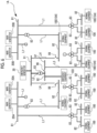
- Fig. 2 is a diagram showing a power feeding system from the main generators and the emergency generator in a ship according to a first embodiment of the invention.
- Fig. 3 is a block diagram showing an example of various kinds of equipment provided in the ship.
- the main generators 20A and 20B each feed power to normal equipment 100 for use in normal navigation.
- the normal equipment 100 includes navigation equipment 101 and living quarter appliances 102.
- the navigation equipment 101 include a propulsion motor 11, a steering system 12, and the like.
- the living quarter appliances 102 include air conditioning equipment 21, a refrigerating and freezing system 22, a drinking water facility 23, and a toilet drainage facility 24 provided inside the ship 1A, a living quarter facility 25, a cooking facility 26, and a general illumination 27 as various kinds of equipment provided in living quarters, and the like.
- the emergency generator 30 is disposed in the upper structure 6. Specifically, the emergency generator 30 is disposed in an uppermost portion of the upper structure 6 on the stern part 2A side.
- the emergency generator 30 is able to feed power to emergency equipment 103 when fire or flood occurs in at least the engine room 8A or the engine room 8B.
- the emergency generator 30 may feed power to each predetermined part inside the ship 1A at the time of anchorage, at the time of restoration from a dead ship state in which the entire ship 1A is powered off, or the like.
- the emergency generator 30 has facility capacity (or rated output) smaller than that of the main generators 20A and 20B.
- the emergency generator 30 illustrated in the embodiment has a rated voltage (hundreds of volts) lower than a rated voltage (for example, thousands of volts) of the main generators 20A and 20B.
- examples of the emergency equipment 103 include a drainage pump 31 that discharges water entering the ship body 2 to the outside of the ship, a ballast pump 32 that improves inclination of the ship body 2 in the bow and stern direction FA or the ship width direction, a fire pump 33, an emergency illumination 34, and the like.
- the emergency equipment 103 is operated with power fed from the emergency generator 30, whereby occurred fire or flood has subsided.
- the ship 1A uses the main generators 20A or the main generators 20B and the emergency generator 30 in combination after fire or flood occurred in the engine room 8A or the engine room 8B has subsided, thereby navigating to the port in a self-dependent manner.
- the ship 1A includes first power feeding lines L1, a second power feeding line L2, and a third power feeding line L3.
- the first power feeding lines L1 connect the normal equipment 100 (the navigation equipment 101 and the living quarter appliances 102) to the plurality of main generators 20A and 20B.
- the main generators 20A and 20B are connected to a plurality of first power feeding lines L1 through generator-side switchboards 81 and 81.
- Each first power feeding line L1 is connected to equipment-side switchboards 82 to which various kinds of normal equipment 100 are connected.
- a voltage to be output from the main generators 20A or the main generators 20B is deboosted to a predetermined voltage (for example, several hundreds of volts) by a transformer 83 provided in the first power feeding line L1.
- Voltage values of a plurality of equipment-side switchboards 82 to which power is fed from the main generators 20A and 20B include a plurality of different voltage values.
- Each of various kinds of normal equipment 100 is connected to the equipment-side switchboard 82 having the voltage value according to a rated voltage of the normal equipment 100.
- the second power feeding line L2 connects the emergency equipment 103 to the emergency generator 30.
- the emergency generator 30 is connected to the second power feeding line L2 through a generator-side switchboard 91.
- the second power feeding line L2 is connected to an equipment-side switchboard 92 to which various kinds of emergency equipment 103 are connected.
- power to be output from the emergency generator 30 is deboosted (or boosted) to a predetermined voltage according to the rated voltage of the emergency equipment 103 by a transformer 93 provided in the second power feeding line L2 and fed.
- the third power feeding line L3 connects, to the emergency generator 30, return-to-port equipment 104 for use in navigation for making the ship 1A return to the port in a state in which fire or flood has been stopped.
- the return-to-port equipment 104 is, for example, the living quarter appliances 102 including the air conditioning equipment 21, the refrigerating and freezing system 22, the drinking water facility 23, the toilet drainage facility 24, the living quarter facility 25, the cooking facility 26, the general illumination 27, and the like described above.
- the return-to-port equipment 104 does not need to be all of the living quarter appliances 102, and for example, a part of the air conditioning equipment 21, the refrigerating and freezing system 22, the drinking water facility 23, the toilet drainage facility 24, the living quarter facility 25, the cooking facility 26, and the general illumination 27.
- the third power feeding line L3 is connected to the equipment-side switchboard 92 provided in the second power feeding line L2 through a switch 96 and an equipment-side switchboard 97.
- the return-to-port equipment 104 to which the third power feeding line L3 is connected may double as the normal equipment 100.
- the first power feeding line L1 and the third power feeding line L3 are connected to the return-to-port equipment 104, thereby allowing power switching.
- power can be fed to the return-to-port equipment 104 through the first power feeding line L1
- navigation for making the ship 1A return to the port in a state in which fire or flood has been stopped power can be fed to the return-to-port equipment 104 through the third power feeding line L3.
- Fig. 4 is a diagram showing a flow in a case where fire or flood occurs in an engine room in navigation of the ship according to the first embodiment of the invention.
- Fig. 5 is a diagram showing a power feeding state in normal navigation of the ship according to the first embodiment of the invention.
- Fig. 6 is a diagram showing a power feeding state when fire or flood occurs in the ship according to the first embodiment of the invention.
- Fig. 7 is a diagram showing a power feeding state in returning to the port through self-dependent navigation after fire or flood has subsided in the ship according to the first embodiment of the invention.
- Step S1 of Fig. 4 the emergency generator 30 is stopped, and power is fed only from the main generators 20A and 20B provided in the engine rooms 8A and 8B. Specifically, as indicated by a bold line in Fig. 5 , power output from the main generators 20A and 20B is fed to the normal equipment 100 (the navigation equipment 101 and the living quarter appliances 102) through the generator-side switchboards 81, the first power feeding lines L1, the transformers 83, the equipment-side switchboards 82. With this, the propulsion motor 11, the steering system 12, and the like constituting the navigation equipment 101 are operated to make the ship 1A navigate, and the living quarter appliances 102 of the respective parts inside the ship 1A are enabled.
- the propulsion motor 11, the steering system 12, and the like constituting the navigation equipment 101 are operated to make the ship 1A navigate, and the living quarter appliances 102 of the respective parts inside the ship 1A are enabled.
- Step S3 power feeding from the main generators 20A and 20B is stopped, and transition is made to an emergency power feeding step in which power is fed from the emergency generator 30 to the emergency equipment 103 (Step S3) .
- power to be output from the emergency generator 30 is fed to the emergency equipment 103 through the generator-side switchboard 91, the second power feeding line L2, the transformer 93, and the equipment-side switchboard 92.
- the switch 96 of the third power feeding line L3 is brought into an open state, and the equipment-side switchboard 92 of the second power feeding line L2 and the equipment-side switchboard 97 of the third power feeding line L3 are electrically disconnected.
- the drainage pump 31, the ballast pump 32, and the fire pump 33 are selectively operated with power fed from the emergency generator 30 in this way as necessary, thereby performing drainage of water entering the ship body 2, improvement of inclination of the ship body 2, and extinction of fire. Furthermore, minimum illumination inside the ship 1A is performed with the emergency illumination 34. In addition, at least the steering system 12 is operated with power to be fed from the emergency generator 30, thereby preventing drifting or the like of the ship 1A.
- Step S5 the operations of the drainage pump 31, the ballast pump 32, the fire pump 33, and the emergency illumination 34 of the emergency equipment 103 are stopped, and transition is made to a return-to-port power feeding step in which a self-dependent navigation step of the ship 1A is performed.
- the switch 96 is brought into a closed state, and the equipment-side switchboard 92 of the second power feeding line L2 and the equipment-side switchboard 97 of the third power feeding line L3 are electrically connected.
- power fed from the emergency generator 30 can be fed to the return-to-port equipment 104 through the generator-side switchboard 91, the second power feeding line L2, the equipment-side switchboard 92, the switch 96, the equipment-side switchboard 97, and the third power feeding line L3.
- the main generators 20A or 20B (in the example of Fig. 7 , the main generator 20B of the engine room 8B) provided in the other engine room of the engine room 8A and the engine room 8B, that is, the engine room where fire or flood does not occur are operated, and power is fed to equipment at least required for returning to the port through self-dependent navigation, for example, the navigation equipment 101.
- the propulsion motor 11, the steering system 12, and the like constituting the navigation equipment 101 are operated, thereby making the ship 1A navigate in a self-dependent manner.
- the main generators 20A and 20B may feed power only to at least a part of the navigation equipment 101, for example, the propulsion motor 11, and the emergency generator 30 may feed power to the steering system 12.
- the emergency generator 30 can feed power only to a part of the living quarter appliances 102 as the return-to-port equipment 104, and the main generators 20A and 20B can feed power another part of the living quarter appliances 102.
- power is fed to the return-to-port equipment 104 required for navigation for returning to the port using the emergency generator 30 after fire or flood has subsided, whereby it is possible to secure power required for operating the return-to-port equipment 104.
- the emergency generator 30 feeds power to at least a part of the living quarter appliances 102. With this, it is possible to feed power to a part of equipment required for living quarters within the ship body 2 using the emergency generator 30 in returning to the port after fire or flood has subsided.
- the main generators 20A and 20B feed power to at least a part of the navigation equipment 101, it is possible to feed power to the minimum navigation equipment 101 required for returning to the port using the main generators 20A and 20B.
- the main generators 20A and 20B can feed power another part of the living quarter appliances 102 excluding a part of the living quarter appliances 102 to which power is fed from the emergency generator 30. With this, it is possible to feed power to the equipment required for living quarters inside the ship body 2 using the main generators 20A and 20B and the emergency generator 30 in returning to the port after fire or flood has subsided.
- the main generators 20A and 20B are provided in a lower portion inside the ship body 2, and the emergency generator 30 is provided in the upper structure 6 that is a part equal to or higher than the upper deck 5 of the ship body 2. With this, even though fire or flood occurs in the engine rooms 8A and 8B where the main generators 20A and 20B, it is possible to operate the emergency generator 30 to feed power while suppressing the influence of fire or flood. Accordingly, it is possible to reliably execute subsidence of fire or flood and return-to-port of the ship 1A after fire or flood has subsided.
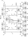
- Fig. 8 is a diagram showing a power feeding system from main generators and an emergency generator in a ship according to a second embodiment of the invention.
- Fig. 9 is a diagram showing a power feeding state in normal navigation of the ship according to the second embodiment of the invention.
- Fig. 10 is a diagram showing a power feeding state when fire or flood occurs in the ship according to the second embodiment of the invention.
- Fig. 11 is a diagram showing a power feeding state in returning to a port through self-dependent navigation after fire or flood has subsided in the ship according to the second embodiment of the invention.
- a ship 1B of the embodiment does not include the third power feeding line L3, the switch 96, and the equipment-side switchboard 97 in contrast to the configuration shown in the first embodiment.
- third power feeding lines L4 that connect the generator-side switchboard 91 connected to the emergency generator 30 and a part of the equipment-side switchboards 82 are provided.
- switches 99 are provided in the third power feeding lines L4.
- the generator-side switchboard 91 and the equipment-side switchboards 82 can be electrically connected and disconnected by the switches 99.
- power to be output from the main generators 20A and 20B is fed to the normal equipment 100 (the navigation equipment 101 and the living quarter appliances 102) through the generator-side switchboards 81, the first power feeding lines L1, the transformers 83, and the equipment-side switchboards 82.
- the propulsion motor 11, the steering system 12, and the like constituting the navigation equipment 101 are operated, the ship 1B is made to navigate, and power is fed to the living quarter appliances 102 of the parts inside the ship 1B.
- Step S2 of Fig. 4 power feeding from the main generators 20A and 20B is stopped, and transition is made to the emergency power feeding step in which power is fed from the emergency generator 30 to the emergency equipment 103 (see Step S3 of Fig. 4 ). With this, power to be output from the emergency generator 30 is fed to the emergency equipment 103 through the generator-side switchboard 91, the second power feeding line L2, the transformer 93, and the equipment-side switchboard 92.
- the drainage pump 31, the ballast pump 32, and the fire pump 33 are selectively operated with power fed from the emergency generator 30 in this way as necessary, thereby performing drainage of water entering the ship body 2, improvement of inclination of the ship body 2, and extinction of fire. Furthermore, minimum illumination inside the ship 1B is performed with the emergency illumination 34. In addition, at least the steering system 12 is operated with power to be fed from the emergency generator 30, thereby preventing drifting or the like of the ship 1B.
- Step S4 of Fig. 4 the operations of the drainage pump 31, the ballast pump 32, the fire pump 33, and the emergency illumination 34 of the emergency equipment 103 are stopped, and transition is made to a return-to-port power feeding step in which a self-dependent navigation step of the ship 1B is performed (see Step S5 of Fig. 4 ).
- the switch 99 of the third power feeding line L4 is brought into a closed state, and the generator-side switchboard 91 and the equipment-side switchboard 82 are connected through the third power feeding line L4.
- power fed from the emergency generator 30 is fed to the normal equipment 100 constituting the return-to-port equipment 104 through the generator-side switchboard 91, the third power feeding line L4, and the equipment-side switchboard 82.
- the emergency generator 30 feeds power to equipment having small load fluctuation in the return-to-port equipment 104, for example, the living quarter appliances 102 and the steering system 12 in the navigation equipment 101.
- the emergency generator 30 has facility capacity (or rated output) lower than that of the main generators 20A and 20B.
- power is fed to the return-to-port equipment 104 required for navigation for returning to the port using using the main generators 20A and 20B and the emergency generator 30, instead of only the main generators 20A and 20B, after fire or flood has subsided, whereby it is possible to increase power capable of being fed to the return-to-port equipment 104.
- the invention is not limited to the above-described embodiments, and includes embodiments obtained by modifying the above-described embodiments in various ways. That is, the specific shapes, configurations, or the like exemplified in the embodiments are merely examples, and can be appropriately modified.
- a power feeding destination from the emergency generator 30 and the main generators 20A and 20B is illustrated in return-to-port power feeding, the power feeding destination can be appropriately modified.
Landscapes
- Engineering & Computer Science (AREA)
- Chemical & Material Sciences (AREA)
- Combustion & Propulsion (AREA)
- Mechanical Engineering (AREA)
- Ocean & Marine Engineering (AREA)
- Business, Economics & Management (AREA)
- Emergency Management (AREA)
- Power Engineering (AREA)
- Stand-By Power Supply Arrangements (AREA)
- Electric Propulsion And Braking For Vehicles (AREA)
Applications Claiming Priority (2)
| Application Number | Priority Date | Filing Date | Title |
|---|---|---|---|
| JP2016237284A JP6569141B2 (ja) | 2016-12-07 | 2016-12-07 | 船舶の航行方法、及び船舶 |
| PCT/JP2017/024364 WO2018105160A1 (ja) | 2016-12-07 | 2017-07-03 | 船舶の航行方法、及び船舶 |
Publications (4)
| Publication Number | Publication Date |
|---|---|
| EP3552948A1 EP3552948A1 (en) | 2019-10-16 |
| EP3552948A4 EP3552948A4 (en) | 2020-08-19 |
| EP3552948C0 EP3552948C0 (en) | 2023-08-30 |
| EP3552948B1 true EP3552948B1 (en) | 2023-08-30 |
Family
ID=62492205
Family Applications (1)
| Application Number | Title | Priority Date | Filing Date |
|---|---|---|---|
| EP17878610.9A Active EP3552948B1 (en) | 2016-12-07 | 2017-07-03 | Navigation method for ship, and ship |
Country Status (6)
| Country | Link |
|---|---|
| US (1) | US11027815B2 (ja) |
| EP (1) | EP3552948B1 (ja) |
| JP (1) | JP6569141B2 (ja) |
| KR (1) | KR102124311B1 (ja) |
| CN (1) | CN109476367B (ja) |
| WO (1) | WO2018105160A1 (ja) |
Families Citing this family (1)
| Publication number | Priority date | Publication date | Assignee | Title |
|---|---|---|---|---|
| JP7472002B2 (ja) | 2020-11-20 | 2024-04-22 | 三菱造船株式会社 | 船舶、船舶へのユニットキャビンの設置方法 |
Family Cites Families (16)
| Publication number | Priority date | Publication date | Assignee | Title |
|---|---|---|---|---|
| JP4124855B2 (ja) * | 1998-03-16 | 2008-07-23 | 東芝三菱電機産業システム株式会社 | 船舶用電源装置 |
| JP3056729B1 (ja) * | 1999-03-30 | 2000-06-26 | 株式会社新来島どっく | 船舶用独立型非常発電装置 |
| EP1246754B1 (de) * | 2000-01-14 | 2005-10-26 | Siemens Aktiengesellschaft | Schiffsantriebssystem mit in der dynamik angepasster regelung |
| JP2002315195A (ja) * | 2001-04-13 | 2002-10-25 | Toyofuji Kaiun Kk | 船舶用太陽光発電利用給電設備 |
| JP2003137168A (ja) | 2001-10-31 | 2003-05-14 | Ihi Marine United Inc | 旅客船兼自動車航送船の機関区域構造 |
| JP3902157B2 (ja) * | 2003-06-04 | 2007-04-04 | 檜垣造船株式会社 | 船舶推進装置_ |
| JP4402678B2 (ja) * | 2006-11-17 | 2010-01-20 | 辻産業株式会社 | 制御装置 |
| KR20080110561A (ko) * | 2008-10-14 | 2008-12-18 | 이원강 | 일반부하 제어 형 소방겸용 자가발전기 |
| US8479673B1 (en) | 2011-04-18 | 2013-07-09 | Ledder High Risk Capital Ventures, Lp | Vessel for research and development of offshore renewable energy resources |
| DE102011076073B4 (de) * | 2011-05-18 | 2013-01-03 | Mtu Friedrichshafen Gmbh | Verfahren zur Steuerung und Regelung eines Brennkraftmaschinen-Generator-Systems, Einrichtung zur Steuerung und Regelung sowie Brennkraftmaschinen-Generator-System und Land- oder Wasserfahrzeug oder stationäre Anlage zur Erzeugung elektrischer Energie |
| JP2013076409A (ja) * | 2013-01-17 | 2013-04-25 | Man Diesel & Turbo Filial Af Man Diesel & Turbo Se Tyskland | 船舶用推進システム |
| WO2014155520A1 (ja) * | 2013-03-26 | 2014-10-02 | 京浜ドック株式会社 | ハイブリッド・タグボートの電池室 |
| JP2016078478A (ja) | 2014-10-09 | 2016-05-16 | 三菱重工業株式会社 | 船舶の電力制御方法及び船舶 |
| ES2708177T3 (es) * | 2015-01-15 | 2019-04-09 | Siemens Ag | Distribución de potencia en una embarcación |
| CN205574217U (zh) * | 2016-04-22 | 2016-09-14 | 佛山市派能机电有限公司 | 电力推进内河运输船 |
| EP3498584B1 (en) * | 2016-09-15 | 2021-03-24 | Mitsubishi Shipbuilding Co., Ltd. | Ship |
-
2016
- 2016-12-07 JP JP2016237284A patent/JP6569141B2/ja active Active
-
2017
- 2017-07-03 CN CN201780043593.1A patent/CN109476367B/zh active Active
- 2017-07-03 US US16/317,616 patent/US11027815B2/en active Active
- 2017-07-03 WO PCT/JP2017/024364 patent/WO2018105160A1/ja unknown
- 2017-07-03 KR KR1020197000905A patent/KR102124311B1/ko active IP Right Grant
- 2017-07-03 EP EP17878610.9A patent/EP3552948B1/en active Active
Also Published As
| Publication number | Publication date |
|---|---|
| EP3552948A1 (en) | 2019-10-16 |
| JP2018090182A (ja) | 2018-06-14 |
| CN109476367B (zh) | 2020-12-22 |
| WO2018105160A1 (ja) | 2018-06-14 |
| EP3552948A4 (en) | 2020-08-19 |
| KR102124311B1 (ko) | 2020-06-18 |
| EP3552948C0 (en) | 2023-08-30 |
| CN109476367A (zh) | 2019-03-15 |
| US11027815B2 (en) | 2021-06-08 |
| KR20190017942A (ko) | 2019-02-20 |
| JP6569141B2 (ja) | 2019-09-04 |
| US20190291841A1 (en) | 2019-09-26 |
Similar Documents
| Publication | Publication Date | Title |
|---|---|---|
| JP6676276B2 (ja) | 蓄電池推進システム及び蓄電池推進船 | |
| EP2627557B1 (en) | Marine propulsion systems | |
| EP3209556B1 (en) | Power system of a floating vessel | |
| KR20190142703A (ko) | 저압 배전이 적용된 선박 | |
| CN113056853B (zh) | 用于涉水设施的能量供给系统 | |
| EP3552948B1 (en) | Navigation method for ship, and ship | |
| US20230187930A1 (en) | Dc grid | |
| CN113169550B (zh) | 用于具有不同连接区的涉水装置的供能系统 | |
| CN113169551B (zh) | 具有发电机系统的用于对不同的直流电压母线馈电的第一和第二绕组系统的用于涉水设施的能量供应系统 | |
| US20190135387A1 (en) | Watercraft and Method for Operating the Watercraft | |
| CN110797859B (zh) | 冗余供电电网、其与外部电网连接的方法和具有冗余供电电网的船 | |
| EP3203601A1 (en) | Power control system | |
| JP2005525074A (ja) | 孤立ネットワーク用電力供給システム | |
| CN113196607B (zh) | 用于具有多个区域的涉水设施的能量供应系统 | |
| JP7176891B2 (ja) | 船舶 | |
| CN217036824U (zh) | 一种推进器电源切换系统和动力定位船舶 | |
| Roa | Abs rules for integrated power systems (ips) | |
| KR20150019075A (ko) | 컨테이너선의 배전시스템 | |
| CN113991829A (zh) | 一种推进器电源切换系统 | |
| CN115056922A (zh) | 一种双岛式集装箱船 | |
| KR20200067036A (ko) | 부유식 구조물 | |
| Taylor | Design Considerations for Electric Propulsion of Specialist Offshore Vessels | |
| JPH01114399A (ja) | 逆電力消費設備 | |
| KR20160082068A (ko) | 선내 전원 시스템 제어장치 및 방법 |
Legal Events
| Date | Code | Title | Description |
|---|---|---|---|
| STAA | Information on the status of an ep patent application or granted ep patent |
Free format text: STATUS: THE INTERNATIONAL PUBLICATION HAS BEEN MADE |
|
| PUAI | Public reference made under article 153(3) epc to a published international application that has entered the european phase |
Free format text: ORIGINAL CODE: 0009012 |
|
| STAA | Information on the status of an ep patent application or granted ep patent |
Free format text: STATUS: REQUEST FOR EXAMINATION WAS MADE |
|
| 17P | Request for examination filed |
Effective date: 20190115 |
|
| AK | Designated contracting states |
Kind code of ref document: A1 Designated state(s): AL AT BE BG CH CY CZ DE DK EE ES FI FR GB GR HR HU IE IS IT LI LT LU LV MC MK MT NL NO PL PT RO RS SE SI SK SM TR |
|
| AX | Request for extension of the european patent |
Extension state: BA ME |
|
| DAV | Request for validation of the european patent (deleted) | ||
| DAX | Request for extension of the european patent (deleted) | ||
| A4 | Supplementary search report drawn up and despatched |
Effective date: 20200722 |
|
| RIC1 | Information provided on ipc code assigned before grant |
Ipc: B63H 21/17 20060101ALI20200716BHEP Ipc: B63B 43/00 20060101ALI20200716BHEP Ipc: B63J 99/00 20090101AFI20200716BHEP Ipc: B63J 3/02 20060101ALI20200716BHEP |
|
| STAA | Information on the status of an ep patent application or granted ep patent |
Free format text: STATUS: EXAMINATION IS IN PROGRESS |
|
| 17Q | First examination report despatched |
Effective date: 20220831 |
|
| GRAP | Despatch of communication of intention to grant a patent |
Free format text: ORIGINAL CODE: EPIDOSNIGR1 |
|
| STAA | Information on the status of an ep patent application or granted ep patent |
Free format text: STATUS: GRANT OF PATENT IS INTENDED |
|
| INTG | Intention to grant announced |
Effective date: 20230522 |
|
| GRAS | Grant fee paid |
Free format text: ORIGINAL CODE: EPIDOSNIGR3 |
|
| GRAA | (expected) grant |
Free format text: ORIGINAL CODE: 0009210 |
|
| STAA | Information on the status of an ep patent application or granted ep patent |
Free format text: STATUS: THE PATENT HAS BEEN GRANTED |
|
| AK | Designated contracting states |
Kind code of ref document: B1 Designated state(s): AL AT BE BG CH CY CZ DE DK EE ES FI FR GB GR HR HU IE IS IT LI LT LU LV MC MK MT NL NO PL PT RO RS SE SI SK SM TR |
|
| REG | Reference to a national code |
Ref country code: GB Ref legal event code: FG4D |
|
| REG | Reference to a national code |
Ref country code: CH Ref legal event code: EP |
|
| REG | Reference to a national code |
Ref country code: DE Ref legal event code: R096 Ref document number: 602017073561 Country of ref document: DE |
|
| REG | Reference to a national code |
Ref country code: IE Ref legal event code: FG4D |
|
| U01 | Request for unitary effect filed |
Effective date: 20230929 |
|
| U07 | Unitary effect registered |
Designated state(s): AT BE BG DE DK EE FI FR IT LT LU LV MT NL PT SE SI Effective date: 20231011 |
|
| PG25 | Lapsed in a contracting state [announced via postgrant information from national office to epo] |
Ref country code: GR Free format text: LAPSE BECAUSE OF FAILURE TO SUBMIT A TRANSLATION OF THE DESCRIPTION OR TO PAY THE FEE WITHIN THE PRESCRIBED TIME-LIMIT Effective date: 20231201 |
|
| PG25 | Lapsed in a contracting state [announced via postgrant information from national office to epo] |
Ref country code: IS Free format text: LAPSE BECAUSE OF FAILURE TO SUBMIT A TRANSLATION OF THE DESCRIPTION OR TO PAY THE FEE WITHIN THE PRESCRIBED TIME-LIMIT Effective date: 20231230 |
|
| PG25 | Lapsed in a contracting state [announced via postgrant information from national office to epo] |
Ref country code: RS Free format text: LAPSE BECAUSE OF FAILURE TO SUBMIT A TRANSLATION OF THE DESCRIPTION OR TO PAY THE FEE WITHIN THE PRESCRIBED TIME-LIMIT Effective date: 20230830 Ref country code: NO Free format text: LAPSE BECAUSE OF FAILURE TO SUBMIT A TRANSLATION OF THE DESCRIPTION OR TO PAY THE FEE WITHIN THE PRESCRIBED TIME-LIMIT Effective date: 20231130 Ref country code: IS Free format text: LAPSE BECAUSE OF FAILURE TO SUBMIT A TRANSLATION OF THE DESCRIPTION OR TO PAY THE FEE WITHIN THE PRESCRIBED TIME-LIMIT Effective date: 20231230 Ref country code: HR Free format text: LAPSE BECAUSE OF FAILURE TO SUBMIT A TRANSLATION OF THE DESCRIPTION OR TO PAY THE FEE WITHIN THE PRESCRIBED TIME-LIMIT Effective date: 20230830 Ref country code: GR Free format text: LAPSE BECAUSE OF FAILURE TO SUBMIT A TRANSLATION OF THE DESCRIPTION OR TO PAY THE FEE WITHIN THE PRESCRIBED TIME-LIMIT Effective date: 20231201 |
|
| PG25 | Lapsed in a contracting state [announced via postgrant information from national office to epo] |
Ref country code: PL Free format text: LAPSE BECAUSE OF FAILURE TO SUBMIT A TRANSLATION OF THE DESCRIPTION OR TO PAY THE FEE WITHIN THE PRESCRIBED TIME-LIMIT Effective date: 20230830 |
|
| PG25 | Lapsed in a contracting state [announced via postgrant information from national office to epo] |
Ref country code: ES Free format text: LAPSE BECAUSE OF FAILURE TO SUBMIT A TRANSLATION OF THE DESCRIPTION OR TO PAY THE FEE WITHIN THE PRESCRIBED TIME-LIMIT Effective date: 20230830 |
|
| PG25 | Lapsed in a contracting state [announced via postgrant information from national office to epo] |
Ref country code: SM Free format text: LAPSE BECAUSE OF FAILURE TO SUBMIT A TRANSLATION OF THE DESCRIPTION OR TO PAY THE FEE WITHIN THE PRESCRIBED TIME-LIMIT Effective date: 20230830 Ref country code: RO Free format text: LAPSE BECAUSE OF FAILURE TO SUBMIT A TRANSLATION OF THE DESCRIPTION OR TO PAY THE FEE WITHIN THE PRESCRIBED TIME-LIMIT Effective date: 20230830 Ref country code: ES Free format text: LAPSE BECAUSE OF FAILURE TO SUBMIT A TRANSLATION OF THE DESCRIPTION OR TO PAY THE FEE WITHIN THE PRESCRIBED TIME-LIMIT Effective date: 20230830 Ref country code: CZ Free format text: LAPSE BECAUSE OF FAILURE TO SUBMIT A TRANSLATION OF THE DESCRIPTION OR TO PAY THE FEE WITHIN THE PRESCRIBED TIME-LIMIT Effective date: 20230830 Ref country code: SK Free format text: LAPSE BECAUSE OF FAILURE TO SUBMIT A TRANSLATION OF THE DESCRIPTION OR TO PAY THE FEE WITHIN THE PRESCRIBED TIME-LIMIT Effective date: 20230830 |