EP3552827A1 - Tintenstrahldrucker - Google Patents
Tintenstrahldrucker Download PDFInfo
- Publication number
- EP3552827A1 EP3552827A1 EP19167487.8A EP19167487A EP3552827A1 EP 3552827 A1 EP3552827 A1 EP 3552827A1 EP 19167487 A EP19167487 A EP 19167487A EP 3552827 A1 EP3552827 A1 EP 3552827A1
- Authority
- EP
- European Patent Office
- Prior art keywords
- ink
- nozzle surface
- blade
- nozzles
- wiping
- Prior art date
- Legal status (The legal status is an assumption and is not a legal conclusion. Google has not performed a legal analysis and makes no representation as to the accuracy of the status listed.)
- Granted
Links
Images




Classifications
-
- B—PERFORMING OPERATIONS; TRANSPORTING
- B41—PRINTING; LINING MACHINES; TYPEWRITERS; STAMPS
- B41J—TYPEWRITERS; SELECTIVE PRINTING MECHANISMS, i.e. MECHANISMS PRINTING OTHERWISE THAN FROM A FORME; CORRECTION OF TYPOGRAPHICAL ERRORS
- B41J2/00—Typewriters or selective printing mechanisms characterised by the printing or marking process for which they are designed
- B41J2/005—Typewriters or selective printing mechanisms characterised by the printing or marking process for which they are designed characterised by bringing liquid or particles selectively into contact with a printing material
- B41J2/01—Ink jet
- B41J2/135—Nozzles
- B41J2/145—Arrangement thereof
- B41J2/15—Arrangement thereof for serial printing
-
- B—PERFORMING OPERATIONS; TRANSPORTING
- B41—PRINTING; LINING MACHINES; TYPEWRITERS; STAMPS
- B41J—TYPEWRITERS; SELECTIVE PRINTING MECHANISMS, i.e. MECHANISMS PRINTING OTHERWISE THAN FROM A FORME; CORRECTION OF TYPOGRAPHICAL ERRORS
- B41J2/00—Typewriters or selective printing mechanisms characterised by the printing or marking process for which they are designed
- B41J2/005—Typewriters or selective printing mechanisms characterised by the printing or marking process for which they are designed characterised by bringing liquid or particles selectively into contact with a printing material
- B41J2/01—Ink jet
- B41J2/135—Nozzles
- B41J2/165—Prevention or detection of nozzle clogging, e.g. cleaning, capping or moistening for nozzles
- B41J2/16517—Cleaning of print head nozzles
- B41J2/16535—Cleaning of print head nozzles using wiping constructions
- B41J2/16538—Cleaning of print head nozzles using wiping constructions with brushes or wiper blades perpendicular to the nozzle plate
-
- B—PERFORMING OPERATIONS; TRANSPORTING
- B41—PRINTING; LINING MACHINES; TYPEWRITERS; STAMPS
- B41J—TYPEWRITERS; SELECTIVE PRINTING MECHANISMS, i.e. MECHANISMS PRINTING OTHERWISE THAN FROM A FORME; CORRECTION OF TYPOGRAPHICAL ERRORS
- B41J2/00—Typewriters or selective printing mechanisms characterised by the printing or marking process for which they are designed
- B41J2/005—Typewriters or selective printing mechanisms characterised by the printing or marking process for which they are designed characterised by bringing liquid or particles selectively into contact with a printing material
- B41J2/01—Ink jet
- B41J2/135—Nozzles
- B41J2/14—Structure thereof only for on-demand ink jet heads
- B41J2/1433—Structure of nozzle plates
-
- B—PERFORMING OPERATIONS; TRANSPORTING
- B41—PRINTING; LINING MACHINES; TYPEWRITERS; STAMPS
- B41J—TYPEWRITERS; SELECTIVE PRINTING MECHANISMS, i.e. MECHANISMS PRINTING OTHERWISE THAN FROM A FORME; CORRECTION OF TYPOGRAPHICAL ERRORS
- B41J2/00—Typewriters or selective printing mechanisms characterised by the printing or marking process for which they are designed
- B41J2/005—Typewriters or selective printing mechanisms characterised by the printing or marking process for which they are designed characterised by bringing liquid or particles selectively into contact with a printing material
- B41J2/01—Ink jet
- B41J2/135—Nozzles
- B41J2/165—Prevention or detection of nozzle clogging, e.g. cleaning, capping or moistening for nozzles
-
- B—PERFORMING OPERATIONS; TRANSPORTING
- B41—PRINTING; LINING MACHINES; TYPEWRITERS; STAMPS
- B41J—TYPEWRITERS; SELECTIVE PRINTING MECHANISMS, i.e. MECHANISMS PRINTING OTHERWISE THAN FROM A FORME; CORRECTION OF TYPOGRAPHICAL ERRORS
- B41J2/00—Typewriters or selective printing mechanisms characterised by the printing or marking process for which they are designed
- B41J2/005—Typewriters or selective printing mechanisms characterised by the printing or marking process for which they are designed characterised by bringing liquid or particles selectively into contact with a printing material
- B41J2/01—Ink jet
- B41J2/135—Nozzles
- B41J2/165—Prevention or detection of nozzle clogging, e.g. cleaning, capping or moistening for nozzles
- B41J2/16517—Cleaning of print head nozzles
Definitions
- the present invention relates to an ink-jet printer that carries out printing operation by way of discharging ink onto a medium.
- a printer that includes; an ink-jet head provided with a nozzle surface, in which a plurality of nozzles for discharging ink are formed; and a wiping device which is provided with a blade for wiping the nozzle surface, in order to perform wiping operation for the nozzle surface by use of the blade, by way of moving the blade in relation to the nozzle surface (for example, refer to Patent Document 1).
- Patent Document 1 Japanese Unexamined Patent Application Publication No. 2012-166374
- An ink-jet printer comprises an ink-jet head provided with a nozzle surface in which a plurality of nozzles for discharging ink are formed; and a wiping device, provided with a blade for wiping the nozzle surface, which carries out wiping the nozzle surface by use of the blade, by way of moving the blade in relation to the nozzle surface; wherein, the ink-jet head is provided with a convex wall part that surrounds the nozzle surface in a state of protruding in a direction in which the ink is discharged by the nozzles; and a direction of wiping by the wiping device is almost the same as a stretching direction of a line connecting specific nozzles being closest to the convex wall part, among the plurality of nozzles formed in the nozzle surface, and a part of the convex wall part being closest to the specific nozzles.
- the inventor of the present invention obtained a finding, i.e., "the ink is liable to remain and the amount of the remaining ink is much after wiping the nozzle surface by a blade, at a vicinity of an end of the convex wall part within the nozzle surface in a direction perpendicular to a wiping direction, in comparison to a vicinity of an end of the convex wall part within the nozzle surface in the wiping direction.”
- a risk of an incidence of defective discharging of the ink by the ink-jet head is heightened, owing to presence of the ink, remaining on the nozzle surface 21 after wiping, in the vicinity of the nozzles. It is because the ink remaining in the vicinity of the nozzles moves onto the nozzles so as to become a cause of defect, such as plugging the nozzles, and the like. Therefore, it is preferable that the nozzles are not located in the vicinity of an area where the ink is liable to remain after wiping the nozzle surface by use of the blade.
- wiping operation is carried out in the direction being almost the same as the stretching direction of the line connecting the specific nozzles being closest to the convex wall part, among the plurality of nozzles formed in the nozzle surface, and a part of the convex wall part being closest to the above-mentioned nozzles; in such a way that, being compared to a case of configuration in which wiping operation is carried out in a direction perpendicular to the above-described direction, the ink is unlikely to remain in the vicinity of the end of the convex wall part so that the remaining amount of the ink is less.
- the ink-jet printer according to the present invention is able to suppress presence of the ink remaining on the nozzle surface after wiping operation, in the vicinity of the nozzles; and as a result, an incidence of defective discharging of the ink by the ink-jet head can be reduced.
- the nozzle surface may have a liquid-repellent property.
- the ink existing on the nozzle surface is removed by the blade in a state of being repelled by way of the liquid-repellent property of the nozzle surface so as to be collected.
- a hole of the nozzles of the nozzle surface is inevitably filled with the ink, while the hole does not have a liquid-repellent property, so that the ink is liable to remain after wiping operation by a blade, around the hole of the nozzles and its vicinity, in comparison to any area other than the vicinity of the hole of the nozzles.
- the nozzle surface is wiped by the blade in the direction being almost the same as the stretching direction of the line connecting the nozzles being closest to the convex wall part, among the plurality of nozzles formed in the nozzle surface, and a part of the convex wall part being closest to the above-mentioned nozzles; in such a way that, being compared to the case where the nozzle surface is wiped by the blade in the direction, perpendicular to the above-described direction, the ink is unlikely to remain in the vicinity of the nozzles in the neighborhood of the convex wall part in the nozzle surface, and therefore, the amount of the ink remaining can be made less.
- the amount of the ink remaining can be made less in the vicinity of the end of the convex wall part after wiping the nozzle surface by use of the blade, so that it is possible to suppress a defective incidence, such as the ink moving onto the nozzles and plugging the nozzles, and the like; wherein the ink remaining in the vicinity of the end of the convex wall part.
- the blade may have flexibility; and a length of the blade in a direction perpendicular to the direction of wiping may be a length that makes it possible to simultaneously contact tip parts, in the direction in which the ink is discharged, of two facing parts of the convex wall part, at a time of wiping operation by the wiping device; the facing parts facing each other in the direction perpendicular to the direction of wiping; and the wiping device may wipe out the nozzle surface by use of the blade, while making the blade simultaneously contact the tip parts of the two facing parts.
- the ink-jet printer according to the present invention can reduce the amount of the ink remaining on the nozzle surface having been wiped; and as a result, an incidence of defective discharging of the ink by the ink-jet head can be reduced.
- the wiping device may keep the blade from contacting a specific range adjacent to the facing parts in the nozzle surface, at the time of wiping the nozzle surface by use of the blade.
- the ink-jet printer according to the present invention does not have the blade contact an area of the specific range in the vicinity of the facing parts in the nozzle surface; and therefore, being compared to a case of configuration in which the blade contacts the area of the specific range in the vicinity of the facing parts in the nozzle surface at the time of wiping the nozzle surface by use of the blade, a blade having low flexibility can be employed; and as a result, durability of the blade can be improved.
- the nozzles may not be formed in the specific range.
- the ink is liable to remain just after wiping the nozzle surface by the blade.
- the nozzles are not formed in the area of the range, which the blade does not contact at the time of wiping, in the nozzle surface; and therefore, the amount of the ink remaining in the vicinity of the nozzles in the neighborhood of the convex wall part, in the nozzle surface having been wiped, can be reduced; and as a result, an incidence of defective discharging of the ink by the ink-jet head can be reduced.
- the ink-jet printer according to the present invention is able to reduce an incidence of defective discharging of ink by the ink-jet head.
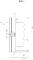
- FIG. 1 is a schematic front elevation view of an ink-jet printer 10 according to the present embodiment.
- the ink-jet printer 10 includes; a platen 11 that supports a medium 90 from a downside in a vertical direction represented with an arrow 10a; a rail 12 stretching in a horizontal direction represented with an arrow 10b, which is perpendicular to the direction represented with the arrow 10a; a carriage 13 that is supported by the rail 12 so as to be movable in the direction represented with the arrow 10b; and an ink-jet head 20, installed in the carriage 13, which discharges ink 20a toward the medium 90.
- the ink-jet printer 10 is provided with, for example, four ink-jet heads 20 that are individually able to discharge the ink 20a of yellow, magenta, cyan, and black.
- the ink 20a there can be used various kinds of ink.
- the ink 20a can be, for example, water-base ink, solvent ink, or ultraviolet (UV) ink as well.
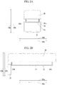
- FIG. 2A is a front elevation view of a neighborhood part of a nozzle surface 21 of the ink-jet head 20 in a state of being installed in the ink-jet printer 10.
- FIG. 2B is a side elevation view of the neighborhood part of the nozzle surface 21 of the ink-jet head 20 in a state shown in FIG. 2A .
- FIG. 3 is a bottom plan view of a part of the ink-jet head 20 in a state of being installed in the ink-jet printer 10.
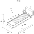
- FIG. 4 is an external perspective view of a part of the ink-jet head 20 in a state of being installed in the ink-jet printer 10, wherein the external perspective view being observed from a bottom side.
- FIG. 2A, FIG. 2B and FIG. 4 there is illustrated a blade 31 for wiping the nozzle surface 21, for reference.
- the blade 31 is not a constituent element of the ink-jet head 20.
- FIG. 3 and FIG. 4 show just an example, with respect to the number of rows of nozzles 21a as well as the number of holes that the each nozzles 21a has.
- the nozzle 21a is a row of nozzle holes in which a plurality of nozzle holes (for example, 200 or more) are arranged in a predetermined direction.
- a plurality of nozzle holes are arranged in the direction represented with the arrow 10c.
- a plurality of the nozzles 21a are arranged in a predetermined direction.
- the nozzles 21a are arranged in 8 rows in direction represented with the arrow 10c.
- the distance between the end of the row of nozzle holes included in each nozzle 21a and a convex wall part 22 is uniform, but is not limited thereto.
- the ink-jet head 20 includes the nozzle surface 21 in which a plurality of nozzles 21a to discharge the ink 20a (refer to FIG. 1 ) are formed, and a convex wall part 22 that surrounds the nozzle surface 21 in a state of protruding in a direction, represented with an arrow 20b, in which the ink 20a is discharged by the nozzles 21a.
- the nozzle surface 21 is coated with a material having a liquid-repellent property; in other words, a strong property of repelling the ink 20a; so as to have a strong liquid-repellent property. Meanwhile, in the nozzle surface 21, a location of the nozzles 21a does not have a liquid-repellent property; and accordingly, the ink 20a is more likely to stay in a vicinity of the nozzles 21a, in comparison to any other area excluding the vicinity of the nozzles 21a.
- a distance 23c between the nozzles 21a at an end in the direction represented with the arrow 10b and the convex wall part 22 is longer than the distance 23a, and shorter than the distance 23b.
- the blade 31 is scraped off by a corner 21b every time when the blade 31 contacts the corner 21b of an edge of the nozzle surface 21 at a time of wiping, to be described later.
- a provision of the convex wall part 22 is for a purpose of suppressing abrasion of the blade 31, by way of preventing the blade 31 from contacting the corner 21b of the edge of the nozzle surface 21 at a time of wiping.
- the ink-jet printer 10 is provided with a wiping device 30 for wiping the nozzle surface 21 by use of the blade 31, by way of moving the blade 31 (refer to FIG. 2 A, FIG. 2B ) in relation to the nozzle surface 21 (refer to FIG. 2 A, FIG. 2B ); wherein the wiping device 30 being located at a vicinity of an end of a traveling range of the ink-jet head 20 in the direction represented with the arrow 10b.
- the wiping device 30 includes the blade 31 having flexibility, and a blade driving device, which is not illustrated, for moving the blade 31 in relation to the nozzle surface 21.
- FIG. 5A is a front sectional view of a neighborhood part of the nozzle surface 21 of the ink-jet head 20, in a state of the nozzle surface 21 being wiped by the wiping device 30, and
- FIG. 5B is a side sectional view of the neighborhood part of the nozzle surface 21 of the ink-jet head 20 in a state shown in FIG. 5A .
- a direction represented with an arrow 30a wherein the direction being a direction of wiping by the wiping device 30, is almost the same as a stretching direction of a line connecting the nozzles 21a being closest to the convex wall part 22, among the plurality of nozzles 21a (refer to FIG. 3 ) formed in the nozzle surface 21, and a part of the convex wall part 22 being closest to the above-mentioned nozzles 21a.
- the direction represented with the arrow 30a is almost the same as a stretching direction of the rows of the nozzles 21a, the stretching direction being represented with the arrow 10c.
- the nozzles 21a being closest to the convex wall part 22, among the plurality of nozzles 21 a formed in the nozzle surface 21, are the nozzles 21a having the distance 23a from the convex wall part 22 (refer to FIG. 3 ).
- the convex wall part 22 includes two facing parts 22a that face each other in a direction represented with an arrow 30b, the direction being perpendicular to the direction represented with the arrow 30a.
- a length of the blade 31 in the direction represented with the arrow 30b is a length which makes it possible for the blade 31 to simultaneously contact tip parts 22b, in the direction represented with the arrow 20b, of the two facing parts 22a of the convex wall part 22, at a time of wiping operation by the wiping device 30. Then, the wiping device 30 wipes out the nozzle surface 21 by use of the blade 31, while making the blade 31 simultaneously contact the tip parts 22b of the two facing parts 22a.
- the wiping device 30 keeps a position of the blade 31 in relation to the nozzle surface 21, in the direction represented with the arrow 10a, around a location that prevents the blade 31 from contacting a specific range 21c adjacent to the facing parts 22a in the nozzle surface 21. Therefore, at the time of wiping out the nozzle surface 21 by use of the blade 31, there is a chance that the ink 20a remains at an area of the range 21c in the nozzle surface 21. Incidentally, the nozzles 21a are not formed at the area of the range 21c in the nozzle surface 21.
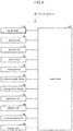
- FIG. 6 is a block diagram of the ink-jet printer 10.
- the ink-jet printer 10 includes; the ink-jet head 20; the wiping device 30; a medium transfer device 41 for transferring a medium 90 (refer to FIG. 1 ) in the direction represented with the arrow 10c (refer to FIG. 2 A, FIG. 2B ); a carriage drive device 42 for moving the carriage 13 (refer to FIG. 1 ) in the direction represented with the arrow 10b (refer to FIG.
- an operation unit 43 that is an input device including, for example, a button with which various operations are entered; a display unit 44 that is a display device such as a liquid crystal display (LCD) for displaying various information; a communication unit 45 that is a communication device for establishing communication with an external unit, either through a network, or directly by way of wired or wireless communication without using a network; a storage unit 46 that is a non-volatile memory device, such as a semi-conductor memory, a hard disc drive (HDD), and the like for storing various kinds of information, and a control unit 47 for controlling an entire section of the ink-jet printer 10.
- a display unit 44 that is a display device such as a liquid crystal display (LCD) for displaying various information
- a communication unit 45 that is a communication device for establishing communication with an external unit, either through a network, or directly by way of wired or wireless communication without using a network
- a storage unit 46 that is a non-volatile memory device, such as
- the control unit 47 for example, includes; a central processing unit (CPU); a read-only memory (ROM) for storing a program and various data; and a random access memory to be used as a workspace for the CPU.
- the CPU carries out the program stored in the ROM or the storage unit 46.
- the control unit 47 carries out printing operation for the medium 90, on the basis of the print data that is received by way of the communication unit 45. Namely, the control unit 47 carries out printing operation for the medium 90 in the direction represented with the arrow 10b, by way of transferring the carriage 13 in the direction represented with the arrow 10b by using the carriage drive device 42 and discharging the ink 20a toward the medium 90 by using the ink-jet head 20.
- the control unit 47 transfers the medium 90 in the direction represented with the arrow 10c, by using the medium transfer device 41, in such a way as to shift a printing position of the medium 90 in the direction represented with the arrow 10c.
- control unit 47 moves the carriage 13 in the direction represented with the arrow 10b by using the carriage drive device 42 at specific timing, so as to place the ink-jet head 20 to a position corresponding to the wiping device 30. Then, the control unit 47 wipes the nozzle surface 21 by using the blade 31, by way of moving the blade 31 by the wiping device 30 in the direction represented with the arrow 30a.
- the inventor of the present invention before adopting the direction represented with the arrow 30a as a direction of wiping the nozzle surface 21 by the wiping device 30, the inventor of the present invention also conducted a study with respect to the direction represented with the arrow 30b, as shown in FIG. 7A and FIG. 7B .
- FIG. 7A is a front sectional view of a neighborhood part of the nozzle surface 21 of the ink-jet head 20, in a state of the nozzle surface 21 being wiped by the wiping device 30, in the case where a configuration of the wiping device 30 is different from a configuration shown in FIG. 5A and FIG. 5B ; meanwhile, FIG. 7B is a side sectional view of the neighborhood part of the nozzle surface 21 of the ink-jet head 20 in a state shown in FIG. 7A .
- the wiping device 30 is provided with a blade 32, instead of the blade 31.
- the direction represented with the arrow 30b is almost the same as the direction represented with the arrow 10b, which is perpendicular to a stretching direction of the rows of the nozzles 21a, the stretching direction being represented with the arrow 10c.
- the convex wall part 22 includes two facing parts 22c that face each other in the direction represented with the arrow 30a.
- a length of the blade 32 in the direction represented with the arrow 30a is a length which makes it possible for the blade 32 to simultaneously contact tip parts 22d, in the direction represented with the arrow 20b, of the two facing parts 22c of the convex wall part 22, at a time of wiping operation by the wiping device 30. Then, the wiping device 30 wipes out the nozzle surface 21 by use of the blade 32, while making the blade 32 simultaneously contact the tip parts 22d of the two facing parts 22c.
- the wiping device 30 keeps a position of the blade 32 in relation to the nozzle surface 21, in the direction represented with the arrow 10a, around a location that prevents the blade 32 from contacting a specific range 21d adjacent to the facing parts 22c in the nozzle surface 21. Therefore, at the time of wiping out the nozzle surface 21 by use of the blade 32, there is a chance that the ink 20a remains at an area of the range 21d in the nozzle surface 21.
- FIG. 8 is a bottom plan view of a part of the ink-jet head 20, just after being wiped by the wiping device 30, in the case where a configuration of the wiping device 30 is as shown in FIG. 7A and FIG. 7B .
- the ink 20a remained in the vicinity of the nozzles 21a having the distance 23a as a distance from the convex wall part 22, as shown in FIG. 8 , on the nozzle surface 21 just after being wiped by the wiping device 30.
- the ink 20a remained in the vicinity of the nozzles 21a having the distance 23a as a distance from the convex wall part 22; it is considered that the ink 20a existing in the range 21d within the nozzle surface 21, which the blade 32 does not contact, was collected in the vicinity of the nozzles 21a having the distance 23a as the distance from the convex wall part 22, without being completely removed by the blade 32 because the distance 23a is too short, at a time of being removed by the blade 32 in a state of being repelled by way of the liquid-repellent property of the nozzle surface 21 so as to be collected.
- the inventor of the present invention obtained a finding, i.e., "the ink 20a is liable to remain and the amount of the remaining ink is much after wiping the nozzle surface 21 by a blade, at a vicinity of an end of the convex wall part 22 within the nozzle surface 21 in a direction perpendicular to a wiping direction, in comparison to a vicinity of an end of the convex wall part 22 within the nozzle surface 21 in the wiping direction.”
- a risk of an incidence of defective discharging of the ink 20a by the ink-jet head 20 is heightened, owing to presence of the ink 20a, remaining on the nozzle surface 21 after wiping, in the vicinity of the nozzles 21a. It is because the ink 20a remaining in the vicinity of the nozzles 21a moves onto the nozzles 21a so as to become a cause of defect, such as plugging the nozzles 21a, and the like. Therefore, it is preferable that the nozzles 21a are not located in the vicinity of an area where the ink 20a is liable to remain after wiping the nozzle surface 21 by use of the blade.
- wiping operation is carried out in the direction being almost the same as the stretching direction of the line connecting the specific nozzles 21a being closest to the convex wall part 22, among the plurality of nozzles 21a formed in the nozzle surface 21, and a part of the convex wall part 22 being closest to the above-mentioned nozzles 21a; that is to say, in the direction represented with the arrow 30a; in such a way that, being compared to a case of configuration in which wiping operation is carried out in a direction perpendicular to the above-described direction, i.e., in the direction represented with the arrow 30b, the ink 20a is unlikely to remain in the vicinity of the end of the convex wall part 22 so that the remaining amount of the ink 20a is less.
- the ink-jet printer 10 is able to suppress presence of the ink 20a remaining on the nozzle surface 21 after wiping operation, in the vicinity of the nozzles 21a; and as a result, an incidence of defective discharging of the ink 20a by the ink-jet head 20 can be reduced.
- the ink 20a existing on the nozzle surface 21 is removed by the blade in a state of being repelled by way of the liquid-repellent property of the nozzle surface 21 so as to be collected.
- a hole of the nozzles 21a of the nozzle surface 21 is inevitably filled with the ink 20a, while the hole does not have a liquid-repellent property, so that the ink 20a is liable to remain after wiping operation by a blade, around the hole of the nozzles 21a and its vicinity, in comparison to any area other than the vicinity of the hole of the nozzles 21a.
- the nozzle surface 21 is wiped by the blade 31 in the direction being almost the same as the stretching direction of the line connecting the nozzles 21a being closest to the convex wall part 22, among the plurality of nozzles 21a formed in the nozzle surface 21, and a part of the convex wall part 22 being closest to the above-mentioned nozzles 21a; that is to say, in the direction represented with the arrow 30a; in such a way that, being compared to the case where the nozzle surface 21 is wiped by the blade 32 in the direction represented with the arrow 30b, perpendicular to the direction represented with the arrow 30a, the ink 20a is unlikely to remain in the vicinity of the nozzles 21a in the neighborhood of the convex wall part 22 in the nozzle surface 21, and therefore, the amount of the ink remaining can be made less.
- the amount of the ink remaining can be made less in the vicinity of the end of the convex wall part 22 after wiping the nozzle surface 21 by use of the blade 31, so that it is possible to suppress a defective incidence, such as the ink 20a moving onto the nozzles 21a and plugging the nozzles 21a, and the like; wherein the ink 20a remaining in the vicinity of the end of the convex wall part 22.
- the ink-jet printer 10 can reduce the amount of the ink 20a remaining on the nozzle surface 21 having been wiped; and as a result, an incidence of defective discharging of the ink 20a by the ink-jet head 20 can be reduced.
- the ink-jet printer 10 does not have the blade 31 contact an area of the range 21c in the vicinity of the facing parts 22a in the nozzle surface 21; and therefore, being compared to a case of configuration in which the blade 31 contacts the area of the range 21c in the vicinity of the facing parts 22a in the nozzle surface 21 at the time of wiping the nozzle surface 21 by use of the blade 31, a blade 31 having low flexibility can be employed; and as a result, durability of the blade 31 can be improved.
- the ink 20a is liable to remain just after wiping the nozzle surface 21 by the blade 31.
- the nozzles 21a are not formed in the area of the range 21c, which the blade 31 does not contact at the time of wiping, in the nozzle surface 21; and therefore, the amount of the ink 20a remaining in the vicinity of the nozzles 21a in the neighborhood of the convex wall part 22, in the nozzle surface 21 having been wiped, can be reduced; and as a result, an incidence of defective discharging of the ink 20a by the ink-jet head 20 can be reduced.
- the stretching direction of the line connecting the specific nozzles 21a being closest to the convex wall part 22, among the plurality of nozzles 21a formed in the nozzle surface 21, and a part of the convex wall part 22 being closest to the above-mentioned nozzles 21a is almost the same as the stretching direction, being represented with the arrow 10c, of the rows of the nozzles 21a.
- the stretching direction of the line connecting the specific nozzles 21a being closest to the convex wall part 22, among the plurality of nozzles 21a formed in the nozzle surface 21, and a part of the convex wall part 22 being closest to the above-mentioned nozzles 21a may be almost the same as the direction represented with the arrow 10b that is perpendicular to the stretching direction, being represented with the arrow 10c, of the rows of the nozzles 21a.
Landscapes
- Ink Jet (AREA)
Applications Claiming Priority (1)
| Application Number | Priority Date | Filing Date | Title |
|---|---|---|---|
| JP2018076086A JP7023774B2 (ja) | 2018-04-11 | 2018-04-11 | インクジェットプリンター |
Publications (2)
| Publication Number | Publication Date |
|---|---|
| EP3552827A1 true EP3552827A1 (de) | 2019-10-16 |
| EP3552827B1 EP3552827B1 (de) | 2021-05-26 |
Family
ID=66101889
Family Applications (1)
| Application Number | Title | Priority Date | Filing Date |
|---|---|---|---|
| EP19167487.8A Active EP3552827B1 (de) | 2018-04-11 | 2019-04-05 | Tintenstrahldrucker |
Country Status (3)
| Country | Link |
|---|---|
| US (1) | US10875311B2 (de) |
| EP (1) | EP3552827B1 (de) |
| JP (1) | JP7023774B2 (de) |
Citations (6)
| Publication number | Priority date | Publication date | Assignee | Title |
|---|---|---|---|---|
| JPH07195686A (ja) * | 1993-12-28 | 1995-08-01 | Nec Corp | インクジェットプリントヘッド |
| US20020134305A1 (en) * | 2001-03-21 | 2002-09-26 | Olympus Optical Co., Ltd. | Ink jet printer |
| JP2012166374A (ja) | 2011-02-10 | 2012-09-06 | Canon Inc | インクジェット記録装置 |
| US20130208047A1 (en) * | 2012-02-10 | 2013-08-15 | Ricoh Company, Ltd. | Liquid discharge head and image forming apparatus |
| US20140028757A1 (en) * | 2012-07-27 | 2014-01-30 | Canon Kabushiki Kaisha | Liquid ejection head and method for manufacturing liquid ejection head |
| WO2014129010A1 (ja) * | 2013-02-19 | 2014-08-28 | 株式会社セイコーアイ・インフォテック | インクジェットプリンター |
Family Cites Families (5)
| Publication number | Priority date | Publication date | Assignee | Title |
|---|---|---|---|---|
| JPH04235054A (ja) * | 1991-01-09 | 1992-08-24 | Seiko Epson Corp | インクジェット記録装置 |
| US6454388B1 (en) * | 1999-12-29 | 2002-09-24 | Hewlett-Packard Company | Sequestering residual ink on an ink-jet print cartridge |
| KR100727971B1 (ko) * | 2005-09-01 | 2007-06-14 | 삼성전자주식회사 | 와이퍼, 클리닝 장치, 및 이를 구비하는 잉크젯화상형성장치 |
| JP6111479B2 (ja) * | 2012-10-31 | 2017-04-12 | 株式会社ミマキエンジニアリング | インクジェット記録装置 |
| JP6315177B2 (ja) * | 2014-03-03 | 2018-04-25 | セイコーエプソン株式会社 | 液体噴射装置 |
-
2018
- 2018-04-11 JP JP2018076086A patent/JP7023774B2/ja active Active
-
2019
- 2019-04-05 EP EP19167487.8A patent/EP3552827B1/de active Active
- 2019-04-10 US US16/379,804 patent/US10875311B2/en active Active
Patent Citations (6)
| Publication number | Priority date | Publication date | Assignee | Title |
|---|---|---|---|---|
| JPH07195686A (ja) * | 1993-12-28 | 1995-08-01 | Nec Corp | インクジェットプリントヘッド |
| US20020134305A1 (en) * | 2001-03-21 | 2002-09-26 | Olympus Optical Co., Ltd. | Ink jet printer |
| JP2012166374A (ja) | 2011-02-10 | 2012-09-06 | Canon Inc | インクジェット記録装置 |
| US20130208047A1 (en) * | 2012-02-10 | 2013-08-15 | Ricoh Company, Ltd. | Liquid discharge head and image forming apparatus |
| US20140028757A1 (en) * | 2012-07-27 | 2014-01-30 | Canon Kabushiki Kaisha | Liquid ejection head and method for manufacturing liquid ejection head |
| WO2014129010A1 (ja) * | 2013-02-19 | 2014-08-28 | 株式会社セイコーアイ・インフォテック | インクジェットプリンター |
Also Published As
| Publication number | Publication date |
|---|---|
| JP2019181817A (ja) | 2019-10-24 |
| EP3552827B1 (de) | 2021-05-26 |
| US20190315127A1 (en) | 2019-10-17 |
| JP7023774B2 (ja) | 2022-02-22 |
| US10875311B2 (en) | 2020-12-29 |
Similar Documents
| Publication | Publication Date | Title |
|---|---|---|
| US10618288B2 (en) | Shroud for a printhead assembly | |
| US8845053B2 (en) | Inkjet printing device and inkjet printing method | |
| JP2006212863A (ja) | インクジェット記録装置、及びインクジェット記録ヘッドのノズル面の清掃方法 | |
| JP6244797B2 (ja) | 液滴吐出装置及び液滴吐出方法 | |
| US7909431B2 (en) | Image recording apparatus | |
| JP2002019133A (ja) | インクジェットプリンタ用ワイパー | |
| US10071555B2 (en) | Liquid ejection apparatus | |
| KR100522936B1 (ko) | 잉크젯 프린터의 메인트넌스 방법 | |
| US10875311B2 (en) | Ink-jet printer for suppressing ink remaining | |
| US10391773B2 (en) | Liquid ejecting apparatus | |
| JP2021030482A (ja) | インクジェット記録装置 | |
| JP7131229B2 (ja) | 液体吐出装置 | |
| JP2021120207A (ja) | 液体吐出装置及びシステム | |
| EP2979875B1 (de) | Tintenstrahlbilderzeugungsvorrichtung und reinigungsverfahren für die tintenstrahlbilderzeugungsvorrichtung | |
| JP7268370B2 (ja) | 記録装置および記録方法 | |
| US8573734B2 (en) | Movable spittoon platform | |
| CN111619226B (zh) | 喷墨记录装置以及维护方法 | |
| JP2009248370A (ja) | 記録装置 | |
| JP2017154276A (ja) | 液体吐出装置 | |
| JP2017065144A (ja) | 液体噴射装置及び液体噴射ヘッドのクリーニング方法 | |
| JP7613224B2 (ja) | 記録ヘッド及びインクジェット記録装置 | |
| JP6852764B2 (ja) | 記録ヘッド及びそれを備えたインクジェット記録装置 | |
| JP2010228118A (ja) | 流体噴射装置のメンテナンス方法及び流体噴射装置 | |
| KR20170133799A (ko) | 액적 토출 장치 | |
| JP5011772B2 (ja) | 機能液滴吐出方法およびカラーフィルタの製造方法 |
Legal Events
| Date | Code | Title | Description |
|---|---|---|---|
| PUAI | Public reference made under article 153(3) epc to a published international application that has entered the european phase |
Free format text: ORIGINAL CODE: 0009012 |
|
| STAA | Information on the status of an ep patent application or granted ep patent |
Free format text: STATUS: THE APPLICATION HAS BEEN PUBLISHED |
|
| AK | Designated contracting states |
Kind code of ref document: A1 Designated state(s): AL AT BE BG CH CY CZ DE DK EE ES FI FR GB GR HR HU IE IS IT LI LT LU LV MC MK MT NL NO PL PT RO RS SE SI SK SM TR |
|
| AX | Request for extension of the european patent |
Extension state: BA ME |
|
| STAA | Information on the status of an ep patent application or granted ep patent |
Free format text: STATUS: REQUEST FOR EXAMINATION WAS MADE |
|
| 17P | Request for examination filed |
Effective date: 20200416 |
|
| RBV | Designated contracting states (corrected) |
Designated state(s): AL AT BE BG CH CY CZ DE DK EE ES FI FR GB GR HR HU IE IS IT LI LT LU LV MC MK MT NL NO PL PT RO RS SE SI SK SM TR |
|
| REG | Reference to a national code |
Ref country code: DE Ref legal event code: R079 Ref document number: 602019004804 Country of ref document: DE Free format text: PREVIOUS MAIN CLASS: B41J0002165000 Ipc: B41J0002150000 |
|
| GRAP | Despatch of communication of intention to grant a patent |
Free format text: ORIGINAL CODE: EPIDOSNIGR1 |
|
| STAA | Information on the status of an ep patent application or granted ep patent |
Free format text: STATUS: GRANT OF PATENT IS INTENDED |
|
| RIC1 | Information provided on ipc code assigned before grant |
Ipc: B41J 2/15 20060101AFI20201123BHEP Ipc: B41J 2/14 20060101ALI20201123BHEP Ipc: B41J 2/165 20060101ALI20201123BHEP |
|
| INTG | Intention to grant announced |
Effective date: 20201216 |
|
| GRAS | Grant fee paid |
Free format text: ORIGINAL CODE: EPIDOSNIGR3 |
|
| GRAA | (expected) grant |
Free format text: ORIGINAL CODE: 0009210 |
|
| STAA | Information on the status of an ep patent application or granted ep patent |
Free format text: STATUS: THE PATENT HAS BEEN GRANTED |
|
| AK | Designated contracting states |
Kind code of ref document: B1 Designated state(s): AL AT BE BG CH CY CZ DE DK EE ES FI FR GB GR HR HU IE IS IT LI LT LU LV MC MK MT NL NO PL PT RO RS SE SI SK SM TR |
|
| REG | Reference to a national code |
Ref country code: GB Ref legal event code: FG4D |
|
| REG | Reference to a national code |
Ref country code: CH Ref legal event code: EP |
|
| REG | Reference to a national code |
Ref country code: DE Ref legal event code: R096 Ref document number: 602019004804 Country of ref document: DE |
|
| REG | Reference to a national code |
Ref country code: AT Ref legal event code: REF Ref document number: 1395814 Country of ref document: AT Kind code of ref document: T Effective date: 20210615 |
|
| REG | Reference to a national code |
Ref country code: IE Ref legal event code: FG4D |
|
| REG | Reference to a national code |
Ref country code: LT Ref legal event code: MG9D |
|
| REG | Reference to a national code |
Ref country code: AT Ref legal event code: MK05 Ref document number: 1395814 Country of ref document: AT Kind code of ref document: T Effective date: 20210526 |
|
| PG25 | Lapsed in a contracting state [announced via postgrant information from national office to epo] |
Ref country code: HR Free format text: LAPSE BECAUSE OF FAILURE TO SUBMIT A TRANSLATION OF THE DESCRIPTION OR TO PAY THE FEE WITHIN THE PRESCRIBED TIME-LIMIT Effective date: 20210526 Ref country code: LT Free format text: LAPSE BECAUSE OF FAILURE TO SUBMIT A TRANSLATION OF THE DESCRIPTION OR TO PAY THE FEE WITHIN THE PRESCRIBED TIME-LIMIT Effective date: 20210526 Ref country code: FI Free format text: LAPSE BECAUSE OF FAILURE TO SUBMIT A TRANSLATION OF THE DESCRIPTION OR TO PAY THE FEE WITHIN THE PRESCRIBED TIME-LIMIT Effective date: 20210526 Ref country code: BG Free format text: LAPSE BECAUSE OF FAILURE TO SUBMIT A TRANSLATION OF THE DESCRIPTION OR TO PAY THE FEE WITHIN THE PRESCRIBED TIME-LIMIT Effective date: 20210826 Ref country code: AT Free format text: LAPSE BECAUSE OF FAILURE TO SUBMIT A TRANSLATION OF THE DESCRIPTION OR TO PAY THE FEE WITHIN THE PRESCRIBED TIME-LIMIT Effective date: 20210526 |
|
| REG | Reference to a national code |
Ref country code: NL Ref legal event code: MP Effective date: 20210526 |
|
| PG25 | Lapsed in a contracting state [announced via postgrant information from national office to epo] |
Ref country code: NO Free format text: LAPSE BECAUSE OF FAILURE TO SUBMIT A TRANSLATION OF THE DESCRIPTION OR TO PAY THE FEE WITHIN THE PRESCRIBED TIME-LIMIT Effective date: 20210826 Ref country code: PL Free format text: LAPSE BECAUSE OF FAILURE TO SUBMIT A TRANSLATION OF THE DESCRIPTION OR TO PAY THE FEE WITHIN THE PRESCRIBED TIME-LIMIT Effective date: 20210526 Ref country code: LV Free format text: LAPSE BECAUSE OF FAILURE TO SUBMIT A TRANSLATION OF THE DESCRIPTION OR TO PAY THE FEE WITHIN THE PRESCRIBED TIME-LIMIT Effective date: 20210526 Ref country code: PT Free format text: LAPSE BECAUSE OF FAILURE TO SUBMIT A TRANSLATION OF THE DESCRIPTION OR TO PAY THE FEE WITHIN THE PRESCRIBED TIME-LIMIT Effective date: 20210927 Ref country code: RS Free format text: LAPSE BECAUSE OF FAILURE TO SUBMIT A TRANSLATION OF THE DESCRIPTION OR TO PAY THE FEE WITHIN THE PRESCRIBED TIME-LIMIT Effective date: 20210526 Ref country code: SE Free format text: LAPSE BECAUSE OF FAILURE TO SUBMIT A TRANSLATION OF THE DESCRIPTION OR TO PAY THE FEE WITHIN THE PRESCRIBED TIME-LIMIT Effective date: 20210526 Ref country code: GR Free format text: LAPSE BECAUSE OF FAILURE TO SUBMIT A TRANSLATION OF THE DESCRIPTION OR TO PAY THE FEE WITHIN THE PRESCRIBED TIME-LIMIT Effective date: 20210827 Ref country code: IS Free format text: LAPSE BECAUSE OF FAILURE TO SUBMIT A TRANSLATION OF THE DESCRIPTION OR TO PAY THE FEE WITHIN THE PRESCRIBED TIME-LIMIT Effective date: 20210926 |
|
| PG25 | Lapsed in a contracting state [announced via postgrant information from national office to epo] |
Ref country code: NL Free format text: LAPSE BECAUSE OF FAILURE TO SUBMIT A TRANSLATION OF THE DESCRIPTION OR TO PAY THE FEE WITHIN THE PRESCRIBED TIME-LIMIT Effective date: 20210526 |
|
| PG25 | Lapsed in a contracting state [announced via postgrant information from national office to epo] |
Ref country code: SK Free format text: LAPSE BECAUSE OF FAILURE TO SUBMIT A TRANSLATION OF THE DESCRIPTION OR TO PAY THE FEE WITHIN THE PRESCRIBED TIME-LIMIT Effective date: 20210526 Ref country code: ES Free format text: LAPSE BECAUSE OF FAILURE TO SUBMIT A TRANSLATION OF THE DESCRIPTION OR TO PAY THE FEE WITHIN THE PRESCRIBED TIME-LIMIT Effective date: 20210526 Ref country code: EE Free format text: LAPSE BECAUSE OF FAILURE TO SUBMIT A TRANSLATION OF THE DESCRIPTION OR TO PAY THE FEE WITHIN THE PRESCRIBED TIME-LIMIT Effective date: 20210526 Ref country code: SM Free format text: LAPSE BECAUSE OF FAILURE TO SUBMIT A TRANSLATION OF THE DESCRIPTION OR TO PAY THE FEE WITHIN THE PRESCRIBED TIME-LIMIT Effective date: 20210526 Ref country code: RO Free format text: LAPSE BECAUSE OF FAILURE TO SUBMIT A TRANSLATION OF THE DESCRIPTION OR TO PAY THE FEE WITHIN THE PRESCRIBED TIME-LIMIT Effective date: 20210526 Ref country code: DK Free format text: LAPSE BECAUSE OF FAILURE TO SUBMIT A TRANSLATION OF THE DESCRIPTION OR TO PAY THE FEE WITHIN THE PRESCRIBED TIME-LIMIT Effective date: 20210526 Ref country code: CZ Free format text: LAPSE BECAUSE OF FAILURE TO SUBMIT A TRANSLATION OF THE DESCRIPTION OR TO PAY THE FEE WITHIN THE PRESCRIBED TIME-LIMIT Effective date: 20210526 |
|
| REG | Reference to a national code |
Ref country code: DE Ref legal event code: R097 Ref document number: 602019004804 Country of ref document: DE |
|
| PLBE | No opposition filed within time limit |
Free format text: ORIGINAL CODE: 0009261 |
|
| STAA | Information on the status of an ep patent application or granted ep patent |
Free format text: STATUS: NO OPPOSITION FILED WITHIN TIME LIMIT |
|
| 26N | No opposition filed |
Effective date: 20220301 |
|
| PG25 | Lapsed in a contracting state [announced via postgrant information from national office to epo] |
Ref country code: IS Free format text: LAPSE BECAUSE OF FAILURE TO SUBMIT A TRANSLATION OF THE DESCRIPTION OR TO PAY THE FEE WITHIN THE PRESCRIBED TIME-LIMIT Effective date: 20210926 Ref country code: AL Free format text: LAPSE BECAUSE OF FAILURE TO SUBMIT A TRANSLATION OF THE DESCRIPTION OR TO PAY THE FEE WITHIN THE PRESCRIBED TIME-LIMIT Effective date: 20210526 |
|
| PG25 | Lapsed in a contracting state [announced via postgrant information from national office to epo] |
Ref country code: IT Free format text: LAPSE BECAUSE OF FAILURE TO SUBMIT A TRANSLATION OF THE DESCRIPTION OR TO PAY THE FEE WITHIN THE PRESCRIBED TIME-LIMIT Effective date: 20210526 |
|
| REG | Reference to a national code |
Ref country code: CH Ref legal event code: PL |
|
| REG | Reference to a national code |
Ref country code: BE Ref legal event code: MM Effective date: 20220430 |
|
| PG25 | Lapsed in a contracting state [announced via postgrant information from national office to epo] |
Ref country code: MC Free format text: LAPSE BECAUSE OF FAILURE TO SUBMIT A TRANSLATION OF THE DESCRIPTION OR TO PAY THE FEE WITHIN THE PRESCRIBED TIME-LIMIT Effective date: 20210526 Ref country code: LU Free format text: LAPSE BECAUSE OF NON-PAYMENT OF DUE FEES Effective date: 20220405 Ref country code: LI Free format text: LAPSE BECAUSE OF NON-PAYMENT OF DUE FEES Effective date: 20220430 Ref country code: CH Free format text: LAPSE BECAUSE OF NON-PAYMENT OF DUE FEES Effective date: 20220430 |
|
| PG25 | Lapsed in a contracting state [announced via postgrant information from national office to epo] |
Ref country code: BE Free format text: LAPSE BECAUSE OF NON-PAYMENT OF DUE FEES Effective date: 20220430 |
|
| PG25 | Lapsed in a contracting state [announced via postgrant information from national office to epo] |
Ref country code: IE Free format text: LAPSE BECAUSE OF NON-PAYMENT OF DUE FEES Effective date: 20220405 |
|
| GBPC | Gb: european patent ceased through non-payment of renewal fee |
Effective date: 20230405 |
|
| PG25 | Lapsed in a contracting state [announced via postgrant information from national office to epo] |
Ref country code: GB Free format text: LAPSE BECAUSE OF NON-PAYMENT OF DUE FEES Effective date: 20230405 |
|
| PG25 | Lapsed in a contracting state [announced via postgrant information from national office to epo] |
Ref country code: GB Free format text: LAPSE BECAUSE OF NON-PAYMENT OF DUE FEES Effective date: 20230405 |
|
| PG25 | Lapsed in a contracting state [announced via postgrant information from national office to epo] |
Ref country code: HU Free format text: LAPSE BECAUSE OF FAILURE TO SUBMIT A TRANSLATION OF THE DESCRIPTION OR TO PAY THE FEE WITHIN THE PRESCRIBED TIME-LIMIT; INVALID AB INITIO Effective date: 20190405 |
|
| PG25 | Lapsed in a contracting state [announced via postgrant information from national office to epo] |
Ref country code: MK Free format text: LAPSE BECAUSE OF FAILURE TO SUBMIT A TRANSLATION OF THE DESCRIPTION OR TO PAY THE FEE WITHIN THE PRESCRIBED TIME-LIMIT Effective date: 20210526 Ref country code: CY Free format text: LAPSE BECAUSE OF FAILURE TO SUBMIT A TRANSLATION OF THE DESCRIPTION OR TO PAY THE FEE WITHIN THE PRESCRIBED TIME-LIMIT Effective date: 20210526 |
|
| PG25 | Lapsed in a contracting state [announced via postgrant information from national office to epo] |
Ref country code: MT Free format text: LAPSE BECAUSE OF FAILURE TO SUBMIT A TRANSLATION OF THE DESCRIPTION OR TO PAY THE FEE WITHIN THE PRESCRIBED TIME-LIMIT Effective date: 20210526 |
|
| PGFP | Annual fee paid to national office [announced via postgrant information from national office to epo] |
Ref country code: FR Payment date: 20250310 Year of fee payment: 7 |
|
| PGFP | Annual fee paid to national office [announced via postgrant information from national office to epo] |
Ref country code: DE Payment date: 20250305 Year of fee payment: 7 |
|
| PG25 | Lapsed in a contracting state [announced via postgrant information from national office to epo] |
Ref country code: TR Free format text: LAPSE BECAUSE OF FAILURE TO SUBMIT A TRANSLATION OF THE DESCRIPTION OR TO PAY THE FEE WITHIN THE PRESCRIBED TIME-LIMIT Effective date: 20210526 |