EP3552788A1 - Mischgerät für feuchte oder trockene materialien, insbesondere komponenten für die betonherstellung - Google Patents
Mischgerät für feuchte oder trockene materialien, insbesondere komponenten für die betonherstellung Download PDFInfo
- Publication number
- EP3552788A1 EP3552788A1 EP19165308.8A EP19165308A EP3552788A1 EP 3552788 A1 EP3552788 A1 EP 3552788A1 EP 19165308 A EP19165308 A EP 19165308A EP 3552788 A1 EP3552788 A1 EP 3552788A1
- Authority
- EP
- European Patent Office
- Prior art keywords
- mixing
- train
- diameter
- kneading
- axis
- Prior art date
- Legal status (The legal status is an assumption and is not a legal conclusion. Google has not performed a legal analysis and makes no representation as to the accuracy of the status listed.)
- Granted
Links
Images


Classifications
-
- B—PERFORMING OPERATIONS; TRANSPORTING
- B28—WORKING CEMENT, CLAY, OR STONE
- B28C—PREPARING CLAY; PRODUCING MIXTURES CONTAINING CLAY OR CEMENTITIOUS MATERIAL, e.g. PLASTER
- B28C5/00—Apparatus or methods for producing mixtures of cement with other substances, e.g. slurries, mortars, porous or fibrous compositions
- B28C5/08—Apparatus or methods for producing mixtures of cement with other substances, e.g. slurries, mortars, porous or fibrous compositions using driven mechanical means affecting the mixing
- B28C5/10—Mixing in containers not actuated to effect the mixing
- B28C5/12—Mixing in containers not actuated to effect the mixing with stirrers sweeping through the materials, e.g. with incorporated feeding or discharging means or with oscillating stirrers
- B28C5/16—Mixing in containers not actuated to effect the mixing with stirrers sweeping through the materials, e.g. with incorporated feeding or discharging means or with oscillating stirrers the stirrers having motion about a vertical or steeply inclined axis
- B28C5/166—Pan-type mixers
- B28C5/168—Pan-type mixers with stirrers having planetary motion
-
- B—PERFORMING OPERATIONS; TRANSPORTING
- B01—PHYSICAL OR CHEMICAL PROCESSES OR APPARATUS IN GENERAL
- B01F—MIXING, e.g. DISSOLVING, EMULSIFYING OR DISPERSING
- B01F27/00—Mixers with rotary stirring devices in fixed receptacles; Kneaders
- B01F27/80—Mixers with rotary stirring devices in fixed receptacles; Kneaders with stirrers rotating about a substantially vertical axis
- B01F27/95—Mixers with rotary stirring devices in fixed receptacles; Kneaders with stirrers rotating about a substantially vertical axis with stirrers having planetary motion, i.e. rotating about their own axis and about a sun axis
-
- B—PERFORMING OPERATIONS; TRANSPORTING
- B28—WORKING CEMENT, CLAY, OR STONE
- B28C—PREPARING CLAY; PRODUCING MIXTURES CONTAINING CLAY OR CEMENTITIOUS MATERIAL, e.g. PLASTER
- B28C5/00—Apparatus or methods for producing mixtures of cement with other substances, e.g. slurries, mortars, porous or fibrous compositions
- B28C5/08—Apparatus or methods for producing mixtures of cement with other substances, e.g. slurries, mortars, porous or fibrous compositions using driven mechanical means affecting the mixing
- B28C5/0806—Details; Accessories
- B28C5/0818—Charging or discharging gates or chutes; Sealing means
Definitions
- the present invention relates to an apparatus for mixing wet or dry materials, in particular components for the manufacture of concrete.
- the field of the invention is that of apparatus for mixing wet or dry materials, and in particular the various components used in the manufacture of concrete, and more particularly on the concrete manufacturing sites, known as mills. concrete.
- such an apparatus generally comprises a tank, whose size can reach several m3. Said tank receives the various materials to be kneaded, such as the various components of the concrete, such as cement, water, sand, aggregates and various additives, which are mixed and kneaded so as to form a homogeneous pasty mixture which can then be used on any type of site.
- various materials to be kneaded such as the various components of the concrete, such as cement, water, sand, aggregates and various additives, which are mixed and kneaded so as to form a homogeneous pasty mixture which can then be used on any type of site.
- Mixing blades driven in rotation relative to the tank are used to perform the mixing and mixing of the raw materials of the concrete.
- the invention relates more particularly to the field of kneaders with fixed bowl and epicyclic gear for which the kneading blades are driven along planetary trajectories.
- document is known FR2 527 939 A a mixing apparatus with a fixed vessel comprising a fixed vessel into which the various components to be kneaded are introduced, a kneading train comprising blades driven in an epicyclic movement by a motor unit.
- the drive device of the kneading train comprises a fixed drive member, driving a turntable via a ring integral with the outer diameter of the plate.
- the turntable serves as a support for the kneading train, said kneading train being articulated in rotation on the plate.
- the kneading train has on its drive shaft, a pinion receiver which meshes around a fixed ring to be rotated relative to the turntable.
- the turntable and the fixed ring are coaxial and leave in their center a large central clearance.
- a kneading train generally comprises at least one arm, at each end of which is fixed a blade, said arm extending perpendicular to the drive shaft of the kneading train, and in a conventional manner centered on said shaft of training.
- the drive shafts of the various mixing trains are designed to be rotated by the same drive ring, and conventionally by means of identical pinions.
- these different drive shafts will have angular drive speeds with respect to the identical trough, the angular rotational speed of each kneading train relative to its drive shaft depending on the ratio between the number of teeth. of its receiving pinion and that of the fixed wheel.
- the kneading blades attached to the two ends of the arm of each kneading train will have a linear speed, which will vary continuously, which makes it possible to carry out the kneading by differential stretching of the mixture of different materials.
- the kneading trains are rotated about their axis, in the same direction of rotation as the turntable, which maximizes the maximum linear speed of said blade.
- the linear velocity of each blade must be such that it does not exceed a certain value, so as not to cause a degradation of the efficiency of the mixture, by segregation and projection, as well as accelerated wear, and that not be less than a certain value, which would also be detrimental to its effectiveness.
- the dimension of the arms supporting the mixing blades must be such that at least the blades of a kneading train pass through the center of the tank and the peripheral zone of the tank, which receives the majority of the mixture, without the blades of the different kneading trains come to collide, during operation of said kneading apparatus.
- Such a mixer 1 ' is shown schematically on the figure 1 of this application.
- a single mixing train 3 ' has its blades 34' passing through the center A 'of the tank 2' and that the other mixing trains 4 'have their blades 44' passing at the periphery 21 'of the tank 2'.
- the shaft drive 41 'mixing trains 4' having blades 34 ', 44' not passing through the center A 'of the tank 2' is offset relative to the circular ring 6 'on which the drive pinion 32 'mounted on the drive shaft 31' of the kneading train 3 'whose blades 34' pass through the center A 'of tank 2'.
- two gears 45 ', 46' are interposed between said circular ring 6 'and said drive gear 42' of the mixing trains 4 'offset, not passing through the center A' of the tank 2 '.
- the blades 44 of the remote mixing trains 4 ' travel in a circular path T4' of diameter D4 ', less than the diameter D3' of the circular path T3 'traversed by the blades 34 of the first kneading train 3.
- the driving angular velocities of the different mixing trains 3 ', 4' remain identical if their driving pinions 32 ', 42' are so, which is the case in the device described in the document WO 9,511,120 A .
- the maximum linear speed of the blades 34 of the first mixing train 3 is 3.71 m / s
- the maximum linear speed of the blades 44 of each of the second mixing trains 4 is 3.59 m / s.
- the average maximum linear speed of the blades is also 3.63 m / s.
- said ring being provided to be optionally arranged around a supply line of the tank, it will be necessary to also reduce the diameter of said duct, which can be problematic to ensure the supply of the tank of optimal way.
- the maximum linear speed of the blades of kneading trains in remote position is limited by this design.
- Such a limitation affects the overall mixing performance, in particular when the mixing trains in the offset position are in number (i.e. two, three) and that their kneading action thus becomes preponderant.
- the invention proposes to overcome these disadvantages by providing an apparatus for mixing wet or dry materials, in particular components for the manufacture of concrete to ensure a homogeneous mixture of materials, simple design and low cost, and especially in the case where said kneading apparatus is provided for mixing a large amount of materials.
- the invention also makes it possible to use a supply duct centered on the axis of the fixed vessel, of such dimensions as to allow an optimal supply of said vessel.
- the pinion fixed on the drive shaft of the first kneading train meshes with the first ring gear
- the pinion fixed on the drive shaft of the at least one second kneading gear meshes with the second circular crown
- the at least one second kneading train 4 can be in a position remote from the first kneading train 3, without using intermediate gears, which simplifies the design of said apparatus 1 and reduces its cost.
- the driving angular speed of the drive shaft 41 of the at least one second kneading unit 4 will be greater than the angular drive speed of the drive shaft 31 of the first mixing train 3, while their respective pinions 32, 42 can remain identical.
- the linear speeds at each of the at least one blade 34, 44 of each of the mixing trains 3, 4 are such that the kneading of the materials is optimal so as to obtain a homogeneous concrete.
- the maximum linear speeds of the blades 34, 44 may be substantially identical, or similar, which allows optimal mixing of the materials in the tank 2.
- the maximum linear speed of the at least one blade 44 of each second kneading unit 4 may be greater than the maximum linear speed of the at least one blade of the first mixing train 3, which is particularly advantageous in that the kneading action of said second kneading trains is predominant.
- the maximum linear speed of each blade 44 of the second mixing trains is about 3.8 m / s while the maximum linear speed of the blades 34 of the first mixing train 3 is about 3.5 m / s .
- the average maximum linear velocity is then 3.72 m / s.
- the rotary plate 5 is rotated by means of a plurality of geared motors 51 distributed regularly around the turntable, each comprising for example a pinion 52 mounted on their drive shaft, said pinion 52 meshing with a circular ring gear 53 attached to the turntable 5.
- a plurality of geared motors 51 distributed regularly around the turntable, each comprising for example a pinion 52 mounted on their drive shaft, said pinion 52 meshing with a circular ring gear 53 attached to the turntable 5.
- all or part of the blades 34, 44 of the mixing trains 3, 4 can be replaced by other rotating elements involved in the mixing of the concrete, such as for example a concrete propeller or still a quick dispersive tool 48, also known as Wirbler in English or Wirbel in German.
- such a rapid dispersing effect tool 48 may advantageously be positioned at a second kneading train 4, dimensioned so as to end up being propelled at a linear speed of between 5 and 10 m / s, depending on the size of the particles present. in the tank 2 and the viscosity of the materials.
- Such a tool with a dispersive effect 48 has an effect of impact grinding on the materials present in the tank 2, which combined with the differential stretching carried out by the blades 34, 44 of the kneading trains 3, 4 makes it possible to optimize the mixing of materials in the tank 2.
- this rapid dispersive effect tool 48 at a second mixing train 4 whose pinion 42 meshes with the second circular ring 7 advantageously makes it possible to act on the particles of the materials in the tank 2 near the periphery 22 of said tank 2, which will be trapped against the periphery 22 of the tank 2 by such a rapid dispersive effect tool 48, which can break the nodules of fine particles of materials.
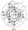
- the mixing apparatus 1 comprises a supply duct 21 disposed above the tank 2, centered on the axis A of the tank 2.
- the first ring gear 6 and the second ring gear 7 are positioned around the feed duct 21 and their respective diameters D6, D7 are strictly greater than the diameter D21 of said supply duct 21, so as not to obstruct the passage to through the supply duct 21, which can thus maintain a dimension such as to allow optimum supply of said fixed vessel 2.
- the rotary plate 5 may comprise a central bore 51, of diameter strictly greater than the diameter D21 of the supply duct.
- the first kneading train 3 comprises an arm 33 of length L33, arranged perpendicularly to the drive shaft 32, centered on said drive shaft 32, two blades 34 being fixed at each end.
- the second mixing train 4 comprises an arm 43 of length L43, arranged perpendicularly to the drive shaft 42, centered on said drive shaft 42, two blades 44 being fixed at each end of the arm 43.
- the blades 34, 44 are connected to the arms 33, 43 of the kneading trains 3, 4 by means of connecting rods 37, 47.
- the length L33 of the arm 33 of the first mixing train 3 is strictly greater than the length L43 of the arm 43 of the at least one second mixing train 4.
- the at least one second kneading train 4 meshing on the second ring 7 of larger diameter it will be closer to the periphery 22 of the fixed vessel 2.
- the length of its arm 43 must to be reduced compared to that of the arm 33 of the first mixing train 3, so that its blades 34 do not collide with the periphery 22 of said tank 2.
- the diameter D3 of the path T3 traversed by the at least one blade 34 of the first mixing train 3 is such that the at least one blade 34 passes through the axis A of the vessel 2.
- the diameter D4 of the path T4 traversed by the at least one blade 44 of the at least one second mixing train 4 is such that said at least one blade 44 passes close to the periphery 22 of the vessel 2 .
- the entire bottom surface of the fixed vessel 2 will be swept by the blades 34, 44 of the first 3 or the at least one second 4 kneading train, which ensures a homogeneous mixture of materials in the tank 2 during the operation of the mixing device 1.
- the diameter D4 of the path T4 traversed by the at least one blade 44 of the at least one second mixing train 4 is strictly less than the diameter D3 of the trajectory T3 traversed by the at least one blade 34 of the first mixing train 3.
- the difference between the diameter D3 and the diameter D4 may be greater than or equal to the difference between the diameter D6 of the first ring 6 and the diameter D7 of the second ring 7.
- the drive shafts 31 of the first 3 and the at least one second 4 kneading train being arranged on the turntable 5 so that the blades 34, 44 of each of the kneading trains 3, 4 do not collide during the rotation of the mixing trains 3, 4.
- the entire bottom surface of the fixed vessel 2 will be swept by the blades 34, 44 of the first 3 or the at least one second 4 kneading train during operation of the kneading apparatus 1, which allows that all the materials present in the tank 2 are kneaded simultaneously.
- a homogeneous mixture of the materials is guaranteed, without the blades 34, 44 of the first and of the at least one second mixing train 3, 4 colliding with each other during their respective journeys in the fixed vessel 2 .
- the first ring gear 6 has teeth 61 on its outer periphery 62 or on its inner periphery 63, on which the pinion 32 of the first kneading unit 3 meshes.
- the second ring gear 7 has teeth 71 on its outer periphery 72 or on its inner periphery 73, on which meshing the pinion 42 of the at least one second kneading train 4.
- the volume of the tank 2 is greater than or equal to 3 m 3 .
- the kneading apparatus 1 is particularly suitable for mixing a large quantity of materials, in that it makes it possible to provide a plurality of kneading trains 3, 4, and especially second trains. 4, so that all the materials in the fixed vessel 2 are kneaded simultaneously, which provides a homogeneous mixture.
- said mixing apparatus 1 comprises at least two second mixing trains 4.
- the kneading device 1 thus comprises at least three kneading trains 3, 4, which are distributed substantially regularly around the axis A of the tank 2, so that all the materials in the tank 2 are kneaded simultaneously, during operation of said kneading apparatus 1.
- the tank 2 When the tank 2 is particularly bulky, for example with a volume greater than 4 m 3 , it can for example be provided a first kneading train 3 and at least four second kneading trains 4. Therefore, so that all materials in the fixed tank 2 are mixed simultaneously, during operation of said mixing apparatus 1, it can be advantageously provided a third ring gear (not shown in the figures) with a diameter strictly greater than the diameter D6 of the first ring 6 and to the diameter D7 of the second ring 7, on which meshes with at least one pinion of a second kneader 4.
- a third ring gear (not shown in the figures) with a diameter strictly greater than the diameter D6 of the first ring 6 and to the diameter D7 of the second ring 7, on which meshes with at least one pinion of a second kneader 4.
- the different kneading trains are dimensioned such that their blades do not collide during the operation of the kneading apparatus 1.
Landscapes
- Engineering & Computer Science (AREA)
- Mechanical Engineering (AREA)
- Structural Engineering (AREA)
- Chemical & Material Sciences (AREA)
- Chemical Kinetics & Catalysis (AREA)
- Mixers Of The Rotary Stirring Type (AREA)
- Preparation Of Clay, And Manufacture Of Mixtures Containing Clay Or Cement (AREA)
Applications Claiming Priority (1)
| Application Number | Priority Date | Filing Date | Title |
|---|---|---|---|
| FR1853058A FR3079770B1 (fr) | 2018-04-09 | 2018-04-09 | Appareil de malaxage pour materiaux humides ou secs, notamment de composants pour la fabrication de beton |
Publications (2)
| Publication Number | Publication Date |
|---|---|
| EP3552788A1 true EP3552788A1 (de) | 2019-10-16 |
| EP3552788B1 EP3552788B1 (de) | 2020-08-19 |
Family
ID=62528691
Family Applications (1)
| Application Number | Title | Priority Date | Filing Date |
|---|---|---|---|
| EP19165308.8A Active EP3552788B1 (de) | 2018-04-09 | 2019-03-26 | Mischgerät für feuchte oder trockene materialien, insbesondere komponenten für die betonherstellung |
Country Status (2)
| Country | Link |
|---|---|
| EP (1) | EP3552788B1 (de) |
| FR (1) | FR3079770B1 (de) |
Cited By (2)
| Publication number | Priority date | Publication date | Assignee | Title |
|---|---|---|---|---|
| CN115431409A (zh) * | 2022-09-02 | 2022-12-06 | 黄淮学院 | 一种砂浆自动化搅拌设备 |
| CN116351289A (zh) * | 2023-05-29 | 2023-06-30 | 无锡氟士德防腐科技有限公司 | 化学品材料搅拌储罐 |
Citations (4)
| Publication number | Priority date | Publication date | Assignee | Title |
|---|---|---|---|---|
| FR2527939A1 (fr) | 1982-06-04 | 1983-12-09 | Couvrot Laine Cie | Malaxeur a cuve fixe |
| WO1995011120A1 (en) | 1993-10-21 | 1995-04-27 | Skako A/S | A mixer |
| DE102008033644A1 (de) * | 2008-07-17 | 2010-01-21 | Elba-Werk Maschinen-Gesellschaft Mbh | Vorrichtung und Verfahren zum Mischen von Beton |
| DE102014008067A1 (de) * | 2014-05-27 | 2015-12-03 | Ammann Elba Beton GmbH | Vorrichtung zum Mischen von Beton |
-
2018
- 2018-04-09 FR FR1853058A patent/FR3079770B1/fr not_active Expired - Fee Related
-
2019
- 2019-03-26 EP EP19165308.8A patent/EP3552788B1/de active Active
Patent Citations (4)
| Publication number | Priority date | Publication date | Assignee | Title |
|---|---|---|---|---|
| FR2527939A1 (fr) | 1982-06-04 | 1983-12-09 | Couvrot Laine Cie | Malaxeur a cuve fixe |
| WO1995011120A1 (en) | 1993-10-21 | 1995-04-27 | Skako A/S | A mixer |
| DE102008033644A1 (de) * | 2008-07-17 | 2010-01-21 | Elba-Werk Maschinen-Gesellschaft Mbh | Vorrichtung und Verfahren zum Mischen von Beton |
| DE102014008067A1 (de) * | 2014-05-27 | 2015-12-03 | Ammann Elba Beton GmbH | Vorrichtung zum Mischen von Beton |
Cited By (4)
| Publication number | Priority date | Publication date | Assignee | Title |
|---|---|---|---|---|
| CN115431409A (zh) * | 2022-09-02 | 2022-12-06 | 黄淮学院 | 一种砂浆自动化搅拌设备 |
| CN115431409B (zh) * | 2022-09-02 | 2023-12-15 | 黄淮学院 | 一种砂浆自动化搅拌设备 |
| CN116351289A (zh) * | 2023-05-29 | 2023-06-30 | 无锡氟士德防腐科技有限公司 | 化学品材料搅拌储罐 |
| CN116351289B (zh) * | 2023-05-29 | 2023-08-18 | 无锡氟士德防腐科技有限公司 | 化学品材料搅拌储罐 |
Also Published As
| Publication number | Publication date |
|---|---|
| FR3079770A1 (fr) | 2019-10-11 |
| FR3079770B1 (fr) | 2020-03-27 |
| EP3552788B1 (de) | 2020-08-19 |
Similar Documents
| Publication | Publication Date | Title |
|---|---|---|
| EP0096136B1 (de) | Planetenmischer mit feststehendem Behälter | |
| EP2754484B1 (de) | Mischer mit konischem Drehbottich | |
| EP3552788B1 (de) | Mischgerät für feuchte oder trockene materialien, insbesondere komponenten für die betonherstellung | |
| WO2018002477A1 (fr) | Transmission, notamment pour engin roulant, et engin roulant équipe d'une telle transmission | |
| FR2740123A1 (fr) | Procede et dispositif pour la distribution uniforme d'un solide sous forme divisee dans une enceinte | |
| FR2996276A1 (fr) | "transmission a variation continue de vitesse a bille" | |
| KR102114871B1 (ko) | 다축 회전이 가능한 혼합장치 | |
| EP1479443A1 (de) | Antriebssystem von einer Zentrifuge | |
| EP3677332A1 (de) | Verteilung von feststoffpartikeln in einem gehäuse | |
| FR2537218A1 (fr) | Turbomachine du type rotodynamique | |
| EP3912537B1 (de) | Elektrohaushaltsgerät und -system zur zubereitung von speisen mit koplanarem antrieb | |
| EP2380656B1 (de) | adekübel, der mit einem Mischorgan und/oder Verteilorgan mit doppeltem Antrieb ausgestattet ist | |
| EP4153014B1 (de) | Elektrisches haushaltsgerät und system zur lebensmittelzubereitung mit zwischenübertragungsrad zwischen zwei werkzeugkopplern | |
| FR3010914A1 (fr) | Outil melangeur | |
| EP0737507B1 (de) | Mischer mit rotierendem Behälter | |
| JP7452839B2 (ja) | グラウト材用ミキシング装置 | |
| FR3085349A1 (fr) | Boite de transmission principale pour helicoptere contrarotatif | |
| EP1530891B1 (de) | Vorrichtung zum Dosieren und Verteilen von Saatgut für eine Sämaschine | |
| CN102389735A (zh) | 混拌机 | |
| FR2572152A1 (fr) | Differentiel mecanique autobloque | |
| FR2952555A1 (fr) | Vis melangeuse | |
| WO2024227698A1 (fr) | Dispositif de broyage d'un produit pateux ou en poudre et en suspension | |
| FR2777804A1 (fr) | Dispositif melangeur a rotor et stator | |
| EP4671570A1 (de) | Getriebemechanismus mit interner schmierung | |
| FR2533698A1 (fr) | Dispositif de determination de la puissance de moteurs a combustion interne |
Legal Events
| Date | Code | Title | Description |
|---|---|---|---|
| PUAI | Public reference made under article 153(3) epc to a published international application that has entered the european phase |
Free format text: ORIGINAL CODE: 0009012 |
|
| STAA | Information on the status of an ep patent application or granted ep patent |
Free format text: STATUS: THE APPLICATION HAS BEEN PUBLISHED |
|
| AK | Designated contracting states |
Kind code of ref document: A1 Designated state(s): AL AT BE BG CH CY CZ DE DK EE ES FI FR GB GR HR HU IE IS IT LI LT LU LV MC MK MT NL NO PL PT RO RS SE SI SK SM TR |
|
| AX | Request for extension of the european patent |
Extension state: BA ME |
|
| STAA | Information on the status of an ep patent application or granted ep patent |
Free format text: STATUS: REQUEST FOR EXAMINATION WAS MADE |
|
| 17P | Request for examination filed |
Effective date: 20191127 |
|
| RBV | Designated contracting states (corrected) |
Designated state(s): AL AT BE BG CH CY CZ DE DK EE ES FI FR GB GR HR HU IE IS IT LI LT LU LV MC MK MT NL NO PL PT RO RS SE SI SK SM TR |
|
| GRAP | Despatch of communication of intention to grant a patent |
Free format text: ORIGINAL CODE: EPIDOSNIGR1 |
|
| STAA | Information on the status of an ep patent application or granted ep patent |
Free format text: STATUS: GRANT OF PATENT IS INTENDED |
|
| INTG | Intention to grant announced |
Effective date: 20200121 |
|
| GRAS | Grant fee paid |
Free format text: ORIGINAL CODE: EPIDOSNIGR3 |
|
| GRAF | Information related to payment of grant fee modified |
Free format text: ORIGINAL CODE: EPIDOSCIGR3 |
|
| RAP1 | Party data changed (applicant data changed or rights of an application transferred) |
Owner name: SKAKO CONCRETE A/S |
|
| GRAA | (expected) grant |
Free format text: ORIGINAL CODE: 0009210 |
|
| STAA | Information on the status of an ep patent application or granted ep patent |
Free format text: STATUS: THE PATENT HAS BEEN GRANTED |
|
| AK | Designated contracting states |
Kind code of ref document: B1 Designated state(s): AL AT BE BG CH CY CZ DE DK EE ES FI FR GB GR HR HU IE IS IT LI LT LU LV MC MK MT NL NO PL PT RO RS SE SI SK SM TR |
|
| REG | Reference to a national code |
Ref country code: CH Ref legal event code: EP |
|
| REG | Reference to a national code |
Ref country code: DE Ref legal event code: R096 Ref document number: 602019000495 Country of ref document: DE |
|
| REG | Reference to a national code |
Ref country code: AT Ref legal event code: REF Ref document number: 1303422 Country of ref document: AT Kind code of ref document: T Effective date: 20200915 |
|
| REG | Reference to a national code |
Ref country code: IE Ref legal event code: FG4D Free format text: LANGUAGE OF EP DOCUMENT: FRENCH |
|
| REG | Reference to a national code |
Ref country code: LT Ref legal event code: MG4D |
|
| REG | Reference to a national code |
Ref country code: NL Ref legal event code: MP Effective date: 20200819 |
|
| PG25 | Lapsed in a contracting state [announced via postgrant information from national office to epo] |
Ref country code: FI Free format text: LAPSE BECAUSE OF FAILURE TO SUBMIT A TRANSLATION OF THE DESCRIPTION OR TO PAY THE FEE WITHIN THE PRESCRIBED TIME-LIMIT Effective date: 20200819 Ref country code: GR Free format text: LAPSE BECAUSE OF FAILURE TO SUBMIT A TRANSLATION OF THE DESCRIPTION OR TO PAY THE FEE WITHIN THE PRESCRIBED TIME-LIMIT Effective date: 20201120 Ref country code: HR Free format text: LAPSE BECAUSE OF FAILURE TO SUBMIT A TRANSLATION OF THE DESCRIPTION OR TO PAY THE FEE WITHIN THE PRESCRIBED TIME-LIMIT Effective date: 20200819 Ref country code: SE Free format text: LAPSE BECAUSE OF FAILURE TO SUBMIT A TRANSLATION OF THE DESCRIPTION OR TO PAY THE FEE WITHIN THE PRESCRIBED TIME-LIMIT Effective date: 20200819 Ref country code: NO Free format text: LAPSE BECAUSE OF FAILURE TO SUBMIT A TRANSLATION OF THE DESCRIPTION OR TO PAY THE FEE WITHIN THE PRESCRIBED TIME-LIMIT Effective date: 20201119 Ref country code: PT Free format text: LAPSE BECAUSE OF FAILURE TO SUBMIT A TRANSLATION OF THE DESCRIPTION OR TO PAY THE FEE WITHIN THE PRESCRIBED TIME-LIMIT Effective date: 20201221 Ref country code: LT Free format text: LAPSE BECAUSE OF FAILURE TO SUBMIT A TRANSLATION OF THE DESCRIPTION OR TO PAY THE FEE WITHIN THE PRESCRIBED TIME-LIMIT Effective date: 20200819 Ref country code: BG Free format text: LAPSE BECAUSE OF FAILURE TO SUBMIT A TRANSLATION OF THE DESCRIPTION OR TO PAY THE FEE WITHIN THE PRESCRIBED TIME-LIMIT Effective date: 20201119 |
|
| REG | Reference to a national code |
Ref country code: AT Ref legal event code: MK05 Ref document number: 1303422 Country of ref document: AT Kind code of ref document: T Effective date: 20200819 |
|
| PG25 | Lapsed in a contracting state [announced via postgrant information from national office to epo] |
Ref country code: PL Free format text: LAPSE BECAUSE OF FAILURE TO SUBMIT A TRANSLATION OF THE DESCRIPTION OR TO PAY THE FEE WITHIN THE PRESCRIBED TIME-LIMIT Effective date: 20200819 Ref country code: NL Free format text: LAPSE BECAUSE OF FAILURE TO SUBMIT A TRANSLATION OF THE DESCRIPTION OR TO PAY THE FEE WITHIN THE PRESCRIBED TIME-LIMIT Effective date: 20200819 Ref country code: LV Free format text: LAPSE BECAUSE OF FAILURE TO SUBMIT A TRANSLATION OF THE DESCRIPTION OR TO PAY THE FEE WITHIN THE PRESCRIBED TIME-LIMIT Effective date: 20200819 Ref country code: RS Free format text: LAPSE BECAUSE OF FAILURE TO SUBMIT A TRANSLATION OF THE DESCRIPTION OR TO PAY THE FEE WITHIN THE PRESCRIBED TIME-LIMIT Effective date: 20200819 Ref country code: IS Free format text: LAPSE BECAUSE OF FAILURE TO SUBMIT A TRANSLATION OF THE DESCRIPTION OR TO PAY THE FEE WITHIN THE PRESCRIBED TIME-LIMIT Effective date: 20201219 |
|
| PG25 | Lapsed in a contracting state [announced via postgrant information from national office to epo] |
Ref country code: SM Free format text: LAPSE BECAUSE OF FAILURE TO SUBMIT A TRANSLATION OF THE DESCRIPTION OR TO PAY THE FEE WITHIN THE PRESCRIBED TIME-LIMIT Effective date: 20200819 Ref country code: EE Free format text: LAPSE BECAUSE OF FAILURE TO SUBMIT A TRANSLATION OF THE DESCRIPTION OR TO PAY THE FEE WITHIN THE PRESCRIBED TIME-LIMIT Effective date: 20200819 Ref country code: RO Free format text: LAPSE BECAUSE OF FAILURE TO SUBMIT A TRANSLATION OF THE DESCRIPTION OR TO PAY THE FEE WITHIN THE PRESCRIBED TIME-LIMIT Effective date: 20200819 Ref country code: CZ Free format text: LAPSE BECAUSE OF FAILURE TO SUBMIT A TRANSLATION OF THE DESCRIPTION OR TO PAY THE FEE WITHIN THE PRESCRIBED TIME-LIMIT Effective date: 20200819 Ref country code: DK Free format text: LAPSE BECAUSE OF FAILURE TO SUBMIT A TRANSLATION OF THE DESCRIPTION OR TO PAY THE FEE WITHIN THE PRESCRIBED TIME-LIMIT Effective date: 20200819 |
|
| REG | Reference to a national code |
Ref country code: DE Ref legal event code: R097 Ref document number: 602019000495 Country of ref document: DE |
|
| PG25 | Lapsed in a contracting state [announced via postgrant information from national office to epo] |
Ref country code: AT Free format text: LAPSE BECAUSE OF FAILURE TO SUBMIT A TRANSLATION OF THE DESCRIPTION OR TO PAY THE FEE WITHIN THE PRESCRIBED TIME-LIMIT Effective date: 20200819 Ref country code: AL Free format text: LAPSE BECAUSE OF FAILURE TO SUBMIT A TRANSLATION OF THE DESCRIPTION OR TO PAY THE FEE WITHIN THE PRESCRIBED TIME-LIMIT Effective date: 20200819 Ref country code: ES Free format text: LAPSE BECAUSE OF FAILURE TO SUBMIT A TRANSLATION OF THE DESCRIPTION OR TO PAY THE FEE WITHIN THE PRESCRIBED TIME-LIMIT Effective date: 20200819 |
|
| PLBE | No opposition filed within time limit |
Free format text: ORIGINAL CODE: 0009261 |
|
| STAA | Information on the status of an ep patent application or granted ep patent |
Free format text: STATUS: NO OPPOSITION FILED WITHIN TIME LIMIT |
|
| PG25 | Lapsed in a contracting state [announced via postgrant information from national office to epo] |
Ref country code: SK Free format text: LAPSE BECAUSE OF FAILURE TO SUBMIT A TRANSLATION OF THE DESCRIPTION OR TO PAY THE FEE WITHIN THE PRESCRIBED TIME-LIMIT Effective date: 20200819 |
|
| 26N | No opposition filed |
Effective date: 20210520 |
|
| PG25 | Lapsed in a contracting state [announced via postgrant information from national office to epo] |
Ref country code: SI Free format text: LAPSE BECAUSE OF FAILURE TO SUBMIT A TRANSLATION OF THE DESCRIPTION OR TO PAY THE FEE WITHIN THE PRESCRIBED TIME-LIMIT Effective date: 20200819 |
|
| PG25 | Lapsed in a contracting state [announced via postgrant information from national office to epo] |
Ref country code: MC Free format text: LAPSE BECAUSE OF FAILURE TO SUBMIT A TRANSLATION OF THE DESCRIPTION OR TO PAY THE FEE WITHIN THE PRESCRIBED TIME-LIMIT Effective date: 20200819 |
|
| REG | Reference to a national code |
Ref country code: BE Ref legal event code: MM Effective date: 20210331 |
|
| PG25 | Lapsed in a contracting state [announced via postgrant information from national office to epo] |
Ref country code: LU Free format text: LAPSE BECAUSE OF NON-PAYMENT OF DUE FEES Effective date: 20210326 Ref country code: IE Free format text: LAPSE BECAUSE OF NON-PAYMENT OF DUE FEES Effective date: 20210326 |
|
| PG25 | Lapsed in a contracting state [announced via postgrant information from national office to epo] |
Ref country code: BE Free format text: LAPSE BECAUSE OF NON-PAYMENT OF DUE FEES Effective date: 20210331 |
|
| REG | Reference to a national code |
Ref country code: CH Ref legal event code: PL |
|
| PG25 | Lapsed in a contracting state [announced via postgrant information from national office to epo] |
Ref country code: LI Free format text: LAPSE BECAUSE OF NON-PAYMENT OF DUE FEES Effective date: 20220331 Ref country code: CH Free format text: LAPSE BECAUSE OF NON-PAYMENT OF DUE FEES Effective date: 20220331 |
|
| PG25 | Lapsed in a contracting state [announced via postgrant information from national office to epo] |
Ref country code: CY Free format text: LAPSE BECAUSE OF FAILURE TO SUBMIT A TRANSLATION OF THE DESCRIPTION OR TO PAY THE FEE WITHIN THE PRESCRIBED TIME-LIMIT Effective date: 20200819 |
|
| PG25 | Lapsed in a contracting state [announced via postgrant information from national office to epo] |
Ref country code: HU Free format text: LAPSE BECAUSE OF FAILURE TO SUBMIT A TRANSLATION OF THE DESCRIPTION OR TO PAY THE FEE WITHIN THE PRESCRIBED TIME-LIMIT; INVALID AB INITIO Effective date: 20190326 |
|
| GBPC | Gb: european patent ceased through non-payment of renewal fee |
Effective date: 20230326 |
|
| PG25 | Lapsed in a contracting state [announced via postgrant information from national office to epo] |
Ref country code: GB Free format text: LAPSE BECAUSE OF NON-PAYMENT OF DUE FEES Effective date: 20230326 |
|
| PG25 | Lapsed in a contracting state [announced via postgrant information from national office to epo] |
Ref country code: GB Free format text: LAPSE BECAUSE OF NON-PAYMENT OF DUE FEES Effective date: 20230326 |
|
| PG25 | Lapsed in a contracting state [announced via postgrant information from national office to epo] |
Ref country code: MK Free format text: LAPSE BECAUSE OF FAILURE TO SUBMIT A TRANSLATION OF THE DESCRIPTION OR TO PAY THE FEE WITHIN THE PRESCRIBED TIME-LIMIT Effective date: 20200819 |
|
| PG25 | Lapsed in a contracting state [announced via postgrant information from national office to epo] |
Ref country code: MT Free format text: LAPSE BECAUSE OF FAILURE TO SUBMIT A TRANSLATION OF THE DESCRIPTION OR TO PAY THE FEE WITHIN THE PRESCRIBED TIME-LIMIT Effective date: 20200819 |
|
| REG | Reference to a national code |
Ref country code: DE Ref legal event code: R081 Ref document number: 602019000495 Country of ref document: DE Owner name: SKAKO CONCRETE A/S, DK Free format text: FORMER OWNER: SKAKO CONCRETE A/S, 5600 FAABORG, DK |
|
| PG25 | Lapsed in a contracting state [announced via postgrant information from national office to epo] |
Ref country code: TR Free format text: LAPSE BECAUSE OF FAILURE TO SUBMIT A TRANSLATION OF THE DESCRIPTION OR TO PAY THE FEE WITHIN THE PRESCRIBED TIME-LIMIT Effective date: 20200819 |
|
| PGFP | Annual fee paid to national office [announced via postgrant information from national office to epo] |
Ref country code: DE Payment date: 20260217 Year of fee payment: 8 |
|
| PGFP | Annual fee paid to national office [announced via postgrant information from national office to epo] |
Ref country code: IT Payment date: 20260218 Year of fee payment: 8 |
|
| PGFP | Annual fee paid to national office [announced via postgrant information from national office to epo] |
Ref country code: FR Payment date: 20260121 Year of fee payment: 8 |