EP3552511B1 - Verfahren zur herstellung einer sicherheitsgurtschlösser - Google Patents
Verfahren zur herstellung einer sicherheitsgurtschlösser Download PDFInfo
- Publication number
- EP3552511B1 EP3552511B1 EP19167541.2A EP19167541A EP3552511B1 EP 3552511 B1 EP3552511 B1 EP 3552511B1 EP 19167541 A EP19167541 A EP 19167541A EP 3552511 B1 EP3552511 B1 EP 3552511B1
- Authority
- EP
- European Patent Office
- Prior art keywords
- safety belt
- belt buckle
- release member
- manufacturing
- device layers
- Prior art date
- Legal status (The legal status is an assumption and is not a legal conclusion. Google has not performed a legal analysis and makes no representation as to the accuracy of the status listed.)
- Active
Links
Images


Classifications
-
- A—HUMAN NECESSITIES
- A44—HABERDASHERY; JEWELLERY
- A44B—BUTTONS, PINS, BUCKLES, SLIDE FASTENERS, OR THE LIKE
- A44B11/00—Buckles; Similar fasteners for interconnecting straps or the like, e.g. for safety belts
- A44B11/25—Buckles; Similar fasteners for interconnecting straps or the like, e.g. for safety belts with two or more separable parts
- A44B11/2503—Safety buckles
- A44B11/2546—Details
-
- A—HUMAN NECESSITIES
- A44—HABERDASHERY; JEWELLERY
- A44B—BUTTONS, PINS, BUCKLES, SLIDE FASTENERS, OR THE LIKE
- A44B11/00—Buckles; Similar fasteners for interconnecting straps or the like, e.g. for safety belts
- A44B11/001—Ornamental buckles
-
- A—HUMAN NECESSITIES
- A44—HABERDASHERY; JEWELLERY
- A44B—BUTTONS, PINS, BUCKLES, SLIDE FASTENERS, OR THE LIKE
- A44B11/00—Buckles; Similar fasteners for interconnecting straps or the like, e.g. for safety belts
- A44B11/25—Buckles; Similar fasteners for interconnecting straps or the like, e.g. for safety belts with two or more separable parts
- A44B11/2503—Safety buckles
- A44B11/2526—Safety buckles with an operating lever
Definitions
- Vehicles for mass transport can include, but are not limited to, aircrafts, boats, trains, and busses.
- the passenger cabins in these types of vehicles are typically designed for long travel durations (e.g., one or more hours of travel). Turbulence or hazards may be encountered during travel, and as such, passengers are encouraged to wear safety belts (e.g., seat belts) at all times when the passengers are not moving throughout the cabin (e.g., to use the restroom, to retrieve an item, etc.).
- safety belts e.g., seat belts
- safety belt buckles can be important. For example, it may be desirable to provide different safety belt buckles for first class or business class cabins than those provided for economy cabins. It can also be desirable to provide customized safety belt buckles. Current techniques for manufacturing safety belt buckles, such as metal casting, are not well-suited for manufacturing small batches. Thus, customized safety belt buckles may have a high expense. There is a need for improved techniques for manufacturing safety belt buckles, particularly customized safety belt buckles.
- International patent application WO2010/112875 A1 discloses a buckle including a retainer portion affixed to a first part of the seat belt, and into which a tongue, affixed to a second part of the seat belt, is inserted.
- the retainer has a body to which the first part of seat belt is secured and a flap pivotally attached to the body and spring urged into a closed position in which the tongue is retained in the retainer.
- the weight of the seat belt buckle may be reduced by forming it from a suitable polymeric material using a moulding operation.
- the buckle shape is formed of an injection-moulded polymer material, and is then over-moulded with a metallic flashing.
- British patent application GB2524978 A1 discloses a seat belt buckle having a housing for connecting to a web and releasably engagable with a complementary part connected to a web and having a locking mechanism for releasably engaging the complementary part, a recess into which the complementary part is insertable to engage the locking mechanism and a release part operable to allow disengagement of the complementary part from the locking mechanism wherein the housing has a polymer surface having moulded surface relief. The surface relief cover the entirety of the part it is applied to.
- a safety belt buckle manufactured according to the method of the present invention includes a base member and a release member coupled to the base member.
- a tongue can be releasably held between the release member and the base member, to maintain two parts of the safety belt in an engaged use position
- the release member is configured to release the tongue held between the release member and the base member when the release member is pulled away from the base member.
- the release member is formed by a plurality of printed device layers and a metal coating disposed over the plurality of printed device layers. According to another aspect of the invention the release member is formed by a plurality of printed metal layers.
- the release member may include a recess with an in-mold feature disposed within the recess.
- a letter following a reference numeral is intended to reference an embodiment of the feature or element that may be similar, but not necessarily identical, to a previously described element or feature bearing the same reference numeral (e.g., 1, 1a, 1b).
- reference numeral e.g. 1, 1a, 1b
- Such shorthand notations are used for purposes of convenience only, and should not be construed to limit the invention in any way unless expressly stated to the contrary.
- any reference to "one embodiment,” or “some embodiments” means that a particular element, feature, structure, or characteristic described in connection with the embodiment is included in at least one embodiment of the invention.
- the appearances of the phrase “in some embodiments” in various places in the specification are not necessarily all referring to the same embodiment, and embodiments of the invention disclosed may include one or more of the features expressly described or inherently present herein, or any combination of subcombination of two or more such features, along with any other features which may not necessarily be expressly described or inherently present in the instant disclosure.
- a safety belt buckle release member and/or base member is formed by a plurality of printed device layers (e.g., printed metal and/or plastic device layers).
- the release member is formed by a plurality of printed device layers and a metal coating disposed over the plurality of printed device layers and/or by a plurality of printed metal layers.
- the release member can be designed to include a 3D pattern and/or a 3D graphic (e.g., brand name, logo, advertisement, or any other symbol or text) on a top surface of the release member.
- the release member can include a recess with an in-mold feature disposed within the recess.
- the release member can have an in-mold feature that includes a pattern, logo, image, text, or the like, embedded within a top surface of the release member.
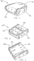
- FIGS. 1 through 7 illustrate example embodiments of a safety belt buckle 100 manufactured in accordance with the present invention.
- the safety belt buckle 100 includes a base member 102 and a release member 104 coupled to the base member.
- the release member 104 is configured to release a tongue held between the release member and the base member 102 when the release member 104 is pulled away from the base member 102.
- a safety belt includes two strap portions that wrap around a passenger to secure the passenger to a seat or any other passenger support structure.
- the safety belt has a tongue coupled to an end of a first strap portion and a safety belt buckle 100 coupled to an end of a second strap portion.
- the tongue is configured to mate with the safety belt buckle 100.
- the safety belt buckle 100 can include a slot 106 disposed at a front portion of the safety belt buckle 100 and configured to receive the tongue. The tongue is then held in between the base member 102 and the release member 104 until the passenger lifts or pulls the release member 104 away from the base member 102 to unlatch the tongue from the safety belt buckle 100.
- the safety belt buckle 100a can be manufactured to have various design features and/or according to different form factors.
- FIG. 1 illustrates an example of the safety belt buckle 100 with a simple design.
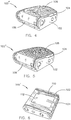
- FIG. 2 illustrates an example of the safety belt buckle 100b with a more complex design that includes a 3D pattern 108 of parallelograms formed on a top surface of the release member 104.
- the safety belt buckle 100 can also include other indentations or protuberances formed on the release member 104 and/or the base member 102.
- the safety belt buckle 100 may also include paint or other colored material (e.g., colored plastic, rubber, or metal) formed on the top surface, upon protuberances on the top surface, and/or within indentations formed in the top surface of the release member 104.
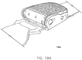
- FIGS. 4 and 5 also illustrate examples of the safety belt buckle 100d, 100e with 3D patterns 108 on the top surface of the release member 104.
- the 3D pattern 108 on a release member 104 (and/or a base member 102) includes a repeating pattern of geometric shapes.
- the 3D pattern 108 in FIG.4 includes repeating diamonds
- the 3D pattern in FIG. 5 includes repeating chevrons.
- FIG. 3 illustrates another example of the safety belt buckle 100c with a complex design that includes raised edges on the release member 104 for a more distinctive appearance.
- FIG. 6 illustrates an example of the safety belt buckle 100f, that is manufactured with a method that is in the scope of the present invention, with a design similar to the safety belt buckle 100 illustrated in FIG. 3 , where the release member 104 includes a recess 110 with an in-mold feature 112 disposed (e.g., embedded) within the recess 110.
- the in-mold feature 112 can be injection molded with the release member 104 structure and/or the release member 104 structure can be cast around the in-mold feature 112.
- any other safety belt buckle 100 can include an in-mold feature 112.
- the in-mold feature 112 includes a pattern (e.g., a geometric pattern) or design.
- the in-mold feature 112 can additionally or alternatively include a brand name, a logo, and/or a message.
- the in-mold feature 112 includes an informational message (e.g., a safety message or warning).
- the in-mold feature 112 includes a promotional message (e.g., an advertisement).
- the in-mold feature 112 can include an advertisement paid for by a commercial entity wishing to advertise products or services on an aircraft or other vehicle (e.g., bus, train, etc.) that includes the safety belt buckles 100.
- an in-mold labeling (IML) or in-mold decorating (IMD) process can be used to add an in-mold feature 112 comprising a thin sheet/film embedded within the top surface of the release member 104 (e.g., where the release member 104 may be an injection molded structure).
- the sheet/film may have ink applied to the sheet/film.
- the ink can be printed in the form of a pattern, grain, wording, miscellaneous branding, etc. This ink could be a single color or multicolor.
- the ink could also be applied to either side of the sheet/film.
- the sheet/film could range in thickness and texture type (including soft touch). Techniques other than IML/IMD can be implemented to achieve desired effects. This can include, but is not limited to, metallic pigments in the material, in mold painting, hydro dipping, electroplating, vacuum metalization, thermo/pressure forming, etc.
- the in-mold feature 112 includes a film, sheet, or injection molded chip of plastic can be integrated into a designated area of the release member 104.
- This film, sheet, or injection molded chip can be held in with adhesive, mechanically, magnetically, or by other similar means.
- the film, sheet, or injection molded chip may have the option to be permanent or removable (e.g., interchangeable).
- ink is printed on a sheet/film (potentially with a distorted image to compensate for the stretching/warping during the forming process).
- the sheet/film is thermoformed, pressure formed, or formed by any other forming technology to create the shape of the part.
- the sheet/film can be trimmed down to the desired shape of the part.
- Static electricity, mechanical fixtures, or other tools or devices are used to hold the sheet/film into an injection mold. Molten plastic is then flown into the mold behind the sheet/film, filling the cavity and causing the sheet/film and injection molding material to become one complete item (e.g., the release member 104 with the in-mold feature 112 embedded therein).
- FIG. 7 illustrates an example of the safety belt buckle 100g manufactured according to the invention, with the release member 104 including a 3D graphic 114 printed on a top surface of the release member 104.
- the 3D graphic 114 may be formed by one or more printed device layers of a plurality of printed device layers that form the release member 104 and/or the base member 102 of the safety belt buckle 100.
- the 3D graphic 114 includes a 3D pattern (e.g., a geometric pattern) or design.
- the 3D graphic 114 can additionally or alternatively include a brand name, a logo, and/or a message.
- the 3D graphic 114 includes an informational message (e.g., a safety message or warning).
- the 3D graphic 114 includes a promotional message (e.g., an advertisement).
- the 3D graphic 114 can include an advertisement paid for by a commercial entity wishing to advertise products or services on an aircraft or other vehicle (e.g., bus, train, etc.) that includes the safety belt buckles 100.
- the 3D graphic 114 has paint or other colored material (e.g., colored plastic, rubber, or metal) disposed upon and/or forming a portion of the 3D graphic 114.
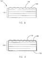
- FIG. 8 illustrates a cross-sectional view of the release member 104 of the safety belt buckle 100 manufactured in accordance with the current invention.
- the release member 104 is formed by a plurality of printed device layers 116 (e.g., printed metal and/or plastic device layers).
- the printed device layers 116 are metal device layers formed on top of one another using a 3D printer or other type of additive manufacturing device.
- One or more of the printed device layers 116 can form a 3D pattern 108 on a top surface of the release member 104.
- a colored layer 118 e.g., a paint layer, other colored material, and/or another (colored) printed device layer
- FIG. 9 illustrates a cross-sectional view of the release member 104 of the safety belt buckle 100 manufactured in accordance with the current invention.
- the release member 104 can be formed by a plurality of printed device layers 120 (e.g., printed metal and/or plastic device layers).
- a surface coating 122 e.g., metallic coating, plastic coating, rubberized coating, or the like
- the printed device layers 120 are plastic device layers formed on top of one another using a 3D printer or other type of additive manufacturing device, and the surface coating 122 is a metal coating disposed upon the plurality of printed device layers 120.
- One or more of the printed device layers 120 can form a 3D pattern 108 on a top surface of the release member 104.
- a colored layer 118 e.g., a paint layer, other colored material, and/or another (colored) printed device layer
- FIG. 10 illustrates a cross-sectional view of the release member 104 of the safety belt buckle 100 manufactured in accordance with the current invention.
- the release member 104 is formed by a plurality of printed device layers 116 (e.g., printed metal and/or plastic device layers).
- the printed device layers 116 are metal device layers formed on top of one another using a 3D printer or other type of additive manufacturing device.
- One or more of the printed device layers 116 can form a 3D graphic 114 on a top surface of the release member 104.
- a colored layer 118 e.g., a paint layer, other colored material, and/or another (colored) printed device layer
- FIG. 11 illustrates a cross-sectional view of the release member 104 of the safety belt buckle 100 manufactured in accordance with the current invention.
- the release member 104 can be formed by a plurality of printed device layers 120 (e.g., printed metal and/or plastic device layers).
- a surface coating 122 e.g., metallic coating, plastic coating, rubberized coating, or the like
- the printed device layers 120 are plastic device layers formed on top of one another using a 3D printer or other type of additive manufacturing device, and the surface coating 122 is a metal coating disposed upon the plurality of printed device layers 120.
- One or more of the printed device layers 120 can form a 3D graphic 114 on a top surface of the release member 104.
- a colored layer 118 e.g., a paint layer, other colored material, and/or another (colored) printed device layer
- FIGS. 12A through 12C illustrate an example of a 3D printer 200 forming a plurality of printed device layers (e.g., printed device layers 116 or 120) to manufacture a safety belt buckle 100 or at least a portion thereof (e.g., the base member 102 and/or the release member 104).
- the 3D printer 200 includes one or more feeders configured to feed one or more strands of device material (e.g., metal and/or plastic 3D print filament) to a print nozzle 202 (or an assembly of print nozzles).
- the 3D printer 200 may further include a stage 206 configured to support printed device layers and an arm 204 configured to hold the print nozzle 202 above the stage 206.
- the stage 206 and/or the arm 204 can be configured to actuate (e.g., up, down, forwards, backwards, and/or sideways) so that the printed device layers can be disposed upon one another to form a 3D printed structure (e.g., base member 102 and/or release member 104).
- the 3D printer 200 illustrated in FIGS. 12A through 12C is provided as an example, and it is to be understood that other types of 3D printers can be employed.
- the base member 102 and/or release member 104 structures may be formed from any 3D printing material or combination of materials that meet structural specifications for the safety belt buckle 100 structures described herein.
- 3D printing materials include, but are not limited to: Polylactic Acid (PLA) printing filament; Acrylonitrile Butadiene Styrene (ABS) printing filament; PRO Series PLA printing filament; PRO Series ABS printing filament; Polyamide (aka Nylon) printing filament; Polyamide With Chopped Carbon Fiber Strands (aka NylonX) printing filament; PRO Series Nylon printing filament; Polyethylene terephthalate (PET) printing filament; PETG printing filament; PETT printing filament; PRO Series PET, PETG, or PETT printing filament; Acrylonitrile Styrene Acrylate (ASA) printing filament; PolyPropylene (PP) printing filament; and combinations thereof.
- any combination of the foregoing device materials may be included in example examples of the safety belt buckle 100 described herein.
- the foregoing list of device materials is not exhaustive, and it is contemplated that other device materials with similar structural properties and/or metals can be used in combination with or in place of the listed device materials.
- the safety belt buckle 100 or at least a portion thereof is plated or otherwise covered by a surface coating 122 (e.g., a metal coating).
- a surface coating 122 e.g., a metal coating
- FIGS. 9 and 11 illustrate examples of the safety belt buckle 100 with a surface coating 122 disposed upon the printed layers 120 that form the release member 104.
- the surface coating 122 is applied by a coating system 300 that includes a conveyer 302 configured to transport the safety belt buckle 100 or at least a portion thereof (e.g., base member 102 and/or release member 104) to a container 304 with surface coating material 122 (e.g., electroplating solution) disposed therein.
- the safety belt buckle 100 structure (e.g., base member 102 and/or release member 104) can then be submerged within the surface coating material 122 to cover the safety belt buckle 100 structure (e.g., base member 102 and/or release member 104) with the surface coating 122.
- the surface coating material 122 can be poured onto or otherwise deposited onto the surface of the safety belt buckle 100 structure (e.g., base member 102 and/or release member 104).
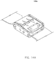
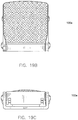
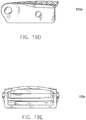
- FIGS. 14A through 19G illustrate additional views of some of the examples of the safety belt buckle 100 described herein.
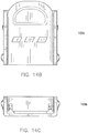
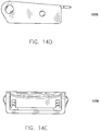
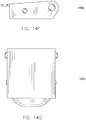
- FIGS. 14A through 14G illustrate additional views of the example of the safety belt buckle 100b illustrated in FIG. 2
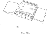
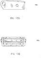
- FIGS. 15A through 15G illustrate additional views of the example of the safety belt buckle 100c illustrated in FIG. 3
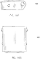
- FIGS. 16A through 16G illustrate additional views of the example of the safety belt buckle 100f illustrated in FIG. 6
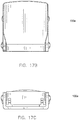
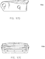
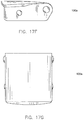
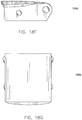
- FIGS. 17A through 17G illustrate additional views of the example of the safety belt buckle 100a illustrated in FIG. 1
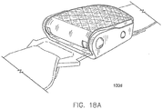
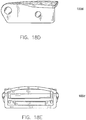
- FIGS. 18A through 18G illustrate additional views of the example of the safety belt buckle 100d illustrated in FIG. 4
- FIGS. 19A through 19G illustrate additional views of the example of the safety belt buckle 100e illustrated in FIG. 5 .
- methods according to the invention disclosed herein may include one or more of the steps described herein. Further, such steps may be carried out in any desired order and two or more of the steps may be carried out simultaneously with one another. Two or more of the steps disclosed herein may be combined in a single step, and in some embodiments, one or more of the steps may be carried out as two or more sub-steps. Further, other steps or sub-steps may be carried in addition to, or as substitutes to one or more of the steps disclosed herein.
Landscapes
- Automotive Seat Belt Assembly (AREA)
Claims (10)
- Verfahren zur Herstellung eines Sicherheitsgurtschlosses (100), wobei das Sicherheitsgurtschloss (100) Folgendes umfasst:Bereitstellen eines Basiselements (102); undBereitstellen eines Freigabeelements (104), wobei das Freigabeelement (104) dazu ausgelegt ist, eine zwischen dem Freigabeelement (104) und dem Basiselement (102) gehaltene Zunge freizugeben, wenn das Freigabeelement (104) vom Basiselement (102) weggezogen wird,Koppeln des Freigabeelements (104) mit dem Basiselement (102), gekennzeichnet durch den Schritt des Herstellens des Freigabeelements (104) durch Drucken von mehreren Vorrichtungsschichten und Anordnen einer Metallbeschichtung (122) über den mehreren gedruckten Vorrichtungsschichten (116, 120).
- Verfahren zur Herstellung eines Sicherheitsgurtschlosses nach Anspruch 1, wobei Drucken der Vorrichtungsschichten Drucken von einer oder mehreren Metallschichten umfasst.
- Verfahren zur Herstellung eines Sicherheitsgurtschlosses nach Anspruch 1 oder 2, wobei Drucken der Vorrichtungsschichten Drucken von einer oder mehreren nicht-metallischen Schichten umfasst.
- Verfahren zur Herstellung eines Sicherheitsgurtschlosses nach einem oder mehreren der Ansprüche 1-3, wobei die mehreren Vorrichtungsschichten (116, 120) gedruckt werden, um ein dreidimensionales Muster (108) auf dem Freigabeelement (104) zu bilden.
- Verfahren zur Herstellung eines Sicherheitsgurtschlosses nach Anspruch 4, wobei das dreidimensionale Muster gedruckt wird, um ein sich wiederholendes Muster von geometrischen Formen bereitzustellen.
- Verfahren zur Herstellung eines Sicherheitsgurtschlosses nach Anspruch 4 oder 5, ferner umfassend Auflackierung einer Schicht auf dem dreidimensionalen Muster.
- Verfahren zur Herstellung eines Sicherheitsgurtschlosses nach einem oder mehreren der Ansprüche 1-6, umfassend den Schritt des Bildens einer dreidimensionalen Grafik (114) aus den mehreren gedruckten Vorrichtungsschichten (116, 120) am Freigabeelement (104).
- Verfahren zur Herstellung eines Sicherheitsgurtschlosses nach Anspruch 7, wobei Bilden der dreidimensionalen Grafik zumindest Bilden von einem aus einem Markennamen oder einem Logo umfasst.
- Verfahren zur Herstellung eines Sicherheitsgurtschlosses nach Anspruch 7 oder 8, wobei Bilden der dreidimensionalen Grafik zumindest Bilden von einer aus einer Werbenachricht oder einer Informationsnachricht umfasst.
- Verfahren zur Herstellung eines Sicherheitsgurtschlosses nach einem oder mehreren der Ansprüche 7-9, ferner umfassend Auftragen einer Lackierungsschicht auf der dreidimensionalen Grafik.
Applications Claiming Priority (1)
| Application Number | Priority Date | Filing Date | Title |
|---|---|---|---|
| US15/948,815 US10485305B2 (en) | 2018-04-09 | 2018-04-09 | Passenger safety belt buckles |
Publications (3)
| Publication Number | Publication Date |
|---|---|
| EP3552511A2 EP3552511A2 (de) | 2019-10-16 |
| EP3552511A3 EP3552511A3 (de) | 2019-11-20 |
| EP3552511B1 true EP3552511B1 (de) | 2021-06-02 |
Family
ID=66101926
Family Applications (1)
| Application Number | Title | Priority Date | Filing Date |
|---|---|---|---|
| EP19167541.2A Active EP3552511B1 (de) | 2018-04-09 | 2019-04-05 | Verfahren zur herstellung einer sicherheitsgurtschlösser |
Country Status (3)
| Country | Link |
|---|---|
| US (1) | US10485305B2 (de) |
| EP (1) | EP3552511B1 (de) |
| CN (1) | CN110353364B (de) |
Families Citing this family (3)
| Publication number | Priority date | Publication date | Assignee | Title |
|---|---|---|---|---|
| USD853277S1 (en) * | 2018-04-06 | 2019-07-09 | Rockwell Collins, Inc. | Passenger safety belt buckle |
| USD1106873S1 (en) * | 2024-08-06 | 2025-12-23 | Joshua Landry | Buckle |
| USD1106874S1 (en) * | 2023-12-27 | 2025-12-23 | Joshua Landry | Buckle |
Family Cites Families (27)
| Publication number | Priority date | Publication date | Assignee | Title |
|---|---|---|---|---|
| SE360017B (de) * | 1971-04-13 | 1973-09-17 | Holmberg Gote Eskil Yngve | |
| DE2341601A1 (de) * | 1973-08-17 | 1975-02-27 | Artur Foehl | Verschluss fuer sicherheitsgurte |
| GB1550182A (en) * | 1976-04-13 | 1979-08-08 | Kangol Magnet Ltd | Seat belt systems |
| DE2741297A1 (de) * | 1977-09-14 | 1979-03-22 | Lothar Depmeyer | Sicherheitsgurt fuer kraftfahrzeuge |
| DE3000969A1 (de) * | 1979-01-17 | 1980-08-07 | Kangol Magnet Ltd | Gurtschnalle fuer kraftfahrzeug- sicherheitsgurte |
| US4502188A (en) * | 1983-04-05 | 1985-03-05 | Buxton, Inc. | Theme belt buckle |
| DD217704A1 (de) * | 1983-09-01 | 1985-01-23 | Doebelner Beschlaege Metall | Verschluss fuer sicherheitsgurte |
| US4766654A (en) * | 1984-10-19 | 1988-08-30 | Katsuyama Kinzoku Kogyo Kabushiki Kaisha | Push button buckle assembly for a seat belt |
| ES8706315A1 (es) * | 1986-03-25 | 1987-06-16 | Arnau Fernandez Mayoralas Joaq | Cinturones de seguridad para vehiculos de multiples funciones con broche manual y automatico |
| IT218275Z2 (it) * | 1989-08-10 | 1992-04-14 | Vittorio Romano Barbuti | Dispositivo di sganciamento rapido per cinture di sicurezza per automobili |
| US5765265A (en) * | 1997-06-05 | 1998-06-16 | Kang; Koo Seong | Belt buckle |
| US5926927A (en) * | 1997-12-13 | 1999-07-27 | Winkler; Marvin | Enhanced adjustable slider buckle means |
| US6237197B1 (en) * | 1999-04-28 | 2001-05-29 | Richard Cahill Donahue | Golf cart buckle lever retaining clip |
| US7566140B2 (en) * | 2005-09-09 | 2009-07-28 | Sevilla Ii Frederick J | Self illuminating belt buckle |
| US9480308B2 (en) * | 2007-10-12 | 2016-11-01 | Ford Global Technologies, Llc | Buckle-tongue arrangement for four point seat belt system |
| GB0905538D0 (en) | 2009-03-31 | 2009-05-13 | Cobra Uk Automotive Products D | Aircraft seat |
| US8763210B2 (en) * | 2010-01-15 | 2014-07-01 | Gv Snowshoes | Locking device for a buckle |
| WO2012117326A2 (en) * | 2011-02-28 | 2012-09-07 | Roland Iten | Mechanical lever buckle for belt and watch strap |
| US20120284972A1 (en) * | 2011-05-09 | 2012-11-15 | Hafdal Jane E | Belt Buckle Accessory |
| TW201343098A (zh) * | 2012-04-23 | 2013-11-01 | yong-fa Su | 皮帶頭結構 |
| US20140259303A1 (en) * | 2013-03-15 | 2014-09-18 | Eric N. Eliason | Belt buckle with exchangable face plate |
| GB2524978A (en) | 2014-04-07 | 2015-10-14 | Wrasp Ltd | Buckle and seat belt comprising a buckle |
| CN104375695B (zh) * | 2014-08-27 | 2017-10-17 | 合肥京东方显示光源有限公司 | 穿戴式显示设备、皮带扣及皮带 |
| US10226106B2 (en) * | 2015-03-27 | 2019-03-12 | Filip Postolek | Locking buckle |
| US10080399B2 (en) * | 2016-02-25 | 2018-09-25 | Wendy Jeanne Ozburn | Buckle locket |
| US10160419B2 (en) * | 2016-12-07 | 2018-12-25 | Bestop Prp, Llc | Belt ratcheting system with dual rollers and adjustable release buckle |
| US10064452B1 (en) | 2017-06-30 | 2018-09-04 | Ford Global Technologies, Llc | Seatbelt tongue |
-
2018
- 2018-04-09 US US15/948,815 patent/US10485305B2/en active Active
-
2019
- 2019-04-05 EP EP19167541.2A patent/EP3552511B1/de active Active
- 2019-04-08 CN CN201910273990.9A patent/CN110353364B/zh active Active
Non-Patent Citations (1)
| Title |
|---|
| None * |
Also Published As
| Publication number | Publication date |
|---|---|
| CN110353364B (zh) | 2024-11-05 |
| US20190307212A1 (en) | 2019-10-10 |
| EP3552511A2 (de) | 2019-10-16 |
| CN110353364A (zh) | 2019-10-22 |
| US10485305B2 (en) | 2019-11-26 |
| EP3552511A3 (de) | 2019-11-20 |
Similar Documents
| Publication | Publication Date | Title |
|---|---|---|
| EP3552511B1 (de) | Verfahren zur herstellung einer sicherheitsgurtschlösser | |
| JP2988868B2 (ja) | エッジ表面が被覆されたプラスチック部材を得るためのインサート成形方法およびそれにより製造されたプラスチック部材 | |
| CN108528378A (zh) | 具有金属化表面的成型聚合物结构 | |
| US6436329B1 (en) | Method of making fused film plastic parts and parts made by such methods | |
| US20130189456A1 (en) | Magnetic Hood Ornament | |
| CN109049522A (zh) | 一种带膜外饰件玻璃总成及其制造方法 | |
| CN101856856A (zh) | 模内成型立体花纹的方法及其模制品 | |
| US20060121251A1 (en) | Method for production of an object and object produced by said method | |
| EP2683537B1 (de) | Verzierte thermoplastische folien und herstellungsverfahren dafür | |
| US9849844B2 (en) | Custom badges for vehicles | |
| US10239242B2 (en) | Method of manufacturing emergency lamp switch | |
| KR100814663B1 (ko) | 자동차용 엠블럼 및 그 제조방법 | |
| CN211581788U (zh) | 徽章 | |
| EP2687412B1 (de) | Abdeckung für ein Gasbeutelmodul, Gasbeutelmodul mit der Abdeckung, Lenkrad und Verfahren zur Herstellung der Abdeckung | |
| CN217777839U (zh) | 机动车辆的车身零件 | |
| GB2415406A (en) | A decorative trim and method of manufacture | |
| JP3754627B2 (ja) | メッキ調自動車外装品及びその製造方法 | |
| KR20100138490A (ko) | 자동차 엠블럼 및 그 제조방법 | |
| KR100799768B1 (ko) | 자동차 부품의 엠블럼 및 그 제조방법 | |
| KR20180138305A (ko) | 일체형 엠블럼 제조장치 및 그 제조방법 | |
| JP4184528B2 (ja) | 射出成形同時絵付方法及びそれに用いる絵付用成形型 | |
| US20080224342A1 (en) | Method For Forming Two-Tone Parts For Automotive Interior Applications | |
| JPH0534904Y2 (de) | ||
| CN210416451U (zh) | 一种二次注塑的车标装饰件 | |
| JP2013112155A (ja) | 自動車用エンブレム |
Legal Events
| Date | Code | Title | Description |
|---|---|---|---|
| PUAI | Public reference made under article 153(3) epc to a published international application that has entered the european phase |
Free format text: ORIGINAL CODE: 0009012 |
|
| STAA | Information on the status of an ep patent application or granted ep patent |
Free format text: STATUS: THE APPLICATION HAS BEEN PUBLISHED |
|
| AK | Designated contracting states |
Kind code of ref document: A2 Designated state(s): AL AT BE BG CH CY CZ DE DK EE ES FI FR GB GR HR HU IE IS IT LI LT LU LV MC MK MT NL NO PL PT RO RS SE SI SK SM TR |
|
| AX | Request for extension of the european patent |
Extension state: BA ME |
|
| PUAL | Search report despatched |
Free format text: ORIGINAL CODE: 0009013 |
|
| AK | Designated contracting states |
Kind code of ref document: A3 Designated state(s): AL AT BE BG CH CY CZ DE DK EE ES FI FR GB GR HR HU IE IS IT LI LT LU LV MC MK MT NL NO PL PT RO RS SE SI SK SM TR |
|
| AX | Request for extension of the european patent |
Extension state: BA ME |
|
| RIC1 | Information provided on ipc code assigned before grant |
Ipc: A44B 11/25 20060101AFI20191014BHEP |
|
| STAA | Information on the status of an ep patent application or granted ep patent |
Free format text: STATUS: REQUEST FOR EXAMINATION WAS MADE |
|
| STAA | Information on the status of an ep patent application or granted ep patent |
Free format text: STATUS: EXAMINATION IS IN PROGRESS |
|
| 17P | Request for examination filed |
Effective date: 20200520 |
|
| RBV | Designated contracting states (corrected) |
Designated state(s): AL AT BE BG CH CY CZ DE DK EE ES FI FR GB GR HR HU IE IS IT LI LT LU LV MC MK MT NL NO PL PT RO RS SE SI SK SM TR |
|
| 17Q | First examination report despatched |
Effective date: 20200619 |
|
| GRAP | Despatch of communication of intention to grant a patent |
Free format text: ORIGINAL CODE: EPIDOSNIGR1 |
|
| STAA | Information on the status of an ep patent application or granted ep patent |
Free format text: STATUS: GRANT OF PATENT IS INTENDED |
|
| RIN1 | Information on inventor provided before grant (corrected) |
Inventor name: PRINCIP, MICHAEL Inventor name: JOHNSON, GLENN A. Inventor name: HANSSON, CHARLES MARTIN Inventor name: VELET, ALEX L. Inventor name: LIN, JAAN Inventor name: MARTZ, THOMAS Inventor name: WENGER, BRIAN P. |
|
| INTG | Intention to grant announced |
Effective date: 20201222 |
|
| GRAS | Grant fee paid |
Free format text: ORIGINAL CODE: EPIDOSNIGR3 |
|
| GRAA | (expected) grant |
Free format text: ORIGINAL CODE: 0009210 |
|
| STAA | Information on the status of an ep patent application or granted ep patent |
Free format text: STATUS: THE PATENT HAS BEEN GRANTED |
|
| REG | Reference to a national code |
Ref country code: CH Ref legal event code: EP |
|
| AK | Designated contracting states |
Kind code of ref document: B1 Designated state(s): AL AT BE BG CH CY CZ DE DK EE ES FI FR GB GR HR HU IE IS IT LI LT LU LV MC MK MT NL NO PL PT RO RS SE SI SK SM TR |
|
| REG | Reference to a national code |
Ref country code: GB Ref legal event code: FG4D |
|
| REG | Reference to a national code |
Ref country code: AT Ref legal event code: REF Ref document number: 1397629 Country of ref document: AT Kind code of ref document: T Effective date: 20210615 |
|
| REG | Reference to a national code |
Ref country code: IE Ref legal event code: FG4D |
|
| REG | Reference to a national code |
Ref country code: DE Ref legal event code: R096 Ref document number: 602019004972 Country of ref document: DE |
|
| REG | Reference to a national code |
Ref country code: LT Ref legal event code: MG9D |
|
| PG25 | Lapsed in a contracting state [announced via postgrant information from national office to epo] |
Ref country code: FI Free format text: LAPSE BECAUSE OF FAILURE TO SUBMIT A TRANSLATION OF THE DESCRIPTION OR TO PAY THE FEE WITHIN THE PRESCRIBED TIME-LIMIT Effective date: 20210602 Ref country code: HR Free format text: LAPSE BECAUSE OF FAILURE TO SUBMIT A TRANSLATION OF THE DESCRIPTION OR TO PAY THE FEE WITHIN THE PRESCRIBED TIME-LIMIT Effective date: 20210602 Ref country code: LT Free format text: LAPSE BECAUSE OF FAILURE TO SUBMIT A TRANSLATION OF THE DESCRIPTION OR TO PAY THE FEE WITHIN THE PRESCRIBED TIME-LIMIT Effective date: 20210602 Ref country code: BG Free format text: LAPSE BECAUSE OF FAILURE TO SUBMIT A TRANSLATION OF THE DESCRIPTION OR TO PAY THE FEE WITHIN THE PRESCRIBED TIME-LIMIT Effective date: 20210902 |
|
| REG | Reference to a national code |
Ref country code: NL Ref legal event code: MP Effective date: 20210602 |
|
| REG | Reference to a national code |
Ref country code: AT Ref legal event code: MK05 Ref document number: 1397629 Country of ref document: AT Kind code of ref document: T Effective date: 20210602 |
|
| PG25 | Lapsed in a contracting state [announced via postgrant information from national office to epo] |
Ref country code: GR Free format text: LAPSE BECAUSE OF FAILURE TO SUBMIT A TRANSLATION OF THE DESCRIPTION OR TO PAY THE FEE WITHIN THE PRESCRIBED TIME-LIMIT Effective date: 20210903 Ref country code: RS Free format text: LAPSE BECAUSE OF FAILURE TO SUBMIT A TRANSLATION OF THE DESCRIPTION OR TO PAY THE FEE WITHIN THE PRESCRIBED TIME-LIMIT Effective date: 20210602 Ref country code: SE Free format text: LAPSE BECAUSE OF FAILURE TO SUBMIT A TRANSLATION OF THE DESCRIPTION OR TO PAY THE FEE WITHIN THE PRESCRIBED TIME-LIMIT Effective date: 20210602 Ref country code: NO Free format text: LAPSE BECAUSE OF FAILURE TO SUBMIT A TRANSLATION OF THE DESCRIPTION OR TO PAY THE FEE WITHIN THE PRESCRIBED TIME-LIMIT Effective date: 20210902 Ref country code: LV Free format text: LAPSE BECAUSE OF FAILURE TO SUBMIT A TRANSLATION OF THE DESCRIPTION OR TO PAY THE FEE WITHIN THE PRESCRIBED TIME-LIMIT Effective date: 20210602 Ref country code: PL Free format text: LAPSE BECAUSE OF FAILURE TO SUBMIT A TRANSLATION OF THE DESCRIPTION OR TO PAY THE FEE WITHIN THE PRESCRIBED TIME-LIMIT Effective date: 20210602 |
|
| PG25 | Lapsed in a contracting state [announced via postgrant information from national office to epo] |
Ref country code: SK Free format text: LAPSE BECAUSE OF FAILURE TO SUBMIT A TRANSLATION OF THE DESCRIPTION OR TO PAY THE FEE WITHIN THE PRESCRIBED TIME-LIMIT Effective date: 20210602 Ref country code: EE Free format text: LAPSE BECAUSE OF FAILURE TO SUBMIT A TRANSLATION OF THE DESCRIPTION OR TO PAY THE FEE WITHIN THE PRESCRIBED TIME-LIMIT Effective date: 20210602 Ref country code: ES Free format text: LAPSE BECAUSE OF FAILURE TO SUBMIT A TRANSLATION OF THE DESCRIPTION OR TO PAY THE FEE WITHIN THE PRESCRIBED TIME-LIMIT Effective date: 20210602 Ref country code: AT Free format text: LAPSE BECAUSE OF FAILURE TO SUBMIT A TRANSLATION OF THE DESCRIPTION OR TO PAY THE FEE WITHIN THE PRESCRIBED TIME-LIMIT Effective date: 20210602 Ref country code: CZ Free format text: LAPSE BECAUSE OF FAILURE TO SUBMIT A TRANSLATION OF THE DESCRIPTION OR TO PAY THE FEE WITHIN THE PRESCRIBED TIME-LIMIT Effective date: 20210602 Ref country code: RO Free format text: LAPSE BECAUSE OF FAILURE TO SUBMIT A TRANSLATION OF THE DESCRIPTION OR TO PAY THE FEE WITHIN THE PRESCRIBED TIME-LIMIT Effective date: 20210602 Ref country code: PT Free format text: LAPSE BECAUSE OF FAILURE TO SUBMIT A TRANSLATION OF THE DESCRIPTION OR TO PAY THE FEE WITHIN THE PRESCRIBED TIME-LIMIT Effective date: 20211004 Ref country code: NL Free format text: LAPSE BECAUSE OF FAILURE TO SUBMIT A TRANSLATION OF THE DESCRIPTION OR TO PAY THE FEE WITHIN THE PRESCRIBED TIME-LIMIT Effective date: 20210602 Ref country code: SM Free format text: LAPSE BECAUSE OF FAILURE TO SUBMIT A TRANSLATION OF THE DESCRIPTION OR TO PAY THE FEE WITHIN THE PRESCRIBED TIME-LIMIT Effective date: 20210602 |
|
| REG | Reference to a national code |
Ref country code: DE Ref legal event code: R097 Ref document number: 602019004972 Country of ref document: DE |
|
| PLBE | No opposition filed within time limit |
Free format text: ORIGINAL CODE: 0009261 |
|
| STAA | Information on the status of an ep patent application or granted ep patent |
Free format text: STATUS: NO OPPOSITION FILED WITHIN TIME LIMIT |
|
| PG25 | Lapsed in a contracting state [announced via postgrant information from national office to epo] |
Ref country code: DK Free format text: LAPSE BECAUSE OF FAILURE TO SUBMIT A TRANSLATION OF THE DESCRIPTION OR TO PAY THE FEE WITHIN THE PRESCRIBED TIME-LIMIT Effective date: 20210602 |
|
| 26N | No opposition filed |
Effective date: 20220303 |
|
| PG25 | Lapsed in a contracting state [announced via postgrant information from national office to epo] |
Ref country code: AL Free format text: LAPSE BECAUSE OF FAILURE TO SUBMIT A TRANSLATION OF THE DESCRIPTION OR TO PAY THE FEE WITHIN THE PRESCRIBED TIME-LIMIT Effective date: 20210602 |
|
| PG25 | Lapsed in a contracting state [announced via postgrant information from national office to epo] |
Ref country code: IT Free format text: LAPSE BECAUSE OF FAILURE TO SUBMIT A TRANSLATION OF THE DESCRIPTION OR TO PAY THE FEE WITHIN THE PRESCRIBED TIME-LIMIT Effective date: 20210602 |
|
| REG | Reference to a national code |
Ref country code: CH Ref legal event code: PL |
|
| REG | Reference to a national code |
Ref country code: BE Ref legal event code: MM Effective date: 20220430 |
|
| PG25 | Lapsed in a contracting state [announced via postgrant information from national office to epo] |
Ref country code: MC Free format text: LAPSE BECAUSE OF FAILURE TO SUBMIT A TRANSLATION OF THE DESCRIPTION OR TO PAY THE FEE WITHIN THE PRESCRIBED TIME-LIMIT Effective date: 20210602 Ref country code: LU Free format text: LAPSE BECAUSE OF NON-PAYMENT OF DUE FEES Effective date: 20220405 Ref country code: LI Free format text: LAPSE BECAUSE OF NON-PAYMENT OF DUE FEES Effective date: 20220430 Ref country code: CH Free format text: LAPSE BECAUSE OF NON-PAYMENT OF DUE FEES Effective date: 20220430 |
|
| PG25 | Lapsed in a contracting state [announced via postgrant information from national office to epo] |
Ref country code: BE Free format text: LAPSE BECAUSE OF NON-PAYMENT OF DUE FEES Effective date: 20220430 |
|
| PG25 | Lapsed in a contracting state [announced via postgrant information from national office to epo] |
Ref country code: IE Free format text: LAPSE BECAUSE OF NON-PAYMENT OF DUE FEES Effective date: 20220405 |
|
| PG25 | Lapsed in a contracting state [announced via postgrant information from national office to epo] |
Ref country code: HU Free format text: LAPSE BECAUSE OF FAILURE TO SUBMIT A TRANSLATION OF THE DESCRIPTION OR TO PAY THE FEE WITHIN THE PRESCRIBED TIME-LIMIT; INVALID AB INITIO Effective date: 20190405 |
|
| PG25 | Lapsed in a contracting state [announced via postgrant information from national office to epo] |
Ref country code: MK Free format text: LAPSE BECAUSE OF FAILURE TO SUBMIT A TRANSLATION OF THE DESCRIPTION OR TO PAY THE FEE WITHIN THE PRESCRIBED TIME-LIMIT Effective date: 20210602 Ref country code: CY Free format text: LAPSE BECAUSE OF FAILURE TO SUBMIT A TRANSLATION OF THE DESCRIPTION OR TO PAY THE FEE WITHIN THE PRESCRIBED TIME-LIMIT Effective date: 20210602 |
|
| PG25 | Lapsed in a contracting state [announced via postgrant information from national office to epo] |
Ref country code: MT Free format text: LAPSE BECAUSE OF FAILURE TO SUBMIT A TRANSLATION OF THE DESCRIPTION OR TO PAY THE FEE WITHIN THE PRESCRIBED TIME-LIMIT Effective date: 20210602 |
|
| PGFP | Annual fee paid to national office [announced via postgrant information from national office to epo] |
Ref country code: FR Payment date: 20250319 Year of fee payment: 7 |
|
| PGFP | Annual fee paid to national office [announced via postgrant information from national office to epo] |
Ref country code: GB Payment date: 20250319 Year of fee payment: 7 |
|
| PGFP | Annual fee paid to national office [announced via postgrant information from national office to epo] |
Ref country code: DE Payment date: 20250319 Year of fee payment: 7 |
|
| PG25 | Lapsed in a contracting state [announced via postgrant information from national office to epo] |
Ref country code: TR Free format text: LAPSE BECAUSE OF FAILURE TO SUBMIT A TRANSLATION OF THE DESCRIPTION OR TO PAY THE FEE WITHIN THE PRESCRIBED TIME-LIMIT Effective date: 20210602 |
|
| P01 | Opt-out of the competence of the unified patent court (upc) registered |
Free format text: CASE NUMBER: UPC_APP_0017919_3552511/2025 Effective date: 20251217 |