EP3552263B1 - Anode für eine festkörperoxidbrennstoffzelle - Google Patents
Anode für eine festkörperoxidbrennstoffzelle Download PDFInfo
- Publication number
- EP3552263B1 EP3552263B1 EP17817044.5A EP17817044A EP3552263B1 EP 3552263 B1 EP3552263 B1 EP 3552263B1 EP 17817044 A EP17817044 A EP 17817044A EP 3552263 B1 EP3552263 B1 EP 3552263B1
- Authority
- EP
- European Patent Office
- Prior art keywords
- anode
- steam reformation
- porous particles
- catalyst material
- particles
- Prior art date
- Legal status (The legal status is an assumption and is not a legal conclusion. Google has not performed a legal analysis and makes no representation as to the accuracy of the status listed.)
- Active
Links
Images


Classifications
-
- H—ELECTRICITY
- H01—ELECTRIC ELEMENTS
- H01M—PROCESSES OR MEANS, e.g. BATTERIES, FOR THE DIRECT CONVERSION OF CHEMICAL ENERGY INTO ELECTRICAL ENERGY
- H01M4/00—Electrodes
- H01M4/86—Inert electrodes with catalytic activity, e.g. for fuel cells
-
- H—ELECTRICITY
- H01—ELECTRIC ELEMENTS
- H01M—PROCESSES OR MEANS, e.g. BATTERIES, FOR THE DIRECT CONVERSION OF CHEMICAL ENERGY INTO ELECTRICAL ENERGY
- H01M4/00—Electrodes
- H01M4/86—Inert electrodes with catalytic activity, e.g. for fuel cells
- H01M4/8605—Porous electrodes
- H01M4/861—Porous electrodes with a gradient in the porosity
-
- H—ELECTRICITY
- H01—ELECTRIC ELEMENTS
- H01M—PROCESSES OR MEANS, e.g. BATTERIES, FOR THE DIRECT CONVERSION OF CHEMICAL ENERGY INTO ELECTRICAL ENERGY
- H01M4/00—Electrodes
- H01M4/86—Inert electrodes with catalytic activity, e.g. for fuel cells
- H01M4/8605—Porous electrodes
- H01M4/8621—Porous electrodes containing only metallic or ceramic material, e.g. made by sintering or sputtering
-
- H—ELECTRICITY
- H01—ELECTRIC ELEMENTS
- H01M—PROCESSES OR MEANS, e.g. BATTERIES, FOR THE DIRECT CONVERSION OF CHEMICAL ENERGY INTO ELECTRICAL ENERGY
- H01M4/00—Electrodes
- H01M4/86—Inert electrodes with catalytic activity, e.g. for fuel cells
- H01M4/8647—Inert electrodes with catalytic activity, e.g. for fuel cells consisting of more than one material, e.g. consisting of composites
- H01M4/8652—Inert electrodes with catalytic activity, e.g. for fuel cells consisting of more than one material, e.g. consisting of composites as mixture
-
- H—ELECTRICITY
- H01—ELECTRIC ELEMENTS
- H01M—PROCESSES OR MEANS, e.g. BATTERIES, FOR THE DIRECT CONVERSION OF CHEMICAL ENERGY INTO ELECTRICAL ENERGY
- H01M4/00—Electrodes
- H01M4/86—Inert electrodes with catalytic activity, e.g. for fuel cells
- H01M4/88—Processes of manufacture
- H01M4/8803—Supports for the deposition of the catalytic active composition
-
- H—ELECTRICITY
- H01—ELECTRIC ELEMENTS
- H01M—PROCESSES OR MEANS, e.g. BATTERIES, FOR THE DIRECT CONVERSION OF CHEMICAL ENERGY INTO ELECTRICAL ENERGY
- H01M4/00—Electrodes
- H01M4/86—Inert electrodes with catalytic activity, e.g. for fuel cells
- H01M4/88—Processes of manufacture
- H01M4/8825—Methods for deposition of the catalytic active composition
- H01M4/8846—Impregnation
-
- H—ELECTRICITY
- H01—ELECTRIC ELEMENTS
- H01M—PROCESSES OR MEANS, e.g. BATTERIES, FOR THE DIRECT CONVERSION OF CHEMICAL ENERGY INTO ELECTRICAL ENERGY
- H01M4/00—Electrodes
- H01M4/86—Inert electrodes with catalytic activity, e.g. for fuel cells
- H01M4/90—Selection of catalytic material
-
- H—ELECTRICITY
- H01—ELECTRIC ELEMENTS
- H01M—PROCESSES OR MEANS, e.g. BATTERIES, FOR THE DIRECT CONVERSION OF CHEMICAL ENERGY INTO ELECTRICAL ENERGY
- H01M4/00—Electrodes
- H01M4/86—Inert electrodes with catalytic activity, e.g. for fuel cells
- H01M4/90—Selection of catalytic material
- H01M4/9016—Oxides, hydroxides or oxygenated metallic salts
- H01M4/9025—Oxides specially used in fuel cell operating at high temperature, e.g. SOFC
-
- H—ELECTRICITY
- H01—ELECTRIC ELEMENTS
- H01M—PROCESSES OR MEANS, e.g. BATTERIES, FOR THE DIRECT CONVERSION OF CHEMICAL ENERGY INTO ELECTRICAL ENERGY
- H01M4/00—Electrodes
- H01M4/86—Inert electrodes with catalytic activity, e.g. for fuel cells
- H01M4/90—Selection of catalytic material
- H01M4/9041—Metals or alloys
- H01M4/905—Metals or alloys specially used in fuel cell operating at high temperature, e.g. SOFC
- H01M4/9066—Metals or alloys specially used in fuel cell operating at high temperature, e.g. SOFC of metal-ceramic composites or mixtures, e.g. cermets
-
- H—ELECTRICITY
- H01—ELECTRIC ELEMENTS
- H01M—PROCESSES OR MEANS, e.g. BATTERIES, FOR THE DIRECT CONVERSION OF CHEMICAL ENERGY INTO ELECTRICAL ENERGY
- H01M4/00—Electrodes
- H01M4/86—Inert electrodes with catalytic activity, e.g. for fuel cells
- H01M4/90—Selection of catalytic material
- H01M4/9075—Catalytic material supported on carriers, e.g. powder carriers
-
- H—ELECTRICITY
- H01—ELECTRIC ELEMENTS
- H01M—PROCESSES OR MEANS, e.g. BATTERIES, FOR THE DIRECT CONVERSION OF CHEMICAL ENERGY INTO ELECTRICAL ENERGY
- H01M8/00—Fuel cells; Manufacture thereof
- H01M8/06—Combination of fuel cells with means for production of reactants or for treatment of residues
- H01M8/0606—Combination of fuel cells with means for production of reactants or for treatment of residues with means for production of gaseous reactants
- H01M8/0612—Combination of fuel cells with means for production of reactants or for treatment of residues with means for production of gaseous reactants from carbon-containing material
- H01M8/0637—Direct internal reforming at the anode of the fuel cell
-
- H—ELECTRICITY
- H01—ELECTRIC ELEMENTS
- H01M—PROCESSES OR MEANS, e.g. BATTERIES, FOR THE DIRECT CONVERSION OF CHEMICAL ENERGY INTO ELECTRICAL ENERGY
- H01M4/00—Electrodes
- H01M4/86—Inert electrodes with catalytic activity, e.g. for fuel cells
- H01M2004/8678—Inert electrodes with catalytic activity, e.g. for fuel cells characterised by the polarity
- H01M2004/8684—Negative electrodes
-
- H—ELECTRICITY
- H01—ELECTRIC ELEMENTS
- H01M—PROCESSES OR MEANS, e.g. BATTERIES, FOR THE DIRECT CONVERSION OF CHEMICAL ENERGY INTO ELECTRICAL ENERGY
- H01M8/00—Fuel cells; Manufacture thereof
- H01M8/10—Fuel cells with solid electrolytes
- H01M8/12—Fuel cells with solid electrolytes operating at high temperature, e.g. with stabilised ZrO2 electrolyte
- H01M2008/1293—Fuel cells with solid oxide electrolytes
-
- Y—GENERAL TAGGING OF NEW TECHNOLOGICAL DEVELOPMENTS; GENERAL TAGGING OF CROSS-SECTIONAL TECHNOLOGIES SPANNING OVER SEVERAL SECTIONS OF THE IPC; TECHNICAL SUBJECTS COVERED BY FORMER USPC CROSS-REFERENCE ART COLLECTIONS [XRACs] AND DIGESTS
- Y02—TECHNOLOGIES OR APPLICATIONS FOR MITIGATION OR ADAPTATION AGAINST CLIMATE CHANGE
- Y02E—REDUCTION OF GREENHOUSE GAS [GHG] EMISSIONS, RELATED TO ENERGY GENERATION, TRANSMISSION OR DISTRIBUTION
- Y02E60/00—Enabling technologies; Technologies with a potential or indirect contribution to GHG emissions mitigation
- Y02E60/30—Hydrogen technology
- Y02E60/50—Fuel cells
-
- Y—GENERAL TAGGING OF NEW TECHNOLOGICAL DEVELOPMENTS; GENERAL TAGGING OF CROSS-SECTIONAL TECHNOLOGIES SPANNING OVER SEVERAL SECTIONS OF THE IPC; TECHNICAL SUBJECTS COVERED BY FORMER USPC CROSS-REFERENCE ART COLLECTIONS [XRACs] AND DIGESTS
- Y02—TECHNOLOGIES OR APPLICATIONS FOR MITIGATION OR ADAPTATION AGAINST CLIMATE CHANGE
- Y02P—CLIMATE CHANGE MITIGATION TECHNOLOGIES IN THE PRODUCTION OR PROCESSING OF GOODS
- Y02P70/00—Climate change mitigation technologies in the production process for final industrial or consumer products
- Y02P70/50—Manufacturing or production processes characterised by the final manufactured product
Definitions
- SOFCs Solid oxide fuel cells offer an efficient means of generating electricity from fuel gases.
- SOFCs consist of an anode and a cathode separated by a solid electrolyte material. Fuel gas and air are passed over the anode and cathode respectively at high temperatures to produce electricity.
- Various fuel cell architectures exists.
- a particularly preferred SOFC design is metal supported solid oxide fuel cells, such as those disclosed GB1476647 .
- SOFC cermet anodes consist of a porous mixture of an electronically conductive metallic phase (usually nickel or a nickel alloy) and a ceramic phase usually made of electrolyte material.
- Suitable metals with high electrocatalytic activity and low cost are usually transition metals (Ni, Fe, Cu, Co) which under SOFC operating temperatures will be reduced and oxidised based on the fuel and air supply to the cell. This repeated oxidation and reduction is often destructive due to the change in volume associated with it, and the fact that upon reduction the metal oxide frequently does not return to its original shape.
- Some systems use copper oxide which is used as a sintering aid to improve the cell's tolerance to this process. This is the case with cells possessing an architecture based on the Ceres Power Steel Cell design (see for example WO 02/34628 A1 ).
- EP 0 996 184 A2 is an example of high performance solid oxide fuel cell anode which is manufactured by impregnating nickel into the porous microstructure of an anode.
- the anode comprises nickel as well as agents adapted to resist coarsening of the nickel metal to ensure it retains a high surface area.
- GB 1,186,493 discloses electrodes that have been made using a variety of different materials for solid electrolyte fuel cells. This includes using mixed oxide layers containing praseodymium oxide, nickel oxide and chromium oxide. It is also chiefly directed towards cathodes.
- US 6,319,626 describes a high performance electrocatalyst based on transition metal perovskites of, among other elements, praseodymium which are reacted with yttrium-stabilised zirconia.
- US 2015/0244001 discloses a method of manufacturing cathodes involving CGO particles coated with praseodymium.
- an anode having excellent conductive properties, which catalyses the reactions within the cell and wherein the anode does not undergo a significant volume change through redox cycling. It would also be desirable to reduce the amount of nickel used to improve the effective lifetime of the cell, but in such a way that does not compromise on the conductivity of the anode.
- the invention is intended to overcome or at least ameliorate these problems.
- an anode for a solid oxide fuel cell comprising a matrix (25) comprising a doped metal oxide
- the inventors have surprisingly found that by introducing a metal steam reformation catalyst material into the anode material via a porous particle, this improves the efficiency of the SOFC and allows equivalent or greater cell performance to be achieved using a lower steam reformation catalyst material content.
- a metal steam reformation catalyst material into the anode material via a porous particle
- this improves the efficiency of the SOFC and allows equivalent or greater cell performance to be achieved using a lower steam reformation catalyst material content.
- porous particles typically with higher porosity than that of the anode material itself
- the steam reformation catalyst material is not particularly limited to any one substance.
- the steam reformation catalyst material is a metal, comprising an element selected from the group consisting of: Fe, Co, Ru, Ni, Rh, Pt, Pd or a combination thereof.
- the metal steam reformation catalyst material is most typically metallic and/or an alloy of different metals typically including at least one of those listed herein.
- the steam reformation catalyst material is selected from the group consisting of: Fe, Co, Ru, Ni, Rh, Pt, Pd or a combination thereof as these have good catalytic activity. Of these compounds, Fe, Co, Ni and combinations thereof are particularly preferred as they show good catalytic properties in steam reformation, are readily available and can be introduced into the porous "carrier" particles using simple techniques.
- the steam reformation catalyst comprises nickel as this has been shown to have optimal catalytic properties in steam reformation processes.
- the steam reformation catalyst may also comprise Mg (magnesium) and/or Al (aluminium). These elements have been found to improve the stability of the catalytic metal dispersion.
- the steam reformation catalyst material is trapped within the pores of the catalyst particles, meaning that the volume change associated with reduction and oxidation does not result in a change in the overall anode microstructure.
- the impregnated catalyst particles have a high specific surface area (typically higher than conventional porous anodes) leading to higher catalytic activity, particularly for steam reforming of methane.
- matrix as used herein is intended to refer to that portion of the anode which supports the porous particles.
- the matrix comprises doped metal oxide, it may comprise other ingredients and may form either a homogeneous or heterogeneous layer of material.
- Other anode components may be distributed throughout this matrix (uniformly or irregularly) and/or said components may be carried on part or all of the surface or surfaces of the matrix.
- the doped metal oxide is an electrically conducting ceramic material as such materials are well suited to the operational conditions of solid oxide fuel cells.
- the electrically conducting ceramic material is a rare-earth doped ceria.
- Such materials are not only stable under SOFC operating conditions, but also offer good electrical and structural properties and can be affixed well to substrates, especially metal substrates.
- the rare-earth doped ceria is selected from: gadolinium doped ceria; samarium doped ceria; or a combination thereof.
- the rare-earth doped ceria is gadolinium doped ceria (CGO).
- metals or specific metals such as, for instance, “nickel” as used herein is intended to cover any compound or alloy which comprises said metal (e.g. nickel oxide) including the elemental metal itself, unless specified to the contrary.
- the steam reformation catalyst material coating applied to the internal surface of the porous particles may include one or more catalytic materials, and or other additives to improve the properties of the steam reformation catalyst.
- cobalt-nickel alloys may be used or simple mixtures of cobalt and nickel.
- the porous particles have pore sizes of less than 1 ⁇ m and usually greater than 1nm. Typically, the porous particles have pore sizes in the range 1nm to 500nm. Usually, the porous particles are mesoporous particles. Typically, the pore size is in the range 1nm to 200nm, more typically 1 to 100nm, more typically still 1nm to 80nm and even more typically still 1 to 50nm.
- the term, "mesoporous" as used herein is intended to mean a pore size in the range 2nm to 50nm. Pores sizes are often in the range of 5 to 30nm and may be in the range of 10nm to 20nm.
- the porous particles are dispersed throughout the matrix.
- the distribution is substantially homogenous as it is often preferred to print the anode materials in one step (rather than build a multilayer anode). That said, the distribution need not be uniform and the particles may also form a coating on the surface or surfaces of the anode.
- the porous particles are robust enough to withstand SOFC operating conditions and do not, or at least substantially resist, deformation such that they are capable of maintaining their porous structure through repeated operational cycles of an SOFC.
- the porous particles are a cermet as this improves compatibility with the matrix material and offers useful electrical and thermal properties. It is the case that the porous particles are made from a different material to the matrix.
- the porous particles comprise praseodymium doped ceria (PDC).
- PDC is commonly used in the automotive industry in removal of NO x gases in combination with other catalysts.
- PDC has been found to possess an optimal combination of properties that make it well suited for use with SOFCs. It has surprisingly been found that, where an SOFC comprising the anode of the invention is used (particularly those employing PDC), the SOFC is still able to retain much of its activity even after suffering significant damage (such as delamination - often caused in situations wherein SOFC operation is abruptly halted).
- the preferred steam reformation catalyst provided in SOFC anodes undergoes frequent oxidation and reduction (between the oxide and metal forms respectively)
- the electrocatalyst comprises a porous particle (as described above) containing an oxide of the steam reformation catalyst material (e.g. nickel oxide). This is especially true during the initial fabrication process.
- the steam reformation catalyst material introduced into the porous particles is typically introduced into the porous particle as a solubilised salt, most typically a metal salt (where the steam reformation catalyst material is a metal).
- a solubilised salt most typically a metal salt (where the steam reformation catalyst material is a metal).
- This is added to the porous particles and then dried (and typically calcined to decompose the metal salt to the metal oxide) in order to coat the porous particles with the steam reformation catalyst and any other additives.
- the person skilled in the art would be familiar with such infiltration methods and multiple applications may be conducted to ensure substantially complete coating of the internal structure of the porous particles.
- the matrix may further comprise one or more components selected from: sintering aids, conductors, catalyst materials, binders, dispersants, or combinations thereof. Some of these materials are removed during the sintering process (such as the binders and the dispersants) but provide useful functionality to the composition from which the matrix is formed.
- the matrix may further comprise "free" steam reformation catalyst material as described above only not bound to porous particles.
- nickel compounds such as nickel oxide or metallic nickel may be added directly to the matrix in addition to that already introduced into the porous particles.
- the steam reformation catalyst material is typically in the form of an oxide, such as nickel oxide.
- Many metallic steam reformation catalysts also improve the conductive properties of the matrix (as most are metallic) as well as promoting the internal reformation of fuel. Therefore, it can be desirable to introduce some steam reformation catalyst material into the matrix to boost conductivity.
- the amount of steam reformation catalyst material (or oxide thereof) used is not particularly limited.
- the steam reformation catalyst material content of the matrix is equal to or less than about 80% wt., more typically equal to or less than about 75%, more typically still in the range of 5% - 70% wt., even more typically in the range 10% - 60% wt., even more typically still in the range 20% - 55% wt. of the total anode.
- the steam reformation catalyst material content will be in the range 10% - 50% wt., more often 15% - 45%, more typically 20% - 40% and in some instances in the range 25% - 35%.
- the matrix may further compromise other conductors (metallic or non-metallic) to improve the conductance of the anode.
- conductors metallic or non-metallic
- other catalyst materials such as precious metals or other catalytically active transition metals could be used to catalyse other reactions within the fuel cell (e.g. promoting the breakdown of undesirable by-products) and/or augment the properties of the steam reformation catalyst material).
- any additional conductors will be ceramic conductors as these tend to be more redox stable and they react to the SOFC conditions in a similar way to the anode material.
- the matrix may further comprise sintering aids to ensure that an optimal structure is achieved within the anode on firing.
- the composition may comprise copper, typically copper oxide. Reference to "copper” herein is intended to refer to those compounds or alloys that comprise copper, including copper metal, unless otherwise stated.
- porous particles containing steam reformation catalyst material such as nickel
- adding too much can have deleterious effect of the redox stability of the anodes. Accordingly, it is typically the case that whilst the porous particles will be present, only a certain amount of the anode matrix material is replaced with porous particles containing steam reformation catalyst material.
- the levels of porous particles containing steam reformation catalyst material will be in the range 5 - 70% wt. and even more typically still in the range 10 - 60% wt. of the total anode.
- porous particles containing steam reformation catalyst material are present in an amount in the range 15 - 50% wt., more often in the range of 20 - 40% wt. and even more typically in the range of 25 - 30% wt. of the total anode.
- the slurry may then, in some examples, be milled, typically by attrition milling, to reduce the doped-ceria powder particle size, and the particle size of any sintering aid present. This may be done before or after incorporation of the electrocatalyst depending on the size and effect on activity of the electrocatalyst particles.
- milling may also provide a bimodal particle size distribution, with a dominant peak at around 0.15 ⁇ m, often in the range 0.1 - 0.4 ⁇ m or 0.15 - 0.35 ⁇ m; and a secondary peak at around 1.0 ⁇ m, often in the range 0.5 - 1.5 ⁇ m or 0.75 - 1.25 ⁇ m (as measured using a Malvern mastersizer powder dispersed in Texanol).
- Suitable binders include, but are not limited to polyvinylbutyral (PVB) and ethyl cellulose.
- Suitable dispersing agents and surfactants are generally proprietary additives, supplied by companies such as Byk-Chemie, BASF, TEGO or Schwegmann. Ink formation will often require dissolution of the additives. This could be through the use of a suitable high shear dispersion mixing process such as a High Speed Disperser (HSD), although other methods may be used.
- HSD High Speed Disperser
- the ink may be further homogenised using a triple-roll mill. The formation of an ink provides for easier deposition of the doped-ceria onto the substrate.
- the substrate metal may be any metal substrate commonly used in metal-supported SOFCs, however, for this invention the metal substrate will often comprise a perforated region surrounded by a non-perforated region as described in GB 2,368,450 , the disclosure thereof, in particular in relation to the fundamental construction of metal supported SOFC's of this type, is incorporated herein by reference.
- the anode is positioned over the perforated region, this configuration providing for gas access to the anode through the perforated (often laser drilled) region.
- the metal substrate will be a stainless steel substrate, often ferritic stainless steel as ferritic stainless steel has a similar thermal expansion co-efficient to gadolinium doped ceria (often abbreviated to GDC or CGO), the most commonly used doped-ceria; thereby reducing stresses within the half-cell during heating/cooling cycles.
- GDC gadolinium doped ceria
- solid oxide fuel cell stack comprising the fuel cells according to the fourth aspect of the invention. It is typically the case that multiple fuel cells are arranged into banks of individual cells typically referred to as stacks as would be well familiar to a person skilled in the art.
- the inventors have found that utilising porous particles of rare-earth doped ceria is an excellent way to improve the catalytic properties of SOFCs.
- Existing SOFCs systems make use of bulk rare-earth doped ceria layers which have been impregnated with catalyst material. Such systems suffer from the draw backs outlined above. Accordingly, by replacing the simple SOFC catalysts materials with nickel containing porous particles of rare-earth doped ceria, it is possible to improve the catalytic activity and/or reduce the amount of catalyst material required to achieve the same level of efficiency. Said catalyst materials also can help to resist redox damage due to their porous structure.
- an electrocatalyst comprising a porous particle containing nickel in an SOFC anode.
- porous particles laden with catalytic materials are known in certain technical fields (such as in the field of automotive exhaust catalysis)
- there has been no adoption of such approaches in the field of SOFCs until now.
- SOFCs already known in the art have a porous structure (to permit the proliferation of fuel and oxygen ions which can combine to create electricity).
- PDC praseodymia-doped ceria
- Solvay praseodymia-doped ceria supplied commercially by Solvay and which is typically used as a support for water gas shift catalysts in the automotive industry to reduce NO x emissions.
- PDC is obtained in the form of porous, approximately spherical particles of approximately 3 ⁇ m diameter, and they have a very high internal surface area of 150-200m 2 g -1 ; the spherical particles being made up of agglomerates of nanometre-scale crystallites.
- a schematic representation of the spherical porous PDC particle 1 is shown in Figure 1 comprising a particle body 3 and a plurality of pores 5 .
- the anode consists of a sintered ceramic-metal composite of CGO 15 and metallic phases 17 , where the particles making up the anode structure are typically in the size range 0.5-2 ⁇ m. Normally, the anode is deposited and sintered as a mixture of CGO and metal oxides, and the metal oxides are reduced to the active metal upon exposure to hydrogen during the first SOFC operation.
- the deposition process is essentially as described in GB1315746.6 .
- the impregnated PDC particles are formulated into an ink suitable for screen printing comprising: an organic solvent (Texanol); metal oxide(s) dispersed within the solvent system as pigments (nickel and cobalt oxides), typically in the range 50-80wt% of the total ink mass; a polymer binder (e.g.
- dispersing agents commercially available dispersants from Byk Chemie were used
- Methods for dispersing the metal oxide(s) into the ink include those well known in the art for making inks and paints such as bead milling, use of a high-shear disperser and triple-roll milling, either singly or in combination.
- the resulting ink is screen printed onto a metal substrate to form a deposited anode layer which is then passed through an oven to evaporate off the solvent to form a dried printed layer.
- the dried printed layer is passed through a furnace at a temperature high enough to burn off the binders and dispersant polymers in the ink. Isostatic or uniaxial pressing of the burnt-out layer is performed to increase its green density. The pressed layer is then placed in a furnace and fired it at a temperature of up to 1050°C in air to cause the particles of metal oxide powder to sinter together to form a porous ceramic structure.
- the electrolyte layer may be printed over the anode in the process disclosed in PCT/GB2016/050256 and GB1502035.7 , wherein the burnout, pressing and sintering steps combined.
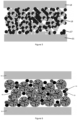
- a SOFC not of the invention Shown schematically in Figure 6 , is a SOFC not of the invention, the SOFC comprising an electrolyte 13 , an anode made up of a sintered impregnated PDC particles 19 and the ferritic stainless steel substrate 11 .
- the SOFC is shown in SEM micrographs of a cross-sectioned cell in Figure 7 . This has the advantage of very good REDOX stability and internal steam reforming activity relative to a conventional SOFC anode cermet because, without being bound by theory, it does not rely on the metallic phase for its mechanical stability.
- active metal-impregnated PDC particles are incorporated into conventional cermet anode structures, partially replacing the metallic/matrix phase.
- the presence of the contiguous metallic phase results in a greatly enhanced electronic conductivity, at the expense of some REDOX stability and catalytic activity for internal steam reforming.
- both of these properties are still enhanced by comparison with a conventional cermet anode.
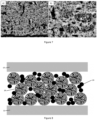
- FIG 8 This structure is shown schematically in Figure 8 , showing the electrolyte 13 , the steel substrate 11 , and the anode comprising impregnated PDC particles 19 , CGO 21 and metal 23 (the contiguous CGO and metal phase shown as particles to schematically illustrate the presence of both materials).
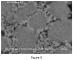
- An anode of this type is shown as an SEM cross section in Figure 9 .
- a standard cermet anode contains 42 wt% CGO, and 58 wt% a 90:10 mixture of NiO and CuO upon initial manufacture. It has been shown that reducing the NiO/CuO content in these structures results in enhanced mechanical and REDOX stability, at the expense of electrochemical performance and internal steam reforming activity. It has been demonstrated that a desirable combination of high electrochemical performance, high REDOX stability and high internal reforming activity may be achieved by maintaining the 42wt% CGO, but partially replacing the NiO/CuO content with impregnated PDC.
- the anode shown in Figure 9 has the composition CGO 42 wt%, impregnated PDC 33 wt% and NiO/CuO 25 wt%. This results in an anode only containing around 28wt% metal which has electrochemical performance comparable with a conventional cermet anode with 58 wt% metal. This reduction in metal content enhances the mechanical and REDOX stability of the anode.
- the active-metal impregnated PDC particles are incorporated into a matrix of a suitable electronically conductive ceramic.
- the porous conductive ceramic matrix provides the mechanical structure of the anode and provides a current collection path from the anode-electrolyte interface to the substrate. This is shown schematically in Figure 10, showing the electrolyte 13 , the impregnated PDC particles 19 , the conductive ceramic 25 (the ceramic matrix being schematically illustrated as particles) and the steel substrate 11 .
- Figure 11 shows an SEM cross section of PDC particles incorporated into a conductive ceramic matrix.
- suitable electronically conductive ceramic is limited to materials which are stable and electronically conductive in a reducing atmosphere at SOFC operational temperatures.
- Suitable materials include the perovskites La 0.75 Sr 0.25 CrO 3 (lanthanum strontium chromite, LSCr) and La 0.75 Sr 0.25 Mn 0.5 Cr 0.5 O 3 (Lanthanum strontium chromium manganite, LSCrM). Of these two materials LSCrM is favoured due to its greater sinterability relative to LSCr. It will be noted that the relative ratios of lanthanum and strontium on the A-site of the perovskite, and chromium and manganese on the B-site may be varied significantly.
- Other suitable materials include the doped strontium titanates. This has been found to be advantageous of demonstrating very high REDOX stability as the mechanical structure of the anode is made of fully REDOX stable ceramic.
- Table 1 shows a summary of testing data for the above described systems, and a comparison with standard anode cermets.
- the PDC was impregnated with 8 wt% nickel and 2 wt% cobalt, the cobalt being added to enhance sintering of the layer.
- SOFC power at 570°C and 0.75V/cell is measured in 56% H 2 / 44% N 2 fuel. It can be seen that the power output of the Embodiment is comparable with the standard anode, with somewhat lower power in the case of the PDC anode due to higher ohmic resistance in the anode as described previously.
- the overall and internal methane conversions are a measure of the catalytic activity of the anode for internal methane steam reforming. This is measured with a stack temperature of 610°C, with the stack being operated on partially steam reformed methane with a thermodynamic equilibrium temperature of 540°C, with a stack fuel utilisation of 65%.
- the overall methane conversion is the methane conversion between the reformer feed and the stack fuel outlet.
- the internal methane conversion is the percentage of the methane in the stack fuel feed converted within the stack.
- the reformate equilibrium of 540°C means that 55% of the methane fed to the system is converted externally, with the remainder converted within the stack.
- the fuel feed composition for these measurements are shown in Table 2.
- the methane conversion is calculated based on a measurement of the fuel gas composition leaving the stack using an infra-red gas analyser.
- Table 1 Summary of performance testing metrics Variant CGO / wt% PDC / wt% NiO/Cu O / wt% Mean cell power at 570°C, 0.75V / W REDOX stability Overall methane conversion / % Internal methane conversion / % PDC Anode 0 100 0 17.45 >184 cycles 93 84 Embodiment 42 33 25 20.54 >200 cycles 0.3 % overall performance change 93 84 Standard anode cermet 44 0 56 21.45 >200 cycles 1% overall performance change 91 80
- Table 2 Fuel gas composition for internal methane conversion measurements. Gas Mole % in stack gas feed Hydrogen 42.3 Steam 35.6 Carbon monoxide 2.7 Carbon dioxide 8.6 Methane 10.9
Landscapes
- Chemical & Material Sciences (AREA)
- Chemical Kinetics & Catalysis (AREA)
- Electrochemistry (AREA)
- General Chemical & Material Sciences (AREA)
- Engineering & Computer Science (AREA)
- Composite Materials (AREA)
- Materials Engineering (AREA)
- Manufacturing & Machinery (AREA)
- Ceramic Engineering (AREA)
- Life Sciences & Earth Sciences (AREA)
- Sustainable Energy (AREA)
- Sustainable Development (AREA)
- Inert Electrodes (AREA)
- Fuel Cell (AREA)
- Catalysts (AREA)
- Hydrogen, Water And Hydrids (AREA)
Claims (14)
- Anode für eine Festoxidbrennstoffzelle (SOFC), wobei die Anode umfasst:- eine Matrix (25), die ein dotiertes Metalloxid umfasst, und- einen Elektrokatalysator, der aus porösen Cermet-Teilchen (19) besteht, die in der Matrix dispergiert sind, wobei die porösen Teilchen ein Metallkatalysatormaterial (7) für die Dampfreformierung umfassen, das in den Poren (5) der porösen Teilchen eingeschlossen ist,- wobei die porösen Teilchen aus einem anderen Material als die Matrix (25) hergestellt sind, und wobei das Katalysatormaterial (7) für die Dampfreformierung ein Element umfasst, das aus der Gruppe ausgewählt ist, die aus Fe, Co, Ru, Ni, Rh, Pt, Pd oder einer Kombination davon besteht.
- Anode nach Anspruch 1, wobei das Dampfreformierungskatalysatormaterial (7) ausgewählt ist aus Fe, Co, Ni oder einer Kombination davon.
- Anode nach Anspruch 2, wobei das Dampfreformierungskatalysatormaterial (7) Nickel ist.
- Anode nach einem der vorhergehenden Ansprüche, wobei das dotierte Metalloxid ein elektrisch leitendes keramisches Material ist, das gegebenenfalls aus den Perowskiten Lanthan-Strontium-Chromit (LSCr), Lanthan-Strontium-Chrom-Manganit (LSCrM) und dotierten Strontiumtitanaten ausgewählt ist.
- Anode nach einem der vorhergehenden Ansprüche, wobei das dotierte Metalloxid ein mit seltenen Erden dotiertes Ceroxid ist, das gegebenenfalls ausgewählt ist aus: mit Gadolinium dotiertem Ceroxid (CGO), mit Samarium dotiertem Ceroxid oder Kombinationen davon.
- Anode nach einem der vorhergehenden Ansprüche, wobei die porösen Teilchen (19) Porengrößen von weniger als 1 µm haben, und wobei die porösen Teilchen Porengrößen von mehr als 1 nm haben.
- Anode nach einem der vorhergehenden Ansprüche, wobei die porösen Teilchen (19), die ein Dampfreformierungskatalysatormaterial (7) enthalten, im Bereich von 5 bis 70 Gew.-%, gegebenenfalls im Bereich von 10 bis 60 Gew.-%, bezogen auf das Gewicht der gesamten Anode, vorhanden sind.
- Anode nach Anspruch 3, wobei die porösen Teilchen (19) ein mit seltenen Erden dotiertes Ceroxid umfassen.
- Anode nach einem der vorhergehenden Ansprüche, wobei die porösen Teilchen (19) mit Praseodym dotiertes Ceroxid (PDC) umfassen.
- Anode nach einem der vorhergehenden Ansprüche, wobei die Matrix (25) ferner ein Dampfreformierungskatalysatormaterial (7) im Bereich von 5 bis 70 Gew.-% der gesamten Anode umfasst, wobei das Dampfreformierungskatalysatormaterial wahlweise aus Nickel und Nickeloxid ausgewählt ist.
- Zusammensetzung zur Herstellung der Anode nach einem der vorhergehenden Ansprüche, wobei die Zusammensetzung Folgendes umfasst:- einen Matrixvorläufer, der ein dotiertes Metalloxid umfasst, und einen Elektrokatalysator,- wobei der Elektrokatalysator poröse Cermet-Teilchen (19) umfasst, die ein Dampfreformierungskatalysatormaterial (7) enthalten, das in den Poren der Katalysatorteilchen eingeschlossen ist, wobei das Dampfreformierungskatalysatormaterial ein Element umfasst, das aus der Gruppe ausgewählt ist, die aus Fe, Co, Ru, Ni, Rh, Pt, Pd oder einer Kombination davon besteht.
- Verfahren zur Herstellung der Anode nach einem der Ansprüche 1 bis 10, das die folgenden Schritte umfasst:- i) Aufbringen einer Zusammensetzung nach Anspruch 11 auf ein Substrat und- ii) Sintern der Materialien der Zusammensetzung.
- Festoxidbrennstoffzelle mit der Anode nach einem der Ansprüche 1 bis 10.
- Festoxid-Brennstoffzelle nach Anspruch 13, wobei die Anode für eine Festoxid-Brennstoffzelle mit Metallträger ist und auf einem Metallträgersubstrat vorgesehen ist.
Applications Claiming Priority (2)
| Application Number | Priority Date | Filing Date | Title |
|---|---|---|---|
| GB1620848.0A GB2557344B (en) | 2016-12-08 | 2016-12-08 | Anode |
| PCT/GB2017/053681 WO2018104736A1 (en) | 2016-12-08 | 2017-12-07 | An anode for a solid oxide fuel cell |
Publications (3)
| Publication Number | Publication Date |
|---|---|
| EP3552263A1 EP3552263A1 (de) | 2019-10-16 |
| EP3552263B1 true EP3552263B1 (de) | 2024-12-25 |
| EP3552263C0 EP3552263C0 (de) | 2024-12-25 |
Family
ID=58222060
Family Applications (1)
| Application Number | Title | Priority Date | Filing Date |
|---|---|---|---|
| EP17817044.5A Active EP3552263B1 (de) | 2016-12-08 | 2017-12-07 | Anode für eine festkörperoxidbrennstoffzelle |
Country Status (9)
| Country | Link |
|---|---|
| US (1) | US11367888B2 (de) |
| EP (1) | EP3552263B1 (de) |
| JP (1) | JP7041678B2 (de) |
| KR (1) | KR102551984B1 (de) |
| CN (1) | CN110050373B (de) |
| CA (1) | CA3046161C (de) |
| GB (1) | GB2557344B (de) |
| RU (1) | RU2743000C2 (de) |
| WO (1) | WO2018104736A1 (de) |
Families Citing this family (7)
| Publication number | Priority date | Publication date | Assignee | Title |
|---|---|---|---|---|
| US12116278B2 (en) | 2018-12-27 | 2024-10-15 | Qatar Foundation For Education, Science And Community Development | Catalysts for converting carbon dioxide and methane to synthesis gas |
| DE102019200543A1 (de) * | 2019-01-17 | 2020-07-23 | Robert Bosch Gmbh | Verfahren zur Herstellung einer elektrochemischen Zelle |
| CN111261879A (zh) * | 2020-01-23 | 2020-06-09 | 同济大学 | 含分散助剂的催化剂浆料及制得的催化层和燃料电池电极 |
| CN115528259B (zh) * | 2021-06-24 | 2024-04-26 | 长春理工大学 | 一种铋离子修饰铁酸镨基固体氧化物燃料电池阳极材料及其制备方法 |
| EP4187651A1 (de) | 2021-11-29 | 2023-05-31 | Pietro Fiorentini S.P.A. | Elektrochemische vorrichtung |
| WO2024122791A1 (en) * | 2022-12-07 | 2024-06-13 | Samsung Electro-Mechanics Co., Ltd. | Metal-solid oxide composite, preparing method thereof, and solid oxide cell including the same |
| DE102023207910A1 (de) * | 2023-08-17 | 2025-02-20 | Forschungszentrum Jülich GmbH | Festoxidzelle mit nickelfreier Brennstoffelektrode |
Citations (1)
| Publication number | Priority date | Publication date | Assignee | Title |
|---|---|---|---|---|
| EP0996184A2 (de) * | 1998-10-19 | 2000-04-26 | Sofco | Hochleistungsanode für Festoxidbrennstoffzelle |
Family Cites Families (24)
| Publication number | Priority date | Publication date | Assignee | Title |
|---|---|---|---|---|
| JP2948373B2 (ja) * | 1991-09-06 | 1999-09-13 | 三菱重工業株式会社 | 固体電解質型燃料電池の燃料電極 |
| US5908713A (en) | 1997-09-22 | 1999-06-01 | Siemens Westinghouse Power Corporation | Sintered electrode for solid oxide fuel cells |
| US6793711B1 (en) | 1999-12-07 | 2004-09-21 | Eltron Research, Inc. | Mixed conducting membrane for carbon dioxide separation and partial oxidation reactions |
| RU2420833C2 (ru) * | 2003-11-14 | 2011-06-10 | Зи Юнивесити оф Экрон | Топливный элемент прямого электрохимического окисления (варианты) и способ выработки электроэнергии из твердофазного органического топлива (варианты) |
| JP4199691B2 (ja) * | 2004-03-25 | 2008-12-17 | 田中貴金属工業株式会社 | 触媒 |
| US20070015015A1 (en) * | 2005-07-12 | 2007-01-18 | Koji Hoshino | Solid oxide fuel cell |
| JP2007115536A (ja) * | 2005-10-20 | 2007-05-10 | Tokyo Electric Power Co Inc:The | 多孔質固体酸化物形燃料電池用電極の製造方法 |
| DE102006005194B4 (de) | 2006-02-02 | 2008-07-24 | Forschungszentrum Jülich GmbH | Protonen leitendes Schichtsystem und Herstellungsverfahren desselben |
| DE102006030393A1 (de) * | 2006-07-01 | 2008-01-03 | Forschungszentrum Jülich GmbH | Keramische Werkstoffkombination für eine Anode für eine Hochtemperatur-Brennstoffzelle |
| US8053142B2 (en) * | 2006-11-30 | 2011-11-08 | Atomic Energy Council-Institute Of Nuclear Energy Research | Nanostructured composite anode with nano gas channels and atmosphere plasma spray manufacturing method thereof |
| DE602006020310D1 (de) | 2006-12-01 | 2011-04-07 | Atomic Energy Council | Nanostrukturierte Verbundanode mit Nanogaskanälen und Atmosphärenplasmasprayverfahren zu deren Herstellung |
| US8435683B2 (en) | 2007-07-19 | 2013-05-07 | Cp Sofc Ip, Llc | Internal reforming solid oxide fuel cells |
| EP2254180A1 (de) * | 2007-08-31 | 2010-11-24 | Technical University of Denmark | Ceria- und Strontium-Titanat-basierte Elektroden |
| CN101733089B (zh) | 2008-11-25 | 2012-12-12 | 中国科学院物理研究所 | 一种制备氢气的催化剂及其制备方法和应用 |
| JP5439959B2 (ja) * | 2009-06-08 | 2014-03-12 | 東京電力株式会社 | 固体酸化物形燃料電池用電極及び固体酸化物形燃料電池用セル |
| US8617763B2 (en) * | 2009-08-12 | 2013-12-31 | Bloom Energy Corporation | Internal reforming anode for solid oxide fuel cells |
| JP2013014820A (ja) * | 2011-07-06 | 2013-01-24 | Toshiba Corp | 燃料ガス改質用電解セル、及び電解セルを利用した改質ガスの生成方法 |
| TW201347289A (zh) * | 2012-05-04 | 2013-11-16 | Inst Nuclear Energy Res Atomic Energy Council | 高穩定高效率固態氧化物燃料電池陽極結構及其製造方法 |
| US9496559B2 (en) * | 2012-08-07 | 2016-11-15 | Atomic Energy Council-Institute Of Nuclear Energy Research | Method for manufacturing solid oxide fuel cell anode with high stability and high efficiency |
| JP6191429B2 (ja) * | 2012-12-10 | 2017-09-06 | Toto株式会社 | 固体酸化物形燃料電池セル |
| JP6332610B2 (ja) | 2013-03-28 | 2018-05-30 | Toto株式会社 | 固体酸化物形燃料電池セル及びその製造方法 |
| CN103977808B (zh) * | 2014-05-30 | 2016-08-24 | 厦门大学 | 一种镍铈催化剂及其制备方法与应用 |
| JP6725994B2 (ja) * | 2015-03-03 | 2020-07-22 | 株式会社豊田中央研究所 | 水蒸気改質触媒、それを用いた水蒸気改質方法、及び水蒸気改質反応装置 |
| CN105024085A (zh) * | 2015-06-04 | 2015-11-04 | 沈阳航空航天大学 | 一种针状分布的固体氧化物燃料电池阳极制备工艺方法 |
-
2016
- 2016-12-08 GB GB1620848.0A patent/GB2557344B/en active Active
-
2017
- 2017-12-07 CA CA3046161A patent/CA3046161C/en active Active
- 2017-12-07 WO PCT/GB2017/053681 patent/WO2018104736A1/en not_active Ceased
- 2017-12-07 KR KR1020197019310A patent/KR102551984B1/ko active Active
- 2017-12-07 CN CN201780076369.2A patent/CN110050373B/zh active Active
- 2017-12-07 EP EP17817044.5A patent/EP3552263B1/de active Active
- 2017-12-07 JP JP2019530760A patent/JP7041678B2/ja active Active
- 2017-12-07 US US16/467,926 patent/US11367888B2/en active Active
- 2017-12-07 RU RU2019120050A patent/RU2743000C2/ru active
Patent Citations (1)
| Publication number | Priority date | Publication date | Assignee | Title |
|---|---|---|---|---|
| EP0996184A2 (de) * | 1998-10-19 | 2000-04-26 | Sofco | Hochleistungsanode für Festoxidbrennstoffzelle |
Non-Patent Citations (9)
| Title |
|---|
| "Doctoral Dissertation, West Virginia University", 1 January 2019, article OZMEN OZCAN: "Investigation of Nano-ceria Catalyst Infiltration of Solid Oxide Fuel Cell (SOFC) Electrodes Using Bio-Inspired Catechol Surfactants ", XP093320859, DOI: 10.33915/etd.7378 |
| ALIGUL BUYUKAKSOY, SANOOP P. KAMMAMPATA, AND VIOLA I. BIRSS: "Effect of porous YSZ scaffold microstructure on the long-term performance of infiltrated Ni-YSZ anodes", JOURNAL OF POWER SOURCES, vol. 287, 2015, pages 349 - 358, XP029158124, DOI: 10.1016/j.jpowsour.2015.04.072 |
| H. MORI, C. WEN, J. OTOMO, K. EGUCHI, H. TAKAHASHI: "Investigation of the interaction between NiO and yttria- stabilized zirconia(YSZ) in the NiO/YSZ composite by temperature programmed reduction technique", APPL CATAL A GEN, vol. 245, 2003, pages 79 - 85, XP004425607, DOI: 10.1016/S0926-860X(02)00634-8 |
| JIANG, S.P.: "A review of wet impregnation-An alternative method for the fabrication of high performance and nano-structured electrodes of solid oxide fuel cells", MATERIALS SCIENCE, ELSEVIER, AMSTERDAM, NL, vol. 418, no. 1-2, 25 February 2006 (2006-02-25), AMSTERDAM, NL, pages 199 - 210, XP025098518, ISSN: 0921-5093, DOI: 10.1016/j.msea.2005.11.052 |
| MARTINS R. F., BRANT M. C., DOMINGUES R. Z., MATENCIO T.: "NiO/YSZ Composites for SOFC: Synthesis and Characterization", ASME 2006 FOURTH INTERNATIONAL CONFERENCE ON FUEL CELL SCIENCE, ENGINEERING AND TECHNOLOGY, PARTS A AND B, ASMEDC, 1 January 2006 (2006-01-01) - 21 June 2006 (2006-06-21), pages 621 - 622, XP093320887, ISBN: 978-0-7918-3780-1, DOI: 10.1115/FUELCELL2006-97146 |
| R.F. MARTINS, M.C. BRANT, R.Z. DOMINGUES, R.M. PANIAGO, K. SAPAG, T. MATENCIO: "Synthesis and characterization of NiO-YSZ for SOFCs", MATER RES BULL, vol. 44, 2009, pages 451 - 456, XP025839143, DOI: 10.1016/j.materresbull.2008.04.017 |
| SMIRNOVA ALEVTINA, SADYKOV VLADISLAV, MEZENTSEVA NATALIA, BUNINA RIMMA, PILIPENKO V. V., ALIKINA GALINA, KRIEGER TAMARA A., BOBROV: "Design and Testing of Structured Catalysts for Internal Reforming of CH 4 in Intermediate Temperature Solid Oxide Fuel Cells (IT SOFC)", ECS TRANSACTIONS, ELECTROCHEMICAL SOCIETY, US, vol. 35, no. 1, 25 April 2011 (2011-04-25), US , pages 2771 - 2780, XP093320865, ISSN: 1938-5862, DOI: 10.1149/1.3570276 |
| V. SADYKOV, N. MEZENTSEVA, G. ALIKINA, R. BUNINA, V. ROGOV, T. KRIEGER, S. BELOCHAPKINE, J. ROSS: "Composite catalytic materials for steam reforming of methane and oxygenates: Combinatorial synthesis, characterization and performance", CATAL TODAY, vol. 145, 2009, pages 127 - 137, XP026159265, DOI: 10.1016/j.cattod.2008.04.034 |
| V.A. SADYKOV, N. V. MEZENTSEVA, R. V. BUNINA, G.M. ALIKINA, A.I. LUKASHEVICH, T.S. KHARLAMOVA, V.A. ROGOV, V.I. ZAIKOVSKII,: "Effect of complex oxide promoters and Pd on activity and stability of Ni/YSZ (ScSZ) cermets as anode materials for IT SOFC", CATAL TODAY, vol. 131, 2008, pages 226 - 237, XP022432534, DOI: 10.1016/j.cattod.2007.10.064 |
Also Published As
| Publication number | Publication date |
|---|---|
| JP2020517044A (ja) | 2020-06-11 |
| JP7041678B2 (ja) | 2022-03-24 |
| US20200075979A1 (en) | 2020-03-05 |
| EP3552263A1 (de) | 2019-10-16 |
| RU2019120050A3 (de) | 2021-01-11 |
| RU2743000C2 (ru) | 2021-02-12 |
| WO2018104736A1 (en) | 2018-06-14 |
| RU2019120050A (ru) | 2021-01-11 |
| GB2557344A (en) | 2018-06-20 |
| US11367888B2 (en) | 2022-06-21 |
| GB201620848D0 (en) | 2017-01-25 |
| CA3046161C (en) | 2024-01-02 |
| KR20190087628A (ko) | 2019-07-24 |
| CA3046161A1 (en) | 2018-06-14 |
| KR102551984B1 (ko) | 2023-07-06 |
| GB2557344B (en) | 2021-05-19 |
| CN110050373B (zh) | 2022-11-25 |
| EP3552263C0 (de) | 2024-12-25 |
| CN110050373A (zh) | 2019-07-23 |
Similar Documents
| Publication | Publication Date | Title |
|---|---|---|
| EP3552263B1 (de) | Anode für eine festkörperoxidbrennstoffzelle | |
| US8252478B2 (en) | Redox-stable anode | |
| CN112447982B (zh) | 固体氧化物型燃料电池及其制造方法 | |
| US20140170532A1 (en) | Solid-oxide fuel cell | |
| KR20110116213A (ko) | 3원계 백금 합금 촉매 | |
| KR20100057619A (ko) | 내부 개질 고체 옥사이드 연료 전지 | |
| WO2017030023A1 (ja) | セル構造体の製造方法 | |
| US20020098406A1 (en) | Redox solid oxide fuel cell | |
| JP7484048B2 (ja) | 固体酸化物型燃料電池およびその製造方法 | |
| WO2017013868A1 (ja) | 固体酸化物形燃料電池、および電解質層-アノード接合体の製造方法 | |
| JP2015506536A (ja) | 燃料電池 | |
| KR20100093957A (ko) | 연료극 물질, 그의 제조방법 및 이를 포함하는 고체 산화물연료전지 | |
| JP7377051B2 (ja) | 固体酸化物型燃料電池およびその製造方法 | |
| CN111613798B (zh) | 燃料电池及其制造方法 | |
| EP4158706B1 (de) | Direkt-ammoniak gespeiste brennstoffzelle und deren herstellungsverfahren | |
| JP7629444B2 (ja) | 固体酸化物型燃料電池、固体酸化物型燃料電池スタック、及び固体酸化物型燃料電池の製造方法 | |
| EP3211703B1 (de) | Brennstoffzelle | |
| US20120189944A1 (en) | Solid electrolyte for solid oxide fuel cell, and solid oxide fuel cell including the solid electrolyte | |
| KR101218602B1 (ko) | 은 나노입자를 포함하는 저온 작동 고체산화물 연료전지 제조방법 및 이에 의해 제조된 고체산화물 연료전지 | |
| JP2023071348A (ja) | 固体酸化物型燃料電池およびその製造方法 | |
| CN114175318B (zh) | 燃料电池用催化剂层、其制造方法以及具备其的燃料电池 | |
| WO2024135170A1 (ja) | 固体酸化物型燃料電池およびその製造方法 | |
| WO2024135343A1 (ja) | 固体酸化物型燃料電池およびその製造方法 | |
| JP2024083913A (ja) | 固体酸化物型燃料電池およびその製造方法 |
Legal Events
| Date | Code | Title | Description |
|---|---|---|---|
| STAA | Information on the status of an ep patent application or granted ep patent |
Free format text: STATUS: UNKNOWN |
|
| STAA | Information on the status of an ep patent application or granted ep patent |
Free format text: STATUS: THE INTERNATIONAL PUBLICATION HAS BEEN MADE |
|
| PUAI | Public reference made under article 153(3) epc to a published international application that has entered the european phase |
Free format text: ORIGINAL CODE: 0009012 |
|
| STAA | Information on the status of an ep patent application or granted ep patent |
Free format text: STATUS: REQUEST FOR EXAMINATION WAS MADE |
|
| 17P | Request for examination filed |
Effective date: 20190702 |
|
| AK | Designated contracting states |
Kind code of ref document: A1 Designated state(s): AL AT BE BG CH CY CZ DE DK EE ES FI FR GB GR HR HU IE IS IT LI LT LU LV MC MK MT NL NO PL PT RO RS SE SI SK SM TR |
|
| AX | Request for extension of the european patent |
Extension state: BA ME |
|
| DAV | Request for validation of the european patent (deleted) | ||
| DAX | Request for extension of the european patent (deleted) | ||
| STAA | Information on the status of an ep patent application or granted ep patent |
Free format text: STATUS: EXAMINATION IS IN PROGRESS |
|
| 17Q | First examination report despatched |
Effective date: 20200408 |
|
| P01 | Opt-out of the competence of the unified patent court (upc) registered |
Effective date: 20230525 |
|
| GRAP | Despatch of communication of intention to grant a patent |
Free format text: ORIGINAL CODE: EPIDOSNIGR1 |
|
| STAA | Information on the status of an ep patent application or granted ep patent |
Free format text: STATUS: GRANT OF PATENT IS INTENDED |
|
| INTG | Intention to grant announced |
Effective date: 20240710 |
|
| RBV | Designated contracting states (corrected) |
Designated state(s): AL AT BE BG CH CY CZ DE DK EE ES FI FR GR HR HU IE IS IT LI LT LU LV MC MK MT NL NO PL PT RO RS SE SI SK SM TR |
|
| GRAS | Grant fee paid |
Free format text: ORIGINAL CODE: EPIDOSNIGR3 |
|
| GRAA | (expected) grant |
Free format text: ORIGINAL CODE: 0009210 |
|
| STAA | Information on the status of an ep patent application or granted ep patent |
Free format text: STATUS: THE PATENT HAS BEEN GRANTED |
|
| AK | Designated contracting states |
Kind code of ref document: B1 Designated state(s): AL AT BE BG CH CY CZ DE DK EE ES FI FR GR HR HU IE IS IT LI LT LU LV MC MK MT NL NO PL PT RO RS SE SI SK SM TR |
|
| REG | Reference to a national code |
Ref country code: CH Ref legal event code: EP |
|
| REG | Reference to a national code |
Ref country code: DE Ref legal event code: R096 Ref document number: 602017086984 Country of ref document: DE |
|
| REG | Reference to a national code |
Ref country code: IE Ref legal event code: FG4D |
|
| U01 | Request for unitary effect filed |
Effective date: 20250103 |
|
| P04 | Withdrawal of opt-out of the competence of the unified patent court (upc) registered |
Free format text: CASE NUMBER: APP_1895/2025 Effective date: 20250111 |
|
| U07 | Unitary effect registered |
Designated state(s): AT BE BG DE DK EE FI FR IT LT LU LV MT NL PT RO SE SI Effective date: 20250115 |
|
| PG25 | Lapsed in a contracting state [announced via postgrant information from national office to epo] |
Ref country code: HR Free format text: LAPSE BECAUSE OF FAILURE TO SUBMIT A TRANSLATION OF THE DESCRIPTION OR TO PAY THE FEE WITHIN THE PRESCRIBED TIME-LIMIT Effective date: 20241225 |
|
| PG25 | Lapsed in a contracting state [announced via postgrant information from national office to epo] |
Ref country code: NO Free format text: LAPSE BECAUSE OF FAILURE TO SUBMIT A TRANSLATION OF THE DESCRIPTION OR TO PAY THE FEE WITHIN THE PRESCRIBED TIME-LIMIT Effective date: 20250325 |
|
| PG25 | Lapsed in a contracting state [announced via postgrant information from national office to epo] |
Ref country code: GR Free format text: LAPSE BECAUSE OF FAILURE TO SUBMIT A TRANSLATION OF THE DESCRIPTION OR TO PAY THE FEE WITHIN THE PRESCRIBED TIME-LIMIT Effective date: 20250326 |
|
| PG25 | Lapsed in a contracting state [announced via postgrant information from national office to epo] |
Ref country code: RS Free format text: LAPSE BECAUSE OF FAILURE TO SUBMIT A TRANSLATION OF THE DESCRIPTION OR TO PAY THE FEE WITHIN THE PRESCRIBED TIME-LIMIT Effective date: 20250325 |
|
| PG25 | Lapsed in a contracting state [announced via postgrant information from national office to epo] |
Ref country code: SM Free format text: LAPSE BECAUSE OF FAILURE TO SUBMIT A TRANSLATION OF THE DESCRIPTION OR TO PAY THE FEE WITHIN THE PRESCRIBED TIME-LIMIT Effective date: 20241225 |
|
| PG25 | Lapsed in a contracting state [announced via postgrant information from national office to epo] |
Ref country code: PL Free format text: LAPSE BECAUSE OF FAILURE TO SUBMIT A TRANSLATION OF THE DESCRIPTION OR TO PAY THE FEE WITHIN THE PRESCRIBED TIME-LIMIT Effective date: 20241225 |
|
| PG25 | Lapsed in a contracting state [announced via postgrant information from national office to epo] |
Ref country code: ES Free format text: LAPSE BECAUSE OF FAILURE TO SUBMIT A TRANSLATION OF THE DESCRIPTION OR TO PAY THE FEE WITHIN THE PRESCRIBED TIME-LIMIT Effective date: 20241225 |
|
| PG25 | Lapsed in a contracting state [announced via postgrant information from national office to epo] |
Ref country code: IS Free format text: LAPSE BECAUSE OF FAILURE TO SUBMIT A TRANSLATION OF THE DESCRIPTION OR TO PAY THE FEE WITHIN THE PRESCRIBED TIME-LIMIT Effective date: 20250425 |
|
| PG25 | Lapsed in a contracting state [announced via postgrant information from national office to epo] |
Ref country code: SK Free format text: LAPSE BECAUSE OF FAILURE TO SUBMIT A TRANSLATION OF THE DESCRIPTION OR TO PAY THE FEE WITHIN THE PRESCRIBED TIME-LIMIT Effective date: 20241225 |
|
| PG25 | Lapsed in a contracting state [announced via postgrant information from national office to epo] |
Ref country code: CZ Free format text: LAPSE BECAUSE OF FAILURE TO SUBMIT A TRANSLATION OF THE DESCRIPTION OR TO PAY THE FEE WITHIN THE PRESCRIBED TIME-LIMIT Effective date: 20241225 |
|
| PLAZ | Examination of admissibility of opposition: despatch of communication + time limit |
Free format text: ORIGINAL CODE: EPIDOSNOPE2 |
|
| PLBI | Opposition filed |
Free format text: ORIGINAL CODE: 0009260 |
|
| 26 | Opposition filed |
Opponent name: ELCOGEN OY Effective date: 20250924 |
|
| U20 | Renewal fee for the european patent with unitary effect paid |
Year of fee payment: 9 Effective date: 20251110 |