EP3552061B1 - Uhrglas mit lumineszierendem element - Google Patents
Uhrglas mit lumineszierendem element Download PDFInfo
- Publication number
- EP3552061B1 EP3552061B1 EP17800764.7A EP17800764A EP3552061B1 EP 3552061 B1 EP3552061 B1 EP 3552061B1 EP 17800764 A EP17800764 A EP 17800764A EP 3552061 B1 EP3552061 B1 EP 3552061B1
- Authority
- EP
- European Patent Office
- Prior art keywords
- glass
- watch
- luminizing
- carrier
- elements
- Prior art date
- Legal status (The legal status is an assumption and is not a legal conclusion. Google has not performed a legal analysis and makes no representation as to the accuracy of the status listed.)
- Active
Links
Images

Classifications
-
- G—PHYSICS
- G04—HOROLOGY
- G04B—MECHANICALLY-DRIVEN CLOCKS OR WATCHES; MECHANICAL PARTS OF CLOCKS OR WATCHES IN GENERAL; TIME PIECES USING THE POSITION OF THE SUN, MOON OR STARS
- G04B19/00—Indicating the time by visual means
- G04B19/30—Illumination of dials or hands
-
- G—PHYSICS
- G04—HOROLOGY
- G04B—MECHANICALLY-DRIVEN CLOCKS OR WATCHES; MECHANICAL PARTS OF CLOCKS OR WATCHES IN GENERAL; TIME PIECES USING THE POSITION OF THE SUN, MOON OR STARS
- G04B19/00—Indicating the time by visual means
- G04B19/06—Dials
- G04B19/12—Selection of materials for dials or graduations markings
-
- G—PHYSICS
- G04—HOROLOGY
- G04B—MECHANICALLY-DRIVEN CLOCKS OR WATCHES; MECHANICAL PARTS OF CLOCKS OR WATCHES IN GENERAL; TIME PIECES USING THE POSITION OF THE SUN, MOON OR STARS
- G04B19/00—Indicating the time by visual means
- G04B19/30—Illumination of dials or hands
- G04B19/32—Illumination of dials or hands by luminescent substances
-
- G—PHYSICS
- G04—HOROLOGY
- G04B—MECHANICALLY-DRIVEN CLOCKS OR WATCHES; MECHANICAL PARTS OF CLOCKS OR WATCHES IN GENERAL; TIME PIECES USING THE POSITION OF THE SUN, MOON OR STARS
- G04B39/00—Watch crystals; Fastening or sealing of crystals; Clock glasses
Definitions
- the invention relates to a watch glass with luminescent elements.
- Dials with self-illuminating, fluorescent luminous dots are well known.
- Associated hands that are filled with self-illuminating fluorescent material are also previously known.
- the luminous dots on the dial and the self-luminous hands ensure that the wearer of the watch can read the time on their watch even at night without additional light.
- the DE 10 2015 204613 A1 discloses a method for producing a watch glass in which at least one diamond or gemstone or other gemstone is embedded.
- the method includes the steps of providing a carrier glass, providing a cover glass, introducing at least one recess into the carrier glass, providing at least one diamond, gemstone or other gemstone, inserting the at least one diamond, gemstone or gemstone into the at least a recess in the carrier glass, placing the cover glass on the carrier glass, and connecting the cover glass to the carrier glass in such a way that an airtight connection point is created between the cover glass and the carrier glass, which is subject to a suction cup effect.
- the DE 10 2015 204613 A1 also relates to a watch glass which is produced according to the process and a watch which is provided with such a watch glass.
- the EP 2 477 083 A1 discloses a clock having a base plate having at least one row of small lights for indicating the hours and a row of small lights for indicating the minutes, and an electrical or electronic controller for controlling the lights for indicating the hours and minutes.
- the DE 880 071 C reveals a watch glass with recesses filled with glowing powder.
- a watch glass which comprises a cover glass, a carrier glass which is connected to the cover glass to form a glass unit, and a luminescent element which is introduced into the glass unit.
- the present invention relocates the placement of the luminous material in the form of a luminescent element into the watch glass. This ensures that when used of the watch glass of a watch, the self-illuminating luminous material emits its light rays directly to the viewer, thus making a time division clearly visible even in the dark or at night. On the other hand, the luminous material also emits its light in the opposite direction, into the interior of the watch, where the dial and the hands are located. The luminescent element thus illuminates both the hands and the dial, which are arranged under the watch glass.
- the hands which are free of luminous material, can be freely designed.
- other elements such as the numbers on the dial, etc., can also be selected without compromising on design and do not have any luminous material. This makes it possible to reduce the overall amount of luminous material where the luminous material interferes, namely on the dial and the hand(s). There it is reduced to the value zero.
- an improved pattern can be achieved in terms of the distribution of the elements in the watch glass, which in turn leads to an improved appearance of the watch glass or watch.
- the great advantage of the invention is that the luminescent element not only shines back at the viewer and is therefore seen itself. Rather, the luminescent element itself becomes an illuminator for the entire watch.
- the luminescent element doesn't just want to be “seen”, it wants to illuminate.
- the dial and hands do not light up, they are illuminated as if during the day or with external lighting. This is achieved because the luminescent element is integrated into the watch glass above the interior of the dial and the hands.
- the cover glass is to be understood as a first glass and the carrier glass as a second glass.
- the cover glass corresponds in particular to the glass which faces a viewer or faces away from the bottom of a watch case.
- the carrier glass corresponds in particular to the glass that faces away from an observer or faces the bottom of the watch case.
- Luminescent means that the element does not supply energy supplied from outside, for example from the sun, in whole or in part to its thermal energy, but is put into an excited state by the absorbed energy and emits light. If there is no activation process between the absorption of energy and the emission, then it is called fluorescence. When an excited intermediate state can "store" energy for a certain period of time, it is called phosphorescence.
- fluorescence a very short afterglow as a direct consequence and side effect of the excitation
- phosphorescence means a longer afterglow after excitation.
- the term “luminescent” or “luminescence” serves as a generic term and includes the sub-terms “fluorescence” and “phosphorescence”.
- At least one recess is provided in the watch glass, in which the luminescent element is arranged, the recess being formed in the cover glass and/or in the carrier glass.
- the recess is particularly preferably formed completely in the carrier glass.
- the luminescent element is therefore closer to a dial and the hands of a watch that has the watch glass described. This increases the intensity of the illumination of an area of the dial illuminated by the luminescent element.
- the recess can preferably be formed in the carrier glass. This means that a larger area of the dial can be illuminated by the luminescent element.
- Another advantage of a recess with luminescent material in the carrier glass is that the cover glass can then be free of recesses. This makes it easier to use sapphire glass as a cover glass, which is much more difficult to provide with a recess than the softer mineral glass of the carrier glass.
- the use of sapphire glass as a cover glass or as a finish to the watch glass on the outside is advisable, as the scratch-resistant sapphire glass is preferred for high-quality watches.
- the luminescent element is arranged centrally in the glass unit made of the carrier glass and the cover glass in the direction of the thickness of the glass unit.
- the luminescent element is therefore preferably positioned centrally in the glass unit in a direction perpendicular to the glass unit or to the larger surface of the glass unit.
- the luminescent element can preferably be designed as a gemstone, in particular diamond, and/or an index and/or time marking element, the gemstone, the index and the time marking element having luminescent properties.
- the entire recess is filled by the luminescent element.
- the luminescent element There is essentially no air in the recess. This means that light refraction that would otherwise occur at the boundary between air and the luminescent element can be avoided. This means that no light is lost or scattered due to such refraction.
- the luminescent element only partially occupies the recess. This makes it easier to introduce the luminescent element into the recess.
- the luminescent element designed as a fluorescent gemstone, in particular a fluorescent diamond, for example brilliant cut, is provided.
- the luminescent element does not take up the entire recess.
- Fluorescent gemstones preferably natural fluorescent diamonds, are used, and at least one black light LED is installed in the interior of the watch, which illuminates the fluorescent diamonds from below and causes them to fluoresce.
- a black light LED is also provided when luminescent elements other than fluorescent gemstones are used.
- an intermediate layer is provided between the cover glass and the carrier glass.
- the intermediate layer preferably comprises a self-crosslinking film, in particular polymer film and/or adhesive film, a silicone layer and/or an adhesive which is in particular UV-curable.
- the luminescent element can preferably be arranged in the intermediate layer.
- the luminescent element is positioned completely in the intermediate layer.
- a recess in the cover glass and/or in the carrier glass can be dispensed with.
- a thickness of the luminescent element is smaller than a thickness of the intermediate layer.
- a plurality of luminescent elements are preferably provided in the watch glass, the elements being arranged in the glass unit in a circumferential direction of the glass unit.
- the luminescent elements lie on a circle in the glass unit.
- the recess and/or the luminescent element are preferably designed and/or arranged in such a way that when the luminescent element lights up, light can emerge from at least 50% of an area of the underside of the carrier glass.
- the light will initially emerge from the luminescence upwards. Daylight or a lighting medium that stimulates luminescence will first stimulate the upper layers of the luminous material and these will then increasingly shine back into the viewer's eye. In this case, the luminous material then passes on the energy downwards, in the form of light, which then stimulates the deeper layers of the luminous material.
- luminescent element in the Phrase "Light emerges from X% of a surface” also includes a variety of luminescent ones elements is to be understood. In other words, the above statement about the percentage applies even if a large number of luminescent elements are provided.
- Another advantage of positioning the luminous substance (luminescent elements) in the watch glass is that the light output of this substance is significantly optimized. If the luminous material is attached to the bottom of the interior of the clock, i.e. on the dial or on the hands, then only the light that radiates upwards, i.e. towards the viewer of the clock, has an effect. The light that radiates in the opposite direction, i.e. onto the dial or the hands on which the luminous material is placed, is lost to the viewer. Since in the present invention all the material surrounding the luminescent element or elements is transparent, there is an almost 100% yield of the emitted light. In this way, the effect of the luminous material (regardless of whether it is a chemical substance or a fluorescent gemstone) can be significantly optimized.
- the invention further relates to a watch with a watch glass described above.
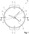
- the Fig. 1 shows a watch 10 in the form of a wristwatch with a housing 11 and a watch glass 1 according to the invention, which is arranged in the housing 11.
- the housing 11 and the watch glass 1 are circular, but can have any other shape such as. B. a rectangle, a polygon, etc. have.
- the clock 10 also has a dial 12, which is designed, for example, as a gold leaf, as well as three hands 13 for displaying the hours, minutes and seconds, and two connections for a bracelet 14.
- the clock 10 includes a clockwork 7 for operating the hands 13.
- clocks are also conceivable that do not have 3, but only 2 hands.
- the watch glass 1 is provided with luminescent elements 5.
- luminescent elements 5 In particular, four luminescent elements 5 with a constant radius in the circumferential direction are arranged in the watch glass 1 at the same distance from one another.
- the position and the number of the luminescent elements 5 can be chosen arbitrarily depending on the watch design. For example, it is also possible to install either just one luminescent element or two or twelve luminescent elements in the watch glass 1.
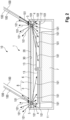
- the Fig. 2 is a simplified, schematic view of a section AA of the watch glass 1 of Fig. 1 .
- the watch glass 1 has a carrier glass 2 and a cover glass 3.
- the carrier glass 2 and the cover glass 3 are preferably made of different types of glass.
- the carrier glass 2 is a mineral glass and the cover glass 3 is a sapphire glass.
- Other types of glass can also be used.
- the carrier glass 2 can be made of sapphire glass or a polymer product, for example.
- B. plexiglass, and / or the cover glass 3 can be made of mineral glass or plexiglass.
- Recesses 4 are formed in the carrier glass 2 and serve to accommodate the luminescent elements 5. In Figure 2 two such recesses 4 can be seen. The recesses 4 are preferably formed exclusively in the carrier glass 2.
- the corresponding luminescent element 5 is preferably completely arranged in each recess 4. This means that the luminescent element 5 preferably completely fills the associated recess 4.
- the recesses 4 are not completely, i.e. only partially, filled by the luminescent elements 5. This is particularly the case when fluorescent gemstones, particularly preferably fluorescent diamonds, for example brilliant cut, are used as the luminescent elements 5.
- the cover glass 3 and the carrier glass 2 are in particular circular and have the same diameter.
- the glasses 2, 3 differ in their thickness, with the cover glass 3 preferably having a thinner shape. But it is also possible for the two glasses 2, 3 to have the same thickness.
- an inner surface 20 of the carrier glass 2 and an inner surface 30 of the cover glass 3 are flat at the contact point of the two glasses 2, 3. According to an alternative embodiment, the inner surfaces 20, 30 can also be curved in the same and complementary manner.
- the cover glass 3 and the carrier glass 2 are connected to one another via a connecting intermediate layer 6 (connecting layer).
- the intermediate layer 6 can in particular as Adhesive film, laminating film, glue or another bonding compound can be formed.
- the intermediate layer 6 is arranged between the cover glass 3 and the carrier glass 2. A seamless, airtight connection thus results between the cover glass 3 and the carrier glass 2.
- the luminescent elements 5 can advantageously store light (arrows 100), in particular sunlight, when they are illuminated and release it again in the dark (arrows 101).
- the cover glass 3, the carrier glass 2 and the luminescent elements 5 are first provided.
- the recesses 4 for receiving the luminescent elements 5 are introduced into the carrier glass 2.
- the luminescent elements 5 are then inserted into the recesses 4.
- the intermediate layer 6 is applied to the carrier glass 2.
- the intermediate layer 6 can, as already described, be a self-crosslinking polymer film, a thin silicone layer, a UV-curing adhesive or another connecting material.
- the cover glass 3 is applied to the intermediate layer 6.
- the intermediate layer 6 is preferably heated under vacuum and at the same time under pressure from above and below.
- the carrier glass 2 and the cover glass 3 are connected to one another in such a way that the luminescent elements 5 are firmly integrated between the two glasses 2, 3 and that the entire structure becomes a solid glass unit 8.
- the second embodiment of Fig. 3 differs from the first embodiment of Figures 1 and 2 basically because there are no recesses in the watch glass 1. Instead, the luminescent elements 5 are preferably embedded in the intermediate layer 6. In particular, the luminescent elements 5 lie on the inside 20 of the carrier glass 2.
- the manufacturing process of the watch glass 1 according to the second exemplary embodiment corresponds to the manufacturing process of the watch glass 1 according to the first exemplary embodiment, except for the steps of introducing recesses into the carrier glass 2 and inserting the luminescent elements 5 into recesses.
- the luminescent elements 5 are placed on the carrier glass 2.
- the intermediate layer 6 is then applied to the carrier glass 2 or the luminescent elements 5.
- the watch glass 1 comprises two glasses (cover glass and carrier glass). However, it is possible for the watch glass 1 to have several glasses, with successive glasses being connected to one another, in particular by an intermediate layer.
Landscapes
- Physics & Mathematics (AREA)
- General Physics & Mathematics (AREA)
- Electric Clocks (AREA)
- Illuminated Signs And Luminous Advertising (AREA)
Description
- Die Erfindung betrifft ein Uhrglas mit lumineszierenden Elementen.
- Zifferblätter mit selbstleuchtenden, fluoreszierenden Leuchtpunkten sind hinlänglich bekannt. Ebenso sind dazugehörige Zeiger, die mit selbstleuchtender fluoreszierender Masse angefüllt, vorbekannt. Die Leuchtpunkte auf dem Zifferblatt und die selbstleuchtenden Zeiger zielen darauf ab, dass der Träger der Uhr auch bei Nacht ohne zusätzliches Licht die Zeit auf seiner Uhr ablesen kann.
- Die bisherigen Methoden einer selbstleuchtenden Ziffern- und Zeiger-Anzeige durch fluoreszierende Substanzen in, oder neben den Ziffern, und auf oder in den Zeigern, haben aber einen entscheidenden Design-Nachteil. Die Zeiger müssen entsprechend dick oder breit sein, um die Leuchtmasse beherbergen zu können. Ebenso müssen sich die Ziffern der Uhr den Platz mit den Leuchtpunkten teilen, oder die ganzen Ziffern müssen so breit sein, dass diese mit Leuchtmasse angefüllt werden können.
- Im Resultat kollidiert ein filigranes, kunstvoll gestaltetes Design einer Uhr immer mit den Platzanforderungen der Leuchtmasse und wird dadurch eigentlich unmöglich gemacht.
- Die
DE 10 2015 204613 A1 offenbart ein Verfahren zum Herstellen eines Uhrglases, in welchem mindestens ein Diamant oder Edelstein oder sonstiger Schmuckstein eingebettet ist. Das Verfahren umfasst die Schritte des Bereitstellens eines Trägerglases, des Bereitstellens eines Deckglases, des Einbringens von mindestens einer Ausnehmung in das Trägerglas, des Bereitstellens von mindestens einem Diamanten, Edelstein oder sonstigen Schmuckstein, des Einsetzens des mindestens einen Diamanten, Edelsteins oder Schmucksteins in die mindestens eine Ausnehmung des Trägerglases, des Auflegens des Deckglases auf das Trägerglas, und des Verbindens des Deckglases mit dem Trägerglas derart, dass eine luftdichte Verbindungstelle zwischen dem Deckglas und den Trägerglas entsteht, welche einem Saugnapfeffekt unterliegt. DieDE 10 2015 204613 A1 betrifft ferner ein Uhrglas, welches nach dem Verfahren hergestellt ist, und eine Uhr, welche mit einem solchen Uhrglas versehen ist. - Die
EP 2 477 083 A1 offenbart eine Uhr mit einer Grundplatte mit mindestens einer Reihe kleiner Lichter zum Anzeigen der Stunden und einer Reihe kleiner Lichter zum Anzeigen der Minuten, und einer elektrischen oder elektronischen Steuerung zum Steuern der Lichter zum Anzeigen der Stunden und Minuten. - Die
DE 880 071 C offenbart ein Uhrglas mit Aussparungen, welche mit leuchtendem Pulver gefüllt sind. - Es ist Aufgabe der Erfindung, ein Uhrglas vorzuschlagen, bei dem die gesamte benutzte lumineszierende Leuchtmasse platzmäßig reduziert werden kann, ohne die Ablesbarkeit der Uhrzeit bei Dunkelheit zu beeinträchtigen, wobei auch ein ästhetisch wertvolles Erscheinungsbild der Uhr möglich ist.
- Die Lösung dieser Aufgabe erfolgt durch die Merkmale des Anspruchs 1. Die Unteransprüche zeigen bevorzugte Weiterbildungen der Erfindung.
- Insbesondere erfolgt die Lösung dieser Aufgabe durch ein Uhrglas, welches ein Deckglas, ein Trägerglas, das zum Bilden einer Glaseinheit mit dem Deckglas verbunden ist, und ein lumineszierendes Element umfasst, das in die Glaseinheit eingebracht ist. Die vorliegende Erfindung verlegt die Platzierung der in Form eines lumineszierenden Elements ausgebildeten Leuchtmasse in das Uhrglas. Somit wird erreicht, dass bei der Verwendung des Uhrglases bei einer Uhr die selbstleuchtende Leuchtmasse einerseits ihre Lichtstrahlen direkt an den Betrachter abgibt, und somit eine Zeiteinteilung auch bei Dunkelheit bzw. Nacht deutlich sichtbar macht. Andererseits gibt die Leuchtmasse ihr Licht auch in die umgekehrte Richtung, in den Innenraum der Uhr, wo sich das Zifferblatt und die Zeiger befinden, ab. Somit beleuchtet das lumineszierende Element sowohl die Zeiger als auch das Ziffernblatt, welche unter dem Uhrglas angeordnet sind. Dadurch können die Zeiger, welche frei von Leuchtmasse sind, frei ausgestaltet werden. Ferner können auch andere Elemente, wie die Zahlen des Zifferblatts usw., ohne Design-Abstriche ausgesucht werden und keine Leuchtmasse aufweisen. Somit ist es möglich, die gesamte Menge an Leuchtmasse zu reduzieren, wo die Leuchtmasse stört, nämlich auf dem Zifferblatt und dem(den) Zeiger(n). Dort wird sie auf den Wert Null reduziert. Außerdem kann bei der Verwendung einer Vielzahl von lumineszierenden Elementen ein verbessertes Muster im Hinblick auf die Verteilung der Elemente im Uhrglas erzielt werden, was wiederum zu einem verbesserten Erscheinungsbild des Uhrglases bzw. der Uhr führt.
- Der große Vorteil der Erfindung besteht darin, dass das lumineszierende Element nicht nur zurück zum Betrachter leuchtet und somit selbst gesehen wird. Vielmehr wird das lumineszierende Element selbst zu einem Beleuchter der gesamten Uhr. Das lumineszierende Element will also nicht nur "gesehen" werden, sondern es will beleuchten. Das Zifferblatt und die Zeiger leuchten nicht, sie werden beleuchtet, wie am Tage oder bei externer Beleuchtung. Dies entsteht dadurch, dass das lumineszierende Element über dem Innenraum des Zifferblatts und den Zeigern in das Uhrglas integriert ist.
- Im Rahmen der Erfindung sind das Deckglas als ein erstes Glas und das Trägerglas als ein zweites Glas zu verstehen. Das Deckglas entspricht insbesondere dem Glas, welches einem Betrachter zugewandt bzw. einem Boden eines Uhrgehäuses abgewandt ist. Das Trägerglas entspricht insbesondere dem Glas, das einem Betrachter abgewandt bzw. dem Boden des Uhrgehäuses zugewandt ist. "Lumineszierend" bedeutet, dass das Element eine von außen zugeführte Energie, beispielsweise durch die Sonne, ganz oder teilweise nicht seiner thermischen Energie zuführt, sondern von der absorbierten Energie in einen angeregten Zustand versetzt wird und emittiert Licht. Wenn zwischen der Absorption der Energie und der Emission kein Aktivierungsprozess stattfindet, dann spricht man von Fluoreszenz. Wenn ein angeregter Zwischenzustand die Energie für eine gewisse Zeit "speichern" kann, wird dann von Phosphoreszenz gesprochen. Ferner wird ein sehr kurzes Nachleuchten als unmittelbare Folge und Begleiterscheinung der Anregung mit dem Begriff der Fluoreszenz bezeichnet. Auf der anderen Seite bedeutet der Begriff der Phosphoreszenz ein längeres Nachleuchten nach der Anregung. Mit anderen Worten dient der Begriff "lumineszierend" bzw. "Lumineszenz" als Oberbegriff und umfasst die Unterbegriffe der "Fluoreszenz" und der "Phosphoreszenz".
- Vorzugsweise ist beim Uhrglas mindestens eine Ausnehmung vorgesehen, in der das lumineszierende Element angeordnet ist, wobei die Ausnehmung im Deckglas und/oder im Trägerglas ausgebildet ist. Durch das Vorsehen einer Ausnehmung, in die das lumineszierende Element eingebracht ist, erfolgt die Positionierung des lumineszierenden Elements in kontrollierter Weise, sodass eine Endposition des Elements im fertigen Uhrglas einfach sichergestellt werden kann.
- Besonders bevorzugt ist die Ausnehmung vollständig im Trägerglas ausgebildet. Somit befindet sich das lumineszierende Element näher zu einem Zifferblatt und den Zeigern einer Uhr, die das beschriebene Uhrglas aufweist. Dadurch wird die Intensität der Beleuchtung eines durch das lumineszierende Element beleuchteten Bereiches des Zifferblattes verstärkt. Alternativ kann bevorzugt die Ausnehmung im Trägerglas ausgebildet sein. Somit kann durch das lumineszierende Element ein größerer Bereich des Zifferblattes beleuchtet werden. Ein weiterer Vorteil einer Ausnehmung mit lumineszierender Masse im Trägerglas ist, dass dann das Deckglas frei von Ausnehmungen sein kann. Dies erleichtert die Verwendung von Safirglas als Deckglas, welches sehr viel schwieriger mit einer Ausnehmung zu versehen ist, als das weichere Mineralglas des Trägerglases. Die Verwendung von Safirglas als Deckglas oder Abschluss des Uhrglases nach außen hin ist zweckmäßig, da bei hochwertigen Uhren das kratzfeste Safirglas bevorzugt Verwendung findet.
- Weiter bevorzugt ist das lumineszierende Element in Richtung der Dicke der Glaseinheit mittig in der Glaseinheit aus dem Trägerglas und dem Deckglas angeordnet. Somit ist das lumineszierende Element vorzugsweise in einer zur Glaseinheit bzw. zur größeren Fläche der Glaseinheit senkrechten Richtung mittig in der Glaseinheit positioniert.
- Das lumineszierende Element kann vorzugsweise als Schmuckstein, insbesondere Diamant, und/oder Indiz und/oder Zeitmarkierungselement ausgebildet sein, wobei der Schmuckstein, das Indiz und das Zeitmarkierungselement lumineszierende Eigenschaften aufweisen.
- In vorteilhafter Weise ist die ganze Ausnehmung durch das lumineszierende Element ausgefüllt. Es befindet sich im Wesentlichen keine Luft in der Ausnehmung. Somit kann eine anderenfalls entstehende Lichtbrechung an der Grenze zwischen Luft und dem lumineszierenden Element vermieden werden. Dies führt dazu, dass kein Licht wegen einer solchen Lichtbrechung verloren geht bzw. zerstreut wird.
- Nach einer alternativen bevorzugten Ausgestaltung nimmt das lumineszierende Element die Ausnehmung nur teilweise ein. Dies erleichtert das Einbringen des lumineszierenden Elements in die Ausnehmung.
- Das ist besonders vorteilhaft, wenn ein als fluoreszierender Schmuckstein, insbesondere fluoreszierender Diamant, beispielsweise im Brillantschliff, ausgebildetes lumineszierendes Element vorgesehen ist. In diesem Fall nimmt das lumineszierende Element nicht die ganze Ausnehmung ein.
- Fluoreszierende Schmucksteine, vorzugsweise natürliche fluoreszierende Diamanten verwendet werden, und im Innenraum der Uhr mindestens eine Schwarzlicht-LED angebracht wird, die die fluoreszierenden Diamanten von unten her beleuchtet und zum Fluoreszieren bringt. Eine Schwarzlicht-LED ist auch dann vorgesehen, wenn andere lumineszierende Elemente als fluoreszierende Schmucksteine benutzt sind.
- Um das Deckglas und das Trägerglas miteinander zu verbinden, ist eine Zwischenschicht zwischen dem Deckglas und dem Trägerglas vorgesehen. Die Zwischenschicht umfasst vorzugsweise eine selbstvernetzende Folie, insbesondere Polymerfolie und/oder Klebefolie, eine Silikonschicht und/oder einen Kleber, der insbesondere UV-aushärtbar ist.
- Dabei kann bevorzugt das lumineszierende Element in der Zwischenschicht angeordnet sein. Insbesondere ist das lumineszierende Element vollständig in der Zwischenschicht positioniert. In diesem Fall kann auf eine Ausnehmung im Deckglas und/oder im Trägerglas verzichtet werden. Bevorzugt ist eine Dicke des lumineszierenden Elements kleiner als eine Dicke der Zwischenschicht.
- Weiterhin ist beim Uhrglas bevorzugt eine Vielzahl von lumineszierenden Elementen vorgesehen, wobei die Elemente in einer Umfangsrichtung der Glaseinheit in der Glaseinheit angeordnet sind. Insbesondere liegen die lumineszierenden Elemente auf einem Kreis in der Glaseinheit.
- Die Ausnehmung und/oder das lumineszierende Element sind bevorzugt derart ausgebildet und/oder derart angeordnet, dass beim Leuchten des lumineszierenden Elements Licht aus mindestens 50 % einer Fläche der Unterseite des Trägerglases austretbar ist.
- Dabei wird das zunächst Licht aus der Lumineszenz nach oben hin austreten. Das Tageslicht oder ein Beleuchtungsmittel, welches die Lumineszenz anregt, wird hierbei zunächst die oberen Schichten der Leuchtmasse anregen und diese werden dann vermehrt ins Auge des Betrachters zurückstrahlen. In diesem Fall gibt die Leuchtmasse die Energie dann auch nach unten weiter, schon auch in Form von Licht, welches dann die tieferen Schichten der Leuchtmasse anregt.
- Ferner sei angemerkt, dass unter dem Begriff "lumineszierende Element" bei der Formulierung "Licht tritt aus X% einer Fläche" auch eine Vielzahl von lumineszierenden Elementen zu verstehen ist. Mit anderen Worten gilt die vorstehende Aussage über den Prozentsatz auch wenn eine Vielzahl von lumineszierenden Elementen vorgesehen ist.
- Ein weiterer Vorteil der Positionierung der leuchtenden Substanz (lumineszierende Elemente) im Uhrglas ist, dass die Lichtausbeute eben dieser Substanz ganz deutlich optimiert wird. Ist die Leuchtmasse am Boden des Innenraums der Uhr angebracht, also auf dem Zifferblatt oder auf den Zeigern, dann kommt nur jenes Licht zur Wirkung, welches nach oben, also zum Betrachter der Uhr hin abstrahlt. Jenes Licht, welches in die umgekehrte Richtung hin abstrahlt, also auf das Zifferblatt, bzw. auf die Zeiger, auf welchen die Leuchtmasse aufgesetzt ist, geht dem Betrachter verloren. Da in vorliegender Erfindung alles Material, welches das lumineszierende Element bzw. die lumineszierenden Elemente umgibt, transparent ist, wird eine nahezu 100%-ige Ausbeute des abstrahlenden Lichts. So kann die Wirkung der Leuchtmasse (egal ob z. B. eine chemische Substanz oder ein fluoreszierender Schmuckstein) erheblich optimiert werden.
- Die Erfindung betrifft ferner eine Uhr mit einem vorstehend beschriebenen Uhrglas.
- Weitere Einzelheiten, Vorteile und Merkmale der vorliegenden Erfindung ergeben sich aus nachfolgender Beschreibung von Ausführungsbeispielen anhand der Zeichnung, wobei gleiche bzw. funktional gleiche Teile jeweils mit dem gleichen Bezugszeichen bezeichnet sind. Es zeigt:
- Fig. 1
- eine schematische Draufsicht einer Uhr mit einem Uhrglas gemäß einem ersten Ausführungsbeispiel der vorliegenden Erfindung,
- Fig. 2
- eine schematische Schnittansicht des Uhrglases von
Figur 1 , und - Fig. 3
- eine schematische Schnittansicht eines Uhrglases gemäß einem zweiten Ausführungsbeispiel der vorliegenden Erfindung.
- Nachfolgend wird unter Bezugnahme auf die
Figuren 1 und2 ein Uhrglas 1 gemäß einem ersten Ausführungsbeispiel der vorliegenden Erfindung im Detail beschrieben. - Die
Fig. 1 zeigt eine Uhr 10 in der Form einer Armbanduhr mit einem Gehäuse 11 und einem erfindungsgemäßen Uhrglas 1, welches im Gehäuse 11 angeordnet ist. Das Gehäuse 11 sowie das Uhrglas 1 sind kreisförmig ausgebildet, können allerdings jede andere Form wie z. B. eines Rechtecks, eines Polygons usw. aufweisen. Die Uhr 10 weist ferner ein Zifferblatt 12, welches beispielsweise als Goldblatt ausgebildet ist, sowie drei Zeiger 13 für die Anzeige der Stunden, Minuten und Sekunden, und zwei Anschlüsse für ein Armband 14 auf. Weiterhin umfasst die Uhr 10 ein Uhrwerk 7 zum Betreiben der Zeiger 13. Es sind natürlich auch Uhren denkbar, die nicht 3, sondern nur 2 Zeiger haben. - Ferner ist das Uhrglas 1 mit lumineszierenden Elementen 5 versehen. Insbesondere sind hierbei vier lumineszierende Elemente 5 mit einem konstanten Radius in Umfangsrichtung mit gleichem Abstand voneinander im Uhrglas 1 angeordnet. Die Position sowie die Anzahl der lumineszierenden Elemente 5 können aber je nach Uhrdesign beliebig gewählt werden. So ist es zum Beispiel ebenso möglich, entweder nur ein lumineszierendes Element, oder auch zwei oder zwölf lumineszierende Elemente in das Uhrglas 1 einzubauen.
- Die
Fig. 2 ist eine vereinfachte, schematische Ansicht eines Schnitts A-A des Uhrglases 1 vonFig. 1 . Das Uhrglas 1 weist ein Trägerglas 2 und ein Deckglas 3 auf. Das Trägerglas 2 und das Deckglas 3 sind vorzugsweise aus unterschiedlichen Glasarten ausgebildet. Insbesondere ist das Trägerglas 2 ein Mineralglas und das Deckglas 3 ein Safirglas. Andere Glasarten können auch benutzt werden. So kann zum Beispiel das Trägerglas 2 aus Safirglas oder einem Polymerprodukt z. B. Plexiglas, und/oder das Deckglas 3 aus Mineralglas oder Plexiglas ausgebildet sein. Es ist im Rahmen der Erfindung möglich, unterschiedliche oder gleiche Glasarten zu kombinieren. - Im Trägerglas 2 sind Ausnehmungen 4 ausgebildet, welche zur Aufnahme der lumineszierenden Elemente 5 dienen. In
Figur 2 sind zwei solche Ausnehmungen 4 ersichtlich. Die Ausnehmungen 4 sind vorzugsweise ausschließlich im Trägerglas 2 ausgebildet. - In jeder Ausnehmung 4 ist vorzugsweise das entsprechende lumineszierende Element 5 vollständig angeordnet. Dies bedeutet, dass das lumineszierende Element 5 bevorzugt die zugehörige Ausnehmung 4 komplett ausfüllt.
- Alternativ ist es möglich, dass die Ausnehmungen 4 nicht vollständig, also nur zum Teil, durch die lumineszierenden Elemente 5 ausgefüllt sind. Dies ist insbesondere der Fall, wenn fluoreszierende Schmucksteine, besonders bevorzugt fluoreszierende Diamanten, beispielsweise im Brillantschliff, als die lumineszierenden Elemente 5 benutzt werden.
- Das Deckglas 3 und das Trägerglas 2 sind insbesondere kreisförmig ausgebildet und weisen denselben Durchmesser auf. Die Gläser 2, 3 unterscheiden sich in deren Dicke, wobei das Deckglas 3 vorzugsweise dünner geformt ist. Es ist aber auch möglich, dass die zwei Gläser 2, 3 dieselbe Dicke aufweisen. Weiterhin sind eine Innenfläche 20 des Trägerglases 2 und eine Innenfläche 30 des Deckglases 3 an der Kontaktstelle der zwei Gläser 2, 3 eben ausgebildet. Nach einer alternativen Ausgestaltung können aber die Innenflächen 20, 30 auch gleich und komplementär gewölbt sein.
- Das Deckglas 3 und das Trägerglas 2 sind über eine verbindende Zwischenschicht 6 (Verbindungsschicht) miteinander verbunden. Die Zwischenschicht 6 kann insbesondere als Klebefolie, Laminierfolie, Klebstoff oder eine andere Verbindungsmasse ausgebildet sein. Die Zwischenschicht 6 ist zwischen dem Deckglas 3 und dem Trägerglas 2 angeordnet. Zwischen dem Deckglas 3 und dem Trägerglas 2 ergibt sich somit eine nahtlose, luftdichte Verbindung.
- Die lumineszierenden Elemente 5 können in vorteilhafter Weise Licht (Pfeile 100), insbesondere Sonnenlicht, bei deren Beleuchtung speichern und bei Dunkelheit wieder abgeben (Pfeile 101).
- Zum Herstellen des Uhrglases 1 werden zunächst das Deckglas 3, das Trägerglas 2 und die lumineszierenden Elemente 5 bereitgestellt. In das Trägerglas 2 werden die Ausnehmungen 4 zum Aufnehmen der lumineszierenden Elemente 5 eingebracht. Danach werden die lumineszierenden Elemente 5 in die Ausnehmungen 4 eingesetzt.
- Auf das Trägerglas 2 wird die Zwischenschicht 6 aufgebracht. Die Zwischenschicht 6 kann, wie schon beschrieben, eine selbstvernetzende Polymerfolie, eine dünne Silikonschicht, ein UV-aushärtender Kleber oder ein sonstiges verbindendes Material sein. Nach dem Aufbringen der Zwischenschicht 6 wird das Deckglas 3 auf die Zwischenschicht 6 aufgebracht. Hierbei wird bevorzugt die Zwischenschicht 6 unter Vakuum und gleichzeitig unter Druck von oben und unten erhitzt. So werden das Trägerglas 2 und das Deckglas 3 dergestalt miteinander verbunden, dass die lumineszierenden Elemente 5 zwischen den beiden Gläsern 2, 3 fest eingebunden werden, und dass das ganze Gebilde eine feste Glaseinheit 8 wird.
- Das zweite Ausführungsbeispiel von
Fig. 3 unterscheidet sich vom ersten Ausführungsbeispiel vonFiguren 1 und2 grundsätzlich dadurch, dass im Uhrglas 1 keine Ausnehmungen ausgebildet sind. Stattdessen sind die lumineszierenden Elemente 5 vorzugsweise in die Zwischenschicht 6 eingebettet. Insbesondere liegen die lumineszierenden Elemente 5 auf der Innenseite 20 des Trägerglases 2. - Das Herstellverfahren des Uhrglases 1 gemäß dem zweiten Ausführungsbeispiel entspricht dem Herstellverfahren des Uhrglases 1 gemäß dem ersten Ausführungsbeispiel bis auf die Schritte des Einbringens von Ausnehmungen in das Trägerglas 2 und das Einsetzen der lumineszierenden Elemente 5 in Ausnehmungen.
- Hier werden nach der Bereitstellung des Trägerglases und des Deckglases die lumineszierenden Elemente 5 auf das Trägerglas 2 aufgelegt. Danach wird die Zwischenschicht 6 auf das Trägerglas 2 bzw. die lumineszierenden Elemente 5 aufgebracht.
- Die weiteren Schritte zum Verbinden des Trägerglases 2 mit dem Deckglas 3 entsprechen denen des Ausführungsbeispiels.
- Es sei angemerkt, dass in den vorstehend beschriebenen Ausführungsformen der Erfindung das Uhrglas 1 zwei Gläser (Deckglas und Trägerglas) umfasst. Es ist allerdings möglich, dass das Uhrglas 1 mehrere Gläser aufweist, wobei nacheinander folgende Gläser, insbesondere durch eine Zwischenschicht, miteinander verbunden sind.
- Neben der vorstehenden schriftlichen Beschreibung der Erfindung wird zu deren ergänzender Offenbarung hiermit explizit auf die zeichnerische Darstellung der Erfindung in den
Fig. 1 bis 3 Bezug genommen. -
- 1
- Uhrglas
- 2
- Trägerglas
- 3
- Deckglas
- 4
- Ausnehmung
- 5
- lumineszierendes Element
- 6
- Zwischenschicht
- 7
- Uhrwerk
- 8
- Glaseinheit
- 10
- Uhr
- 11
- Gehäuse
- 12
- Zifferblatt
- 13
- Zeiger
- 14
- Anschluss für ein Armband
- 20
- Innenseite des Trägerglases (dem Deckglas zugewandte Seite des Trägerglases)
- 30
- Innenseite des Deckglases (dem Trägerglas zugewandte Seite des Deckglases)
- 100
- empfangenes Licht
- 101
- abgegebenes Licht
Claims (11)
- Uhrglas (1) einer Uhr (10), die einen Innenraum mit einem Ziffernblatt (12), Zeigern (13) und mindestens eine Schwarzlicht-LED aufweist, wobei das Uhrglas (1) umfasst:- ein Deckglas (3),- ein Trägerglas (2), das zum Bilden einer Glaseinheit (8) mit dem Deckglas (3) verbunden ist, und- lumineszierende Elemente (5), die in die Glaseinheit (8) eingebracht sind,- wobei im Deckglas (3) und/oder im Trägerglas (2) Ausnehmungen (4) ausgebildet sind, in denen die lumineszierenden Elemente (5) angeordnet sind,- wobei die lumineszierenden Elemente (5) eingerichtet sind, einerseits ihre Lichtstrahlen direkt an einen Betrachter abzugeben und andererseits ihr Licht auch in den Innenraum abzugeben und dadurch das Ziffernblatt (12) und die Zeiger (13) zu beleuchten, und- wobei die lumineszierenden Elemente (5) fluoreszierende Schmucksteine sind und eingerichtet sind, von unten von mindestens einer im Innenraum der Uhr (10) angebrachten Schwarzlicht-LED beleuchtet und zum Fluoreszieren gebracht zu werden.
- Uhrglas (1) nach einem der vorherigen Ansprüche, dadurch gekennzeichnet, dass das lumineszierende Element (5) in Richtung der Dicke der Glaseinheit (8) mittig in der Glaseinheit (8) aus dem Trägerglas (2) und dem Deckglas (3) angeordnet ist.
- Uhrglas (1) nach einem der vorherigen Ansprüche, dadurch gekennzeichnet, dass das lumineszierende Element (5) als Schmuckstein, insbesondere Diamant, und/oder Indiz und/oder Zeitmarkierungselement ausgebildet ist, die lumineszierende Eigenschaften aufweisen.
- Uhrglas (1) nach einem der vorherigen Ansprüche, dadurch gekennzeichnet, dass die ganze Ausnehmung (4) durch das lumineszierende Element ausgefüllt ist.
- Uhrglas nach einem der vorherigen Ansprüche, dadurch gekennzeichnet, dass eine Zwischenschicht (6) zwischen dem Deckglas (3) und dem Trägerglas (2) angeordnet ist, durch die das Deckglas (3) und das Trägerglas (2) miteinander verbunden sind.
- Uhrglas nach Anspruch 5, dadurch gekennzeichnet, dass das lumineszierende Element (5) in der Zwischenschicht (6) angeordnet ist.
- Uhrglas (1) nach einem der vorherigen Ansprüche, dadurch gekennzeichnet, dass eine Vielzahl von lumineszierenden Elementen (5) vorgesehen ist, wobei die Elemente (5) in der Glaseinheit (8) in Umfangsrichtung der Glaseinheit (8) angeordnet sind.
- Uhrglas (1) nach einem der vorherigen Ansprüche, dadurch gekennzeichnet, dass die Ausnehmung (4) und/oder das lumineszierende Element (5) derart ausgebildet und/oder derart angeordnet sind, dass beim Leuchten des lumineszierenden Elements (5) Licht aus mindestens 50 % der Fläche einer Unterseite (20) des Trägerglases (2) austretbar ist.
- Uhrglas (1) nach einem der vorherigen Ansprüche, dadurch gekennzeichnet, dass alles Material, welches das lumineszierende Element (5) umgibt, transparent ist.
- Uhrglas (1) nach einem der vorherigen Ansprüche, dadurch gekennzeichnet, dass das Trägerglas (2) und das Deckglas (3) aus unterschiedlichen oder gleichen Glasarten ausgebildet sind, wobei das Trägerglas (2) insbesondere aus Mineralglas und das Deckglas (3) insbesondere aus Safirglas ausgebildet ist.
- Uhr (10), umfassend ein Uhrglas (1) nach einem der vorherigen Ansprüche, den Innenraum mit dem Ziffernblatt (12) und den Zeigern (13), und die mindestens eine LED-Schwarzlicht.
Applications Claiming Priority (2)
| Application Number | Priority Date | Filing Date | Title |
|---|---|---|---|
| DE102017201676.0A DE102017201676B4 (de) | 2017-02-02 | 2017-02-02 | Uhrglas mit lumineszierendem Element |
| PCT/EP2017/078427 WO2018141428A1 (de) | 2017-02-02 | 2017-11-07 | Uhrglas mit lumineszierendem element |
Publications (2)
| Publication Number | Publication Date |
|---|---|
| EP3552061A1 EP3552061A1 (de) | 2019-10-16 |
| EP3552061B1 true EP3552061B1 (de) | 2024-03-06 |
Family
ID=60388014
Family Applications (1)
| Application Number | Title | Priority Date | Filing Date |
|---|---|---|---|
| EP17800764.7A Active EP3552061B1 (de) | 2017-02-02 | 2017-11-07 | Uhrglas mit lumineszierendem element |
Country Status (5)
| Country | Link |
|---|---|
| US (1) | US20190369562A1 (de) |
| EP (1) | EP3552061B1 (de) |
| CN (1) | CN110573969B (de) |
| DE (1) | DE102017201676B4 (de) |
| WO (1) | WO2018141428A1 (de) |
Families Citing this family (2)
| Publication number | Priority date | Publication date | Assignee | Title |
|---|---|---|---|---|
| JP6667113B2 (ja) * | 2017-09-15 | 2020-03-18 | カシオ計算機株式会社 | 表示部材および時計 |
| DE102020112523B3 (de) | 2020-05-08 | 2021-09-02 | Realization Desal Ag | Uhrglas mit einem dekorativen Element |
Citations (3)
| Publication number | Priority date | Publication date | Assignee | Title |
|---|---|---|---|---|
| DE880071C (de) * | 1949-12-14 | 1953-06-18 | Louis Polo | Insbesondere fuer Uhren bestimmtes Deckglas |
| US20040213088A1 (en) * | 2003-04-28 | 2004-10-28 | Fuwausa Michelle J. | Ultraviolet illumination of indicia, watches and other instruments |
| CN202472254U (zh) * | 2012-02-07 | 2012-10-03 | 深圳市百福珠宝有限公司 | 一种手表 |
Family Cites Families (21)
| Publication number | Priority date | Publication date | Assignee | Title |
|---|---|---|---|---|
| FR1277762A (fr) | 1961-01-17 | 1961-12-01 | Verre de montre en matière plastique et procédé pour son obtention | |
| JPS5825271B2 (ja) | 1978-04-12 | 1983-05-26 | 株式会社日立製作所 | 液晶時計用自発光々源 |
| CH649436GA3 (de) | 1982-06-10 | 1985-05-31 | ||
| AU1741092A (en) * | 1991-05-06 | 1992-12-21 | Hat Entwicklungsgesellschaft M.B.H. | Sandwich-type structural component and a handling device therefor |
| JP2824732B2 (ja) * | 1993-07-13 | 1998-11-18 | セイコークロック株式会社 | 蓄光塗料付表示盤 |
| JP2003098272A (ja) | 2001-07-17 | 2003-04-03 | Casio Comput Co Ltd | 電子機器および液晶表示装置 |
| DE10212967A1 (de) | 2002-03-24 | 2003-10-02 | Michael Bonke | Gläser, insbesondere Uhrgläser, mit eingefassten Diamanten, insbesondere Brillianten, oder anderen Edelsteinen, Halbedelsteinen oder synthetischen Steinen und Verfahren zum Herstellen derartiger Gläser |
| US7172302B1 (en) * | 2004-09-08 | 2007-02-06 | Timex Group B.V. | Electronic device with UV illumination arrangement |
| EP1734018A1 (de) * | 2005-06-14 | 2006-12-20 | Comadur S.A. | Technisches oder dekoratives Element , wobei transparenten und amorphen Materialen verbunden werden, und Erstellungsverfahren dafür |
| DE202005011789U1 (de) * | 2005-07-22 | 2005-10-13 | Meier, Erwin | Uhr |
| BE1016693A3 (nl) * | 2005-09-05 | 2007-04-03 | Schiff Michel | Horloge of juweel dat versierd is met een of meerdere edelstenen. |
| JP2007163337A (ja) | 2005-12-15 | 2007-06-28 | Citizen Holdings Co Ltd | 腕時計 |
| EP1918793A1 (de) | 2006-11-03 | 2008-05-07 | ETA SA Manufacture Horlogère Suisse | Uhr, die mit einer Beleuchtungsvorrichtung ausgerüstet ist, welche eine Ultraviolett-Elektrolumineszenzdiode umfasst |
| BE1019839A3 (nl) * | 2011-01-14 | 2013-01-08 | Diamond Trading Nv | Uurwerk. |
| JP5824969B2 (ja) * | 2011-08-29 | 2015-12-02 | セイコーエプソン株式会社 | カバーガラスおよび時計 |
| JP5769139B2 (ja) * | 2013-07-08 | 2015-08-26 | カシオ計算機株式会社 | 照明装置、表示装置、および時計 |
| CH710869B1 (fr) | 2014-01-20 | 2017-11-15 | Swatch Group Res & Dev Ltd | Pièce d'horlogerie comportant au moins un élément photoluminescent. |
| EP2950166B1 (de) * | 2014-05-27 | 2019-02-20 | The Swatch Group Research and Development Ltd. | Set aus Leuchtzeigern zum Anzeigen für tragbaren Gegenstand wie Armbanduhr oder Messinstrument |
| CN204389881U (zh) * | 2014-11-28 | 2015-06-10 | 林铨 | 一种钻石手表 |
| DE102015204613B4 (de) | 2015-03-13 | 2018-03-15 | Levitation AG | Verfahren zum Herstellen eines Uhrglases mit mindestens einem Schmuckstein |
| CN204925649U (zh) | 2015-07-24 | 2015-12-30 | 卓之洲 | 一种基于led发光玻璃的电子钟 |
-
2017
- 2017-02-02 DE DE102017201676.0A patent/DE102017201676B4/de active Active
- 2017-11-07 US US16/481,511 patent/US20190369562A1/en not_active Abandoned
- 2017-11-07 EP EP17800764.7A patent/EP3552061B1/de active Active
- 2017-11-07 WO PCT/EP2017/078427 patent/WO2018141428A1/de not_active Ceased
- 2017-11-07 CN CN201780089412.9A patent/CN110573969B/zh active Active
Patent Citations (3)
| Publication number | Priority date | Publication date | Assignee | Title |
|---|---|---|---|---|
| DE880071C (de) * | 1949-12-14 | 1953-06-18 | Louis Polo | Insbesondere fuer Uhren bestimmtes Deckglas |
| US20040213088A1 (en) * | 2003-04-28 | 2004-10-28 | Fuwausa Michelle J. | Ultraviolet illumination of indicia, watches and other instruments |
| CN202472254U (zh) * | 2012-02-07 | 2012-10-03 | 深圳市百福珠宝有限公司 | 一种手表 |
Also Published As
| Publication number | Publication date |
|---|---|
| WO2018141428A1 (de) | 2018-08-09 |
| CN110573969A (zh) | 2019-12-13 |
| DE102017201676B4 (de) | 2019-08-14 |
| EP3552061A1 (de) | 2019-10-16 |
| CN110573969B (zh) | 2023-02-10 |
| DE102017201676A1 (de) | 2018-08-02 |
| US20190369562A1 (en) | 2019-12-05 |
Similar Documents
| Publication | Publication Date | Title |
|---|---|---|
| EP2060444B1 (de) | Leuchtendes Formteil, ausgebildet als Verkleidungsteil für den Fahrzeuginnenraum | |
| DE102015204613B4 (de) | Verfahren zum Herstellen eines Uhrglases mit mindestens einem Schmuckstein | |
| EP3796804B1 (de) | Schmucksteinanordnung und verfahren zum herstellen einer schmucksteinanordnung | |
| DE102017103421A1 (de) | Fahrzeugplakette | |
| DE112010006066B4 (de) | Leuchtbasierte Nachverfolgungsvorrichtung für eine Bewegung eines Benutzers | |
| DE102017100292A1 (de) | Leuchtende plakette für ein fahrzeug | |
| DE202007016053U1 (de) | Leuchtendes Formteil, insbesondere Dekorteil und/oder Verkleidungsteil für den Fahrzeuginnenraum | |
| EP3552061B1 (de) | Uhrglas mit lumineszierendem element | |
| DE102018104582A1 (de) | Innenseitenmarkierung | |
| DE102014106074A1 (de) | Leuchtvorrichtung und Verfahren zum Herstellen einer Leuchtvorrichtung | |
| DE202017104683U1 (de) | Beleuchtungssystem | |
| DE102018100185A1 (de) | Fahrzeugschild | |
| DE202017103322U1 (de) | Fahrzeugbeleuchtungsbaugruppe | |
| EP2421714B1 (de) | Dekorativer verbundkörper | |
| EP3541225B1 (de) | Uhrglas und verfahren zum herstellen eines uhrglases | |
| AT12059U1 (de) | Transparenter körper | |
| EP2148254B1 (de) | Vorrichtung zur Zeitanzeige | |
| DE102015101413B4 (de) | Leuchtmittel mit veränderbarer Emission und Verfahren zum gesteuerten Verändern des Farbeindrucks einer Lichtquelle | |
| EP2161496A1 (de) | Beleuchtungseinheit | |
| WO2013138945A2 (de) | Verfahren! zur bildung eines lichtdiffraktionsfensters in wenigstens einer bestimmten zone eines objektes | |
| EP3973362B1 (de) | Uhrglas mit einem dekorativen element | |
| EP2598849B1 (de) | Personenwaage | |
| DE102011120116A1 (de) | Beleuchtungssystem und dessen Verwendung | |
| EP2233027A1 (de) | Schmuckstein mit verspiegelter Vorderseite | |
| DE3819713A1 (de) | Uhr mit beleuchtung |
Legal Events
| Date | Code | Title | Description |
|---|---|---|---|
| STAA | Information on the status of an ep patent application or granted ep patent |
Free format text: STATUS: UNKNOWN |
|
| STAA | Information on the status of an ep patent application or granted ep patent |
Free format text: STATUS: THE INTERNATIONAL PUBLICATION HAS BEEN MADE |
|
| PUAI | Public reference made under article 153(3) epc to a published international application that has entered the european phase |
Free format text: ORIGINAL CODE: 0009012 |
|
| STAA | Information on the status of an ep patent application or granted ep patent |
Free format text: STATUS: REQUEST FOR EXAMINATION WAS MADE |
|
| 17P | Request for examination filed |
Effective date: 20190710 |
|
| AK | Designated contracting states |
Kind code of ref document: A1 Designated state(s): AL AT BE BG CH CY CZ DE DK EE ES FI FR GB GR HR HU IE IS IT LI LT LU LV MC MK MT NL NO PL PT RO RS SE SI SK SM TR |
|
| AX | Request for extension of the european patent |
Extension state: BA ME |
|
| DAV | Request for validation of the european patent (deleted) | ||
| DAX | Request for extension of the european patent (deleted) | ||
| STAA | Information on the status of an ep patent application or granted ep patent |
Free format text: STATUS: EXAMINATION IS IN PROGRESS |
|
| 17Q | First examination report despatched |
Effective date: 20210903 |
|
| REG | Reference to a national code |
Ref legal event code: R079 Free format text: PREVIOUS MAIN CLASS: G04B0019340000 Ipc: G04B0039000000 Ref country code: DE Ref legal event code: R079 Ref document number: 502017015909 Country of ref document: DE Free format text: PREVIOUS MAIN CLASS: G04B0019340000 Ipc: G04B0039000000 |
|
| GRAP | Despatch of communication of intention to grant a patent |
Free format text: ORIGINAL CODE: EPIDOSNIGR1 |
|
| STAA | Information on the status of an ep patent application or granted ep patent |
Free format text: STATUS: GRANT OF PATENT IS INTENDED |
|
| RIC1 | Information provided on ipc code assigned before grant |
Ipc: G04B 19/32 20060101ALI20230929BHEP Ipc: G04B 19/12 20060101ALI20230929BHEP Ipc: G04B 39/00 20060101AFI20230929BHEP |
|
| INTG | Intention to grant announced |
Effective date: 20231108 |
|
| GRAS | Grant fee paid |
Free format text: ORIGINAL CODE: EPIDOSNIGR3 |
|
| GRAA | (expected) grant |
Free format text: ORIGINAL CODE: 0009210 |
|
| STAA | Information on the status of an ep patent application or granted ep patent |
Free format text: STATUS: THE PATENT HAS BEEN GRANTED |
|
| AK | Designated contracting states |
Kind code of ref document: B1 Designated state(s): AL AT BE BG CH CY CZ DE DK EE ES FI FR GB GR HR HU IE IS IT LI LT LU LV MC MK MT NL NO PL PT RO RS SE SI SK SM TR |
|
| REG | Reference to a national code |
Ref country code: GB Ref legal event code: FG4D Free format text: NOT ENGLISH |
|
| REG | Reference to a national code |
Ref country code: CH Ref legal event code: EP |
|
| REG | Reference to a national code |
Ref country code: DE Ref legal event code: R096 Ref document number: 502017015909 Country of ref document: DE |
|
| REG | Reference to a national code |
Ref country code: IE Ref legal event code: FG4D Free format text: LANGUAGE OF EP DOCUMENT: GERMAN |
|
| REG | Reference to a national code |
Ref country code: LT Ref legal event code: MG9D |
|
| PG25 | Lapsed in a contracting state [announced via postgrant information from national office to epo] |
Ref country code: LT Free format text: LAPSE BECAUSE OF FAILURE TO SUBMIT A TRANSLATION OF THE DESCRIPTION OR TO PAY THE FEE WITHIN THE PRESCRIBED TIME-LIMIT Effective date: 20240306 |
|
| REG | Reference to a national code |
Ref country code: NL Ref legal event code: MP Effective date: 20240306 |
|
| PG25 | Lapsed in a contracting state [announced via postgrant information from national office to epo] |
Ref country code: GR Free format text: LAPSE BECAUSE OF FAILURE TO SUBMIT A TRANSLATION OF THE DESCRIPTION OR TO PAY THE FEE WITHIN THE PRESCRIBED TIME-LIMIT Effective date: 20240607 |
|
| PG25 | Lapsed in a contracting state [announced via postgrant information from national office to epo] |
Ref country code: HR Free format text: LAPSE BECAUSE OF FAILURE TO SUBMIT A TRANSLATION OF THE DESCRIPTION OR TO PAY THE FEE WITHIN THE PRESCRIBED TIME-LIMIT Effective date: 20240306 Ref country code: RS Free format text: LAPSE BECAUSE OF FAILURE TO SUBMIT A TRANSLATION OF THE DESCRIPTION OR TO PAY THE FEE WITHIN THE PRESCRIBED TIME-LIMIT Effective date: 20240606 |
|
| PG25 | Lapsed in a contracting state [announced via postgrant information from national office to epo] |
Ref country code: ES Free format text: LAPSE BECAUSE OF FAILURE TO SUBMIT A TRANSLATION OF THE DESCRIPTION OR TO PAY THE FEE WITHIN THE PRESCRIBED TIME-LIMIT Effective date: 20240306 |
|
| PG25 | Lapsed in a contracting state [announced via postgrant information from national office to epo] |
Ref country code: RS Free format text: LAPSE BECAUSE OF FAILURE TO SUBMIT A TRANSLATION OF THE DESCRIPTION OR TO PAY THE FEE WITHIN THE PRESCRIBED TIME-LIMIT Effective date: 20240606 Ref country code: NO Free format text: LAPSE BECAUSE OF FAILURE TO SUBMIT A TRANSLATION OF THE DESCRIPTION OR TO PAY THE FEE WITHIN THE PRESCRIBED TIME-LIMIT Effective date: 20240606 Ref country code: LT Free format text: LAPSE BECAUSE OF FAILURE TO SUBMIT A TRANSLATION OF THE DESCRIPTION OR TO PAY THE FEE WITHIN THE PRESCRIBED TIME-LIMIT Effective date: 20240306 Ref country code: HR Free format text: LAPSE BECAUSE OF FAILURE TO SUBMIT A TRANSLATION OF THE DESCRIPTION OR TO PAY THE FEE WITHIN THE PRESCRIBED TIME-LIMIT Effective date: 20240306 Ref country code: GR Free format text: LAPSE BECAUSE OF FAILURE TO SUBMIT A TRANSLATION OF THE DESCRIPTION OR TO PAY THE FEE WITHIN THE PRESCRIBED TIME-LIMIT Effective date: 20240607 Ref country code: FI Free format text: LAPSE BECAUSE OF FAILURE TO SUBMIT A TRANSLATION OF THE DESCRIPTION OR TO PAY THE FEE WITHIN THE PRESCRIBED TIME-LIMIT Effective date: 20240306 Ref country code: ES Free format text: LAPSE BECAUSE OF FAILURE TO SUBMIT A TRANSLATION OF THE DESCRIPTION OR TO PAY THE FEE WITHIN THE PRESCRIBED TIME-LIMIT Effective date: 20240306 Ref country code: BG Free format text: LAPSE BECAUSE OF FAILURE TO SUBMIT A TRANSLATION OF THE DESCRIPTION OR TO PAY THE FEE WITHIN THE PRESCRIBED TIME-LIMIT Effective date: 20240306 |
|
| PG25 | Lapsed in a contracting state [announced via postgrant information from national office to epo] |
Ref country code: SE Free format text: LAPSE BECAUSE OF FAILURE TO SUBMIT A TRANSLATION OF THE DESCRIPTION OR TO PAY THE FEE WITHIN THE PRESCRIBED TIME-LIMIT Effective date: 20240306 Ref country code: LV Free format text: LAPSE BECAUSE OF FAILURE TO SUBMIT A TRANSLATION OF THE DESCRIPTION OR TO PAY THE FEE WITHIN THE PRESCRIBED TIME-LIMIT Effective date: 20240306 |
|
| PG25 | Lapsed in a contracting state [announced via postgrant information from national office to epo] |
Ref country code: NL Free format text: LAPSE BECAUSE OF FAILURE TO SUBMIT A TRANSLATION OF THE DESCRIPTION OR TO PAY THE FEE WITHIN THE PRESCRIBED TIME-LIMIT Effective date: 20240306 |
|
| PG25 | Lapsed in a contracting state [announced via postgrant information from national office to epo] |
Ref country code: NL Free format text: LAPSE BECAUSE OF FAILURE TO SUBMIT A TRANSLATION OF THE DESCRIPTION OR TO PAY THE FEE WITHIN THE PRESCRIBED TIME-LIMIT Effective date: 20240306 |
|
| PG25 | Lapsed in a contracting state [announced via postgrant information from national office to epo] |
Ref country code: IS Free format text: LAPSE BECAUSE OF FAILURE TO SUBMIT A TRANSLATION OF THE DESCRIPTION OR TO PAY THE FEE WITHIN THE PRESCRIBED TIME-LIMIT Effective date: 20240706 |
|
| PG25 | Lapsed in a contracting state [announced via postgrant information from national office to epo] |
Ref country code: PT Free format text: LAPSE BECAUSE OF FAILURE TO SUBMIT A TRANSLATION OF THE DESCRIPTION OR TO PAY THE FEE WITHIN THE PRESCRIBED TIME-LIMIT Effective date: 20240708 Ref country code: SM Free format text: LAPSE BECAUSE OF FAILURE TO SUBMIT A TRANSLATION OF THE DESCRIPTION OR TO PAY THE FEE WITHIN THE PRESCRIBED TIME-LIMIT Effective date: 20240306 |
|
| PG25 | Lapsed in a contracting state [announced via postgrant information from national office to epo] |
Ref country code: CZ Free format text: LAPSE BECAUSE OF FAILURE TO SUBMIT A TRANSLATION OF THE DESCRIPTION OR TO PAY THE FEE WITHIN THE PRESCRIBED TIME-LIMIT Effective date: 20240306 Ref country code: EE Free format text: LAPSE BECAUSE OF FAILURE TO SUBMIT A TRANSLATION OF THE DESCRIPTION OR TO PAY THE FEE WITHIN THE PRESCRIBED TIME-LIMIT Effective date: 20240306 |
|
| PG25 | Lapsed in a contracting state [announced via postgrant information from national office to epo] |
Ref country code: PL Free format text: LAPSE BECAUSE OF FAILURE TO SUBMIT A TRANSLATION OF THE DESCRIPTION OR TO PAY THE FEE WITHIN THE PRESCRIBED TIME-LIMIT Effective date: 20240306 |
|
| PG25 | Lapsed in a contracting state [announced via postgrant information from national office to epo] |
Ref country code: SK Free format text: LAPSE BECAUSE OF FAILURE TO SUBMIT A TRANSLATION OF THE DESCRIPTION OR TO PAY THE FEE WITHIN THE PRESCRIBED TIME-LIMIT Effective date: 20240306 |
|
| PG25 | Lapsed in a contracting state [announced via postgrant information from national office to epo] |
Ref country code: SM Free format text: LAPSE BECAUSE OF FAILURE TO SUBMIT A TRANSLATION OF THE DESCRIPTION OR TO PAY THE FEE WITHIN THE PRESCRIBED TIME-LIMIT Effective date: 20240306 Ref country code: SK Free format text: LAPSE BECAUSE OF FAILURE TO SUBMIT A TRANSLATION OF THE DESCRIPTION OR TO PAY THE FEE WITHIN THE PRESCRIBED TIME-LIMIT Effective date: 20240306 Ref country code: RO Free format text: LAPSE BECAUSE OF FAILURE TO SUBMIT A TRANSLATION OF THE DESCRIPTION OR TO PAY THE FEE WITHIN THE PRESCRIBED TIME-LIMIT Effective date: 20240306 Ref country code: PT Free format text: LAPSE BECAUSE OF FAILURE TO SUBMIT A TRANSLATION OF THE DESCRIPTION OR TO PAY THE FEE WITHIN THE PRESCRIBED TIME-LIMIT Effective date: 20240708 Ref country code: PL Free format text: LAPSE BECAUSE OF FAILURE TO SUBMIT A TRANSLATION OF THE DESCRIPTION OR TO PAY THE FEE WITHIN THE PRESCRIBED TIME-LIMIT Effective date: 20240306 Ref country code: IS Free format text: LAPSE BECAUSE OF FAILURE TO SUBMIT A TRANSLATION OF THE DESCRIPTION OR TO PAY THE FEE WITHIN THE PRESCRIBED TIME-LIMIT Effective date: 20240706 Ref country code: EE Free format text: LAPSE BECAUSE OF FAILURE TO SUBMIT A TRANSLATION OF THE DESCRIPTION OR TO PAY THE FEE WITHIN THE PRESCRIBED TIME-LIMIT Effective date: 20240306 Ref country code: CZ Free format text: LAPSE BECAUSE OF FAILURE TO SUBMIT A TRANSLATION OF THE DESCRIPTION OR TO PAY THE FEE WITHIN THE PRESCRIBED TIME-LIMIT Effective date: 20240306 |
|
| PG25 | Lapsed in a contracting state [announced via postgrant information from national office to epo] |
Ref country code: IT Free format text: LAPSE BECAUSE OF FAILURE TO SUBMIT A TRANSLATION OF THE DESCRIPTION OR TO PAY THE FEE WITHIN THE PRESCRIBED TIME-LIMIT Effective date: 20240306 |
|
| REG | Reference to a national code |
Ref country code: DE Ref legal event code: R097 Ref document number: 502017015909 Country of ref document: DE |
|
| PG25 | Lapsed in a contracting state [announced via postgrant information from national office to epo] |
Ref country code: IT Free format text: LAPSE BECAUSE OF FAILURE TO SUBMIT A TRANSLATION OF THE DESCRIPTION OR TO PAY THE FEE WITHIN THE PRESCRIBED TIME-LIMIT Effective date: 20240306 |
|
| PLBE | No opposition filed within time limit |
Free format text: ORIGINAL CODE: 0009261 |
|
| STAA | Information on the status of an ep patent application or granted ep patent |
Free format text: STATUS: NO OPPOSITION FILED WITHIN TIME LIMIT |
|
| PG25 | Lapsed in a contracting state [announced via postgrant information from national office to epo] |
Ref country code: DK Free format text: LAPSE BECAUSE OF FAILURE TO SUBMIT A TRANSLATION OF THE DESCRIPTION OR TO PAY THE FEE WITHIN THE PRESCRIBED TIME-LIMIT Effective date: 20240306 |
|
| PG25 | Lapsed in a contracting state [announced via postgrant information from national office to epo] |
Ref country code: DK Free format text: LAPSE BECAUSE OF FAILURE TO SUBMIT A TRANSLATION OF THE DESCRIPTION OR TO PAY THE FEE WITHIN THE PRESCRIBED TIME-LIMIT Effective date: 20240306 |
|
| 26N | No opposition filed |
Effective date: 20241209 |
|
| PG25 | Lapsed in a contracting state [announced via postgrant information from national office to epo] |
Ref country code: SI Free format text: LAPSE BECAUSE OF FAILURE TO SUBMIT A TRANSLATION OF THE DESCRIPTION OR TO PAY THE FEE WITHIN THE PRESCRIBED TIME-LIMIT Effective date: 20240306 |
|
| PG25 | Lapsed in a contracting state [announced via postgrant information from national office to epo] |
Ref country code: MC Free format text: LAPSE BECAUSE OF FAILURE TO SUBMIT A TRANSLATION OF THE DESCRIPTION OR TO PAY THE FEE WITHIN THE PRESCRIBED TIME-LIMIT Effective date: 20240306 |
|
| PG25 | Lapsed in a contracting state [announced via postgrant information from national office to epo] |
Ref country code: LU Free format text: LAPSE BECAUSE OF NON-PAYMENT OF DUE FEES Effective date: 20241107 |
|
| REG | Reference to a national code |
Ref country code: BE Ref legal event code: MM Effective date: 20241130 |
|
| PG25 | Lapsed in a contracting state [announced via postgrant information from national office to epo] |
Ref country code: BE Free format text: LAPSE BECAUSE OF NON-PAYMENT OF DUE FEES Effective date: 20241130 |
|
| PG25 | Lapsed in a contracting state [announced via postgrant information from national office to epo] |
Ref country code: IE Free format text: LAPSE BECAUSE OF NON-PAYMENT OF DUE FEES Effective date: 20241107 |
|
| REG | Reference to a national code |
Ref country code: CH Ref legal event code: U11 Free format text: ST27 STATUS EVENT CODE: U-0-0-U10-U11 (AS PROVIDED BY THE NATIONAL OFFICE) Effective date: 20251201 |
|
| PGFP | Annual fee paid to national office [announced via postgrant information from national office to epo] |
Ref country code: DE Payment date: 20251127 Year of fee payment: 9 |
|
| PGFP | Annual fee paid to national office [announced via postgrant information from national office to epo] |
Ref country code: GB Payment date: 20251120 Year of fee payment: 9 |
|
| PG25 | Lapsed in a contracting state [announced via postgrant information from national office to epo] |
Ref country code: AT Free format text: LAPSE BECAUSE OF NON-PAYMENT OF DUE FEES Effective date: 20241107 |
|
| PGFP | Annual fee paid to national office [announced via postgrant information from national office to epo] |
Ref country code: FR Payment date: 20251125 Year of fee payment: 9 |
|
| REG | Reference to a national code |
Ref country code: AT Ref legal event code: MM01 Ref document number: 1664139 Country of ref document: AT Kind code of ref document: T Effective date: 20241107 |
|
| PGFP | Annual fee paid to national office [announced via postgrant information from national office to epo] |
Ref country code: CH Payment date: 20251201 Year of fee payment: 9 |
|
| PG25 | Lapsed in a contracting state [announced via postgrant information from national office to epo] |
Ref country code: HU Free format text: LAPSE BECAUSE OF FAILURE TO SUBMIT A TRANSLATION OF THE DESCRIPTION OR TO PAY THE FEE WITHIN THE PRESCRIBED TIME-LIMIT; INVALID AB INITIO Effective date: 20171107 |
|
| PG25 | Lapsed in a contracting state [announced via postgrant information from national office to epo] |
Ref country code: CY Free format text: LAPSE BECAUSE OF FAILURE TO SUBMIT A TRANSLATION OF THE DESCRIPTION OR TO PAY THE FEE WITHIN THE PRESCRIBED TIME-LIMIT; INVALID AB INITIO Effective date: 20171107 |