EP3551100B1 - Dispositifs médicaux pour traiter des tissus durs - Google Patents
Dispositifs médicaux pour traiter des tissus durs Download PDFInfo
- Publication number
- EP3551100B1 EP3551100B1 EP17878602.6A EP17878602A EP3551100B1 EP 3551100 B1 EP3551100 B1 EP 3551100B1 EP 17878602 A EP17878602 A EP 17878602A EP 3551100 B1 EP3551100 B1 EP 3551100B1
- Authority
- EP
- European Patent Office
- Prior art keywords
- medical device
- torque
- configuration
- release mechanism
- working end
- Prior art date
- Legal status (The legal status is an assumption and is not a legal conclusion. Google has not performed a legal analysis and makes no representation as to the accuracy of the status listed.)
- Active
Links
- 230000007246 mechanism Effects 0.000 claims description 52
- 230000007704 transition Effects 0.000 claims description 17
- 230000014759 maintenance of location Effects 0.000 claims description 11
- 238000000034 method Methods 0.000 description 16
- 230000008878 coupling Effects 0.000 description 15
- 238000010168 coupling process Methods 0.000 description 15
- 238000005859 coupling reaction Methods 0.000 description 15
- 230000002787 reinforcement Effects 0.000 description 13
- 210000001519 tissue Anatomy 0.000 description 12
- 238000005452 bending Methods 0.000 description 10
- 210000000988 bone and bone Anatomy 0.000 description 10
- 238000006073 displacement reaction Methods 0.000 description 8
- 230000003993 interaction Effects 0.000 description 6
- 239000000463 material Substances 0.000 description 6
- 230000037361 pathway Effects 0.000 description 6
- 239000002639 bone cement Substances 0.000 description 3
- 238000002788 crimping Methods 0.000 description 3
- 229910052751 metal Inorganic materials 0.000 description 3
- 239000002184 metal Substances 0.000 description 3
- 229920000642 polymer Polymers 0.000 description 3
- 230000000694 effects Effects 0.000 description 2
- 229910001092 metal group alloy Inorganic materials 0.000 description 2
- 229910001000 nickel titanium Inorganic materials 0.000 description 2
- 239000004677 Nylon Substances 0.000 description 1
- 239000004676 acrylonitrile butadiene styrene Substances 0.000 description 1
- 239000000853 adhesive Substances 0.000 description 1
- 230000001070 adhesive effect Effects 0.000 description 1
- 230000008901 benefit Effects 0.000 description 1
- 230000015572 biosynthetic process Effects 0.000 description 1
- 239000004568 cement Substances 0.000 description 1
- 238000004891 communication Methods 0.000 description 1
- 230000001010 compromised effect Effects 0.000 description 1
- 230000001054 cortical effect Effects 0.000 description 1
- 230000003247 decreasing effect Effects 0.000 description 1
- 230000001419 dependent effect Effects 0.000 description 1
- 239000012530 fluid Substances 0.000 description 1
- 239000003292 glue Substances 0.000 description 1
- 238000002347 injection Methods 0.000 description 1
- 239000007924 injection Substances 0.000 description 1
- 238000012986 modification Methods 0.000 description 1
- 230000004048 modification Effects 0.000 description 1
- 238000000465 moulding Methods 0.000 description 1
- HLXZNVUGXRDIFK-UHFFFAOYSA-N nickel titanium Chemical compound [Ti].[Ti].[Ti].[Ti].[Ti].[Ti].[Ti].[Ti].[Ti].[Ti].[Ti].[Ni].[Ni].[Ni].[Ni].[Ni].[Ni].[Ni].[Ni].[Ni].[Ni].[Ni].[Ni].[Ni].[Ni] HLXZNVUGXRDIFK-UHFFFAOYSA-N 0.000 description 1
- 229920001778 nylon Polymers 0.000 description 1
- 239000004417 polycarbonate Substances 0.000 description 1
- 229920000515 polycarbonate Polymers 0.000 description 1
- 239000010935 stainless steel Substances 0.000 description 1
- 229910001220 stainless steel Inorganic materials 0.000 description 1
Images


Classifications
-
- A—HUMAN NECESSITIES
- A61—MEDICAL OR VETERINARY SCIENCE; HYGIENE
- A61B—DIAGNOSIS; SURGERY; IDENTIFICATION
- A61B17/00—Surgical instruments, devices or methods, e.g. tourniquets
- A61B17/16—Bone cutting, breaking or removal means other than saws, e.g. Osteoclasts; Drills or chisels for bones; Trepans
- A61B17/1613—Component parts
- A61B17/1631—Special drive shafts, e.g. flexible shafts
-
- A—HUMAN NECESSITIES
- A61—MEDICAL OR VETERINARY SCIENCE; HYGIENE
- A61B—DIAGNOSIS; SURGERY; IDENTIFICATION
- A61B90/00—Instruments, implements or accessories specially adapted for surgery or diagnosis and not covered by any of the groups A61B1/00 - A61B50/00, e.g. for luxation treatment or for protecting wound edges
- A61B90/03—Automatic limiting or abutting means, e.g. for safety
-
- A—HUMAN NECESSITIES
- A61—MEDICAL OR VETERINARY SCIENCE; HYGIENE
- A61B—DIAGNOSIS; SURGERY; IDENTIFICATION
- A61B17/00—Surgical instruments, devices or methods, e.g. tourniquets
- A61B17/16—Bone cutting, breaking or removal means other than saws, e.g. Osteoclasts; Drills or chisels for bones; Trepans
- A61B17/1659—Surgical rasps, files, planes, or scrapers
-
- A—HUMAN NECESSITIES
- A61—MEDICAL OR VETERINARY SCIENCE; HYGIENE
- A61B—DIAGNOSIS; SURGERY; IDENTIFICATION
- A61B17/00—Surgical instruments, devices or methods, e.g. tourniquets
- A61B17/16—Bone cutting, breaking or removal means other than saws, e.g. Osteoclasts; Drills or chisels for bones; Trepans
- A61B17/1662—Bone cutting, breaking or removal means other than saws, e.g. Osteoclasts; Drills or chisels for bones; Trepans for particular parts of the body
- A61B17/1671—Bone cutting, breaking or removal means other than saws, e.g. Osteoclasts; Drills or chisels for bones; Trepans for particular parts of the body for the spine
-
- A—HUMAN NECESSITIES
- A61—MEDICAL OR VETERINARY SCIENCE; HYGIENE
- A61B—DIAGNOSIS; SURGERY; IDENTIFICATION
- A61B17/00—Surgical instruments, devices or methods, e.g. tourniquets
- A61B17/34—Trocars; Puncturing needles
- A61B17/3417—Details of tips or shafts, e.g. grooves, expandable, bendable; Multiple coaxial sliding cannulas, e.g. for dilating
- A61B17/3421—Cannulas
-
- A—HUMAN NECESSITIES
- A61—MEDICAL OR VETERINARY SCIENCE; HYGIENE
- A61B—DIAGNOSIS; SURGERY; IDENTIFICATION
- A61B17/00—Surgical instruments, devices or methods, e.g. tourniquets
- A61B17/16—Bone cutting, breaking or removal means other than saws, e.g. Osteoclasts; Drills or chisels for bones; Trepans
- A61B17/1642—Bone cutting, breaking or removal means other than saws, e.g. Osteoclasts; Drills or chisels for bones; Trepans for producing a curved bore
-
- A—HUMAN NECESSITIES
- A61—MEDICAL OR VETERINARY SCIENCE; HYGIENE
- A61B—DIAGNOSIS; SURGERY; IDENTIFICATION
- A61B17/00—Surgical instruments, devices or methods, e.g. tourniquets
- A61B17/16—Bone cutting, breaking or removal means other than saws, e.g. Osteoclasts; Drills or chisels for bones; Trepans
- A61B17/1644—Bone cutting, breaking or removal means other than saws, e.g. Osteoclasts; Drills or chisels for bones; Trepans using fluid other than turbine drive fluid
-
- A—HUMAN NECESSITIES
- A61—MEDICAL OR VETERINARY SCIENCE; HYGIENE
- A61B—DIAGNOSIS; SURGERY; IDENTIFICATION
- A61B17/00—Surgical instruments, devices or methods, e.g. tourniquets
- A61B17/16—Bone cutting, breaking or removal means other than saws, e.g. Osteoclasts; Drills or chisels for bones; Trepans
- A61B17/17—Guides or aligning means for drills, mills, pins or wires
- A61B17/1707—Guides or aligning means for drills, mills, pins or wires using electromagnetic effects, e.g. with magnet and external sensors
-
- A—HUMAN NECESSITIES
- A61—MEDICAL OR VETERINARY SCIENCE; HYGIENE
- A61B—DIAGNOSIS; SURGERY; IDENTIFICATION
- A61B17/00—Surgical instruments, devices or methods, e.g. tourniquets
- A61B17/34—Trocars; Puncturing needles
- A61B17/3472—Trocars; Puncturing needles for bones, e.g. intraosseus injections
-
- A—HUMAN NECESSITIES
- A61—MEDICAL OR VETERINARY SCIENCE; HYGIENE
- A61B—DIAGNOSIS; SURGERY; IDENTIFICATION
- A61B18/00—Surgical instruments, devices or methods for transferring non-mechanical forms of energy to or from the body
- A61B18/04—Surgical instruments, devices or methods for transferring non-mechanical forms of energy to or from the body by heating
- A61B18/12—Surgical instruments, devices or methods for transferring non-mechanical forms of energy to or from the body by heating by passing a current through the tissue to be heated, e.g. high-frequency current
- A61B18/14—Probes or electrodes therefor
- A61B18/148—Probes or electrodes therefor having a short, rigid shaft for accessing the inner body transcutaneously, e.g. for neurosurgery or arthroscopy
-
- A—HUMAN NECESSITIES
- A61—MEDICAL OR VETERINARY SCIENCE; HYGIENE
- A61B—DIAGNOSIS; SURGERY; IDENTIFICATION
- A61B17/00—Surgical instruments, devices or methods, e.g. tourniquets
- A61B17/00234—Surgical instruments, devices or methods, e.g. tourniquets for minimally invasive surgery
- A61B2017/00292—Surgical instruments, devices or methods, e.g. tourniquets for minimally invasive surgery mounted on or guided by flexible, e.g. catheter-like, means
- A61B2017/003—Steerable
- A61B2017/00305—Constructional details of the flexible means
- A61B2017/00309—Cut-outs or slits
-
- A—HUMAN NECESSITIES
- A61—MEDICAL OR VETERINARY SCIENCE; HYGIENE
- A61B—DIAGNOSIS; SURGERY; IDENTIFICATION
- A61B17/00—Surgical instruments, devices or methods, e.g. tourniquets
- A61B2017/0042—Surgical instruments, devices or methods, e.g. tourniquets with special provisions for gripping
- A61B2017/00455—Orientation indicators, e.g. recess on the handle
-
- A—HUMAN NECESSITIES
- A61—MEDICAL OR VETERINARY SCIENCE; HYGIENE
- A61B—DIAGNOSIS; SURGERY; IDENTIFICATION
- A61B90/00—Instruments, implements or accessories specially adapted for surgery or diagnosis and not covered by any of the groups A61B1/00 - A61B50/00, e.g. for luxation treatment or for protecting wound edges
- A61B90/03—Automatic limiting or abutting means, e.g. for safety
- A61B2090/031—Automatic limiting or abutting means, e.g. for safety torque limiting
Definitions
- the present disclosure relates generally to the field of medical devices.
- the invention is defined in claim 1. Further embodiments of the invention are recited in the dependent claims.
- the various embodiments disclosed herein generally relate to medical devices including osteotomes.
- the medical device includes inner and outer members forming a working end portion.
- a distal end portion of the inner member may include a recessed portion
- a distal end portion of the outer member may include a plurality of slots.
- the recessed portion and the plurality of slots may interact to allow deflection of the working end portion (e.g., in a single plane).
- the medical device may include an indicator, wherein the indicator is configured to communicate a direction of deflection of the working end portion to a practitioner or user.
- the medical device includes a torque release mechanism.
- the torque release mechanism may be configured to releasably uncouple a first portion of the medical device from a second portion of the medical device when an amount of torque applied to the medical device exceeds a predetermined value.
- the torque release mechanism may limit or prevent one or more components of the medical device from being compromised or damaged during use of the medical device.
- phrases “connected to,” “coupled to,” and “in communication with” refer to any form of interaction between two or more entities, including but not limited to mechanical, electrical, magnetic, electromagnetic, fluid, and thermal interaction.
- Two components may be coupled to each other even though they are not in direct contact with each other.
- two components may be coupled to each other through an intermediate component.
- proximal and distal refer to opposite ends of a medical device, including the devices disclosed herein.
- the proximal portion of a medical device is the portion nearest a practitioner during use, while the distal portion is the portion at the opposite end.
- the proximal end of a medical device is defined as the end closest to the practitioner during utilization of the medical device.
- the distal end is the end opposite the proximal end, along the longitudinal direction of the medical device.
- resilient refers to a component, device, or object having a particular shape that can then be elastically deformed into a different shape, but that may return to the original shape when unconstrained.
- a resilient arm may have a first shape when unconstrained (i.e., when not engaged with a ridge of a female member) and, in use, the resilient arm may then be constrained ( i .
- the resilient arm e ., temporarily engaged with the ridge of the female member to elastically deform the resilient arm into a second shape (i.e., displaced radially outward due to interaction with a portion of the ridge of the female member), then unconstrained (i.e., removed from engagement with the portion of the ridge of the female member) such that the resilient arm returns to its first shape or substantially returns to its first shape.
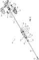
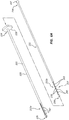
- FIG. 1 is a perspective view of a medical device 100 comprising an osteotome.
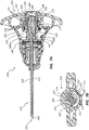
- FIG. 2 is an exploded view of the medical device 100.
- the medical device 100 is configured for accessing the interior of a vertebral body and/or for creating a pathway in vertebral cancellous bone.
- the pathway can receive bone fill material (e . g ., bone cement).
- the medical device 100 can include an extension member 105.
- the extension member 105 may be configured to be introduced through a pedicle of a vertebra.
- the extension member 105 can include a working end portion 110 at or adjacent a distal end 113 of the extension member 105.
- the working end portion 110 of the extension member 105 may be configured to be progressively actuated ( e . g ., by a practitioner) such that at least a portion of the working end portion 110 bends, curves, and/or is deflected a selected degree.
- An indicator or tip indicator 150 can communicate or indicate to a practitioner the direction of the deflection of the working end portion 110.
- the working end portion 110 of the extension member 105 can also be configured to be rotated. Deflection and/or rotating of the working end portion 110 can form a curved pathway and/or a cavity in a vertebral body. For example, the deflection and/or rotating can form a curved pathway and/or a cavity in the direction of the midline of the vertebral body.
- the medical device 100 can be withdrawn and bone fill material may be introduced into the pathway and/or cavity ( e . g ., via a bone cement injection cannula).
- the medical device 100 may be configured for use as a cement injector. For example, upon formation of the curved pathway and/or the cavity, bone cement may be injected through at least a portion of the medical device 100 ( e . g ., through a lumen of the medical device 100).
- the medical device 100 further includes a handle 115, wherein the handle 115 is coupled to a proximal end of the extension member 105.
- the extension member 105 includes a first or outer member 120 and a second or inner member 122.
- the outer member 120 has a proximal end 124 and a distal end 126.
- An outer member plate 125 can be coupled, or configured to be coupled, to the proximal end 124 of the outer member 120.
- the inner member 122 also has a proximal end 134 and a distal end 136.
- a spherical portion 137 is coupled, or configured to be coupled, to the proximal end 134 of the inner member 122.
- the extension member 105 can be coupled to the handle 115 to allow or permit a practitioner to drive the extension member 105 into a hard tissue (e.g., a bone) while contemporaneously, or substantially contemporaneously, actuating the working end portion 110 into a deflected or nonlinear configuration ( see , e . g ., FIG. 5C ).
- a hard tissue e.g., a bone
- actuating the working end portion 110 into a deflected or nonlinear configuration see , e . g ., FIG. 5C .
- the handle 115 may be formed from a polymer, a metal, or any other material that is suitable for withstanding impact forces that may be used to drive the medical device 100 into bone ( e.g ., via use of a hammer or similar device on the handle 115).
- the inner and outer members 120, 122 may be formed from a polymer, a metal, a metal alloy, or any other suitable material.
- the inner and outer members 122, 120 may be formed from a suitable metal alloy, such as stainless steel or a nickel titanium alloy (e.g., NITINOL).
- the outer diameter of the outer member 120 may be from about 1.5 mm to about 5.0 mm, about 2.0 mm to about 4.0 mm, about 2.5 mm to about 3.5 mm, or another suitable outer diameter.
- the inner diameter of the outer member 120 may be from about 1.0 mm to about 4.5 mm, about 1.5 mm to about 3.5 mm, about 2.0 mm to about 3.0 mm, or another suitable inner diameter.
- the handle 115 can include a grip portion 140 and an actuator portion 142, wherein the actuator portion 142 can be rotatable relative to the grip portion 140.
- the grip portion 140 may be configured to be grasped, gripped, and/or held by a user, and the actuator portion 142 may be configured to be actuated and/or rotated (with respect to the grip portion 140) by a user.
- the grip portion 140 can be coupled to the outer member 120.
- the grip portion 140 can be coupled to the outer member 120 via the outer member plate 125 and/or the distal collar 130.
- the actuator portion 142 can be operably coupled to the inner member 122.
- the actuator portion 142 can be coupled to the inner member 122 via the spherical portion 137, a female member 144, and/or a male member 147.
- the operation of each of the grip portion 140, the outer member 120, the outer member plate 125, and the distal collar 130 is discussed in further detail below.
- the operation of each of the actuator portion 142, the inner member 122, the spherical portion 137, the female member 144, and the male member 147 is also discussed in further detail below.
- the medical device 100 can further include one or more O-rings 118, 119.
- the proximal O-ring 118 may be configured to be disposed around at least a portion of the female member 144 ( e . g ., a distal portion of the female member 144).
- the proximal O-ring 118 may compensate for tolerance or fit between the female member 144 and other components to create a smooth interaction between such components.
- the distal O-ring 119 may be configured to be disposed within a portion of the distal collar 130.
- the distal O-ring 119 can be disposed within a locking member receiving portion 131 of the distal collar 130 (discussed in further detail below).
- the distal O-ring 119 may be configured to form a seal between the outer member plate 125 (e.g., a distal surface of the outer member plate 125) and the distal collar 130.
- the distal O-ring 119 may also compensate for differences in fit or tolerances between the components and facilitate smooth interaction of the components.
- the medical device 100 can further include a plurality of washers 185, 186, 187.
- the plurality of washers 185, 186, 187 may be configured to be disposed around the inner member 122 at a position proximal of the distal collar 130. Upon assembly of the medical device 100, the plurality of washers 185, 186, 187 can be disposed within at least a portion of the grip portion 140.
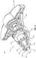
- FIG. 3 depicts a portion of the handle 115 of the medical device 100, wherein a portion ( e.g ., a half) of the grip portion 140 has been removed. Accordingly, at least a subset of the components of the medical device 100 that are disposed, or at least partially disposed, within the handle 115 are visible in this view.
- the grip portion 140 may include a first portion or half and a second portion or half, wherein the first and second portions are configured to be coupled to each other to form the grip portion 140.
- first portion of the grip portion 140 and the second portion of the grip portion 140 may be held together by one or more of an adhesive, a fastener, a snap fit, and/or annular bands 116, 117.
- the grip portion 140 may be a single component or the grip portion 140 may include three, four, or more portions.
- the distal collar 130 and the grip portion 140 can act as a torque limiter and/or release system. For example, if too much torque is applied to the outer member 120, the distal collar 130 and the grip portion 140 can be configured to allow the distal collar 130 to rotate with respect to the grip portion 140. In various embodiments, a portion of an inner surface 141 of the grip portion 140 can engage a portion of an outer surface of the distal collar 130, which is coupled to the proximal end 124 of the outer member 120 ( e.g., via the outer member plate 125).
- the distal collar 130 can comprise a body 133 and a plurality of resilient members 132 that extend distally from a distal end of the body 133 of the distal collar 130.
- each of the resilient members 132 can be substantially V-shaped.
- the outer surfaces of the resilient members 132 can engage a portion of the inner surface 141 of the grip portion 140, also referred to herein as the engagement surface 141.
- a contour or shape of the engagement surface 141 can substantially mirror the V-shape of the outer surfaces of the resilient members 132.
- Rotation of the actuator portion 142 displaces the inner member 122 ( i.e., proximally or distally), and the degree of deflection of the working end portion 110 can be adjusted.
- the rotation of the distal collar 130 can exceed a predetermined limit.
- too much torque i.e., at a level at or above the predetermined limit
- the resilient members 132 can be displaced radially inward allowing the distal collar 130 to rotate or turn.
- Such rotation of the distal collar 130 may release from about 0.03 Nm (0.25 inch-pounds) to about 1.13 Nm (10 inch-pounds) of torque, from about 0.06 Nm (0.5 inch-pounds) to about 0.85 Nm (7.5 inch-pounds) of torque, from about 0.06 Nm (0.5 inch-pounds) to about 0.56 Nm (5 inch-pounds) of torque, or from about 0.06 Nm (0.5 inch-pounds) to about 0.28 Nm (2.5 inch-pounds) of torque, or another suitable amount of torque.
- the medical device 100 can include the indicator 150.
- the indicator 150 can be positioned or disposed to communicate or indicate (e.g., to a practitioner) the orientation (such as indicating the direction of deflection) of the working end portion 110.
- the indicator 150 includes a lumen 151. Accordingly, the indicator 150 can be disposed over and/or around at least a portion of the outer member 120.
- the indicator 150 can also include an indicator arm 152, wherein the indicator arm 152 extends radially outward from a longitudinal axis of the indicator 150.
- the indicator arm 152 can be disposed in the direction of deflection of the working end portion 110.
- the working end portion 110 may be configured to deflect within a single plane and/or in a certain direction. Coupling the indicator 150 to the outer member 120 such that the outer member 120 and indicator 150 rotate together, may thus keep the indicator arm 152 aligned with the direction of deflection of the working end portion 110, even in instances wherein the outer member 120 and other components of the extension member 105 rotate with respect to the grip portion 140 due to slip or displacement of the torque limiting components described above.
- an end portion of the indicator arm 152 can form a bend or curve.
- the end portion of the indicator arm 152 can bend or curve proximally toward the actuator portion 142.
- the indicator arm 152 is disposed around at least a portion of an outside surface of the grip portion 140.
- an inside surface of the indicator arm 152 i.e., the surface of the indicator arm 152 that is disposed closest to a longitudinal axis of the outer member 120
- the indicator 150 may be formed from a polymer, a metal, or another suitable material.
- the indicator 150 may be formed from molded acrylonitrile butadiene styrene (ABS), polycarbonate, nylon, etc.
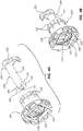
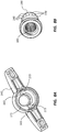
- FIG. 4A is a perspective view of the distal collar 130 and the indicator 150 in an uncoupled or unlocked configuration.
- FIG. 4B is a perspective view of the distal collar 130 and the indicator 150 in a coupled or locked configuration.
- the indicator 150 can include the lumen 151, wherein the lumen 151 can extend between a proximal end 153 and a distal end 154 of the indicator 150.
- the indicator arm 152 can extend from a position at or adjacent the distal end 154 of the indicator 150.
- the indicator 150 can also include a locking member 155, wherein the locking member 155 is disposed at or adjacent the proximal end 153 of the indicator 150.
- the locking member 155 can be configured to interlock and/or mate with a locking member receiving portion 131 of the distal collar 130.
- the locking member 155 can include one or more extensions 156 that extend radially outward from the longitudinal axis of the indicator 150.
- the locking member 155 may be configured to couple and/or secure the indicator 150 to the distal collar 130, for example, at the locking member receiving portion 131.
- the locking member receiving portion 131 can be substantially X-shaped or plus-sign-shaped.
- a first segment of the locking member receiving portion 131 can include an opening extending through the distal collar 130.
- a second segment of the locking member receiving portion 131 (that is rotationally offset by about 90° from the first segment of the locking member receiving portion 131) can include two indented portions 138 that are configured to receive and/or engage the two extensions 156 of the locking member 155.
- the locking member 155 and/or the locking member receiving portion 131 may be T-shaped, star-shaped, or otherwise suitably shaped.
- the locking member 155 may include one, three, four, or more extensions 156.
- the locking member receiving portion 131 may include one, three, four, or more indented portions.
- coupling the indicator 150 to the distal collar 130 may include proximally disposing the indicator 150 through the opening in the locking member receiving portion 131 such that the locking member 155 is disposed proximally of the locking member receiving portion 131.
- the indicator 150 can then be rotated around its longitudinal axis ( e.g ., about 90° as indicated in FIGS. 4A and 4B ) such that the extensions 156 are substantially aligned with the indented portions 138 of the locking member receiving portion 131.
- the indicator 150 can then be displaced distally in relation to the distal collar 130 such that the extensions 156 are disposed within each of the indented portions 138 of the locking member receiving portion 131.
- the distal collar 130 couples, or is configured to couple, both the outer member 120 and the indicator 150.
- the outer member plate 125 may mate with a recess on the distal collar 130 when the outer member 120 extends through the lumen 151 of the indicator 150.
- the indicator 150 can be coupled to the distal collar 130 such that the indicator arm 152 of the indicator 150 is substantially aligned with the direction of the deflection of the working end portion 110.
- the indicator arm 152 of the indicator 150 can remain substantially aligned with the direction of the deflection of the working end portion 110. Rotation of the distal collar 130 can result in or effect rotation of each of the indicator 150 and the outer member 120.
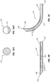
- FIG. 5A is a perspective view of the outer member 120 and the inner member 122.
- FIG. 5B is a cross-sectional view of the working end portion 110 of the medical device 100 of FIG. 1 in an undeflected configuration (e.g., a linear configuration).
- FIG. 5C depicts the working end portion 110 of FIG. 5B in a deflected configuration ( e . g ., a nonlinear configuration).
- the inner member 122 may be disposed within the lumen 121 of the outer member 120.
- the outer member plate 125 can be coupled to the proximal end 124 of the outer member 120.
- the spherical portion 137 can be coupled to the proximal end 134 of the inner member 122.
- the outer member 120 can include an outer working end portion 111a
- the inner member 122 can include an inner working end portion 111b.
- the outer working end portion 111a and the inner working end portion 111b can cooperate to form the working end portion 110.
- the outer working end portion 111a can include a plurality of slots or notches 162 (for clarity, only a subset of the slots 162 are labelled in the figures).
- the inner working end portion 111b of the inner member 122 can include a recessed portion 164.
- the working end portion 110 of the extension member 105 may be bent, curved, and/or deflected by cooperation between the plurality of slots 162 of the outer working end portion 111a and the recessed portion 164 of the inner working end portion 111b ( see , e . g ., FIG. 5C ).
- the working end portion 110 (including each of the outer and inner working end portions 111a, 111b) may be capable of bending, curving, and/or being deflected in a substantially tight radius.
- a distal end 113 of the working end portion 110 can be displaced at least about 5°, at least about 10°, at least about 20°, at least about 30°, at least about 40°, at least about 50°, at least about 60°, at least about 70°, at least about 80°, at least about 90°, at least about 100°, or more degrees relative to a longitudinal axis of a portion of the extension member 105 proximal of the working end portion 110.
- the distal end 113 of the working end portion 110 in the deflected configuration, can be displaced relative to the longitudinal axis of a portion of the extension member 105 proximal of the working end portion 110 from about 50° to about 110°, from about 60° to about 100°, or from about 70° to about 90° relative to the longitudinal axis of a portion of the extension member 105 proximal of the working end portion 110.
- the distal end 113 of the working end portion 110 in the undeflected configuration can be disposed substantially along the longitudinal axis of the extension member 105.
- the distal end 113 of the working end portion 110 can be displaced away from the longitudinal axis of the extension member 105 ( i.e., by a predetermined number of degrees away from the longitudinal axis).
- the slots 162 may be any slots that are perpendicular or angled relative to the longitudinal axis of the outer member 120. As shown in FIG. 5B , the recessed portion 164 of the inner member 122 may be disposed on an opposite side, or a substantially opposite side, of the working end portion 110 relative to the plurality of slots 162 of the outer member 120. In other words, the recessed portion 164 of the inner member 122 can be substantially oriented in opposition to the plurality of slots 162 of the outer member 120 ( i.e., when the inner member 122 is coupled to the outer member 120 as illustrated).
- the configuration of the inner member 122 including the recessed portion 164, as described herein and/or as illustrated, may inhibit or prevent breaking, crimping, folding, or other failure of the inner working end portion 111b during bending, curving, and/or deflection of the working end portion 110.
- a force of about 32 pounds may be exerted by the working end portion 110.
- the inner member 122 and/or the recessed portion 164 may be configured to exert a force of greater than about 89 N (about 20 pounds), greater than about 116 N (about 26 pounds), greater than about 169 N (about 38 pounds), greater than about 196 N (about 44 pounds), or a force of another suitable magnitude.
- the distal end 126 of the outer member 120 can be coupled to the distal end 136 of the inner member 122, for example, at a coupling portion 160.
- a coupling portion (analogous to the coupling portion 160) may be disposed more proximally relative to the distal end 113 or the working end portion 110 than the illustrated coupling portion 160.
- the outer member 120 may be welded to the inner member 122 at the coupling portion 160 ( e . g ., the outer member 120 may be laser-welded to the inner member 122).
- Other mechanisms of coupling the outer member 120 to the inner member 122 are also within the scope of this disclosure, e . g ., glue, interlocking components, etc.
- the outer member 120 may be bent, curved, or deflected as depicted in FIG. 5C .
- rotation of the actuator portion 142 a selected amount can bend, curve, and/or deflect the working end portion 110 to a selected degree.
- the recessed portion 164 may allow or permit the inner working end portion 111b of the inner member 122 to bend, curve, and/or be deflected.
- the direction of bending, curving, and/or deflection of the inner working end portion 111b may limited or restricted, however, by the location or position of the slots 162 of the outer member 120.
- the curvature of the working end portion 110 may be controlled or limited by the spacing, shape, and/or angle of the slots 162.
- the working end portion 110 may transition from a linear configuration (such as shown in FIG. 5B ) to a curved configuration in which the slots 162 of the outer portion 120 are disposed on the concave side of the bend (such as shown in FIG. 5C ).
- Distal displacement of the inner member 122 with respect to a proximal portion of the outer member 120 causes the working end portion 110 to curve in the opposite direction, such that the slots 162 will be disposed on the convex side of the curve.
- the recessed portion 164 may flex within the outer member 120 as shown, for example, in FIGS. 5B and 5C .
- the distal coupling of the outer member 120 and inner member 122, together with the relative positions of the slots 162 and the recessed portion may thus restrict the bending of the working portion to bending within a single plane.
- each of the distal end 126 of the outer member 120 and the distal end 136 of the inner member 122 is beveled.
- the beveled configuration can be used or aid in entry of at least a portion of the medical device 100 ( e.g., the working end portion 110) through the cortical bone of a vertebral body.
- only one of the distal end 126 of the outer member 120 or the distal end 136 of the inner member 122 may beveled.
- the inner member 122 and/or the inner working end portion 111b may be machined to form the recessed portion 164.
- Other suitable methods e . g ., molding
- the outer member 120 may be laser-cut to form the plurality of slots 162.
- Other suitable methods may also be used to form the plurality of slots 162.
- FIG. 5A1 is a cross-sectional view of the inner member 122 through line 5A1-5A1 of FIG. 5A .
- FIG. 5A2 is a cross-sectional view of the inner member 122 through line 5A2-5A2 of FIG. 5A .
- a cross-section transverse to a longitudinal axis of the inner member 122 at a position proximal of the recessed portion 164 can be substantially circular.
- a cross-section of the inner member 122 at this position may be otherwise shaped; for example, the cross-section may be square, rectangular, oval, etc.
- a cross-section transverse to the longitudinal axis of the inner member 122 at the recessed portion 164 can be substantially segmental ( i.e., a segment of the circle depicted in FIG. 5A1 ).
- a cross-section of the inner member 122 at the recessed portion 164 may be otherwise shaped; for example, the cross-section may be a portion or segment of a square, a rectangle, an oval, etc.
- the osteotome or medical device 100 can include a handle 115 and an extension member 105 operably coupled to the handle 115.
- the extension member 105 can include an inner member 122 disposed within at least a portion of an outer member 120.
- actuation or rotation of at least a portion of the handle 115 may be configured to bend, curve, and/or deflect a working end portion 110 of the extension member 105.
- the working end portion 110 can be disposed adjacent a distal end 113 of the extension member 105 ( see , e . g ., FIG. 1 ).
- the medical device 100 can further include an indicator 150 operably coupled to the outer member 120.
- the indicator 150 can communicate a direction of deflection of the working end portion 110 to a user.
- the indicator 150 can include an elongate body 157 and a locking member 155 coupled to a proximal end of the elongate body 157.
- the locking member 155 may be configured to operably couple the indicator 150 to the outer member 120.
- the indicator 150 can further include an indicator arm 152 coupled to a distal end of the elongate body 157.
- the indicator arm 152 can extend radially outward from a longitudinal axis of the elongate body 157.
- the indicator arm 152 may be configured to communicate the direction of deflection of the working end portion 110 to the user.
- the handle 115 can include an actuator portion 142 operably coupled to the working end portion 110.
- the handle 115 can further include a grip portion 140 disposed distal of and operably coupled to the actuator portion 142.
- actuation and/or rotation of the actuator portion 142 may be configured to longitudinally displace the inner member 122 relative to the outer member 120 such that the working end portion 110 can transition between a deflected configuration and an undeflected configuration, or vice versa.
- the locking member 155 of the indicator 150 can be disposed within at least a portion of the grip portion 140. Furthermore, the indicator arm 152 can be disposed outside or external of the grip portion 140 such that the indicator arm 152 is visible to the user. The indicator arm 152 can extend around at least a portion of an outer surface of the grip portion 140. In various embodiments, the indicator 150 and/or the indicator arm 152 may be a first color (e . g ., white) and the grip portion 140 may be a second color (e.g., blue) such that a visibility ( i.e., to a user) of the indicator 150 and/or the indicator arm 152 may be enhanced.
- a first color e . g ., white
- the grip portion 140 may be a second color (e.g., blue) such that a visibility ( i.e., to a user) of the indicator 150 and/or the indicator arm 152 may be enhanced.
- the medical device 100 may further include a distal collar 130 disposed within and coupled to the handle 115.
- the distal collar 130 may include an outer member receiving portion or outer member plate receiving portion 135 configured to couple an outer member plate 125 and/or a proximal end 124 of the outer member 120 to the distal collar 130.
- the distal collar 130 may further include the locking member receiving portion 131 configured to couple a proximal end 153 and/or a locking member 155 of the indicator 150 to the distal collar 130.
- the outer member 120 and the indicator 150 may not be rotatable relative to the distal collar 130 ( e.g., due at least in part to the coupling of each of the outer member 120 and the indicator 150 to the distal collar 130).
- the locking member 155 can be coupled to the proximal end 153 of the indicator 150.
- the locking member 155 can include at least one extension 156 extending radially outward from a longitudinal axis of the indicator 150.
- the locking member 155 can include two extensions 156, wherein each of the two extensions 156 is disposed on an opposite side of the elongate body 157 of the indicator 150 ( see , e . g ., FIGS. 4A and 4B ).
- the at least one extension 156 may engage, or be configured to engage, the locking member receiving portion 131 such that the indicator 150 is not substantially rotatable relative to the distal collar 130.
- the medical device 100 may include a handle 115 and an extension member 105 coupled to, and extending distally from, the handle 115.
- the extension member 105 may include the outer member 120.
- the outer member 120 may include a lumen 121 extending from at least a distal end 126 of the outer member 120.
- the lumen 121 may extend from a distal end 126 to a proximal end 124 of the outer member 120.
- the plurality of slots or notches 162 can be disposed in a wall of the outer member 120.
- the plurality of slots 162 may be disposed along at least a portion of a length of the distal end portion of the outer member 120.
- the extension member 105 includes the inner member 122.
- the inner member 122 is disposed within at least a portion of the outer member 120.
- the inner member 122 can include a recessed portion 164.
- the recessed portion 164 can be disposed along at least a portion of a length of a distal end portion of the inner member 122.
- the distal end portions of the outer and inner members 120, 122 (including the plurality of slots 162 and the recessed portion 164, respectively) cooperate and/or interact to form the working end portion 110 of the extension member 105.
- the plurality of slots 162 can be radially offset from the recessed portion 164.
- the plurality of slots 162 may be disposed on an opposite side (or substantially opposite side) of the working end portion 110 from the recessed portion 164. Stated another way, the plurality of slots 162 may be circumferentially offset from the recessed portion 164, meaning offset along a circumference of the working end portion 110. Additionally, the plurality of slots 162 and the recessed portion 164 can cooperate and/or interact to allow or permit deflection of the working end portion 110 (e.g., upon actuation or rotation of the handle 115). An arrangement of the plurality of slots 162 disposed on the opposite side from the recessed portion may be configured to limit deflection of the working end portion to a single plane.
- a length of the recessed portion 164 may be substantially equal to a length of the portion of the inner member 122 including the plurality of slots 162. Stated another way, the distance between the distal-most slot 162 and the proximal-most slot 162 may be substantially equal to the distance between the distal end 168 of the recessed portion 164 and the proximal end 166 of the recessed portion 164. In some other embodiments, the length of the recessed portion 164 may be greater than the length of the portion of the inner member 122 including the plurality of slots 162. In yet some other embodiments, the length of the recessed portion 164 may be less than the length of the portion of the inner member 122 including the plurality of slots 162.
- the plurality of slots 162 and/or the recessed portion 164 can substantially limit deflection of the working end portion 110 to a single plane.
- the working end portion 110 may be configured to bend, curve, and/or be deflected in only a single plane ( i.e., due at least in part to the plurality of slots 162 and/or the recessed portion 164).
- the distal end 126 or distal end portion of the outer member 120 can be coupled ( e . g ., fixedly coupled) to the distal end 136 or distal end portion of the inner member 122 ( e.g., via a weld). Actuation of the handle 115 can longitudinally displace the inner member 122 relative to the outer member 120. Such longitudinal displacement can transition the working end portion 110 from an undeflected configuration to a deflected configuration.
- the fixed coupling of the outer member 120 to the inner member 122 can inhibit or limit rotational movement of the outer member 120 relative to the inner member 122.
- the inner member 122 can include a wire or be formed from a wire.
- a thickness of the wire distal of the recessed portion 164 may be greater than a thickness of the wire at the recessed portion 164.
- a thickness of the wire proximal of the recessed portion 164 may be greater than the thickness of the wire at the recessed portion 164.
- the recessed portion 164 can include a distal end 168, a medial portion 169, and a proximal end 166. With reference to FIG. 5A , the medial portion 169 can have a first thickness.
- the portion of the inner member 122 disposed proximal of the recessed portion 164 can have a second thickness, and a portion of the inner member 122 disposed distal of the recessed portion 164 can have a third thickness.
- each of the second and third thicknesses is greater than the first thickness.
- the thickness of the recessed portion 164 (or at least a portion of the recessed portion 164) is less than a thickness of the remaining portions of the inner member 122 (or at least portions of the remaining portions of the inner member 122).
- the thickness of the inner member 122 can transition from the first thickness to the second thickness at the proximal end 166 of the recessed portion 164, and the thickness of the inner member 122 can transition from the first thickness to the third thickness at the distal end 168 of the recessed portion 164.
- the medial portion 169 and/or the recessed portion 164 may be configured to be bent, curved, or deflected, while the portions of the inner member 122 proximal and/or distal of the recessed portion 164 may not be configured to be bent, curved, or deflected.
- the medial portion 169 and/or the recessed portion 164 can be resilient, as described above.
- FIGS. 6A-6C illustrate an outer member 220 and an inner member 222 that can, in certain respects, resemble the outer member 120 and the inner member 122 described in connection with FIGS. 1 , 2 , and 5A-5C .
- FIGS. 6A-6C illustrate an outer member 220 and an inner member 222 that can, in certain respects, resemble the outer member 120 and the inner member 122 described in connection with FIGS. 1 , 2 , and 5A-5C .
- FIGS. 6A-6C illustrate an outer member 220 and an inner member 222 that can, in certain respects, resemble the outer member 120 and the inner member 122 described in connection with FIGS. 1 , 2 , and 5A-5C .
- FIGS. 6A-6C illustrate an outer member 220 and an inner member 222 that can, in certain respects, resemble the outer member 120 and the inner member 122 described in connection with FIGS. 1 , 2 , and 5A-5C .
- FIGS. 6A-6C illustrate analogous
- FIG. 6A is a perspective view of the outer member 220 and the inner member 222.
- FIG. 6B is a cross-sectional view of a working end portion 210 of an extension member of a medical device or osteotome (analogous to the extension member 105 and the medical device 100) in an undeflected configuration.
- FIG. 6C depicts the working end portion 210 of FIG. 6B in a deflected configuration.
- the inner member 222 may be disposed within a lumen 221 of the outer member 220.
- An outer member plate 225 can be coupled to a proximal end 224 of the outer member 220, and a spherical portion 237 can be coupled to a proximal end 234 of the inner member 222.
- the outer member 220 can include an outer working end portion 211a
- the inner member 222 can include an inner working end portion 211b.
- the outer working end portion 211a and the inner working end portion 211b can cooperate to form the working end portion 210.
- the outer working end portion 211a can include a plurality of slots or notches 262.
- the inner working end portion 211b can include a reinforced recessed portion 264.
- the reinforced recessed portion 264 can include a plurality of reinforcement or support members 265. As illustrated, the recessed portion 264 includes four reinforcement members 265. In some embodiments, the recessed portion 264 may include one, two, three, five, six, or more reinforcement members 265.
- the one or more reinforcement members 265 can strengthen and/or support the recessed portion 264. For example, when a force is exerted on the recessed portion 264 ( e . g ., during bending, curving, and/or deflection of the working end portion 210), the one or more reinforcement members 265 tend to maintain the radial position of the recessed portion within the outer member 220.
- the one or more reinforcement members 265 can extend across the space between a surface of the recessed portion 264 and an inside surface of the outer member 220 when the inner member 222 is disposed within the outer member 220 as illustrated in FIG. 6B . Accordingly, the one or more reinforcement members 265 can support the recessed portion 264. Analogously, the one or more reinforcement members 265 can support a portion of the outer member 220 that is disposed adjacent the recessed portion 264.
- the reinforced recessed portion 264 of the inner member 222 may be disposed on an opposite side of the working end portion 210 relative to the plurality of slots 262 of the outer member 220.
- the configuration of the inner member 222, the recessed portion 264, and the reinforcement member 265, as described herein and/or as illustrated, may inhibit or limit breaking, crimping, folding, or other failure of the inner working end portion 211b during bending, curving, and/or deflection of the working end portion 210.
- the distal end 226 of the outer member 220 can be coupled to the distal end 236 of the inner member 222 at a coupling portion 260. Accordingly, when the inner member 222 is displaced or translated in a proximal direction ( i.e., by rotation of an actuator portion analogous to the actuator portion 142), the outer member 220 may be bent, curved, or deflected as depicted in FIG. 6C . Furthermore, rotation of the actuator portion a selected amount can bend, curve, and/or deflect the working end portion 210 to a selected degree.
- the recessed portion 264 may allow or permit the inner working end portion 211b of the inner member 222 to bend, curve, and/or be deflected in multiple directions.
- the direction of bending, curving, and/or deflection of the inner working end portion 211b may be limited or restricted, however, by the location or position of the slots 262 of the outer member 220.
- the curvature of the working end portion 210 may be controlled or limited by the spacing, shape, and/or angle of the slots 262.
- each of the distal end 226 of the outer member 220 and the distal end 236 of the inner member 222 is beveled. In certain embodiments, only one of the distal end 226 of the outer member 220 or the distal end 236 of the inner member 222 may be beveled.
- the one or more reinforcement members 265 can be disposed within at least a portion of the recessed portion 264.
- the reinforcement member 265 can extend from a surface 270 of the recessed portion 264 to a position at or adjacent an inner surface of the outer member 220.
- the one or more reinforcement members 265 can be integrally formed with the inner member 222. In some other embodiments, the one or more reinforcement members 265 and the inner member 222 may be discrete components.
- FIG. 7A is a cross-sectional view of a portion of the medical device 100 of FIG. 1 .
- FIG. 7B is a cross-sectional view of the medical device 100 through line 7B-7B of FIG. 1 .
- the medical device 100 can include the handle 115.
- the handle 115 can include the actuator portion 142 and the grip portion 140.
- rotation of the actuator portion 142 relative to the grip portion 140 can bend, curve, and/or deflect the working end portion 110 of the extension member 105.
- the actuator portion 142 can be coupled to the female member 144, wherein the female member 144 can be at least partially disposed within an inner cavity 171 of the actuator portion 142.
- the actuator portion 142 may be coupled to the female member 144 by means of a snap-fit joint 149 at a proximal end of each of the actuator portion 142 and the female member 144.
- the actuator portion 142 can include one or more resilient arms 143 disposed within the inner cavity 171 of the actuator portion 142.
- the actuator portion 142 includes two resilient arms 143, wherein the resilient arms 143 are disposed in opposition, or substantial opposition, to each other within the inner cavity 171.
- the actuator portion 142 may include three, four, or more resilient arms 143.
- the disposition of the resilient arms 143 within the actuator portion 142 can vary.
- the resilient arms 143 may be substantially evenly spaced around a circumference of the inner cavity 171.
- the resilient arms 143 may be unevenly spaced or otherwise disposed within the actuator portion 142.
- one or more teeth 173 may extend radially inward from the one or more resilient arms 143.
- each of the one or more resilient arms 143 includes two teeth 173 (e.g., rounded teeth 173).
- the one or more resilient arms 143 may include one, three, four, or more teeth 173.
- a first resilient arm may include a different number of teeth than a second resilient arm ( e . g ., the first resilient arm may include one tooth, and the second resilient arm may include three teeth).
- the shape of the one or more teeth 173 may vary.
- the teeth 173 may be semicircular, triangular, or otherwise suitably shaped.
- the female member 144 can include a plurality of ridges 145 and grooves 146. Stated another way, an outside surface of the female member 144 may be gear-like.
- the ridges 145 may extend radially outward from the outside surface of the female member 144 and/or in relation to the grooves 146.
- the ridges 145 and grooves 146 may be configured to engage or interact with the teeth 173 of the actuator portion 142.
- the engagement of at least a portion of the ridges 145 and/or the grooves 146 with at least a portion of the teeth 173 can further couple the actuator portion 142 to the female member 144. This engagement can allow for or drive rotation of the female member 144 upon rotation of the actuator portion 142.
- the male member 147 can be coupled to the inner member 122. As illustrated, the proximal end 134 of the inner member 122 is coupled to the male member 147.
- the spherical portion 137 which is coupled to the proximal end 134 of the inner member 122, can be disposed within a portion of the male member 147 such that the male member 147 is coupled to the inner member 122.
- Such coupling can allow the male member 147 to displace ( e . g ., longitudinally) the inner member 122 without substantially rotating or applying torque on the inner member 122.
- the spherical portion 137 may be configured to rotate within at least a portion of the male member 147 (e.g., within a substantially spherical cavity).
- the male member 147 can include a proximal threaded portion 177 and a distal portion 179.
- the distal portion 179 can include a first surface 180a and a second surface 180b.
- the distal portion 179 can be at least partially disposed in a proximal channel 167 of the grip portion 140, wherein each of the first and second surfaces 180a, 180b can be substantially planar or flat.
- an engagement or interaction between the first and second surfaces 180a, 180b of the male member 147 and at least a portion of an inner surface of the proximal channel 167 can prevent or restrict the male member 147 from rotating relative to the grip portion 140.
- a plurality of threads 178 can be disposed on at least a portion of the proximal threaded portion 177 of the male member 147.
- the female member 144 can further include an inner cavity 182, and a plurality of threads 183 can be disposed on at least a portion of a surface of the inner cavity 182.
- the plurality of threads 178 of the male member 147 can be configured to engage or interact (e.g., threadably engage or interact) with the plurality of the threads 183 of the female member 144.
- the male member 147 may be displaced or linearly displaced (e.g., proximally or distally) relative to the female member 144 due at least in part to threaded engagement between each of the male member 147 and the female member 144.
- Such a configuration can allow a user to impart a substantially large force on at least a subset of the components disposed within the handle 115 ( e.g., due to translation of force from the actuator portion 142 to the female member 144 and other components that may be operably coupled to the female member 144).
- the male member 147 can be displaced proximally in relation to the grip portion 140. Proximal displacement of the male member 147 can result in or effect proximal displacement of the inner member 122 in relation to the outer member 120. Further, proximal displacement of the inner member 122 in relation to the outer member 120 can result in bending, curving, and/or deflection of the working end portion 110 as the inner member 122 is coupled to the outer member 120 at the coupling portion 160.
- a proximal end of the proximal threaded portion 177 of the male member 147 may abut, or be configured to abut, a portion of the surface of the inner cavity 182 of the female member 144 ( e . g ., the male member 147 may hit a hard stop).
- the male member 147 may still be displaceable within the female member 144. For example, there may still be a gap between the proximal end of the proximal threaded portion 177 of the male member 147 and the surface of the inner cavity 182 of the female member 144. Accordingly, the male member 147 may have a potential distance to travel or be displaced. If the user continues to rotate the actuator portion 142 in this configuration ( i .
- the holding power of the resilient arms 143 may be exceeded (due to resistance to bending of the working portion 110 due to its position within the bone), one or more of the resilient arms 143 may be pushed radially outward, and the one or more teeth 173 may be displaced or slip over one or more of the ridges 145.
- a tooth 173 may be displaced from a first groove 146 to an adjacent groove 146 ( e . g ., a second groove 146).
- the tooth 173 may be displaced from a first groove 146 to a third groove 146, a fourth groove 146, etc.
- the resilient arms 143 and the ridges 145 and/or the grooves 146 can interact analogously whether the actuator portion 142 is being rotated clockwise or counter-clockwise ( e . g ., by a user).
- a cross-section of the resilient arms 143 may be thicker or thinner than the illustrated resilient arms 143.
- the resilient arms 143 may be shorter or longer than the illustrated resilient arms 143.
- Such adjustments or modifications to the configuration of the resilient arms 143 can be used to select a desired force (e.g., a release force) at which the resilient arms 143 extend radially outward and release torque on at least a subset of the components of the handle 115.
- the release force may be greater than a force required to deflect the working end portion 110. In certain embodiments, the release force may be less than a force that may result in damage to at least a portion of the male member 147 and/or the female member 144.
- the coupling of the female member 144 and the actuator portion 142 as described above may be configured to prevent a user from exerting an excessive amount of torque on the extension member 105, which could potentially damage one or more components ( e . g ., the inner member 122 or the male member 147) of the medical device 100.
- the plurality of teeth 173 that project radially inward from the resilient arms 143 may be configured to deflect outward when too much torque is provided, thereby causing the actuator portion 142 to disengage from the ridges 145 and/or the grooves 146 on the female member 144.
- the actuator portion 142 may disengage from the ridges 145 and/or the grooves 146 on the female member 144. Such disengagement can prevent the user from exerting an excessive amount of force on the medical device 100.
- the actuator portion 142 may function as a torque limiter and/or release system.
- disengagement can prevent the spherical portion 137 from being displaced, breaking, and/or extruding through a distal end of the male member 147.
- Such disengagement can also prevent or restrict the threads 178 of the male member 147 and/or the threads 183 of the female member 144 from failing or being stripped. Accordingly, proper functioning of the medical device 100 can be maintained.
- the medical device 100 may be configured for treating a hard tissue.
- the medical device 100 can include the extension member 105, wherein the extension member 105 includes the inner member 122 disposed within at least a portion of the outer member 120.
- the handle 115 can be releasably coupled to the extension member 105.
- actuation (e . g ., rotation) of the handle 115 can be configured to transition the working end portion 110 of the extension member 105 between the deflected configuration and the undeflected configuration.
- a torque release mechanism is coupled to each of the handle 115 and the inner member 122. According to the invention, the torque release mechanism is configured to transition the medical device 100 between a torque release configuration and a torque retention configuration (as described in further detail below).
- the handle 115 can include the actuator portion 142, wherein the actuator portion 142 can be releasably coupled to the inner member 122.
- the handle 115 can also include a grip portion 140, wherein the grip portion 140 is disposed distally of and is rotatably coupled to the actuator portion 142.
- the grip portion 140 can be releasably coupled to the outer member 120.
- the medical device 100 may include more than one torque release mechanisms.
- a first or proximal torque release mechanism may be coupled to each of the actuator portion 142 and the inner member 122.
- the proximal torque release mechanism may be configured to transition the inner member 122 between a torque release configuration ( e .
- a second or distal torque release mechanism may be coupled to each of the grip portion 140 and the outer member 120.
- the distal torque release mechanism may be configured to transition the outer member 120 between a torque release configuration ( e . g ., a distal torque release configuration) and a torque retention configuration ( e . g ., a distal torque retention configuration).
- the torque release mechanism can further be configured to uncouple the inner member 122 from the handle 115 when an amount of torque applied to the handle 115 exceeds a predetermined value.
- the torque release mechanism may be configured to limit or prevent damage to the medical device 100 ( e.g., due to the application of excessive force to the handle 115 and/or the medical device 100).
- the proximal torque release mechanism may be configured to uncouple the inner member 122 from the actuator portion 142 when an amount of torque applied to the actuator portion 142 exceeds a first predetermined value.
- the distal torque release mechanism may be configured to uncouple the outer member 120 from the grip portion 140 when an amount of torque applied to the outer member 120 exceeds a second predetermined value.
- torque may be transferred between the handle 115 and the extension member 105 via the torque release mechanism, or the proximal torque release mechanism, when the medical device 100 and/or the torque release mechanism is in the torque retention configuration.
- torque may not be transferred between the handle 115 and the extension member 105 via the torque release mechanism, or the proximal torque release mechanism, when the medical device 100 and/or the torque release mechanism is in the torque release configuration.
- the handle 115 can include the actuator portion 142, wherein the actuator portion 142 can be releasably coupled to the working end portion 110 at least via the inner member 122.
- actuation of the actuator portion 142 may be configured to longitudinally displace the inner member 122 relative to the outer member 120. Such displacement can transition the working end portion 110 between the deflected configuration and the undeflected configuration.
- a first portion of the torque release mechanism, or the proximal torque release mechanism may be disposed within the actuator portion 142, and a second portion of the torque release mechanism, or the proximal torque release mechanism, may be coupled to the proximal end 134 of the inner member 122. Furthermore, the first and second portions of the torque release mechanism, or the proximal torque release mechanism, may be releasably coupled to each other.
- the first portion of the torque release mechanism, or the proximal torque release mechanism may include at least one tooth 173 extending radially inward from the inside surface of the actuator portion 142.
- the second portion of the torque release mechanism, or the proximal torque release mechanism may include at least one groove 146 extending radially inward from an outside surface of the female member 144.
- the at least one groove 146 i.e., of the second portion of the torque release mechanism or the proximal torque release mechanism
- the at least one tooth 173 can be coupled to the resilient arm 143, wherein the resilient arm 143 extends radially inward from at least a portion of the inside surface of the actuator portion 142.
- a distal portion of the resilient arm 143 may be displaced radially outward relative to a longitudinal axis of the actuator portion 142 when the medical device 100 and/or the torque release mechanism is in the torque release configuration. Such displacement of at least a portion of the resilient arm 143 can disengage the at least one tooth 173 from the at least one groove 146.
- the medical device 100 can further include the male member 147.
- the male member 147 can be coupled to the proximal end 134 of the inner member 122. Additionally, the male member 147 can be threadably engaged with the female member 144 such that actuation ( e . g ., rotation) of the female member 144 can longitudinally displace the male member 147 relative to the female member 144.
- Actuation of the actuator portion 142 can be configured to engage, or result in the engagement of, the at least one tooth 173 with the at least one groove 146. Such engagement may result in actuation of the female member 144 when the medical device 100 is in the torque retention configuration. Furthermore, actuation of the female member 144 may be configured to longitudinally displace the inner member 122 relative to the outer member 120. In certain embodiments, the at least one tooth 173 may be configured to be disengaged from the at least one groove 146 when the medical device 100 is in the torque release configuration. In such a configuration ( e .
- actuation of the actuation portion 142 may not actuate or result in actuation of the female member 144.
- actuation of the actuator portion 142 may include rotation of at least a portion of the actuator portion 142.
- actuation of the female member 144 may include rotation of at least a portion of the female member 144.
- the present disclosure is directed to methods of treating a hard tissue (e . g ., a bone) of a patient or subject.
- the methods can include obtaining the medical device (such as the medical device or osteotome 100).
- the medical device as described above, can include an outer member and an inner member disposed within a portion of the outer member. Furthermore, a distal end of the outer member can be coupled to ( e . g ., fixedly coupled to) a distal end of the inner member. The distal end portions of the outer and inner members can form a working end portion.
- the methods of treating the hard tissue can further include advancing the working end portion of the medical device into at least a portion of the hard tissue of the patient.
- the working end portion can be advanced in a first direction.
- the methods can further include actuating the medical device ( e . g ., via a handle) to longitudinally displace the inner member relative to the outer member. Accordingly, a plurality of slots disposed along the distal end portion of the outer member and a recessed portion disposed along the distal end portion of the inner member can interact to transition the working end portion from an undeflected configuration to a deflected configuration.
- the methods of treating the hard tissue of the patient can further include observing a disposition or direction of an indicator operably coupled to the outer member. Such observation can be used to determine a direction (e.g., the first direction) of the deflection of the working end portion.
- a direction e.g., the first direction
- the user may desire to adjust a direction of the deflection relative to the hard tissue being treated. Accordingly, the user can adjust the medical device to advance the working end portion in a second direction ( e . g ., based at least in part on the direction of the deflection communicated by the indicator).
- the methods of treating the hard tissue of the patient can include obtaining a medical device as described herein (e . g ., medical device 100).
- the medical device can include an outer member and an inner member disposed within at least a portion of the outer member. Distal end portions of each of the outer and inner members may cooperate to form a working end portion.
- a handle can be releasably coupled to the working end portion.
- the methods of treating the hard tissue of the patient can further include advancing the working end portion into the hard tissue of the patient.
- a practitioner or user may actuate at least a portion of the handle to transition the working end portion between an undeflected configuration and a deflected configuration.
- the practitioner may apply torque to the handle.
- the level of torque applied to the handle may exceed a predetermined value. Accordingly, further actuation of the handle may uncouple the handle from the working end portion ( e . g ., via a torque release mechanism).
- the practitioner may decrease an amount of torque applied to the handle such that the handle is recoupled to, or recouples, the working end portion.
- the practitioner may cease or stop applying torque to the handle such that the handle is recoupled to, or recouples, the working end portion.
- the practitioner may adjust a position of the working end portion ( e . g ., within the hard tissue). Accordingly, the amount of torque applied to the medical device may be decreased.
- the practitioner may then actuate the handle to further transition the working end portion between the undeflected configuration and the deflected configuration.
- FIGS. 1-8B additional methods and/or method steps can be derived from FIGS. 1-8B and the corresponding disclosure.
- Any methods disclosed herein comprise one or more steps or actions for performing the described method.
- the method steps and/or actions may be interchanged with one another. In other words, unless a specific order of steps or actions is required for proper operation of the embodiment, the order and/or use of specific steps and/or actions may be modified.
Claims (15)
- Dispositif médical (100) destiné à traiter un tissu dur, le dispositif médical (100) comprenant :un élément d'extension (105) comprenant un élément interne (122) disposé au sein d'un élément externe (120) ;une poignée (115) couplée de manière détachable à l'élément d'extension (105), dans lequel l'actionnement de la poignée (115) est configuré pour faire passer une partie d'extrémité de travail (110) de l'élément d'extension (105) entre une configuration déviée et une configuration non déviée, la partie d'extrémité de travail (110) disposée adjacente à une extrémité distale (113) de l'élément d'extension (105) ; etun mécanisme de libération de couple,dans lequel le mécanisme de libération de couple est configuré pour faire passer le dispositif médical entre une configuration de libération de couple et une configuration de rétention de couple,caractérisé en ce quele mécanisme de libération de couple est couplé à la poignée (115) et à l'élément interne (122).
- Dispositif médical (100) selon la revendication 1, dans lequel le mécanisme de libération de couple est configuré pour découpler l'élément interne (122) de la poignée (115) quand une grandeur de couple appliquée à la poignée (115) dépasse une valeur prédéterminée.
- Dispositif médical (100) selon la revendication 1 ou 2, dans lequel le couple est transféré entre la poignée (115) et l'élément d'extension (105) par le biais du mécanisme de libération de couple quand il est dans la configuration de rétention de couple, et dans lequel le couple n'est pas transféré entre la poignée (115) et l'élément d'extension (105) par le biais du mécanisme de libération de couple quand il est dans la configuration de libération de couple.
- Dispositif médical (100) selon l'une quelconque des revendications 1 à 3, dans lequel la poignée (115) comprend :une partie d'actionneur (142) couplée de manière détachable à la partie d'extrémité de travail (110) par le biais de l'élément interne (122),dans lequel l'actionnement de la partie d'actionneur (142) est configuré pour déplacer de manière longitudinale l'élément interne (122) par rapport à l'élément externe (120) de sorte que la partie d'extrémité de travail (110) passe entre la configuration déviée et la configuration non déviée,dans lequel une première partie du mécanisme de libération de couple est disposée au sein de la partie d'actionneur (142) et une deuxième partie du mécanisme de libération de couple est couplée à une extrémité proximale (134) de l'élément interne (122), etdans lequel les première et deuxième parties du mécanisme de libération de couple sont couplées de manière détachable l'une à l'autre.
- Dispositif médical (100) selon la revendication 4, dans lequel la première partie du mécanisme de libération de couple comprend au moins une dent (173) s'étendant de manière radiale vers l'intérieur à partir d'une surface intérieure de la partie d'actionneur (142), dans lequel la deuxième partie du mécanisme de libération de couple comprend au moins une rainure (146) s'étendant de manière radiale vers l'intérieur à partir d'une surface extérieure d'un élément femelle (144), et dans lequel l'au moins une rainure (146) est configurée pour entrer en prise avec l'au moins une dent (173).
- Dispositif médical (100) selon la revendication 5, dans lequel l'au moins une dent (173) est couplée à un bras élastique (143), le bras élastique (143) s'étendant de manière radiale vers l'intérieur à partir de la surface intérieure de la partie d'actionneur (142).
- Dispositif médical (100) selon la revendication 6, dans lequel une partie distale du bras élastique (143) est déplacée de manière radiale vers l'extérieur par rapport à un axe longitudinal de la partie d'actionneur quand il est dans la configuration de libération de couple de sorte qu'au moins une dent (173) est sortie de prise d'avec l'au moins une rainure (146).
- Dispositif médical (100) selon l'une quelconque des revendications 5 à 7, comprenant en outre un élément mâle (147) couplé à l'extrémité proximale de l'élément interne (122), dans lequel l'élément mâle (147) est entré en prise par filetage avec l'élément femelle (144) de sorte que l'actionnement de l'élément femelle (144) est configuré pour déplacer de manière longitudinale l'élément mâle (147) par rapport à l'élément femelle (144).
- Dispositif médical (100) selon l'une quelconque des revendications 5 à 8, dans lequel l'actionnement de la partie d'actionneur (142) est configuré pour mettre l'au moins une dent (173) en prise avec l'au moins une rainure (146) pour actionner l'élément femelle (144) quand il est dans la configuration de rétention de couple, et dans lequel l'actionnement de l'élément femelle (144) est configuré pour déplacer de manière longitudinale l'élément interne (122) par rapport à l'élément externe (120).
- Dispositif médical (100) selon l'une quelconque des revendications 5 à 9, dans lequel l'au moins une dent (173) est configurée pour être sortie de prise d'avec l'au moins une rainure (146) quand il est dans la configuration de libération de couple, de sorte que l'actionnement de la partie d'actionnement (142) n'actionne pas l'élément femelle (144).
- Dispositif médical (100) selon l'une quelconque des revendications 5 à 10, dans lequel l'actionnement de la partie d'actionneur (142) comprend la rotation de la partie d'actionneur (142), et dans lequel l'actionnement de l'élément femelle (144) comprend la rotation de l'élément femelle (144).
- Dispositif médical (100) selon l'une quelconque des revendications 1 à 11, dans lequel la partie d'actionneur (142) est découplée de l'élément d'extension (105) quand il est dans la configuration de libération de couple de sorte que l'actionnement de la partie d'actionneur (142) ne dévie pas la partie d'extrémité de travail (110).
- Dispositif médical (100) selon l'une quelconque des revendications 4 à 12, dans lequel la poignée (115) comprend une partie de préhension (140) disposée de manière distale par rapport à la partie d'actionneur (142) et couplée en rotation à celle-ci, la partie de préhension (140) couplée de manière détachable à l'élément externe (120) ; et
un mécanisme de libération de couple distal couplé à la partie de préhension (140) et à l'élément externe (120), dans lequel le mécanisme de libération de couple distal est configuré pour faire passer l'élément externe (120) entre une configuration de libération de couple et une configuration de rétention de couple. - Dispositif médical (100) selon la revendication 13, dans lequel le mécanisme de libération de couple est configuré pour découpler l'élément interne (122) de la partie d'actionneur (142) quand une grandeur de couple appliquée à la partie d'actionneur (142) dépasse une première valeur prédéterminée, et
dans lequel le mécanisme de libération de couple distal est configuré pour découpler l'élément externe (120) de la partie de préhension (140) quand une grandeur de couple appliquée à l'élément externe (120) dépasse une deuxième valeur prédéterminée. - Dispositif médical (100) selon l'une quelconque des revendications 1 à 14, comprenant en outre un indicateur (150) couplé de manière fonctionnelle à l'élément externe (120), dans lequel l'indicateur (150) communique une direction de déviation de la partie d'extrémité de travail (110) à un utilisateur.
Applications Claiming Priority (3)
| Application Number | Priority Date | Filing Date | Title |
|---|---|---|---|
| US201662432182P | 2016-12-09 | 2016-12-09 | |
| US201662432217P | 2016-12-09 | 2016-12-09 | |
| PCT/US2017/065328 WO2018107036A1 (fr) | 2016-12-09 | 2017-12-08 | Dispositifs médicaux pour traiter des tissus durs et procédés associés |
Publications (3)
| Publication Number | Publication Date |
|---|---|
| EP3551100A1 EP3551100A1 (fr) | 2019-10-16 |
| EP3551100A4 EP3551100A4 (fr) | 2020-07-29 |
| EP3551100B1 true EP3551100B1 (fr) | 2021-11-10 |
Family
ID=62487661
Family Applications (1)
| Application Number | Title | Priority Date | Filing Date |
|---|---|---|---|
| EP17878602.6A Active EP3551100B1 (fr) | 2016-12-09 | 2017-12-08 | Dispositifs médicaux pour traiter des tissus durs |
Country Status (4)
| Country | Link |
|---|---|
| US (3) | US10470781B2 (fr) |
| EP (1) | EP3551100B1 (fr) |
| CN (1) | CN110035704B (fr) |
| WO (1) | WO2018107036A1 (fr) |
Families Citing this family (16)
| Publication number | Priority date | Publication date | Assignee | Title |
|---|---|---|---|---|
| US8361067B2 (en) | 2002-09-30 | 2013-01-29 | Relievant Medsystems, Inc. | Methods of therapeutically heating a vertebral body to treat back pain |
| US6907884B2 (en) | 2002-09-30 | 2005-06-21 | Depay Acromed, Inc. | Method of straddling an intraosseous nerve |
| US10028753B2 (en) | 2008-09-26 | 2018-07-24 | Relievant Medsystems, Inc. | Spine treatment kits |
| WO2013101772A1 (fr) | 2011-12-30 | 2013-07-04 | Relievant Medsystems, Inc. | Systèmes et méthodes de traitement de douleur dorsale |
| US10588691B2 (en) | 2012-09-12 | 2020-03-17 | Relievant Medsystems, Inc. | Radiofrequency ablation of tissue within a vertebral body |
| JP6195625B2 (ja) | 2012-11-05 | 2017-09-13 | リリーバント メドシステムズ、インコーポレイテッド | 骨を通して湾曲経路を作り、骨内で神経を調節するシステム及び方法 |
| US9724151B2 (en) | 2013-08-08 | 2017-08-08 | Relievant Medsystems, Inc. | Modulating nerves within bone using bone fasteners |
| JP6419099B2 (ja) * | 2016-01-20 | 2018-11-07 | 日本ライフライン株式会社 | 焼灼用針装置、高周波焼灼治療システムおよび化学焼灼治療システム |
| EP3338646A1 (fr) * | 2016-12-21 | 2018-06-27 | National University of Ireland Galway | Dispositif de biopsie |
| USD879293S1 (en) * | 2017-09-07 | 2020-03-24 | G21 S.R.L. | Biomedical device |
| USD878586S1 (en) | 2017-09-07 | 2020-03-17 | G21 S.R.L. | Biomedical device |
| US11294414B2 (en) * | 2018-04-05 | 2022-04-05 | Medos International Sàrl | Surgical instruments with rotation stop devices |
| CN109199524B (zh) * | 2018-10-17 | 2020-04-24 | 郑州大学第一附属医院 | 胸腔镜下肋骨切割器 |
| EP4027912A4 (fr) | 2019-09-12 | 2023-08-16 | Relievant Medsystems, Inc. | Systèmes et méthodes de modulation de tissu |
| CN111920489B (zh) * | 2020-08-06 | 2022-03-18 | 山东颐诺医疗科技有限公司 | 一种用于微创手术可螺旋伸缩的下部外壳组件 |
| CN115523244A (zh) * | 2021-06-25 | 2022-12-27 | 创领心律管理医疗器械(上海)有限公司 | 医疗设备的扭矩装置和医疗设备系统 |
Family Cites Families (548)
| Publication number | Priority date | Publication date | Assignee | Title |
|---|---|---|---|---|
| US2688329A (en) | 1953-03-19 | 1954-09-07 | American Cystoscope Makers Inc | Catheter |
| US3140623A (en) | 1961-08-29 | 1964-07-14 | Pendleton Tool Ind Inc | Predetermined torque release wrench |
| US3228400A (en) | 1962-12-03 | 1966-01-11 | Thomas A Armao | Cryogenic capsule probes |
| US3503385A (en) | 1965-09-27 | 1970-03-31 | Cordis Corp | Guidable catheter assembly and manipulator therefor |
| US3625200A (en) | 1969-08-26 | 1971-12-07 | Us Catheter & Instr Corp | Controlled curvable tip member |
| DE1953835B2 (de) | 1969-10-25 | 1972-02-24 | Linde Ag, 6200 Wiesbaden | Kryochirurgisches geraet |
| US3664344A (en) | 1970-09-15 | 1972-05-23 | Brymill Corp | Tyned cryosurgical probe |
| US3692465A (en) | 1971-05-11 | 1972-09-19 | Samcoe Holding Corp | Three roll processing apparatus,and method for utilization thereof |
| US3908637A (en) | 1974-04-22 | 1975-09-30 | Louis W Doroshow | Rigid urethral instrument |
| DE2501683C3 (de) | 1975-01-17 | 1979-11-29 | Ernst Leitz Wetzlar Gmbh, 6300 Wetzlar | Polymeres Verbundmaterial für prothetische Zwecke und Verfahren zu seiner Herstellung |
| US4033331A (en) | 1975-07-17 | 1977-07-05 | Guss Stephen B | Cardiac catheter and method of using same |
| US4900303A (en) | 1978-03-10 | 1990-02-13 | Lemelson Jerome H | Dispensing catheter and method |
| DE2862446D1 (en) | 1978-06-29 | 1984-11-15 | Osteo Ag | Carbon fiber reinforced bone cement |
| US4276880A (en) | 1978-09-14 | 1981-07-07 | Oscar Malmin | Cannula and process |
| US4294251A (en) | 1978-10-17 | 1981-10-13 | Greenwald A Seth | Method of suction lavage |
| US4236520A (en) | 1978-12-04 | 1980-12-02 | Anderson Mark L | Fluid drain or injection tube for an animal's udder |
| US4276860A (en) | 1979-11-01 | 1981-07-07 | Motorola, Inc. | Apparatus for the generation of monostable pulses having predetermined durations independent of input signal period |
| DE2944710A1 (de) | 1979-11-06 | 1981-05-07 | Christos Dr. Dimakos | Vorrichtung zum entfernen einer knochenzementroehre bei einer reimplantation eines kuenstlichen oberschenkelhalskopfes |
| DE2949368A1 (de) | 1979-12-07 | 1981-06-11 | Hilti AG, 9494 Schaan | Geraet zum abgeben von ein- oder mehrkomponentenmassen |
| US4411266A (en) | 1980-09-24 | 1983-10-25 | Cosman Eric R | Thermocouple radio frequency lesion electrode |
| US5017627A (en) | 1980-10-09 | 1991-05-21 | National Research Development Corporation | Composite material for use in orthopaedics |
| US4337773A (en) | 1980-10-20 | 1982-07-06 | Raftopoulos Demetrios D | Method of and device for placing a barrier in a cavity provided in a bone shaft |
| US4578061A (en) | 1980-10-28 | 1986-03-25 | Lemelson Jerome H | Injection catheter and method |
| US4719968A (en) | 1981-01-15 | 1988-01-19 | Speros Phillip C | Heat exchanger |
| US4399814A (en) | 1981-04-27 | 1983-08-23 | Massachusetts Institute Of Technology | Method and apparatus for pressure-coated bones |
| US4473077A (en) | 1982-05-28 | 1984-09-25 | United States Surgical Corporation | Surgical stapler apparatus with flexible shaft |
| US4595006A (en) | 1982-08-16 | 1986-06-17 | Burke Dennis W | Apparatus for cemented implantation of prostheses |
| US4456017A (en) | 1982-11-22 | 1984-06-26 | Cordis Corporation | Coil spring guide with deflectable tip |
| DE3325111A1 (de) | 1983-07-12 | 1985-01-24 | Merck Patent Gmbh, 6100 Darmstadt | Implantationsmaterialien |
| US4722948A (en) | 1984-03-16 | 1988-02-02 | Dynatech Corporation | Bone replacement and repair putty material from unsaturated polyester resin and vinyl pyrrolidone |
| CA1227902A (fr) | 1984-04-02 | 1987-10-13 | Raymond G. Tronzo | Vis fenestree pour la reparation des fractures de la hanche |
| US4682596A (en) | 1984-05-22 | 1987-07-28 | Cordis Corporation | Electrosurgical catheter and method for vascular applications |
| US4619263A (en) | 1984-05-30 | 1986-10-28 | Advanced Cardiovascular Systems, Inc. | Adjustable rotation limiter device for steerable dilatation catheters |
| US4586923A (en) | 1984-06-25 | 1986-05-06 | Cordis Corporation | Curving tip catheter |
| US5114414A (en) | 1984-09-18 | 1992-05-19 | Medtronic, Inc. | Low profile steerable catheter |
| US4888366A (en) | 1984-10-24 | 1989-12-19 | Collagen Corporation | Inductive collagen-based bone repair preparations |
| US5246457A (en) | 1985-03-28 | 1993-09-21 | Collagen Corporation | Xenogeneic collagen/mineral preparations in bone repair |
| US4668295A (en) | 1985-04-25 | 1987-05-26 | University Of Dayton | Surgical cements |
| US4627434A (en) | 1985-05-03 | 1986-12-09 | Murray William M | Bone cement system and method |
| US4742817A (en) | 1985-05-15 | 1988-05-10 | Olympus Optical Co., Ltd. | Endoscopic apparatus having a bendable insertion section |
| CH667209A5 (de) | 1985-07-02 | 1988-09-30 | Sulzer Ag | Medizinische depotsonde. |
| US4641654A (en) | 1985-07-30 | 1987-02-10 | Advanced Cardiovascular Systems, Inc. | Steerable balloon dilatation catheter assembly having dye injection and pressure measurement capabilities |
| US4846814A (en) | 1986-01-16 | 1989-07-11 | Sherwood Medical Company | Non-whip catheter |
| US4795602A (en) | 1986-03-19 | 1989-01-03 | Pretchel David A | Two pin shunt and molding method |
| DE3613213A1 (de) | 1986-04-18 | 1987-10-22 | Merck Patent Gmbh | Tricalciumphosphat fuer implantationsmaterialien |
| US4747840A (en) | 1986-09-17 | 1988-05-31 | Ladika Joseph E | Selective pulmonary arteriograph catheter |
| US5085861A (en) | 1987-03-12 | 1992-02-04 | The Beth Israel Hospital Association | Bioerodable implant composition comprising crosslinked biodegradable polyesters |
| US4843112A (en) | 1987-03-12 | 1989-06-27 | The Beth Israel Hospital Association | Bioerodable implant composition |
| US4748969A (en) | 1987-05-07 | 1988-06-07 | Circon Corporation | Multi-lumen core deflecting endoscope |
| US4898156A (en) | 1987-05-18 | 1990-02-06 | Mitek Surgical Products, Inc. | Suture anchor |
| US4784638A (en) | 1987-09-17 | 1988-11-15 | Neurodynamics, Inc. | Angled hole ventricular catheter and method of making same |
| US4865586A (en) | 1987-09-21 | 1989-09-12 | Martha Hedberg | Suction stylet for endotracheal intubation |
| CN88203061U (zh) | 1988-02-05 | 1988-11-23 | 黄传诗 | 脏器穿刺针 |
| IT1234978B (it) | 1988-06-01 | 1992-06-09 | Tecres Spa | Miscela cementifera a due fasi, particolarmente adatta per usi ortopedici. |
| US4961731A (en) | 1988-06-09 | 1990-10-09 | Sherwood Medical Company | Angiographic catheter with balanced dye injection openings |
| US7431722B1 (en) | 1995-02-27 | 2008-10-07 | Warsaw Orthopedic, Inc. | Apparatus including a guard member having a passage with a non-circular cross section for providing protected access to the spine |
| US5088991A (en) | 1988-07-14 | 1992-02-18 | Novoste Corporation | Fuseless soft tip angiographic catheter |
| US4998923A (en) | 1988-08-11 | 1991-03-12 | Advanced Cardiovascular Systems, Inc. | Steerable dilatation catheter |
| US5156606A (en) | 1988-10-11 | 1992-10-20 | Zimmer, Inc. | Method and apparatus for removing pre-placed prosthetic joints and preparing for their replacement |
| US5264214A (en) | 1988-11-21 | 1993-11-23 | Collagen Corporation | Composition for bone repair |
| US5296026A (en) | 1988-12-02 | 1994-03-22 | Monroe Eugene A | Phosphate glass cement |
| US4982730A (en) | 1988-12-21 | 1991-01-08 | Lewis Jr Royce C | Ultrasonic wound cleaning method and apparatus |
| US4963151A (en) | 1988-12-28 | 1990-10-16 | Trustees Of The University Of Pennsylvania | Reinforced bone cement, method of production thereof and reinforcing fiber bundles therefor |
| US5372587A (en) | 1989-01-09 | 1994-12-13 | Pilot Cariovascular Systems, Inc. | Steerable medical device |
| US5480382A (en) | 1989-01-09 | 1996-01-02 | Pilot Cardiovascular Systems, Inc. | Steerable medical device |
| US4969888A (en) | 1989-02-09 | 1990-11-13 | Arie Scholten | Surgical protocol for fixation of osteoporotic bone using inflatable device |
| US4969870A (en) | 1989-06-07 | 1990-11-13 | The Regents Of The University Of California | Method and apparatus for intraosseous infusions |
| US5049137A (en) | 1989-09-08 | 1991-09-17 | Thompson Jeffrey E | Prepackaged syringe and catheter apparatus for deep administration of a fluid, and method of making same |
| US4961730A (en) | 1989-09-29 | 1990-10-09 | Poncy George W | Hypodermic syringe with sliding cap |
| JPH0358402U (fr) | 1989-10-13 | 1991-06-06 | ||
| US5196201A (en) | 1989-10-20 | 1993-03-23 | Bioapatite Ab | Implant material composition, preparation thereof as well as uses thereof and implant product obtainable therefrom |
| US5295980A (en) | 1989-10-30 | 1994-03-22 | Ersek Robert A | Multi-use cannula system |
| US5059193A (en) | 1989-11-20 | 1991-10-22 | Spine-Tech, Inc. | Expandable spinal implant and surgical method |
| US5116305A (en) | 1990-02-01 | 1992-05-26 | Abiomed, Inc. | Curved intra aortic balloon with non-folding inflated balloon membrane |
| US5152744A (en) | 1990-02-07 | 1992-10-06 | Smith & Nephew Dyonics | Surgical instrument |
| US5197971A (en) | 1990-03-02 | 1993-03-30 | Bonutti Peter M | Arthroscopic retractor and method of using the same |
| US5454365A (en) | 1990-11-05 | 1995-10-03 | Bonutti; Peter M. | Mechanically expandable arthroscopic retractors |
| US5092891A (en) | 1990-03-08 | 1992-03-03 | Kummer Frederick J | Cement plug for the medullary canal of a bone and coacting tool for installing same |
| NL9000833A (nl) | 1990-04-09 | 1991-11-01 | Cordis Europ | Angiografie-catheter. |
| US5266248A (en) | 1990-05-10 | 1993-11-30 | Torao Ohtsuka | Method of producing hydroxylapatite base porous beads filler for an organism |
| US5103804A (en) | 1990-07-03 | 1992-04-14 | Boston Scientific Corporation | Expandable tip hemostatic probes and the like |
| US6080801A (en) | 1990-09-13 | 2000-06-27 | Klaus Draenert | Multi-component material and process for its preparation |
| ZA917281B (en) | 1990-09-26 | 1992-08-26 | Cryomedical Sciences Inc | Cryosurgical instrument and system and method of cryosurgery |
| DE4033343A1 (de) | 1990-10-19 | 1992-04-23 | Draenert Klaus | Werkstoff als ausgangsmaterial zur herstellung von knochenzement und verfahren zu seiner herstellung |
| US5147334A (en) | 1991-01-02 | 1992-09-15 | Moss James P | Catheter for cholangiography |
| AU660444B2 (en) | 1991-02-15 | 1995-06-29 | Ingemar H. Lundquist | Torquable catheter and method |
| US5231989A (en) | 1991-02-15 | 1993-08-03 | Raychem Corporation | Steerable cannula |
| US5161715A (en) | 1991-03-25 | 1992-11-10 | Giannuzzi Anthony C | Double-barreled epoxy injection gun |
| US5368598A (en) | 1991-04-19 | 1994-11-29 | Hasson; Harrith M. | Method of manipulating an uterus using a bendable manipulator |
| US5188619A (en) | 1991-04-24 | 1993-02-23 | Gene E. Myers Enterprises, Inc. | Internal thoractic artery catheter |
| US5112303A (en) | 1991-05-02 | 1992-05-12 | Pudenz-Schulte Medical Research Corporation | Tumor access device and method for delivering medication into a body cavity |
| US5356629A (en) | 1991-07-12 | 1994-10-18 | United States Surgical Corporation | Composition for effecting bone repair |
| US5211631A (en) | 1991-07-24 | 1993-05-18 | Sheaff Charles M | Patient warming apparatus |
| US5308342A (en) | 1991-08-07 | 1994-05-03 | Target Therapeutics, Inc. | Variable stiffness catheter |
| US5285795A (en) | 1991-09-12 | 1994-02-15 | Surgical Dynamics, Inc. | Percutaneous discectomy system having a bendable discectomy probe and a steerable cannula |
| US5697909A (en) | 1992-01-07 | 1997-12-16 | Arthrocare Corporation | Methods and apparatus for surgical cutting |
| US5697281A (en) | 1991-10-09 | 1997-12-16 | Arthrocare Corporation | System and method for electrosurgical cutting and ablation |
| US5662680A (en) | 1991-10-18 | 1997-09-02 | Desai; Ashvin H. | Endoscopic surgical instrument |
| US5681282A (en) | 1992-01-07 | 1997-10-28 | Arthrocare Corporation | Methods and apparatus for ablation of luminal tissues |
| US5284128A (en) | 1992-01-24 | 1994-02-08 | Applied Medical Resources Corporation | Surgical manipulator |
| US5336699A (en) | 1992-02-20 | 1994-08-09 | Orthopaedic Research Institute | Bone cement having chemically joined reinforcing fillers |
| CA2128783C (fr) | 1992-02-28 | 2004-10-12 | Donald G. Wallace | Compositions de ceramique injectable et methodes de preparation et d'utilisation connexes |
| US5269750A (en) | 1992-06-22 | 1993-12-14 | Stryker Corporation | Tip unit for fluid transfer surgical handpiece |
| US5342299A (en) | 1992-07-06 | 1994-08-30 | Catheter Imaging Systems | Steerable catheter |
| US5334626A (en) | 1992-07-28 | 1994-08-02 | Zimmer, Inc. | Bone cement composition and method of manufacture |
| US5343877A (en) | 1992-09-09 | 1994-09-06 | University Of Iowa Research Foundation | Orthopedic implant and method |
| US5380307A (en) | 1992-09-30 | 1995-01-10 | Target Therapeutics, Inc. | Catheter with atraumatic drug delivery tip |
| US5549542A (en) | 1992-11-17 | 1996-08-27 | Life Medical Technologies, Inc. | Deflectable endoscope |
| FR2697995B1 (fr) | 1992-11-19 | 1994-12-30 | Celsa Lg | Dispositif amovible de filtration sanguine, à rigidité variable, implantable dans le corps d'un patient et autorisant l'injection d'un produit traitant. |
| US5389073A (en) | 1992-12-01 | 1995-02-14 | Cardiac Pathways Corporation | Steerable catheter with adjustable bend location |
| US5342356A (en) | 1992-12-02 | 1994-08-30 | Ellman Alan G | Electrical coupling unit for electrosurgery |
| US5282821A (en) | 1993-01-26 | 1994-02-01 | Donahue John R | Adjustable surgical instrument |
| US5620447A (en) | 1993-01-29 | 1997-04-15 | Smith & Nephew Dyonics Inc. | Surgical instrument |
| US5833692A (en) | 1993-01-29 | 1998-11-10 | Smith & Nephew, Inc. | Surgical instrument |
| DE69433774T2 (de) | 1993-02-19 | 2005-04-14 | Boston Scientific Corp., Natick | Chirurgischer extraktor |
| US5378234A (en) | 1993-03-15 | 1995-01-03 | Pilot Cardiovascular Systems, Inc. | Coil polymer composite |
| US5766153A (en) | 1993-05-10 | 1998-06-16 | Arthrocare Corporation | Methods and apparatus for surgical cutting |
| US5628771A (en) | 1993-05-12 | 1997-05-13 | Olympus Optical Co., Ltd. | Electromagnetic-wave thermatological device |
| US5531715A (en) | 1993-05-12 | 1996-07-02 | Target Therapeutics, Inc. | Lubricious catheters |
| JPH0751379A (ja) | 1993-06-24 | 1995-02-28 | Cardiovascular Dynamics Inc | 注入カテーテル及び脈管内部位処置方法並びにカテーテル製造方法 |
| US5860974A (en) | 1993-07-01 | 1999-01-19 | Boston Scientific Corporation | Heart ablation catheter with expandable electrode and method of coupling energy to an electrode on a catheter shaft |
| US5571088A (en) | 1993-07-01 | 1996-11-05 | Boston Scientific Corporation | Ablation catheters |
| US5431639A (en) | 1993-08-12 | 1995-07-11 | Boston Scientific Corporation | Treating wounds caused by medical procedures |
| US5616121A (en) | 1993-08-17 | 1997-04-01 | Mckay; Douglas W. | Method for alleviating pain in a wound |
| US5431168A (en) | 1993-08-23 | 1995-07-11 | Cordis-Webster, Inc. | Steerable open-lumen catheter |
| US5449351A (en) | 1993-09-09 | 1995-09-12 | Zohmann; Walter A. | Atraumatic needle for lumbar puncture |
| US5385563A (en) | 1993-09-14 | 1995-01-31 | The Kendall Company | Urodynamic catheter |
| US5360416A (en) | 1993-09-30 | 1994-11-01 | Sherwood Medical Company | Thin-walled anesthesia needles |
| WO1995010225A1 (fr) | 1993-10-15 | 1995-04-20 | Ep Technologies, Inc. | Element a electrodes multiples de cartographie et d'ablation |
| US6001093A (en) | 1993-10-15 | 1999-12-14 | Ep Technologies, Inc. | Systems and methods for creating long, thin lesions in body tissue |
| US5599346A (en) | 1993-11-08 | 1997-02-04 | Zomed International, Inc. | RF treatment system |
| US5458597A (en) | 1993-11-08 | 1995-10-17 | Zomed International | Device for treating cancer and non-malignant tumors and methods |
| US5449301A (en) | 1993-11-17 | 1995-09-12 | Berg Technology, Inc. | Shunt connector |
| US5514137A (en) | 1993-12-06 | 1996-05-07 | Coutts; Richard D. | Fixation of orthopedic devices |
| EP1464293B1 (fr) | 1994-01-26 | 2007-05-02 | Kyphon Inc. | Dispositif de gonflage amélioré destiné à être utilisé dans des méthodes chirurgicales relatives à la fixation d'un os |
| US20030032963A1 (en) | 2001-10-24 | 2003-02-13 | Kyphon Inc. | Devices and methods using an expandable body with internal restraint for compressing cancellous bone |
| US6241734B1 (en) | 1998-08-14 | 2001-06-05 | Kyphon, Inc. | Systems and methods for placing materials into bone |
| US6716216B1 (en) | 1998-08-14 | 2004-04-06 | Kyphon Inc. | Systems and methods for treating vertebral bodies |
| US7166121B2 (en) | 1994-01-26 | 2007-01-23 | Kyphon Inc. | Systems and methods using expandable bodies to push apart cortical bone surfaces |
| US6248110B1 (en) | 1994-01-26 | 2001-06-19 | Kyphon, Inc. | Systems and methods for treating fractured or diseased bone using expandable bodies |
| US7044954B2 (en) | 1994-01-26 | 2006-05-16 | Kyphon Inc. | Method for treating a vertebral body |
| US20060100635A1 (en) | 1994-01-26 | 2006-05-11 | Kyphon, Inc. | Inflatable device for use in surgical protocol relating to fixation of bone |
| US5571189A (en) | 1994-05-20 | 1996-11-05 | Kuslich; Stephen D. | Expandable fabric implant for stabilizing the spinal motion segment |
| US5514130A (en) | 1994-10-11 | 1996-05-07 | Dorsal Med International | RF apparatus for controlled depth ablation of soft tissue |
| US5858003A (en) | 1994-10-20 | 1999-01-12 | Children's Medical Center Corporation | Systems and methods for promoting tissue growth |
| US5554114A (en) | 1994-10-20 | 1996-09-10 | Micro Therapeutics, Inc. | Infusion device with preformed shape |
| US5779688A (en) | 1994-10-28 | 1998-07-14 | Intella Interventional Systems, Inc. | Low profile balloon-on-a-wire catheter with shapeable and/or deflectable tip and method |
| US5549637A (en) | 1994-11-10 | 1996-08-27 | Crainich; Lawrence | Articulated medical instrument |
| US5489275A (en) | 1994-11-14 | 1996-02-06 | Ep Technologies, Inc. | Identification ring for catheter |
| AU4242996A (en) | 1994-11-23 | 1996-06-17 | Navarre Biomedical, Ltd. | Flexible catheter |
| US5535922A (en) | 1994-11-29 | 1996-07-16 | Tah Industries, Inc. | Caulking gun dispensing module for multi-component cartridge |
| JP4255135B2 (ja) | 1995-01-04 | 2009-04-15 | アボット、カーディオバスキュラー、システムズ、インコーポレーテッド | 長円形状の横断面を備えたカテーテル軸 |
| GB0102529D0 (en) | 2001-01-31 | 2001-03-21 | Thales Optronics Staines Ltd | Improvements relating to thermal imaging cameras |
| US6291547B1 (en) | 1995-02-08 | 2001-09-18 | Materials Evolution And Development Usa Inc. | Bone cement compositions comprising fused fibrous compounds |
| US6409722B1 (en) | 1998-07-07 | 2002-06-25 | Medtronic, Inc. | Apparatus and method for creating, maintaining, and controlling a virtual electrode used for the ablation of tissue |
| US6106524A (en) | 1995-03-03 | 2000-08-22 | Neothermia Corporation | Methods and apparatus for therapeutic cauterization of predetermined volumes of biological tissue |
| US6312428B1 (en) | 1995-03-03 | 2001-11-06 | Neothermia Corporation | Methods and apparatus for therapeutic cauterization of predetermined volumes of biological tissue |
| US5947964A (en) | 1995-03-03 | 1999-09-07 | Neothermia Corporation | Methods and apparatus for therapeutic cauterization of predetermined volumes of biological tissue |
| US5571085A (en) | 1995-03-24 | 1996-11-05 | Electro-Catheter Corporation | Steerable open lumen catheter |
| US6602248B1 (en) | 1995-06-07 | 2003-08-05 | Arthro Care Corp. | Methods for repairing damaged intervertebral discs |
| US5741320A (en) | 1995-05-02 | 1998-04-21 | Heart Rhythm Technologies, Inc. | Catheter control system having a pulley |
| US6575969B1 (en) | 1995-05-04 | 2003-06-10 | Sherwood Services Ag | Cool-tip radiofrequency thermosurgery electrode system for tumor ablation |
| US6280413B1 (en) | 1995-06-07 | 2001-08-28 | Medtronic Ave, Inc. | Thrombolytic filtration and drug delivery catheter with a self-expanding portion |
| US7179255B2 (en) | 1995-06-07 | 2007-02-20 | Arthrocare Corporation | Methods for targeted electrosurgery on contained herniated discs |
| US5725568A (en) | 1995-06-27 | 1998-03-10 | Scimed Life Systems, Inc. | Method and device for recanalizing and grafting arteries |
| AU6499596A (en) | 1995-07-18 | 1997-02-18 | Edwards, Garland U. | Flexible shaft |
| US5681289A (en) | 1995-08-14 | 1997-10-28 | Medicinelodge Inc. | Chemical dispensing system |
| US5810804A (en) | 1995-08-15 | 1998-09-22 | Rita Medical Systems | Multiple antenna ablation apparatus and method with cooling element |
| US5637091A (en) | 1995-08-31 | 1997-06-10 | Hakky; Said I. | Collapsible catheter |
| US5620467A (en) | 1995-10-10 | 1997-04-15 | Incontrol, Inc. | Implantable atrial defibrillator having cardioverting output voltage limiting for simulating larger storage capacitors |
| AU726713B2 (en) | 1995-10-13 | 2000-11-16 | Transvascular, Inc. | Methods and apparatus for bypassing arterial obstructions and/or performing other transvascular procedures |
| US5776193A (en) | 1995-10-16 | 1998-07-07 | Orquest, Inc. | Bone grafting matrix |
| US5980504A (en) | 1996-08-13 | 1999-11-09 | Oratec Interventions, Inc. | Method for manipulating tissue of an intervertebral disc |
| US6283960B1 (en) | 1995-10-24 | 2001-09-04 | Oratec Interventions, Inc. | Apparatus for delivery of energy to a surgical site |
| US5624396A (en) | 1995-10-30 | 1997-04-29 | Micro Therapeutics, Inc. | Longitudinally extendable infusion device |
| US5709697A (en) | 1995-11-22 | 1998-01-20 | United States Surgical Corporation | Apparatus and method for removing tissue |
| US7270661B2 (en) | 1995-11-22 | 2007-09-18 | Arthocare Corporation | Electrosurgical apparatus and methods for treatment and removal of tissue |
| US20030069522A1 (en) | 1995-12-07 | 2003-04-10 | Jacobsen Stephen J. | Slotted medical device |
| US5833632A (en) | 1995-12-07 | 1998-11-10 | Sarcos, Inc. | Hollow guide wire apparatus catheters |
| US5860952A (en) | 1996-01-11 | 1999-01-19 | C. R. Bard, Inc. | Corporeal access tube assembly and method |
| US5885258A (en) | 1996-02-23 | 1999-03-23 | Memory Medical Systems, Inc. | Medical instrument with slotted memory metal tube |
| US6228052B1 (en) | 1996-02-29 | 2001-05-08 | Medtronic Inc. | Dilator for introducer system having injection port |
| US5695513A (en) | 1996-03-01 | 1997-12-09 | Metagen, Llc | Flexible cutting tool and methods for its use |
| US5735829A (en) | 1996-03-22 | 1998-04-07 | Cherian; George | Intercostal anesthetic infusion catheter |
| US6110155A (en) | 1996-04-30 | 2000-08-29 | Medtronic, Inc. | Anti-inflammatory-agent-loaded catheter and method for preventing tissue fibrosis |
| WO1997041924A1 (fr) | 1996-05-06 | 1997-11-13 | Thermal Therapeutics, Inc. | Applicateur intra-uterin a travers le col pour hyperthermie intra-uterine |
| US5985659A (en) | 1996-05-21 | 1999-11-16 | The Institute Of Physical And Chemical Research | Embryonic stem cell lines obtained from C3H/HeN and DBA/1J mouse strains |
| US5700157A (en) | 1996-06-05 | 1997-12-23 | D-Link Corporation | Electric jack with display means |
| US5681317A (en) | 1996-06-12 | 1997-10-28 | Johnson & Johnson Professional, Inc. | Cement delivery system and method |
| US6312454B1 (en) | 1996-06-13 | 2001-11-06 | Nitinol Devices & Components | Stent assembly |
| US6136885A (en) | 1996-06-14 | 2000-10-24 | 3M Innovative Proprerties Company | Glass ionomer cement |
| GB2314274A (en) | 1996-06-20 | 1997-12-24 | Gyrus Medical Ltd | Electrode construction for an electrosurgical instrument |
| US6066176A (en) | 1996-07-11 | 2000-05-23 | Oshida; Yoshiki | Orthopedic implant system |
| US7104986B2 (en) | 1996-07-16 | 2006-09-12 | Arthrocare Corporation | Intervertebral disc replacement method |
| US6726684B1 (en) | 1996-07-16 | 2004-04-27 | Arthrocare Corporation | Methods for electrosurgical spine surgery |
| US5820592A (en) | 1996-07-16 | 1998-10-13 | Hammerslag; Gary R. | Angiographic and/or guide catheter |
| ATE260072T1 (de) | 1996-07-18 | 2004-03-15 | Implant Innovations Inc | Motorisch angetriebene osteotomiewerkzeuge zum verdichten von knochengewebe |
| GB9616267D0 (en) | 1996-08-02 | 1996-09-11 | Ranier Ltd | Balloon catheter |
| US6258086B1 (en) | 1996-10-23 | 2001-07-10 | Oratec Interventions, Inc. | Catheter for delivery of energy to a surgical site |
| US6126682A (en) | 1996-08-13 | 2000-10-03 | Oratec Interventions, Inc. | Method for treating annular fissures in intervertebral discs |
| US6280473B1 (en) | 1996-08-19 | 2001-08-28 | Macropore, Inc. | Resorbable, macro-porous, non-collapsing and flexible membrane barrier for skeletal repair and regeneration |
| US5905000A (en) | 1996-09-03 | 1999-05-18 | Nanomaterials Research Corporation | Nanostructured ion conducting solid electrolytes |
| US5855577A (en) | 1996-09-17 | 1999-01-05 | Eclipse Surgical Technologies, Inc. | Bow shaped catheter |
| US6953594B2 (en) | 1996-10-10 | 2005-10-11 | Etex Corporation | Method of preparing a poorly crystalline calcium phosphate and methods of its use |
| US5891027A (en) | 1996-10-21 | 1999-04-06 | Irvine Biomedical, Inc. | Cardiovascular catheter system with an inflatable soft tip |
| US7052493B2 (en) | 1996-10-22 | 2006-05-30 | Epicor Medical, Inc. | Methods and devices for ablation |
| AU4996097A (en) | 1996-10-23 | 1998-05-15 | Oratec Interventions, Inc. | Method and apparatus for treating intervertebral discs |
| US5800408A (en) | 1996-11-08 | 1998-09-01 | Micro Therapeutics, Inc. | Infusion device for distributing infusate along an elongated infusion segment |
| US5902839A (en) | 1996-12-02 | 1999-05-11 | Northwestern University | Bone cement and method of preparation |
| US5914356A (en) | 1996-12-06 | 1999-06-22 | Orthovita, Inc. | Bioactive load bearing bone bonding compositions |
| US6332880B1 (en) | 1996-12-19 | 2001-12-25 | Ep Technologies, Inc. | Loop structures for supporting multiple electrode elements |
| US6030360A (en) | 1996-12-30 | 2000-02-29 | Biggs; Robert C. | Steerable catheter |
| US6146355A (en) | 1996-12-30 | 2000-11-14 | Myelotec, Inc. | Steerable catheter |
| US6013591A (en) | 1997-01-16 | 2000-01-11 | Massachusetts Institute Of Technology | Nanocrystalline apatites and composites, prostheses incorporating them, and method for their production |
| US5931829A (en) | 1997-01-21 | 1999-08-03 | Vasca, Inc. | Methods and systems for establishing vascular access |
| JP3527378B2 (ja) | 1997-01-31 | 2004-05-17 | テルモ株式会社 | 造影用カテーテル |
| EP1006908A2 (fr) | 1997-02-12 | 2000-06-14 | Oratec Interventions, Inc. | Sonde concave pour chirurgie arthroscopique |
| IL128261A0 (en) | 1999-01-27 | 1999-11-30 | Disc O Tech Medical Tech Ltd | Expandable element |
| CA2283190A1 (fr) | 1997-03-07 | 1998-09-11 | Mordechay Beyar | Systeme de stabilisation, fixation et reparation percutanees, osseuses et medullaires |
| US20060271061A1 (en) | 2001-07-25 | 2006-11-30 | Disc-O-Tech, Ltd. | Deformable tools and implants |
| US5847046A (en) | 1997-03-12 | 1998-12-08 | United States Surgical Corporation | Biodegradable bone cement |
| US6063078A (en) | 1997-03-12 | 2000-05-16 | Medtronic, Inc. | Method and apparatus for tissue ablation |
| US5876373A (en) | 1997-04-04 | 1999-03-02 | Eclipse Surgical Technologies, Inc. | Steerable catheter |
| US6524296B1 (en) | 1997-04-17 | 2003-02-25 | Medtronic, Inc. | Vessel cannula having properties varying along the axial length |
| US6165166A (en) | 1997-04-25 | 2000-12-26 | Schneider (Usa) Inc. | Trilayer, extruded medical tubing and medical devices incorporating such tubing |
| US5810867A (en) | 1997-04-28 | 1998-09-22 | Medtronic, Inc. | Dilatation catheter with varied stiffness |
| US5849028A (en) | 1997-05-16 | 1998-12-15 | Irvine Biomedical, Inc. | Catheter and method for radiofrequency ablation of cardiac tissue |
| US6428894B1 (en) | 1997-06-04 | 2002-08-06 | International Business Machines Corporation | Tunable and removable plasma deposited antireflective coatings |
| US5972015A (en) | 1997-08-15 | 1999-10-26 | Kyphon Inc. | Expandable, asymetric structures for deployment in interior body regions |
| US5851212A (en) | 1997-06-11 | 1998-12-22 | Endius Incorporated | Surgical instrument |
| US20020077595A1 (en) | 1998-06-15 | 2002-06-20 | Ronald R Hundertmark | Endovascular coronary sinus catheter and method of use |
| US6645213B2 (en) | 1997-08-13 | 2003-11-11 | Kyphon Inc. | Systems and methods for injecting flowable materials into bones |
| US6048346A (en) | 1997-08-13 | 2000-04-11 | Kyphon Inc. | Systems and methods for injecting flowable materials into bones |
| US5924976A (en) | 1997-08-21 | 1999-07-20 | Stelzer; Paul | Minimally invasive surgery device |
| US5921956A (en) | 1997-09-24 | 1999-07-13 | Smith & Nephew, Inc. | Surgical instrument |
| US6228079B1 (en) | 1997-10-06 | 2001-05-08 | Somnus Medical Technology, Inc. | Method and apparatus for power measurement in radio frequency electro-surgical generators |
| US6309420B1 (en) | 1997-10-14 | 2001-10-30 | Parallax Medical, Inc. | Enhanced visibility materials for implantation in hard tissue |
| JP4131508B2 (ja) | 1997-11-14 | 2008-08-13 | ボストン サイエンティフィック リミテッド | マルチ−シース送達カテーテル |
| US6280441B1 (en) | 1997-12-15 | 2001-08-28 | Sherwood Services Ag | Apparatus and method for RF lesioning |
| US5997581A (en) | 1997-12-29 | 1999-12-07 | Johnson & Johnson Professional, Inc. | Hip stem cement spacer |
| US6251092B1 (en) | 1997-12-30 | 2001-06-26 | Medtronic, Inc. | Deflectable guiding catheter |
| US5928239A (en) | 1998-03-16 | 1999-07-27 | University Of Washington | Percutaneous surgical cavitation device and method |
| US7572263B2 (en) | 1998-04-01 | 2009-08-11 | Arthrocare Corporation | High pressure applicator |
| AU3203599A (en) | 1998-04-01 | 1999-10-18 | Parallax Medical, Inc. | Pressure applicator for hard tissue implant placement |
| US6440138B1 (en) | 1998-04-06 | 2002-08-27 | Kyphon Inc. | Structures and methods for creating cavities in interior body regions |
| JP3360810B2 (ja) | 1998-04-14 | 2003-01-07 | ペンタックス株式会社 | 骨補填材の製造方法 |
| US6106539A (en) | 1998-04-15 | 2000-08-22 | Neosurg Technologies | Trocar with removable, replaceable tip |
| US6064902A (en) | 1998-04-16 | 2000-05-16 | C.R. Bard, Inc. | Pulmonary vein ablation catheter |
| US6019765A (en) | 1998-05-06 | 2000-02-01 | Johnson & Johnson Professional, Inc. | Morsellized bone allograft applicator device |
| US6059739A (en) | 1998-05-29 | 2000-05-09 | Medtronic, Inc. | Method and apparatus for deflecting a catheter or lead |
| US6719773B1 (en) | 1998-06-01 | 2004-04-13 | Kyphon Inc. | Expandable structures for deployment in interior body regions |
| ATE484247T1 (de) | 1998-06-01 | 2010-10-15 | Kyphon S Rl | Entfaltbare, vorgeformte strukturen zur auffaltung in regionen innerhalb des körpers |
| US6706039B2 (en) | 1998-07-07 | 2004-03-16 | Medtronic, Inc. | Method and apparatus for creating a bi-polar virtual electrode used for the ablation of tissue |
| US6641587B2 (en) | 1998-08-14 | 2003-11-04 | Kyphon Inc. | Systems and methods for treating vertebral bodies |
| US6123702A (en) | 1998-09-10 | 2000-09-26 | Scimed Life Systems, Inc. | Systems and methods for controlling power in an electrosurgical probe |
| GB9820369D0 (en) | 1998-09-19 | 1998-11-11 | Giltech Ltd | Material |
| US6544215B1 (en) | 1998-10-02 | 2003-04-08 | Scimed Life Systems, Inc. | Steerable device for introducing diagnostic and therapeutic apparatus into the body |
| WO2000033909A1 (fr) | 1998-12-09 | 2000-06-15 | Cook Incorporated | Aiguille medicale creuse, courbe, superelastique |
| DE60017363T2 (de) | 1999-02-02 | 2006-03-02 | Wright Medical Technology Inc., Arlington | Kontrollierte freisetzung eines verbundmaterials |
| EP1150725B1 (fr) | 1999-02-04 | 2005-06-01 | SDGI Holdings, Inc. | Compositions de pate osteogenique et leurs utilisations |
| US6203507B1 (en) | 1999-03-03 | 2001-03-20 | Cordis Webster, Inc. | Deflectable catheter with ergonomic handle |
| US6770079B2 (en) | 1999-03-16 | 2004-08-03 | American Osteomedix, Inc. | Apparatus and method for fixation of osteoporotic bone |
| US6395007B1 (en) | 1999-03-16 | 2002-05-28 | American Osteomedix, Inc. | Apparatus and method for fixation of osteoporotic bone |
| US6183435B1 (en) | 1999-03-22 | 2001-02-06 | Cordis Webster, Inc. | Multi-directional steerable catheters and control handles |
| AU6168699A (en) | 1999-03-24 | 2000-10-09 | Parallax Medical, Inc. | Non-compliant system for delivery of implant material |
| US6506217B1 (en) | 1999-03-29 | 2003-01-14 | Arnett Facial Reconstruction Courses, Inc. | Moldable post-implantation bone filler and method |
| US6689823B1 (en) | 1999-03-31 | 2004-02-10 | The Brigham And Women's Hospital, Inc. | Nanocomposite surgical materials and method of producing them |
| US20040044350A1 (en) | 1999-04-09 | 2004-03-04 | Evalve, Inc. | Steerable access sheath and methods of use |
| US6270476B1 (en) | 1999-04-23 | 2001-08-07 | Cryocath Technologies, Inc. | Catheter |
| US6352533B1 (en) | 1999-05-03 | 2002-03-05 | Alan G. Ellman | Electrosurgical handpiece for treating tissue |
| US6582446B1 (en) | 1999-05-06 | 2003-06-24 | J. Alexander Marchosky | Method and apparatus for percutaneous osteoplasty |
| US6478793B1 (en) | 1999-06-11 | 2002-11-12 | Sherwood Services Ag | Ablation treatment of bone metastases |
| US6890329B2 (en) | 1999-06-15 | 2005-05-10 | Cryocath Technologies Inc. | Defined deflection structure |
| US6479565B1 (en) | 1999-08-16 | 2002-11-12 | Harold R. Stanley | Bioactive ceramic cement |
| US6783515B1 (en) | 1999-09-30 | 2004-08-31 | Arthrocare Corporation | High pressure delivery system |
| JP4454078B2 (ja) | 1999-10-08 | 2010-04-21 | 株式会社町田製作所 | 内視鏡の湾曲管およびその製造方法 |
| US6575919B1 (en) | 1999-10-19 | 2003-06-10 | Kyphon Inc. | Hand-held instruments that access interior body regions |
| US7081122B1 (en) | 1999-10-19 | 2006-07-25 | Kyphon Inc. | Hand-held instruments that access interior body regions |
| US7641657B2 (en) | 2003-06-10 | 2010-01-05 | Trans1, Inc. | Method and apparatus for providing posterior or anterior trans-sacral access to spinal vertebrae |
| US6241710B1 (en) | 1999-12-20 | 2001-06-05 | Tricardia Llc | Hypodermic needle with weeping tip and method of use |
| US6599961B1 (en) | 2000-02-01 | 2003-07-29 | University Of Kentucky Research Foundation | Polymethylmethacrylate augmented with carbon nanotubes |
| US6383188B2 (en) | 2000-02-15 | 2002-05-07 | The Spineology Group Llc | Expandable reamer |
| US6790210B1 (en) | 2000-02-16 | 2004-09-14 | Trans1, Inc. | Methods and apparatus for forming curved axial bores through spinal vertebrae |
| US7014633B2 (en) | 2000-02-16 | 2006-03-21 | Trans1, Inc. | Methods of performing procedures in the spine |
| US6740093B2 (en) | 2000-02-28 | 2004-05-25 | Stephen Hochschuler | Method and apparatus for treating a vertebral body |
| US6447514B1 (en) | 2000-03-07 | 2002-09-10 | Zimmer | Polymer filled hip fracture fixation device |
| US6332894B1 (en) | 2000-03-07 | 2001-12-25 | Zimmer, Inc. | Polymer filled spinal fusion cage |
| US6358251B1 (en) | 2000-03-21 | 2002-03-19 | University Of Washington | Method and apparatus for forming a cavity in soft tissue or bone |
| WO2001074252A2 (fr) | 2000-03-31 | 2001-10-11 | Rita Medical Systems Inc. | Biopsie des tissus, appareil et procede de traitement |
| ATE318559T1 (de) | 2000-04-05 | 2006-03-15 | Kyphon Inc | Vorrichtungen zur behandlung von gebrochenen und/oder erkrankten knochen |
| US6565588B1 (en) | 2000-04-05 | 2003-05-20 | Pathway Medical Technologies, Inc. | Intralumenal material removal using an expandable cutting device |
| DE60121556T2 (de) | 2000-04-05 | 2007-06-28 | Pathway Medical Technologies, Inc., Redmond | System und Verfahren zum Entfernen von intraluminalem Material |
| US6638268B2 (en) | 2000-04-07 | 2003-10-28 | Imran K. Niazi | Catheter to cannulate the coronary sinus |
| US7815649B2 (en) | 2000-04-07 | 2010-10-19 | Kyphon SÀRL | Insertion devices and method of use |
| EP1272113B1 (fr) | 2000-04-07 | 2012-03-21 | Kyphon SÀRL | Dispositifs d'insertion |
| US6869445B1 (en) | 2000-05-04 | 2005-03-22 | Phillips Plastics Corp. | Packable ceramic beads for bone repair |
| US6743239B1 (en) | 2000-05-25 | 2004-06-01 | St. Jude Medical, Inc. | Devices with a bendable tip for medical procedures |
| ATE308933T1 (de) | 2000-06-23 | 2005-11-15 | Cryocath Technologies Inc | Vorrichtung zur kryobehandlung |
| GB0016516D0 (en) | 2000-07-06 | 2000-08-23 | Owen Mumford Ltd | Improvements relating to needle protection devices |
| FR2811538B1 (fr) | 2000-07-12 | 2003-02-07 | Spine Next Sa | Outil de curetage intervertebral |
| DE60141653D1 (de) | 2000-07-21 | 2010-05-06 | Spineology Group Llc | Eine dehnbare, poröse netzbeutel-vorrichtung und seine nutzung in der knochenchirugie |
| EP1309280A2 (fr) | 2000-08-11 | 2003-05-14 | SDGI Holdings, Inc. | Instrumentation chirurgicale et procede de traitement du rachis |
| US7114501B2 (en) | 2000-08-14 | 2006-10-03 | Spine Wave, Inc. | Transverse cavity device and method |
| US6669692B1 (en) | 2000-08-21 | 2003-12-30 | Biosense Webster, Inc. | Ablation catheter with cooled linear electrode |
| US6679886B2 (en) | 2000-09-01 | 2004-01-20 | Synthes (Usa) | Tools and methods for creating cavities in bone |
| AU1331302A (en) | 2000-10-16 | 2002-04-29 | Univ South Carolina Res Found | Biocompatible cement containing reactive calcium phosphate nanoparticles and methods for making and using such cement |
| US20020068929A1 (en) | 2000-10-24 | 2002-06-06 | Roni Zvuloni | Apparatus and method for compressing a gas, and cryosurgery system and method utilizing same |
| DE60140558D1 (de) | 2000-10-25 | 2009-12-31 | Kyphon S A R L | Systeme zur reposition von gebrochenen knochen mittels einer kanüle zur reponierung von knochenfrakturen |
| US6916306B1 (en) | 2000-11-10 | 2005-07-12 | Boston Scientific Scimed, Inc. | Steerable loop structures for supporting diagnostic and therapeutic elements in contact with body tissue |
| US6576249B1 (en) | 2000-11-13 | 2003-06-10 | El Gendler | Bone putty and method |
| US20040087936A1 (en) | 2000-11-16 | 2004-05-06 | Barrx, Inc. | System and method for treating abnormal tissue in an organ having a layered tissue structure |
| US6511471B2 (en) | 2000-12-22 | 2003-01-28 | Biocardia, Inc. | Drug delivery catheters that attach to tissue and methods for their use |
| EP1363700A4 (fr) | 2001-01-11 | 2005-11-09 | Rita Medical Systems Inc | Instrument et procede de traitement de l'os |
| US7008433B2 (en) | 2001-02-15 | 2006-03-07 | Depuy Acromed, Inc. | Vertebroplasty injection device |
| US6648880B2 (en) | 2001-02-16 | 2003-11-18 | Cryocath Technologies Inc. | Method of using cryotreatment to treat brain tissue |
| US7544196B2 (en) | 2001-02-20 | 2009-06-09 | Orthovita, Inc. | System and kit for delivery of restorative materials |
| US6375659B1 (en) | 2001-02-20 | 2002-04-23 | Vita Licensing, Inc. | Method for delivery of biocompatible material |
| DE10108261B4 (de) | 2001-02-21 | 2006-07-20 | Ivoclar Vivadent Ag | Polymerisierbare Zusammensetzung mit Füllstoff auf der Basis von partikulärem Komposit |
| US20020115742A1 (en) | 2001-02-22 | 2002-08-22 | Trieu Hai H. | Bioactive nanocomposites and methods for their use |
| CN1162187C (zh) | 2001-02-22 | 2004-08-18 | 华东理工大学 | 无机骨粘合剂及其在人体硬组织修复中的应用 |
| US6623448B2 (en) | 2001-03-30 | 2003-09-23 | Advanced Cardiovascular Systems, Inc. | Steerable drug delivery device |
| US6575978B2 (en) | 2001-04-05 | 2003-06-10 | Spineology, Inc. | Circumferential resecting reamer tool |
| US6979312B2 (en) | 2001-04-12 | 2005-12-27 | Biotran Corporation, Inc. | Steerable sheath catheters |
| US6837867B2 (en) | 2001-04-30 | 2005-01-04 | Biosense Webster, Inc. | Steerable catheter with reinforced tip |
| US6610058B2 (en) | 2001-05-02 | 2003-08-26 | Cardiac Pacemakers, Inc. | Dual-profile steerable catheter |
| JP4252316B2 (ja) | 2001-05-10 | 2009-04-08 | リタ メディカル システムズ インコーポレイテッド | Rf組織切除装置および方法 |
| US6484904B1 (en) | 2001-05-21 | 2002-11-26 | Tah Industries, Inc. | Two-component cartridge system |
| ITVI20010126A1 (it) | 2001-05-30 | 2002-11-30 | Tecres Spa | Cemento osseo radiopaco per uso ortopedico nonche' metodo di realizzazione |
| US6746451B2 (en) | 2001-06-01 | 2004-06-08 | Lance M. Middleton | Tissue cavitation device and method |
| US20020188300A1 (en) | 2001-06-06 | 2002-12-12 | Arramon Yves P. | Cannula system for hard tissue implant delivery |
| DE10129842C1 (de) | 2001-06-15 | 2003-04-24 | Bam Bundesanstalt Matforschung | Verfahren zur Herstellung eines bioaktiven Knochenzements und Knochenzement-Kit |
| US6814734B2 (en) | 2001-06-18 | 2004-11-09 | Sdgi Holdings, Inc, | Surgical instrumentation and method for forming a passage in bone having an enlarged cross-sectional portion |
| NL1018438C1 (nl) | 2001-07-02 | 2003-01-08 | Baat Medical Engineering B V | In- en uitklapbaar gereedschap voor plaatsing in een ruggenwervel. |
| US6835193B2 (en) | 2001-07-10 | 2004-12-28 | Myocardial Therapeutics, Inc. | Methods for controlled depth injections into interior body cavities |
| US6679906B2 (en) | 2001-07-13 | 2004-01-20 | Radiant Medical, Inc. | Catheter system with on-board temperature probe |
| US6620162B2 (en) | 2001-07-20 | 2003-09-16 | Spineology, Inc. | Device for inserting fill material particles into body cavities |
| US7077842B1 (en) | 2001-08-03 | 2006-07-18 | Cosman Jr Eric R | Over-the-wire high frequency electrode |
| WO2003013642A1 (fr) | 2001-08-08 | 2003-02-20 | Kaneka Corporation | Catheter a expansion |
| JP3603278B2 (ja) | 2001-09-06 | 2004-12-22 | 理学電機工業株式会社 | 蛍光x線分析システムおよびそれに用いるプログラム |
| US20030050644A1 (en) | 2001-09-11 | 2003-03-13 | Boucher Ryan P. | Systems and methods for accessing and treating diseased or fractured bone employing a guide wire |
| US6893431B2 (en) | 2001-10-15 | 2005-05-17 | Scimed Life Systems, Inc. | Medical device for delivering patches |
| GB0124742D0 (en) | 2001-10-16 | 2001-12-05 | Biocomposites Ltd | Biodegradable materials |
| EP1448089A4 (fr) | 2001-11-01 | 2008-06-04 | Spine Wave Inc | Dispositifs et procedes de restauration de disque rachidien |
| US6913594B2 (en) | 2001-12-31 | 2005-07-05 | Biosense Webster, Inc. | Dual-function catheter handle |
| US20030163085A1 (en) | 2002-01-16 | 2003-08-28 | Tanner Howard M. | Catheter hand-piece apparatus and method of using the same |
| US6955716B2 (en) | 2002-03-01 | 2005-10-18 | American Dental Association Foundation | Self-hardening calcium phosphate materials with high resistance to fracture, controlled strength histories and tailored macropore formation rates |
| US8882755B2 (en) | 2002-03-05 | 2014-11-11 | Kimberly-Clark Inc. | Electrosurgical device for treatment of tissue |
| US7294127B2 (en) | 2002-03-05 | 2007-11-13 | Baylis Medical Company Inc. | Electrosurgical tissue treatment method |
| US6896675B2 (en) | 2002-03-05 | 2005-05-24 | Baylis Medical Company Inc. | Intradiscal lesioning device |
| US8518036B2 (en) | 2002-03-05 | 2013-08-27 | Kimberly-Clark Inc. | Electrosurgical tissue treatment method |
| SE0201052D0 (sv) | 2002-04-04 | 2002-04-04 | Cerbio Tech Ab | Biocompatible cement compositions and method of manufacturing |
| SI1366774T1 (sl) | 2002-05-29 | 2007-12-31 | Heraeus Kulzer Gmbh | Zmes za kostni cement in rentgensko kontrastno sredstvo |
| US20030225432A1 (en) | 2002-05-31 | 2003-12-04 | Baptiste Reginald C. | Soft tissue retraction device for an endoscopic instrument |
| WO2003101308A1 (fr) | 2002-06-04 | 2003-12-11 | Office Of Technology Licensing Stanford University | Dispositif et procede d'aspiration et de recueil rapides de tissu de l'organisme d'un espace corporel ferme |
| US7166133B2 (en) | 2002-06-13 | 2007-01-23 | Kensey Nash Corporation | Devices and methods for treating defects in the tissue of a living being |
| US20040023384A1 (en) | 2002-07-31 | 2004-02-05 | Isis Pharmaceuticals Inc. | Antisense modulation of G protein-coupled receptor 12 expression |
| US7029468B2 (en) | 2002-06-25 | 2006-04-18 | Enpath Medical, Inc. | Catheter assembly with side wall exit lumen and method therefor |
| US6730095B2 (en) | 2002-06-26 | 2004-05-04 | Scimed Life Systems, Inc. | Retrograde plunger delivery system |
| KR100465985B1 (ko) | 2002-07-30 | 2005-01-15 | 재단법인서울대학교산학협력재단 | 인공골용 생체활성 복합 세라믹스 조성물 및 그의 제조방법 |
| US7901407B2 (en) | 2002-08-02 | 2011-03-08 | Boston Scientific Scimed, Inc. | Media delivery device for bone structures |
| US7393350B2 (en) | 2002-08-06 | 2008-07-01 | Erbe Elektromedizin Gmbh | Cryo-surgical apparatus and methods |
| US20040087994A1 (en) | 2002-08-29 | 2004-05-06 | Loubert Suddaby | Mechanical bone tamping device for repair of osteoporotic bone fractures |
| US7138442B2 (en) | 2002-08-30 | 2006-11-21 | Biomet, Inc. | Reduced exothermic bone replacement cement |
| US8361067B2 (en) | 2002-09-30 | 2013-01-29 | Relievant Medsystems, Inc. | Methods of therapeutically heating a vertebral body to treat back pain |
| US6907884B2 (en) | 2002-09-30 | 2005-06-21 | Depay Acromed, Inc. | Method of straddling an intraosseous nerve |
| US8613744B2 (en) | 2002-09-30 | 2013-12-24 | Relievant Medsystems, Inc. | Systems and methods for navigating an instrument through bone |
| US8808284B2 (en) | 2008-09-26 | 2014-08-19 | Relievant Medsystems, Inc. | Systems for navigating an instrument through bone |
| US7066942B2 (en) | 2002-10-03 | 2006-06-27 | Wright Medical Technology, Inc. | Bendable needle for delivering bone graft material and method of use |
| US7582309B2 (en) | 2002-11-15 | 2009-09-01 | Etex Corporation | Cohesive demineralized bone compositions |
| AU2003290806A1 (en) | 2002-11-15 | 2004-06-15 | The Government Of The United States As Represented By The Secretary Of The Department Of Health And Human Services | Variable curve catheter |
| US6979352B2 (en) | 2002-11-21 | 2005-12-27 | Depuy Acromed | Methods of performing embolism-free vertebroplasty and devices therefor |
| US20050251267A1 (en) | 2004-05-04 | 2005-11-10 | John Winterbottom | Cell permeable structural implant |
| US6945956B2 (en) | 2002-12-23 | 2005-09-20 | Medtronic, Inc. | Steerable catheter |
| SE524494C2 (sv) | 2002-12-31 | 2004-08-17 | Doxa Ab | Kemiskt bundna biomaterialelement med skräddarsydda egenskaper |
| US20060024348A1 (en) | 2002-12-31 | 2006-02-02 | Doxa Aktiebolag | Chemically bonded biomaterial element with tailored properties |
| US7390298B2 (en) | 2003-01-06 | 2008-06-24 | City Of Hope | Expandable surgical retractor for internal body spaces approached with minimally invasive incisions or through existing orifices |
| US20040158237A1 (en) | 2003-02-11 | 2004-08-12 | Marwan Abboud | Multi-energy ablation station |
| ATE336270T1 (de) | 2003-02-13 | 2006-09-15 | Synthes Ag | Injizierbare knochenersatzmischung |
| US6875219B2 (en) | 2003-02-14 | 2005-04-05 | Yves P. Arramon | Bone access system |
| JP2004242936A (ja) | 2003-02-14 | 2004-09-02 | Terumo Corp | 穿刺針 |
| BRPI0407142A (pt) | 2003-02-14 | 2006-01-10 | Depuy Spine Inc | Dispositivo de fusão intervertebral formado in situ |
| GB0307834D0 (en) | 2003-04-04 | 2003-05-14 | Ta Contrast Ab | Composition |
| US20060206116A1 (en) | 2003-05-07 | 2006-09-14 | Yeung Jeffrey E | Injection device for the invertebral disc |
| US7625364B2 (en) | 2003-05-27 | 2009-12-01 | Cardia, Inc. | Flexible center connection for occlusion device |
| CN102201196B (zh) | 2003-06-06 | 2014-03-26 | 株式会社半导体能源研究所 | 半导体装置 |
| US8415407B2 (en) | 2004-03-21 | 2013-04-09 | Depuy Spine, Inc. | Methods, materials, and apparatus for treating bone and other tissue |
| US7112205B2 (en) | 2003-06-17 | 2006-09-26 | Boston Scientific Scimed, Inc. | Apparatus and methods for delivering compounds into vertebrae for vertebroplasty |
| CA2533020A1 (fr) | 2003-07-18 | 2005-03-03 | Ev3 Santa Rosa, Inc. | Systeme et procedes d'annuloplastie mitrale actives a distance |
| US7887557B2 (en) | 2003-08-14 | 2011-02-15 | Boston Scientific Scimed, Inc. | Catheter having a cutting balloon including multiple cavities or multiple channels |
| US20050240193A1 (en) | 2003-09-03 | 2005-10-27 | Kyphon Inc. | Devices for creating voids in interior body regions and related methods |
| US7824412B2 (en) | 2003-09-05 | 2010-11-02 | Medical Design Instruments LLC | Cement/biologics inserter and method for bone-fastener fixation augmentation |
| US7156843B2 (en) | 2003-09-08 | 2007-01-02 | Medtronic, Inc. | Irrigated focal ablation tip |
| DE20314010U1 (de) * | 2003-09-08 | 2005-01-13 | Witte, Peter | Drehmomentbegrenzer |
| US8579908B2 (en) | 2003-09-26 | 2013-11-12 | DePuy Synthes Products, LLC. | Device for delivering viscous material |
| US7909833B2 (en) | 2003-09-29 | 2011-03-22 | Depuy Acromed, Inc. | Vertebroplasty device having a flexible plunger |
| US7094202B2 (en) | 2003-09-29 | 2006-08-22 | Ethicon Endo-Surgery, Inc. | Method of operating an endoscopic device with one hand |
| US7998112B2 (en) | 2003-09-30 | 2011-08-16 | Abbott Cardiovascular Systems Inc. | Deflectable catheter assembly and method of making same |
| US7708733B2 (en) | 2003-10-20 | 2010-05-04 | Arthrocare Corporation | Electrosurgical method and apparatus for removing tissue within a bone body |
| AU2003293699A1 (en) | 2003-11-18 | 2005-06-17 | Somatex Medical Technologies Gmbh | Injection pump |
| US20050113836A1 (en) | 2003-11-25 | 2005-05-26 | Lozier Antony J. | Expandable reamer |
| DE602004006442T2 (de) | 2003-12-01 | 2008-01-10 | Broockeville Corp. N.V., Willemstad | Zweikomponentenmisch- und -ausgabevorrichtung |
| US8221424B2 (en) | 2004-12-20 | 2012-07-17 | Spinascope, Inc. | Surgical instrument for orthopedic surgery |
| US7727232B1 (en) | 2004-02-04 | 2010-06-01 | Salient Surgical Technologies, Inc. | Fluid-assisted medical devices and methods |
| US7351280B2 (en) | 2004-02-10 | 2008-04-01 | New York University | Macroporous, resorbable and injectible calcium phosphate-based cements (MCPC) for bone repair, augmentation, regeneration, and osteoporosis treatment |
| US7488322B2 (en) | 2004-02-11 | 2009-02-10 | Medtronic, Inc. | High speed surgical cutting instrument |
| US20060064101A1 (en) | 2004-02-12 | 2006-03-23 | Arthrocare Corporation | Bone access system |
| US7641664B2 (en) | 2004-02-12 | 2010-01-05 | Warsaw Orthopedic, Inc. | Surgical instrumentation and method for treatment of a spinal structure |
| US20050187556A1 (en) | 2004-02-25 | 2005-08-25 | Synecor, Llc | Universal percutaneous spinal access system |
| JP4879159B2 (ja) | 2004-03-05 | 2012-02-22 | アプライド マテリアルズ インコーポレイテッド | アモルファス炭素膜堆積のためのcvdプロセス |
| US7959634B2 (en) | 2004-03-29 | 2011-06-14 | Soteira Inc. | Orthopedic surgery access devices |
| US7507241B2 (en) | 2004-04-05 | 2009-03-24 | Expanding Orthopedics Inc. | Expandable bone device |
| US7465318B2 (en) | 2004-04-15 | 2008-12-16 | Soteira, Inc. | Cement-directing orthopedic implants |
| US7452351B2 (en) | 2004-04-16 | 2008-11-18 | Kyphon Sarl | Spinal diagnostic methods and apparatus |
| US9554691B2 (en) | 2004-04-21 | 2017-01-31 | Acclarent, Inc. | Endoscopic methods and devices for transnasal procedures |
| US8163030B2 (en) | 2004-05-06 | 2012-04-24 | Degradable Solutions Ag | Biocompatible bone implant compositions and methods for repairing a bone defect |
| WO2005110259A1 (fr) | 2004-05-19 | 2005-11-24 | Sintea Biotech S.P.A. | Dispositif d'élargissement intra vertébral, dispositif d'injection, trousse et procédé de cyphoplastie |
| WO2005122938A1 (fr) | 2004-06-10 | 2005-12-29 | Arthrocare Corporation | Procede et dispositif electrochirurgicaux servant a extraire un tissu a l'interieur d'un corps osseux |
| EP1773205A2 (fr) | 2004-06-16 | 2007-04-18 | Warsaw Orthopedic, Inc. | Instruments chirurgicaux de réparation de corps vertébraux |
| US20050283148A1 (en) | 2004-06-17 | 2005-12-22 | Janssen William M | Ablation apparatus and system to limit nerve conduction |
| CA2575699C (fr) | 2004-07-30 | 2014-07-08 | Disc-O-Tech Medical Technologies Ltd. | Procedes, materiaux et appareil de traitement des os et d'autres tissus |
| US20060085009A1 (en) | 2004-08-09 | 2006-04-20 | Csaba Truckai | Implants and methods for treating bone |
| US7503920B2 (en) | 2004-08-11 | 2009-03-17 | Tzony Siegal | Spinal surgery system and method |
| US20080319445A9 (en) | 2004-08-17 | 2008-12-25 | Scimed Life Systems, Inc. | Apparatus and methods for delivering compounds into vertebrae for vertebroplasty |
| US20060106459A1 (en) | 2004-08-30 | 2006-05-18 | Csaba Truckai | Bone treatment systems and methods |
| US7396360B2 (en) | 2004-09-29 | 2008-07-08 | The Cleveland Clinic Foundation | Minimally invasive method and apparatus for fusing adjacent vertebrae |
| US20080015664A1 (en) | 2004-10-06 | 2008-01-17 | Podhajsky Ronald J | Systems and methods for thermally profiling radiofrequency electrodes |
| US7559932B2 (en) | 2004-12-06 | 2009-07-14 | Dfine, Inc. | Bone treatment systems and methods |
| US7682378B2 (en) | 2004-11-10 | 2010-03-23 | Dfine, Inc. | Bone treatment systems and methods for introducing an abrading structure to abrade bone |
| US20060100706A1 (en) | 2004-11-10 | 2006-05-11 | Shadduck John H | Stent systems and methods for spine treatment |
| US8663225B2 (en) | 2004-11-12 | 2014-03-04 | Medtronic, Inc. | Hydrogel bone void filler |
| US8562607B2 (en) | 2004-11-19 | 2013-10-22 | Dfine, Inc. | Bone treatment systems and methods |
| US8583260B2 (en) | 2004-12-28 | 2013-11-12 | St. Jude Medical, Atrial Fibrillation Division, Inc. | Long travel steerable catheter actuator |
| DE102005025946A1 (de) | 2005-01-26 | 2006-08-03 | Erbe Elektromedizin Gmbh | HF-Chirurgieeinrichtung |
| GB0502384D0 (en) | 2005-02-04 | 2005-03-16 | Instrumedical Ltd | Electro-surgical needle apparatus |
| US20060184192A1 (en) | 2005-02-11 | 2006-08-17 | Markworth Aaron D | Systems and methods for providing cavities in interior body regions |
| US7959601B2 (en) | 2005-02-14 | 2011-06-14 | Biosense Webster, Inc. | Steerable catheter with in-plane deflection |
| US20060200121A1 (en) | 2005-03-03 | 2006-09-07 | Mowery Thomas M | Navigable, multi-positional and variable tissue ablation apparatus and methods |
| JP2006263184A (ja) | 2005-03-24 | 2006-10-05 | Gc Corp | 骨セメント注入充填方法及び骨セメント注入充填用漏洩防止袋 |
| US7497853B2 (en) | 2005-05-05 | 2009-03-03 | Enpath Medical Inc. | Deflectable catheter steering and locking system |
| US20070016130A1 (en) | 2005-05-06 | 2007-01-18 | Leeflang Stephen A | Complex Shaped Steerable Catheters and Methods for Making and Using Them |
| US7442190B2 (en) | 2005-05-13 | 2008-10-28 | Cryocath Technologies Inc. | Contact assessment of balloon catheters |
| US8187327B2 (en) | 2005-05-18 | 2012-05-29 | Kyphon Sarl | Selectively-expandable bone scaffold |
| WO2006127904A1 (fr) | 2005-05-24 | 2006-11-30 | Gary Botimer | Alesoir chirurgical extensible |
| US20060276797A1 (en) | 2005-05-24 | 2006-12-07 | Gary Botimer | Expandable reaming device |
| AU2006249799A1 (en) | 2005-05-26 | 2006-11-30 | Smith & Nephew, Inc. | Electrothermal intervertebral disc treatment |
| US20060293687A1 (en) | 2005-06-07 | 2006-12-28 | Bogert Roy B | Syringe plunger seal |
| US20070010845A1 (en) | 2005-07-08 | 2007-01-11 | Gorman Gong | Directionally controlled expandable device and methods for use |
| US20070006692A1 (en) * | 2005-07-11 | 2007-01-11 | Phan Christopher U | Torque limiting device |
| US20070055201A1 (en) | 2005-07-11 | 2007-03-08 | Seto Christine L | Systems and methods for providing cavities in interior body regions |
| US8021366B2 (en) | 2005-07-11 | 2011-09-20 | Kyphon Sarl | Axial load limiting system and methods |
| US7794458B2 (en) | 2005-07-22 | 2010-09-14 | Boston Scientific Scimed, Inc. | Bipolar radio frequency ablation device with retractable insulator |
| EP2705809B1 (fr) | 2005-08-16 | 2016-03-23 | Benvenue Medical, Inc. | Dispositifs de distraction de tissu rachidien |
| CN2841051Y (zh) | 2005-08-24 | 2006-11-29 | 汤枧根 | 伞形治疗电极 |
| US20070067034A1 (en) | 2005-08-31 | 2007-03-22 | Chirico Paul E | Implantable devices and methods for treating micro-architecture deterioration of bone tissue |
| US20070118144A1 (en) | 2005-09-01 | 2007-05-24 | Csaba Truckai | Systems for sensing retrograde flows of bone fill material |
| CN103349793B (zh) | 2005-09-09 | 2016-02-10 | 阿格诺沃斯健康关爱公司 | 复合骨移植替代物水泥以及由其制得的制品 |
| US20070093840A1 (en) | 2005-10-06 | 2007-04-26 | Pacelli Nicolas J | Flexible shaft |
| WO2007055521A1 (fr) | 2005-11-09 | 2007-05-18 | Korea University Industrial & Academic Collaboration Foundation | Électrode d’ablation à fréquence radio pour enlèvement de tissu sélectionné |
| US7713273B2 (en) | 2005-11-18 | 2010-05-11 | Carefusion 2200, Inc. | Device, system and method for delivering a curable material into bone |
| US7799035B2 (en) | 2005-11-18 | 2010-09-21 | Carefusion 2200, Inc. | Device, system and method for delivering a curable material into bone |
| US7823753B2 (en) | 2005-11-18 | 2010-11-02 | Kovac Karen S | Double barrel caulking gun caddy |
| WO2007078692A2 (fr) | 2005-12-23 | 2007-07-12 | The Board Of Trustees Of The Leland Stanford Junior University | Systemes et procedes de fixation d'os au moyen d'un dispositif extensible |
| US7993334B2 (en) | 2005-12-29 | 2011-08-09 | Boston Scientific Scimed, Inc. | Low-profile, expanding single needle ablation probe |
| US20070185231A1 (en) | 2006-01-23 | 2007-08-09 | Liu Y K | Bone cement composite containing particles in a non-uniform spatial distribution and devices for implementation |
| US9301792B2 (en) | 2006-01-27 | 2016-04-05 | Stryker Corporation | Low pressure delivery system and method for delivering a solid and liquid mixture into a target site for medical treatment |
| US20070203500A1 (en) | 2006-02-28 | 2007-08-30 | Vermillion Technologies, Llc | Apparatus and method of shaping an intervertebral space |
| US7976542B1 (en) | 2006-03-02 | 2011-07-12 | Cosman Eric R | Adjustable high frequency electrode |
| US20070270876A1 (en) | 2006-04-07 | 2007-11-22 | Yi-Chen Kuo | Vertebra bone cement introduction system |
| US7905884B2 (en) | 2006-04-27 | 2011-03-15 | Warsaw Orthopedic, Inc. | Method for use of dilating stylet and cannula |
| US7615044B2 (en) | 2006-05-03 | 2009-11-10 | Greatbatch Ltd. | Deflectable sheath handle assembly and method therefor |
| US8075556B2 (en) | 2006-05-23 | 2011-12-13 | Andres Betts | High frequency epidural neuromodulation catheter for effectuating RF treatment in spinal canal and method of using same |
| US20080033422A1 (en) | 2006-08-04 | 2008-02-07 | Turner Paul F | Microwave applicator with margin temperature sensing element |
| US20080058840A1 (en) | 2006-09-01 | 2008-03-06 | Albrecht Thomas E | Implantable coil for insertion into a hollow body organ |
| WO2008045212A2 (fr) | 2006-10-06 | 2008-04-17 | Kyphon Sarl | Produits et procédés pour délivrer une matière à un os et autres parties internes du corps |
| AU2007231733B2 (en) | 2006-11-28 | 2014-03-13 | Cathrx Ltd | A catheter steering system |
| WO2008076330A1 (fr) | 2006-12-15 | 2008-06-26 | Soteira, Inc. | Forets et procédés pour l'implantation d'endoprothèse vertébrale |
| EP2099390A2 (fr) | 2007-01-09 | 2009-09-16 | Nonlinear Technologies Ltd. | Dispositifs pour former des structures cintrées ou à boucle fermée |
| US20080183265A1 (en) | 2007-01-30 | 2008-07-31 | Cardiac Pacemakers, Inc. | Transvascular lead with proximal force relief |
| US8211099B2 (en) | 2007-01-31 | 2012-07-03 | Tyco Healthcare Group Lp | Thermal feedback systems and methods of using the same |
| US8114084B2 (en) | 2007-03-07 | 2012-02-14 | Vertech, Inc. | Expandable blade device for stabilizing compression fractures |
| EP2155084B1 (fr) | 2007-04-03 | 2013-11-27 | Dfine, Inc. | Systèmes de traitement osseux |
| US20080269766A1 (en) | 2007-04-30 | 2008-10-30 | Warsaw Orthopedic, Inc. | Intravertebral reduction device with retention balls |
| ES2627667T3 (es) | 2007-05-18 | 2017-07-31 | Boston Scientific Limited | Dispositivo hueco de articulación que se puede torcer |
| EP2164405A2 (fr) | 2007-05-21 | 2010-03-24 | AOI Medical Inc. | Dispositif de cavitation à articulation |
| EP2211981A1 (fr) | 2007-10-09 | 2010-08-04 | Boston Scientific Limited | Electrodes électrophysiologiques et appareil les comprenant |
| US20090105775A1 (en) | 2007-10-19 | 2009-04-23 | David Mitchell | Cannula with lateral access and directional exit port |
| US20090131886A1 (en) | 2007-11-16 | 2009-05-21 | Liu Y King | Steerable vertebroplasty system |
| US20090131950A1 (en) | 2007-11-16 | 2009-05-21 | Liu Y King | Vertebroplasty method with enhanced control |
| WO2011066465A1 (fr) | 2009-11-25 | 2011-06-03 | Osseon Therapeutics, Inc. | Système orientable et incurvable pour vertébroplastie avec orifices de sortie anti-colmatage |
| US20090131867A1 (en) | 2007-11-16 | 2009-05-21 | Liu Y King | Steerable vertebroplasty system with cavity creation element |
| US9510885B2 (en) | 2007-11-16 | 2016-12-06 | Osseon Llc | Steerable and curvable cavity creation system |
| US20090299282A1 (en) | 2007-11-16 | 2009-12-03 | Osseon Therapeutics, Inc. | Steerable vertebroplasty system with a plurality of cavity creation elements |
| US8961571B2 (en) | 2007-11-19 | 2015-02-24 | David Lee | Method and apparatus for spinal facet joint fusion using irregularly shaped cortical bone implants |
| WO2009073209A1 (fr) | 2007-12-06 | 2009-06-11 | Osseon Therapeutics, Inc. | Implant de vertébroplastie avec résistance au cisaillement interfacial améliorée |
| US8353902B2 (en) | 2008-01-31 | 2013-01-15 | Vivant Medical, Inc. | Articulating ablation device and method |
| US20090198243A1 (en) | 2008-02-06 | 2009-08-06 | Melsheimer Jeffry S | Device and method for stabilizing a damaged bone with a bone cement mixture |
| US8262672B2 (en) | 2008-04-16 | 2012-09-11 | Medtronic, Inc. | Medical delivery device construction |
| US7762164B2 (en) | 2008-06-02 | 2010-07-27 | Eca Medical Instruments | Torque-limiting device |
| WO2009155319A1 (fr) * | 2008-06-17 | 2009-12-23 | Soteira, Inc. | Dispositifs et procédés pour réduction de fracture |
| AU2009270307B2 (en) | 2008-07-15 | 2013-03-21 | Lorne Beckman | Bone cement injection device |
| US20100076476A1 (en) | 2008-07-25 | 2010-03-25 | To John T | Systems and methods for cable-based tissue removal |
| US8246627B2 (en) | 2008-08-07 | 2012-08-21 | Stryker Corporation | Cement delivery device for introducing cement into tissue, the device having a cavity creator |
| US9101734B2 (en) | 2008-09-09 | 2015-08-11 | Biosense Webster, Inc. | Force-sensing catheter with bonded center strut |
| EP2364128A4 (fr) | 2008-09-30 | 2013-07-24 | Dfine Inc | Système destiné au traitement de fractures vertébrales |
| US8758349B2 (en) | 2008-10-13 | 2014-06-24 | Dfine, Inc. | Systems for treating a vertebral body |
| US20100114184A1 (en) | 2008-10-07 | 2010-05-06 | Brainsgate Ltd. | Flexible tools for preparing bony canals |
| US8355799B2 (en) | 2008-12-12 | 2013-01-15 | Arthrocare Corporation | Systems and methods for limiting joint temperature |
| JP2012515024A (ja) | 2009-01-15 | 2012-07-05 | キャスリックス リミテッド | 操向可能なスタイレット |
| EP2424608B1 (fr) | 2009-04-28 | 2014-03-19 | Avinger, Inc. | Cathéter de support de fil-guide |
| US20100298832A1 (en) | 2009-05-20 | 2010-11-25 | Osseon Therapeutics, Inc. | Steerable curvable vertebroplasty drill |
| WO2010135602A1 (fr) | 2009-05-20 | 2010-11-25 | Osseon Therapeutics, Inc. | Cathéter d'ablation orientable et incurvable pour vertébroplastie |
| US8057403B2 (en) | 2009-05-29 | 2011-11-15 | Promex Technologies, Inc. | Flexible biopsy needle |
| US9616246B2 (en) | 2010-01-04 | 2017-04-11 | Covidien Lp | Apparatus and methods for treating hollow anatomical structures |
| KR101150283B1 (ko) | 2010-03-15 | 2012-05-24 | (주)엘앤케이바이오메드 | 본시멘트 주입기구 |
| US8465488B2 (en) | 2010-03-16 | 2013-06-18 | Olympus Medical Systems Corporation | Endoscopic surgical instrument |
| US10058336B2 (en) | 2010-04-08 | 2018-08-28 | Dfine, Inc. | System for use in treatment of vertebral fractures |
| BR112012027707A2 (pt) | 2010-04-29 | 2018-05-08 | Dfine Inc | dispositivo médico para tratar tecido rígido |
| US9526507B2 (en) | 2010-04-29 | 2016-12-27 | Dfine, Inc. | System for use in treatment of vertebral fractures |
| CN102958456B (zh) * | 2010-04-29 | 2015-12-16 | Dfine有限公司 | 用于治疗椎骨骨折的系统 |
| US9241762B2 (en) | 2010-06-03 | 2016-01-26 | Covidien Lp | Specific absorption rate measurement and energy-delivery device characterization using image analysis |
| US9649116B2 (en) | 2010-11-22 | 2017-05-16 | Dfine, Inc. | System for use in treatment of vertebral fractures |
| US8560086B2 (en) | 2010-12-02 | 2013-10-15 | St. Jude Medical, Atrial Fibrillation Division, Inc. | Catheter electrode assemblies and methods of construction therefor |
| US9427281B2 (en) | 2011-03-11 | 2016-08-30 | Medtronic Advanced Energy Llc | Bronchoscope-compatible catheter provided with electrosurgical device |
| US20120277582A1 (en) | 2011-04-26 | 2012-11-01 | Kyphon Sarl | Devices and methods for osteolytic lesion assessment using a steerable catheter |
| JP6527329B2 (ja) | 2011-05-03 | 2019-06-05 | シファメド・ホールディングス・エルエルシー | 操縦可能な送達シース |
| US9119639B2 (en) | 2011-08-09 | 2015-09-01 | DePuy Synthes Products, Inc. | Articulated cavity creator |
| US20130072941A1 (en) | 2011-09-16 | 2013-03-21 | Francisca Tan-Malecki | Cement Injector and Cement Injector Connectors, and Bone Cement Injector Assembly |
| CN102500036B (zh) | 2011-11-17 | 2013-06-05 | 天津科技大学 | 一种磁导航式关节型穿刺针 |
| US20130237795A1 (en) | 2012-03-09 | 2013-09-12 | Carefusion 2200, Inc. | Performance concentric electromyography needle |
| JP6130905B2 (ja) | 2012-03-27 | 2017-05-17 | ディファイン, インコーポレイテッド | 温度監視による組織焼灼体積の制御における使用のための方法およびシステム |
| KR101342906B1 (ko) | 2012-10-25 | 2013-12-19 | 신경민 | 복수의 전극을 이용하는 어블레이션 시스템 및 이의 제어 방법 |
| JP6195625B2 (ja) | 2012-11-05 | 2017-09-13 | リリーバント メドシステムズ、インコーポレイテッド | 骨を通して湾曲経路を作り、骨内で神経を調節するシステム及び方法 |
| US9918766B2 (en) | 2012-12-12 | 2018-03-20 | Dfine, Inc. | Devices, methods and systems for affixing an access device to a vertebral body for the insertion of bone cement |
| US9717551B2 (en) | 2013-02-21 | 2017-08-01 | Carefusion 2200, Inc. | Intravertebral tissue ablation device and method |
| US9211161B2 (en) | 2013-03-06 | 2015-12-15 | DePuy Synthes Products, Inc. | Apparatus and methods for associating medical probes with connection ports |
| US20150099997A1 (en) | 2013-10-03 | 2015-04-09 | Oz Cabiri | Steering tool |
| EP3057517B1 (fr) | 2013-10-15 | 2020-04-08 | Stryker Corporation | Dispositif permettant de créer un espace vide dans un tissu vivant, comprenant une poignée dotée d'un bouton de commande qui peut être réglé quelle que soit l'orientation de la poignée |
| CN103690228B (zh) | 2013-12-12 | 2015-11-25 | 宁波华科润生物科技有限公司 | 椎体扩张球囊系统 |
| US9956038B2 (en) | 2014-03-24 | 2018-05-01 | Coral Sand Beach Llc | RF or microwave ablation catheter with remote dicke switch |
| US9901392B2 (en) | 2015-05-11 | 2018-02-27 | Dfine, Inc. | System for use in treatment of vertebral fractures |
| EP3397334A4 (fr) | 2015-10-06 | 2019-08-07 | Halcyon Medical, Inc. | Détection de ganglion aorticorénal |
| SG11201807618QA (en) | 2016-03-15 | 2018-10-30 | Epix Therapeutics Inc | Improved devices, systems and methods for irrigated ablation |
| WO2018081279A1 (fr) | 2016-10-27 | 2018-05-03 | Dfine, Inc. | Ostéotome articulé avec canal de distribution de ciment |
| AU2017363356B2 (en) | 2016-11-28 | 2023-02-09 | Dfine, Inc. | Tumor ablation devices and related methods |
| WO2018129180A1 (fr) | 2017-01-06 | 2018-07-12 | Dfine, Inc. | Ostéotome avec partie distale pour avancement et articulation simultanés |
| US20190357971A1 (en) | 2018-05-22 | 2019-11-28 | Viora Ltd. | Device, system and method for safe radio frequency treatment |
| US10980599B2 (en) | 2018-07-05 | 2021-04-20 | Avent, Inc. | System and method for adjusting available power per probe during an ablation procedure |
| EP3876856A4 (fr) | 2018-11-08 | 2022-10-12 | Dfine, Inc. | Dispositif d'ablation de tumeurs et systèmes et procédés apparentés |
-
2017
- 2017-12-08 US US15/836,125 patent/US10470781B2/en active Active
- 2017-12-08 WO PCT/US2017/065328 patent/WO2018107036A1/fr unknown
- 2017-12-08 CN CN201780074191.8A patent/CN110035704B/zh active Active
- 2017-12-08 US US15/836,241 patent/US10463380B2/en active Active
- 2017-12-08 EP EP17878602.6A patent/EP3551100B1/fr active Active
-
2019
- 2019-11-04 US US16/673,707 patent/US11540842B2/en active Active
Also Published As
| Publication number | Publication date |
|---|---|
| WO2018107036A1 (fr) | 2018-06-14 |
| US10470781B2 (en) | 2019-11-12 |
| CN110035704A (zh) | 2019-07-19 |
| CN110035704B (zh) | 2022-09-06 |
| US11540842B2 (en) | 2023-01-03 |
| EP3551100A1 (fr) | 2019-10-16 |
| US20180161047A1 (en) | 2018-06-14 |
| EP3551100A4 (fr) | 2020-07-29 |
| US10463380B2 (en) | 2019-11-05 |
| US20180161046A1 (en) | 2018-06-14 |
| US20200060695A1 (en) | 2020-02-27 |
Similar Documents
| Publication | Publication Date | Title |
|---|---|---|
| EP3551100B1 (fr) | Dispositifs médicaux pour traiter des tissus durs | |
| US10245092B2 (en) | System for use in treatment of vertebral fractures | |
| CA2818876C (fr) | Systeme utilisable dans le cadre du traitement des fractures vertebrales | |
| US20230157735A1 (en) | Extended tab reinforcement sleeve | |
| EP3737309B1 (fr) | Instruments chirurgicaux articulés | |
| US20220338864A1 (en) | Articulating surgical instruments | |
| CN115103641A (zh) | 用于施加止血夹组件的装置和方法 | |
| EP4072434A1 (fr) | Tiges d'instrument avec éléments en relief, et dispositifs, systèmes et procédés associés |
Legal Events
| Date | Code | Title | Description |
|---|---|---|---|
| STAA | Information on the status of an ep patent application or granted ep patent |
Free format text: STATUS: THE INTERNATIONAL PUBLICATION HAS BEEN MADE |
|
| PUAI | Public reference made under article 153(3) epc to a published international application that has entered the european phase |
Free format text: ORIGINAL CODE: 0009012 |
|
| STAA | Information on the status of an ep patent application or granted ep patent |
Free format text: STATUS: REQUEST FOR EXAMINATION WAS MADE |
|
| 17P | Request for examination filed |
Effective date: 20190410 |
|
| AK | Designated contracting states |
Kind code of ref document: A1 Designated state(s): AL AT BE BG CH CY CZ DE DK EE ES FI FR GB GR HR HU IE IS IT LI LT LU LV MC MK MT NL NO PL PT RO RS SE SI SK SM TR |
|
| AX | Request for extension of the european patent |
Extension state: BA ME |
|
| DAV | Request for validation of the european patent (deleted) | ||
| DAX | Request for extension of the european patent (deleted) | ||
| A4 | Supplementary search report drawn up and despatched |
Effective date: 20200701 |
|
| RIC1 | Information provided on ipc code assigned before grant |
Ipc: A61B 90/00 20160101ALI20200625BHEP Ipc: A61B 17/16 20060101AFI20200625BHEP Ipc: A61B 17/00 20060101ALI20200625BHEP |
|
| GRAP | Despatch of communication of intention to grant a patent |
Free format text: ORIGINAL CODE: EPIDOSNIGR1 |
|
| STAA | Information on the status of an ep patent application or granted ep patent |
Free format text: STATUS: GRANT OF PATENT IS INTENDED |
|
| INTG | Intention to grant announced |
Effective date: 20210525 |
|
| GRAS | Grant fee paid |
Free format text: ORIGINAL CODE: EPIDOSNIGR3 |
|
| GRAA | (expected) grant |
Free format text: ORIGINAL CODE: 0009210 |
|
| STAA | Information on the status of an ep patent application or granted ep patent |
Free format text: STATUS: THE PATENT HAS BEEN GRANTED |
|
| AK | Designated contracting states |
Kind code of ref document: B1 Designated state(s): AL AT BE BG CH CY CZ DE DK EE ES FI FR GB GR HR HU IE IS IT LI LT LU LV MC MK MT NL NO PL PT RO RS SE SI SK SM TR |
|
| REG | Reference to a national code |
Ref country code: GB Ref legal event code: FG4D |
|
| REG | Reference to a national code |
Ref country code: AT Ref legal event code: REF Ref document number: 1445332 Country of ref document: AT Kind code of ref document: T Effective date: 20211115 Ref country code: CH Ref legal event code: EP |
|
| REG | Reference to a national code |
Ref country code: DE Ref legal event code: R096 Ref document number: 602017049270 Country of ref document: DE |
|
| REG | Reference to a national code |
Ref country code: IE Ref legal event code: FG4D |
|
| REG | Reference to a national code |
Ref country code: LT Ref legal event code: MG9D |
|
| REG | Reference to a national code |
Ref country code: NL Ref legal event code: MP Effective date: 20211110 |
|
| REG | Reference to a national code |
Ref country code: AT Ref legal event code: MK05 Ref document number: 1445332 Country of ref document: AT Kind code of ref document: T Effective date: 20211110 |
|
| PG25 | Lapsed in a contracting state [announced via postgrant information from national office to epo] |
Ref country code: RS Free format text: LAPSE BECAUSE OF FAILURE TO SUBMIT A TRANSLATION OF THE DESCRIPTION OR TO PAY THE FEE WITHIN THE PRESCRIBED TIME-LIMIT Effective date: 20211110 Ref country code: LT Free format text: LAPSE BECAUSE OF FAILURE TO SUBMIT A TRANSLATION OF THE DESCRIPTION OR TO PAY THE FEE WITHIN THE PRESCRIBED TIME-LIMIT Effective date: 20211110 Ref country code: FI Free format text: LAPSE BECAUSE OF FAILURE TO SUBMIT A TRANSLATION OF THE DESCRIPTION OR TO PAY THE FEE WITHIN THE PRESCRIBED TIME-LIMIT Effective date: 20211110 Ref country code: BG Free format text: LAPSE BECAUSE OF FAILURE TO SUBMIT A TRANSLATION OF THE DESCRIPTION OR TO PAY THE FEE WITHIN THE PRESCRIBED TIME-LIMIT Effective date: 20220210 Ref country code: AT Free format text: LAPSE BECAUSE OF FAILURE TO SUBMIT A TRANSLATION OF THE DESCRIPTION OR TO PAY THE FEE WITHIN THE PRESCRIBED TIME-LIMIT Effective date: 20211110 |
|
| PG25 | Lapsed in a contracting state [announced via postgrant information from national office to epo] |
Ref country code: IS Free format text: LAPSE BECAUSE OF FAILURE TO SUBMIT A TRANSLATION OF THE DESCRIPTION OR TO PAY THE FEE WITHIN THE PRESCRIBED TIME-LIMIT Effective date: 20220310 Ref country code: SE Free format text: LAPSE BECAUSE OF FAILURE TO SUBMIT A TRANSLATION OF THE DESCRIPTION OR TO PAY THE FEE WITHIN THE PRESCRIBED TIME-LIMIT Effective date: 20211110 Ref country code: PT Free format text: LAPSE BECAUSE OF FAILURE TO SUBMIT A TRANSLATION OF THE DESCRIPTION OR TO PAY THE FEE WITHIN THE PRESCRIBED TIME-LIMIT Effective date: 20220310 Ref country code: PL Free format text: LAPSE BECAUSE OF FAILURE TO SUBMIT A TRANSLATION OF THE DESCRIPTION OR TO PAY THE FEE WITHIN THE PRESCRIBED TIME-LIMIT Effective date: 20211110 Ref country code: NO Free format text: LAPSE BECAUSE OF FAILURE TO SUBMIT A TRANSLATION OF THE DESCRIPTION OR TO PAY THE FEE WITHIN THE PRESCRIBED TIME-LIMIT Effective date: 20220210 Ref country code: NL Free format text: LAPSE BECAUSE OF FAILURE TO SUBMIT A TRANSLATION OF THE DESCRIPTION OR TO PAY THE FEE WITHIN THE PRESCRIBED TIME-LIMIT Effective date: 20211110 Ref country code: LV Free format text: LAPSE BECAUSE OF FAILURE TO SUBMIT A TRANSLATION OF THE DESCRIPTION OR TO PAY THE FEE WITHIN THE PRESCRIBED TIME-LIMIT Effective date: 20211110 Ref country code: HR Free format text: LAPSE BECAUSE OF FAILURE TO SUBMIT A TRANSLATION OF THE DESCRIPTION OR TO PAY THE FEE WITHIN THE PRESCRIBED TIME-LIMIT Effective date: 20211110 Ref country code: GR Free format text: LAPSE BECAUSE OF FAILURE TO SUBMIT A TRANSLATION OF THE DESCRIPTION OR TO PAY THE FEE WITHIN THE PRESCRIBED TIME-LIMIT Effective date: 20220211 Ref country code: ES Free format text: LAPSE BECAUSE OF FAILURE TO SUBMIT A TRANSLATION OF THE DESCRIPTION OR TO PAY THE FEE WITHIN THE PRESCRIBED TIME-LIMIT Effective date: 20211110 |
|
| PG25 | Lapsed in a contracting state [announced via postgrant information from national office to epo] |
Ref country code: SM Free format text: LAPSE BECAUSE OF FAILURE TO SUBMIT A TRANSLATION OF THE DESCRIPTION OR TO PAY THE FEE WITHIN THE PRESCRIBED TIME-LIMIT Effective date: 20211110 Ref country code: SK Free format text: LAPSE BECAUSE OF FAILURE TO SUBMIT A TRANSLATION OF THE DESCRIPTION OR TO PAY THE FEE WITHIN THE PRESCRIBED TIME-LIMIT Effective date: 20211110 Ref country code: RO Free format text: LAPSE BECAUSE OF FAILURE TO SUBMIT A TRANSLATION OF THE DESCRIPTION OR TO PAY THE FEE WITHIN THE PRESCRIBED TIME-LIMIT Effective date: 20211110 Ref country code: EE Free format text: LAPSE BECAUSE OF FAILURE TO SUBMIT A TRANSLATION OF THE DESCRIPTION OR TO PAY THE FEE WITHIN THE PRESCRIBED TIME-LIMIT Effective date: 20211110 Ref country code: DK Free format text: LAPSE BECAUSE OF FAILURE TO SUBMIT A TRANSLATION OF THE DESCRIPTION OR TO PAY THE FEE WITHIN THE PRESCRIBED TIME-LIMIT Effective date: 20211110 Ref country code: CZ Free format text: LAPSE BECAUSE OF FAILURE TO SUBMIT A TRANSLATION OF THE DESCRIPTION OR TO PAY THE FEE WITHIN THE PRESCRIBED TIME-LIMIT Effective date: 20211110 |
|
| REG | Reference to a national code |
Ref country code: CH Ref legal event code: PL |
|
| REG | Reference to a national code |
Ref country code: DE Ref legal event code: R097 Ref document number: 602017049270 Country of ref document: DE |
|
| PG25 | Lapsed in a contracting state [announced via postgrant information from national office to epo] |
Ref country code: MC Free format text: LAPSE BECAUSE OF FAILURE TO SUBMIT A TRANSLATION OF THE DESCRIPTION OR TO PAY THE FEE WITHIN THE PRESCRIBED TIME-LIMIT Effective date: 20211110 |
|
| PLBE | No opposition filed within time limit |
Free format text: ORIGINAL CODE: 0009261 |
|
| STAA | Information on the status of an ep patent application or granted ep patent |
Free format text: STATUS: NO OPPOSITION FILED WITHIN TIME LIMIT |
|
| REG | Reference to a national code |
Ref country code: BE Ref legal event code: MM Effective date: 20211231 |
|
| 26N | No opposition filed |
Effective date: 20220811 |
|
| GBPC | Gb: european patent ceased through non-payment of renewal fee |
Effective date: 20220210 |
|
| PG25 | Lapsed in a contracting state [announced via postgrant information from national office to epo] |
Ref country code: LU Free format text: LAPSE BECAUSE OF NON-PAYMENT OF DUE FEES Effective date: 20211208 Ref country code: IE Free format text: LAPSE BECAUSE OF NON-PAYMENT OF DUE FEES Effective date: 20211208 Ref country code: AL Free format text: LAPSE BECAUSE OF FAILURE TO SUBMIT A TRANSLATION OF THE DESCRIPTION OR TO PAY THE FEE WITHIN THE PRESCRIBED TIME-LIMIT Effective date: 20211110 |
|
| PG25 | Lapsed in a contracting state [announced via postgrant information from national office to epo] |
Ref country code: SI Free format text: LAPSE BECAUSE OF FAILURE TO SUBMIT A TRANSLATION OF THE DESCRIPTION OR TO PAY THE FEE WITHIN THE PRESCRIBED TIME-LIMIT Effective date: 20211110 Ref country code: FR Free format text: LAPSE BECAUSE OF NON-PAYMENT OF DUE FEES Effective date: 20220110 Ref country code: BE Free format text: LAPSE BECAUSE OF NON-PAYMENT OF DUE FEES Effective date: 20211231 |
|
| PG25 | Lapsed in a contracting state [announced via postgrant information from national office to epo] |
Ref country code: LI Free format text: LAPSE BECAUSE OF NON-PAYMENT OF DUE FEES Effective date: 20211231 Ref country code: CH Free format text: LAPSE BECAUSE OF NON-PAYMENT OF DUE FEES Effective date: 20211231 |
|
| PG25 | Lapsed in a contracting state [announced via postgrant information from national office to epo] |
Ref country code: GB Free format text: LAPSE BECAUSE OF NON-PAYMENT OF DUE FEES Effective date: 20220210 |
|
| PG25 | Lapsed in a contracting state [announced via postgrant information from national office to epo] |
Ref country code: IT Free format text: LAPSE BECAUSE OF FAILURE TO SUBMIT A TRANSLATION OF THE DESCRIPTION OR TO PAY THE FEE WITHIN THE PRESCRIBED TIME-LIMIT Effective date: 20211110 |
|
| P01 | Opt-out of the competence of the unified patent court (upc) registered |
Effective date: 20230513 |
|
| PG25 | Lapsed in a contracting state [announced via postgrant information from national office to epo] |
Ref country code: CY Free format text: LAPSE BECAUSE OF FAILURE TO SUBMIT A TRANSLATION OF THE DESCRIPTION OR TO PAY THE FEE WITHIN THE PRESCRIBED TIME-LIMIT Effective date: 20211110 |
|
| PG25 | Lapsed in a contracting state [announced via postgrant information from national office to epo] |
Ref country code: HU Free format text: LAPSE BECAUSE OF FAILURE TO SUBMIT A TRANSLATION OF THE DESCRIPTION OR TO PAY THE FEE WITHIN THE PRESCRIBED TIME-LIMIT; INVALID AB INITIO Effective date: 20171208 |
|
| PGFP | Annual fee paid to national office [announced via postgrant information from national office to epo] |
Ref country code: DE Payment date: 20231010 Year of fee payment: 7 |